1
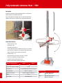
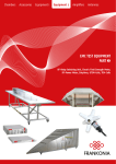
Chambers
Accessories
Equipment 1
Equipment 2
Amplifiers
Antennas
ACCESSORIES FOR
ANECHOIC CHAMBERS, OATS
AND SHIELDED ROOMS
Antenna masts, Turntables, Testing tables, Controller,
Shielded audio system, Shielded optical converter,
Shielded camera system
Content / Index
PAGE // 2
Accessories for Anechoic Chambers
Manual Antenna Masts................................................................... 3
FSM 1.6 / 2.0 / 4.0
Fully Automatic Antenna Masts......................................................... 4
FAM 4 / FAM 6
Electrical Polarization Switch............................................................ 5
FSM-EP 1
Turntables................................................................................... 5-6
FTM-Series
Freestanding Turntable................................................................... 7
FTF-0.6-0.3
Controller.................................................................................... 8-9
FC-04, FC-05
Low Reflection Testing Tables............................................................10
Shielded Audio System.................................................................... 11
FAS
Shielded Optical Converters.............................................................. 11
FOC
Shielded Camera System for mobile and fixed installation......................... 12-13
FMC-02 / FMC-02 HD
EMC-hardened Optical Transmitters.................................................... 14-15
Manual Antenna Masts – FSM 1.6 / 2.0 / 4.0
Description FSM-1.6 / FSM-2.0
The height level of the double telescopic antenna masts FSM-1.6 and FSM-2.0 can be manually adjusted
from 0.9 / 1.2 m to 1.6 / 2.0 m (depending on the model). The height setting is made within a few seconds.
In order to avoid unwanted reflections the mast rods are made of fibre glass. A collapsible tripod provides a
secure stand and easy adaption to uneven ground. The perpendicular mast adjustment is simplified with a
spirit level mounted at the tripod. A rotatable spider fixes the tripod legs for easy movement within seconds
by one person only. Antennas can be mounted directly on the 3/8” male thread or by the use of adapters for
double stacked antennas. Automatic change of the antenna polarization is possible by means of our electrical
polarization switch, type FSM-EP1 (please find a detailed description on page 5).
Technical specifications
Height range
FSM-1.6
FSM-2.0
0.9 – 1.6 m
1.2 - 2.0 m
Antenna or adapter mount
3/8” male
Material mast
fibre glass
Recommended adapters
MAS, MAD
Weight
Dimensions for transport (L x W x H)
6 kg
7 kg
1.0 x 0.3 x 0.3 m
1.2 x 0.3 x 0.3 m
Technical specifications
Height scan
Height scanning range
Required time for complete height scan
Required time for mast assembly
Antenna mount
FSM-4.0
with manual winch
0.4 – 4.15 m
<8s
< 2 min
22 mm with index ring
Mast material
fibre glass
Tripod material
zinc-plated steel
Costed option
fibre glass
Maximum antenna weight
5 kg
Total weight
13 kg
Tripod leg circuit diameter
Dimensions for the transport (L x W x H)
2.06 m
1.17 x 0.3 x 0.3 m
Description FSM-4.0
3 // PAGE
The main applications of FSM-4.0 are emission measurements, where frequent height scans are required. Level adjustment from 0.4 m to
4.15 m can easily be done by using the manual winch. The mast can be set up and disassembled without any tools within 2 minutes. The
FSM-4.0 tripod is suitable for both stationary and mobile applications. Thanks to its small transport dimensions it can be stored without problems even in small cars. The antennas are mounted with their 22 mm tube directly to the support. The polarization is fixed with an indexing
ring for both, vertical and horizontal polarization without tools. There is no additional adapter needed to fix antennas with 22 mm tubes. Each
of the three spider legs can be adjusted individually for a coarse level adjustment on uneven or inclined mounting surfaces.
Fully Automatic Antenna Mast – FAM
Description
Frankonia’s innovative range of positioning devices is entirely compatible with the EMC chamber environment.
Using a new optical communication bus, the system provides the possibility to control up to 15 devices along a single duplex fibre optic.
FAM 4 – Antenna Mast Detail
Main characteristics:
• Vertical accuracy 5 mm
• Resolution 1 mm
• Polarization accuracy 0.2°
• 30 step adjustable vertical speed from 0.01 m/s to 0.50 m/s
• Fully automatic calculation of acceleration and deceleration
ramps according to the weight of the antenna
• Manual tilting +/- 5°
• Mast positioning from 1.00 m to 4.00 m / 6.00 m
• Low noise, completely shielded hardware
• Frankonia optical communication bus
• Remote-controlled by controller type FC-04
Technical specifications
Antenna height
Max. antenna weight (incl. adapter)
Counterbalance
Polarization time
PAGE // 4
Dimensions (L x W x H)
Weight
Power supply
FAM 4
FAM 6
1.0 m - 4.0 m
1.0 m - 6.0 m
12 kg
2 x 3 kg (depending on used antenna type)
0.01 m/s - 0.50 m/s
760 mm x 800 mm x 4,200 mm
95 kg
230V, 50/60 Hz, 4A
Available Sizes
FAM 4
Frankonia Antenna Mast
for 4.0 m height scan
FAM 6
Frankonia Antenna Mast
for 6.0 m height scan
Electrical Polarization Switch – FSM-EP1
Turntables – FTM-Series
for flush mounted installations in anechoic chambers
Main characteristics FSM-EP1
• Electrical polarization swivel adapter for remote controlled change of antenna
polarization
• Compatible with all antenna masts with 3/8” thread (i. e. our type FSM)
• Power supply is provided by new series of Frankonia turntables,
e.g. FTF-0.6-0.3 or by optional available power supply unit
Technical specifications
FSM-EP1
Antenna tube fixture
22 mm
Max. antenna weight
5 kg
Mast mount
3/8" female
Power supply
12 VDC ± 25%, 150mA provided by our new turntable series or by optional available power supply unit
5m shielded cable
Neutrik cable connector NC3FXX
Recommended accessory
FSM-1.6 or any tripod with 3/8” thread
FSM-EP1
FTM-Turntables with electrical contact to the ground plane of semi-anechoic chambers or with intermediate table
for fully-anechoic chambers
Frankonia offers a wide range of turntables which are
fully compliant with the EMC chamber environment.
The turntables are available in different sizes and
with different options.
Details:
• Fully automated speed variation
• Automatic reference research
• Offset possibility
• Frankonia high conductivity grounding-ring
• Frankonia optical communication bus
5 // PAGE
• Adjustable software limits
Turntables – FTM-Series
for flush mounted installations in anechoic chambers
Technical specifications
Diameter
1.50 m - 10.00m
Load
500 kg - 60 tons
Main characteristics
Accuracy
0.1°
Resolution
0.1°
Speed
Adjustable in 30 steps
(12°/s - 0.5°/s)"
Accessories
Protective covers for apertures. The central panel
is (min. Ø 360 mm) available for any cables and
connectors.
Turntable integrated into a raised floor
Options like fully integrated rotating connection
panels or rotating exhaust systems are available
on request.
FTM x - y x: turntable diameter in meter
y: turntable load capacity in tons
Our current product range covers: FTM 1.50 – 0.50 capacity (1.50m – 500kg) up to FTM 10 – 60 (10 m – 60 tons)
Communication interfaces
PAGE // 6
The FTM series can be controlled by several Frankonia controllers.
FC-04 / FC-05
Automatic controller with GPIB IEEE 488.2 interface
FSOFT
Software for computer control using RS 232 interface
Rotating connection panel
Turntable
Rotating exhaust system
Freestanding Turntable – FTF-0.6-0.3
General
The FTF-0.6-0.3 is a freestanding turntable for use in anechoic chambers. Although the FTF-0.6-0.3 is the smallest model of Frankonia’s
turntable product range, it has numerous remarkable high end features. Due to the use of a multi turn absolute encoder the position of the
turntable is always known – this is the end of any initialization run. The optical output is the simplest solution to add a further device, e.g. an
antenna mast. The electric polarization unit FSM-EP1 is available as an accessory for the manual antenna masts FSM. Just connect the FSM-EP1
to the FTF-0.6-0.3. The supply is already integrated.
Technical specifications
0.6 m or 0.8 m
Main characteristics
Weight capacity
300 kg
• Stepper motor with integrated closed loop
Height
160 mm incl. (adjustable stand)
152 mm (without stand)
RPM
1/15 to 2 (30 steps)
Angle of rotation
± 360°
Positioning accuracy
better ± 0.5°
Interfaces
Optical input (remote), F-SMA
Optical output (additional device), F-SMA
USB (on-site), USB-B
3-pole socket (supply of electric polarization unit
FSM-EP1)
Power supply
100 - 240 VAC; 50 / 60 Hz
Weiht
39 kg
Accessories
Application software, USB-optical converter,
10 m optical fibre, power supply cable, USB cable
positioning control and multi turn absolute
encoder
• Optical INPUT for connection to positioning
controller or computer via fibre optic cables
• Optical OUTPUT for connection to further
device e.g. antenna mast
• USB-port (for on-site operation)
• Central aperture Ø 55 mm for EUT supply
• Shielded supply for electric polarization unit
FSM-EP1
7 // PAGE
Diameter
Controller FC-04
Description
Frankonia developed a complete range of controllers offering very simple control of our positioning devices. In its basic version our controller
FC-04 is able to control a turntable and 2 antenna masts (FAM 4 or FAM 6). The communication with the devices is made along a duplex optic
fibre (optical bus).
Main characteristics
• Able to control up to 15 devices
Technical specifications
• Resolution 0.1°
Rack
19“ 1U
• Frankonia optic bus system FSMA 660 nm
Weight
2.5 kg
• Standard programming language SCPI
Dimensions (L x W x H)
• Remote interface GPIB (IEEE 488.2) and USB interface
• Flash memory (possiblity to upgrade the firmware via
the USB interface)
Power supply
Frequency
482.6 mm x 172 mm x 44.3 mm
115 / 230 V – 50 Hz / 60Hz
50 Hz / 60 Hz
Application Software:
The application software of the FC-04 is running on
Microsoft Windows®.
The Software has two main functions:
1. Real time display of each drive
2. Ability to control all devices via the optical bus
PAGE // 8
The software uses either the USB interface or the GPIB
interface for positioning information. It can be connected
to the FC-04 controller for real time display or for controlling two antenna masts and one turntable.
Multi-Device Positioning Controller – FC-05
Main characteristics
• Multi-Device Positioning Controller for simultaneous operation of up to four different positioning units
• Compatible with all new Frankonia antenna masts, turntables and other positioning equipment
• Compatible with industry standard software
• IEEE 488 (GPIB) and USB interfaces
Technical specifications
Standard programming languages
SCPI
Remote Interface
GPIB (IEEE 488.2) and USB
Optical input/output
660 nm, FSMA connectors
Solenoid valve (optional)
5 / 3 way
operating pressure 3.0 - 8.0 bar
Power supply
100 - 240 VAC, 50 / 60 Hz
Dimensions (W x D x H)
482.6 x 172 x 44.3 mm
Weight
Accessories included
3.2 kg
power cord, application software, user manual
Application Software:
The application software of the FC-05 is running on Microsoft Windows®.
The Software has two main functions:
1. Real time display of each drive
2. Ability to control all devices via the optical bus
9 // PAGE
The software uses either the USB port or the GPIB interface for positioning information. It can be connected to the FC-05
controller for real time display or for controlling two antenna masts and one turntable.
Low Reflection Testing Tables
acc. to CISPR 22
EMC and RF measurements require that the used testing table does not affect the measurements being taken. The EMC testing tables from
Frankonia are designed in accordance with CISPR 22 requirements. Frankonia´s low dielectric constant, low reflectance tables are manufactured from a styrene polymer called Styropor ESP 37. The table surfaces are clad in PVC while the grid surface allows accurate positioning of
the EUT. In the center of the table is a hole which offers the possibility to feed through customer specific cables to the EUT. When not in use,
the hole is covered. The rectangular and round testing tables are available in a wide range of sizes as stated below. The EMC testing tables can
support a EUT load of up to 200 kg.
Technical specifications
PAGE // 10
Dimensions (L x W x H)
Rectangular
1.5 x 1.0 x 0.8 m
2.0 x 1.0 x 0.8 m
1.5 x 1.2 x 0.8 m
2.0 x 1.2 x 0.8 m
1.0 x 0.8 x 0.8 m
Round
1.2 m Ø, 0.8 m (h)
1.5 m Ø, 0.8 m (h)
Material
Styropor ESP37
Max. load
200 kg
Color
light grey (RAL 7035)
Cover material
PVC
Cover hole (center)
250 mm Ø
Shielded Audio Sytem – FAS
Shielded Optical Converters – FOC
FAS 3.0 - Shielded Audio System:
The audio system FAS 3.0 is able to work and guarantee high quality communications in any strong environment during EMI or EMS tests. The
FAS 3.0 system is made of passive components inside the chamber, so they are not affected by high field strengths and don’t generate any
emission according to CISPR22. Developed in collaboration with automotive EMC labs, this system passes successfully all the requirements.
Based on high quality components the FAS 3.0 is a full duplex system and guarantees a frequency response closed to HiFi requirements. (Very
sensible with a signal/rate > 89 dB and a distortion rate of 0.007 %).
High power speakers are installed into the chamber.
Main characteristics:
• Avoids any interference problems
• Equipped with ultra low noise preamplifier, compressor,
expander, feedback destroyer and several adjustable filters
• No batteries are necessary to operate the microphone
• Designed for continuous operation
FOC S – Shielded Box for Optical Converters
Frankonia integrates any type of optical converters according to your request.
In order to avoid the generation of any additional noise when installing such
equipment into a chamber, Frankonia delivers the part of optical converter into
a shielded and filtered universal box located under the ground plane of the
chamber.
For signals crossing the shielding where filters are not available:
• IEEE 488.2
• USB 1 or 2
• Ethernet 10-100-1000BT
• FireWire
• Keyboard, video, mouse of a computer
• HDMI
• Etc …
11 // PAGE
• DVI
Shielded Camera System - FMC-02 / FMC-02 HD
for mobile and fixed installation
Sophisticated control
The FMC offers full remote control possibilities available on the front panel
of the controller or via joystick. In order to facilitate the camera setup,
all camera commands are also available on the rear side of the camera
module. The display adjustment can be controlled on a removable mini
LCD screen powered by the camera itself.
General description
The FMC can be used for optical and acoustical monitoring of devices under
test during EMC measurements. The camera can be set via an external setup
LCD and eight buttons on the case or via remote control. With the optical transmission and the shielded case, the camera is well equipped for
EMC tests.
Technical specifications
Camera
General data
FMC-02
FMC-02 HD
36 x optical zoom
20 x optical zoom (20 x digital)
local and remote controlled focus, brightness function, short range LED-light,
color PAL-system, NTSC available on request, etc.
Optical transmission
digital
Optical characteristics
F= 3.4 mm (WIDE) - 122.4 mm (TELE)
F= 4.7 mm (WIDE) - 94 mm (TELE)
Perspective
ca. 57.8° (WIDE end) - 1.5° (TELE end)
ca. 55.4° (WIDE end) - 2.9° (TELE end)
320 mm (WIDE end) - 1500 mm (TELE end)
10 mm (WIDE end), 800 mm (TELE end)
PAL 4:3, color
PAL 16:9, color
440 K Pixel
~2M Pixel
Operating range
Image format
Resolution
Microphone
internal, mono (optional stereo)
Power supply
external 12V (battery pack or mains adapter, shielded)
Case dimension
130 mm x 70 mm x 80 mm incl. connectors and switches (L x W x H),
shielded aluminium case
Weight
Mounting
Miscellaneous
1/4 " tripod socket at case bottom, other threads available
remote control of all camera functions and pan-/ tilt unit, set-up display for easy adjustment of
camera stereo line, transmission, 3.5 mm plug, illumination, different types of receivers available,
(one or more channels, VGA, OSD, switch matrix, etc.)
FSMA / simplex-multimode optical fibre 62.5 / 125 µm
PAGE // 12
Connector / Type
approx. 700 g
Battery pack, camera module and additional
removable mini LCD monitor
FMC including pan- / tilt unit
PC-Recorder / Webserver
Shielded Camera System - FMC-02 / FMC-02 HD
for mobile and fixed installation
Accessories
Standard
FBC
Table top camera controller, base unit with 1 interface, remote control of camera functions via push buttons or software
(standard) 100 - 240 V, (50/60 Hz) external power supply
X
Option
FRC3-02
19" camera controller (1 HU) for max. 3 cameras (3 interfaces); interface for joystick, interface for software control,
operated via external PC, USB / RS232
X
FRC7-02
19" camera controller (2 HU) for max. 7 cameras (7 interfaces); interface for joystick, interface for software control,
operated via external PC, USB / RS232
X
LWL-VGA
Digital optical channel with standard resolution. Up to 3 units integratable in FRC3-02, up to 7 units integratable
in FRC7-02; optical connector FSMA; output connector: CVBS + VGA; stereo audio RCA
X
FAD-02
3.5" set-up LCD display, to be used for camera set-up and installation before testing, incl. connection cable
X
FBP-02
Battery pack for external power supply
X
Power supply
NiMH-battery with 10 cells, 12 V, 4 Ah, approx. 10 h
Connector / Type
5 pole, female
Dimensions & Weight
136 mm x 86 mm x 65 mm (L x W x H), 1 kg, shielded aluminium case with rubber protectors
Included items
2 pcs. battery pack, set of cables and fibres, battery charger, manual
FPS-02
Shielded mains adapter, power supply needed mainly for permanent installation
Power supply
Input: 100 VDC - 240 VDC, 50/60 Hz, Output: 12 V, 1 A
Connector / Type
rubber connector, 5 pole, female
Dimensions & Weight
136 mm x 86 mm x 65 mm (L x W x H), ca. 800 g
Included items
cable 3 m, 5 pole (male) - 3 pole (female), rubber connector, manual
FPT-02
Pan-/ tilt unit
Power supply
via camera FMC-02 (FMC-02 HD) (4 pole, female)
Connector / Type
binder series, male 4 pole - male 4 pole
Standard range
+/- 45° / 90° vertical / horizontal, others on request - depending on place of installation, final position programmable
Dimensions & Weight
ca. 65 mm x 75 mm x 100 mm (L x W x H) + mounting angle, ca. 700 g
Included items
mounting angle, shielded connection cable with folding ferrites (length: 35 cm)
15540
Recorder / Webserver for simultaneous recording of up to 4 camera signals
_
X
X
X
subsequent post-production is not possible; image format PAL 4:3; remote control via software
Record carrier
500 GB hard disk, export of data via USB / network
Connector / Type
4 x BNC, analog, PAL, USB, network RJ45 (10 /100 MBit)
Power supply
external, Input: 230 VAC, 50/60 Hz, Output: 12 VDC/ 5 A
Dimensions & Weight
270 mm x 370 mm x 70 mm (L x W x H), ca. 1.75 kg
Included items
mains adapter, USB mouse, BNC cinch adapter (1 per camera), manual
FACR4-02
PC - Recorder / Webserver for simultaneous recording of up to 4 camera signals
X
subsequent post-production via software is possible; image format: 16:10
Record carrier
500 GB hard disk, additional audio hard disk 1000 GB, DVD-RW
Connector / Type
USB, network, DVD-RW
Power supply
Input: 100 - 230 VAC, 50/60 Hz, rubber connector
Dimensions & Weight
4 HU - suitable for 19"-rack installation, 8 kg
Included items
mouse, keyboard, rubber connector, manual
FACR8-02
PC- Recorder / Webserver for simultaneous recording of up to 4 camera signals
X
subsequent post-production via software is possible; image format: 16:10
Record carrier
500 GB hard disk, additional audio hard disk 1000 GB, DVD-RW
Connector / Type
USB, network, DVD-RW
Power supply
Input: 100 - 230 VAC, 50/60 Hz, rubber connector
Dimensions & Weight
4 HU - suitable for 19"-rack installation, 8 kg
Included items
mouse, keyboard, rubber connector, manual
FACR1-02-HD
PC- Recorder / Webserver for recording of full-HD camera signals
X
subsequent post-production via software is possible; image format: 16:10
Record carrier
500 GB hard disk, additional audio hard disk 1000 GB, DVD-RW
Connector / Type
USB, network, DVD-RW
Power supply
100 - 230 VAC, 50/60 Hz
Dimensions & Weight
4 HU - suitable for 19"-rack installation, ca. 8 kg
Included items
mouse, keyboard, rubber connector, manual
Monitor
19" colour screen with VGA input
AS-02
Wooden camera tripod, height: 75-177 cm, 1/4" thread, weight: 3 kg
Wall holder
Wall holder
Miscellaneous
Feed-through for fibre optics
X
Simplex optical fibre (62.5 / 125 µm), length 20 m, FSMA-FSMA
X
X
X
13 // PAGE
X
EMC-hardened Optical Transmitters
for application at immunity tests and emission measurement
Description
EMC-hardened optical transmitters are necessary for the data transfer within or
into RF-shielded rooms/anechoic chambers during emission measurements or
radiated immunity tests. The optical data transmission ensures safe communication between inside/outside of a shielded room without any disturbances
transferred via cables and without any influence to peripherals during radiated
immunity tests. We offer optical transmitters for nearly any application.
LWL-CANx2-HS*
Technical specifications
LWL-D8
Optical 8-channel digital transmission (optional bi-directional), adjustable threshold
LWL-dAV
Digital optical transmission of analogue A/V-signals, optional miniature camera connectable
LWL-dAV-R
Receiver for digital optical transmission of analogue A/V-signals
LWL-dAV-R-Rf
Receiver for digital optical transmission of analogue A/V-signals with TV-RF-output
LWL-dAV-T
Transmitter for digital optical transmission of analogue A/V-signals
LWL-D-HS
Optical 1 to 4 channels high speed digital signal tranmission, up to 30 MHz, 3.3V tp + 5 V adjustable
LWL-F2V-100
Exchanger frequency signal => Voltage signal; 4 frequency ranges selectable up to 100 kHz
LWL-Heat
Temperature monitoring with optical output, -50 °C to + 500 °C, (optionally -200 °C to 1200 °C)
LWL-LVDS-SM_
20-1 20-channel LVDS-switching matrix, up to 2 Gbit/s
LWL-1394
Optical fire wire transmission, up to 400 Mbit/s (optionally up to 800 Mbit/s)
LWL-232-HS
Optical RS232-transmission, up to 115 kbit/s (optionally up to 1 Mbit/s)
LWL-485
Optical RS485-transmission, up to 1 Mbit/s
LWL-CANx2-HS
Optical 2-channel CAN-HS (high speed)-transmission , up to 1 Mbit/s
LWL-CAN-HS
Optical 1-channel CAN-HS (high speed)-transmission, up to 1 Mbit/s
LWL-CAN-LS
Optical 1-channel CAN-LS (low speed)-transmission, up to 125 kbit/s
LWL-CAN-SW
Optical 1-channel CAN-SW (single wire)-transmission, up to 33 kbit/s (100 kbit/s)
LWL-CML
Optical transmission of Video-signals (chip set: MAX 9259/9260), up to 2.5 Gbit/s
LWL-Flex
Optical transmission of Flexray-signals, up to 10 Mbit/s
LWLK
Optical transmission of Kline-signals (ISO 9141), min. 30 kbit/s
LWL-LAN
Optical transmission of Ethernet-signals (10 / 100 Mbit/s)
LWL-LIN
Optical transmission of LIN-signals, up to 20 kbit/s
LWL-LVDS-1-ds
Optical transmission of single-channel LVDS-signals (chip set: DS90UR124/241), up to 1.5 Gbit/s
PAGE // 14
* x = number of channels
EMC-hardened Optical Transmitters
for application at immunity tests and emission measurement
Technical specifications
LWL-LVDS-1-ds-LIN
Combination of LWL-VDS-1-ds and LWL-LIN
LWL-LVDS-4
Optical 1 to 4-channel transmission of independent LVDS-signals, up to 1.5 Gbit/s, DC-balanced
LWL-LVDS
Optical 3+1 Clk channel transmission of LVDS-signals, DC/Non-DC-balanced, Single-channel
LWL-PSI5
Optical transmission of PSI5-signals, up to 200 kbit/s, sync-, parallel-, or serial-bus
LWL-Quad
Optical 1 to 4-channel transmission, up to 1 Mbit/s Quadrature-signals (optionally bi-directional)
LWL-SENT
Optical transmission of SENT-Signals, up to 1 MHz, integrated sensor supply 5V
LWL-SENT-2-d
Optical 2-channel transmission of SENT-signals, up to 1 MHz, sync, integrated sensor supply 5 V
LWL-SPI
Optical transmission of SPI-signals, up to 1 Mbit/s, integrated sensor supply 3,3 V / 5 V
LWL-SPI-hs
Optical transmission of SPI-signals, up to 10 Mbit/s, integrated sensor supply 3,3 V / 5 V
LWL-SSI
Optical transmission of SSI-signals, up to 1 Mbit/s
LWL-TTL
Optical 16-channel transmission of TTL-signals, (optionally bi-directional), up to 100 kHz, 3.3 V / 5 V
LWL-UART-d
Optical transmission of bi-directional UART-signals (Rx+Tx), up to 20 kbit/s
LWL-USB2.0
Optical transmission of USB2.0-signals, up to 480 Mbit/s
LWL-U1-8
Optical transmission of analogue signals, min. 8 bit resolution, up to 50 MHz
LWL-U1-12-20k
Optical transmission of 1-channel analogue signals, without external power supply, up to 20 kHz
LWL-U1-14
Optical transmission of 1-channel analogue signals min. 10 bit resolution, up to 10 MHz
LWL-U1-14-30
Optical transmission of 1-channel analogue signals, min. 10 bit resolution, up to 30 MHz, +/- 1V input
LWL-U1-14i
Optical transmission of 1-channel analogue signals, min. 10 bit resolution, up to 10 MHz, additional
range of gain: 100 / 1000 with 100 kHz
LWL-U2-8
Optical 2-2-channel transmission for analogue signals, min. 8 bit resolution, up to 20 MHz
LWL-U2-12
Optical 2-channel transmission of analogue signals, min. 10 bit resolution, up to 10 MHz
LWL-U2-14-1M
Optical 2-channel transmission for analogue signals, min. 10 bit resolution, up to 1 MHz
LWL-U8-12
Optical 8-channel transmission of analogue signals, min. 10 bit resolution, up to 1 MHz
LWL-U16-12
Optical 1.16-channel transmission of analogue signals, min. 10 bit resolution, up to 100 kHz;
15 // PAGE
Copyright © by Frankonia EMC Test-Systems GmbH, 11-2012 / English Version 3.0
Frankonia EMC Test-Systems GmbH
Daimlerstraße 17, 91301 Forchheim
Germany
Frankonia GmbH
Industriestraße 16, 91180 Heideck
Germany
Web.www.frankoniagroup.com
[email protected]
Web.www.frankoniagroup.com
[email protected]
Tel.
Fax.
Tel.:
Fax:
+49 (0) 91 91 / 73 666 - 0
+49 (0) 91 91 / 73 666 - 20
+49 (0) 91 77 / 98 - 500
+49 (0) 91 77 / 98 - 520