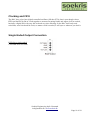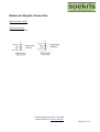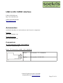
1
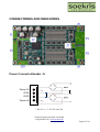
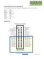
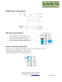
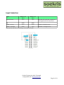
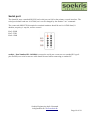
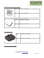
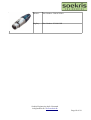
Soekris Engineering ApS dam1021 series boards. User’s Manual Vers 0.90 – September, 2015 Soekris Engineering ApS • Denmark [email protected] • www.soekris.dk Page 1 of 18 Table of Contents INTRODUCTION................................................................................................................................3 Standard Configurations.......................................................................................................................3 Specifications.......................................................................................................................................4 FEATURES..........................................................................................................................................5 CONNECTORES AND INDICATORS...............................................................................................6 Power Connector/Header J1............................................................................................................6 Power Rails Connector/Header J2...................................................................................................7 Header J3.........................................................................................................................................7 SPDIF Input Connections................................................................................................................8 I2S Input Connections.....................................................................................................................8 Volume control connection..............................................................................................................8 Input Selection.................................................................................................................................9 Serial port.......................................................................................................................................10 Clocking and FIFO........................................................................................................................11 Single Ended Output Connection...................................................................................................11 Balanced Outputs Connection.......................................................................................................12 4V RMS Zout 20 Ohm...................................................................................................................12 Power..................................................................................................................................................13 Input Voltage (J1)...............................................................................................................................13 Power Consumption.......................................................................................................................13 Filter, built in......................................................................................................................................13 Filter tool........................................................................................................................................13 UMANAGER.....................................................................................................................................14 Overview........................................................................................................................................14 uManager Commands....................................................................................................................14 Updating firmware..............................................................................................................................14 USB to I2S / SPDIF interface.............................................................................................................15 Accessories.........................................................................................................................................15 Connectors.....................................................................................................................................15 Soekris Engineering ApS • Denmark [email protected] • www.soekris.dk Page 2 of 18 INTRODUCTION The dam1021 is a DAC module based on a discrete R-2R sign magnitude DAC design, with FPGA based FIFO buffering/reclocking and custom digital filters, < 1 ps jitter clock generator, with 28 bit resolution so there is headroom, oversampling up to 3.072 Mhz. Up to 24 bit / 384 Khz input from SPDIF, I2S and USB (via USB to I2S interface board), with isolation on the I2S interface. The board is very flexible, with digital volume control and filter parameters that can be downloaded. The board is fully firmware upgradeable over a simple serial connection, which enable new features later on. The basis R-2R network has an output voltage of 1.4V RMS and output impedance of 625 ohm and can therefore drive a lot of things directly. There is also onboard balanced output drivers that can drive high impedance (>= 300 ohm) headphones directly. The power supply is also onboard, just add a 5W or larger toroid transformer. Standard Configurations - dam1021-01: - dam1021-02: - dam1021-05: 0.01% resistor version 0.02% resistor version 0.05% resistor version What is the difference between boards using 0.01%, 0.02% or 0.05% resistors ? Only the harmonic distortion get better with more precise resistors, and typically they will sound much the same as the resistors initially are better then specified. But the more precise resistors has smaller temperature drift and better long term stability, and therefore will be better in the long term. Soekris Engineering ApS • Denmark [email protected] • www.soekris.dk Page 3 of 18 Specifications dam1021 series dam1021 -01 -02 -05 THD @ -1 dB output 0.008% 0.010% 0.015% THD @ -60 dB output 0.03% 0.05% 0.09% S/N 20Khz Bandwidth 127 dB unweighted Frequency Range +0.1dB -1.0dB 20hz - 20Khz Signal Input Isolated I2S, t.ex. for external USB-I2S interface board. SPDIF digital, t.ex. for direct connection to Toslink receiver. SPDIF balanced receiver, t.ex. for AES3 of SPDIF Coax. Audio Output R-2R direct single ended: 1.4V RMS Zout 625 Ohm. Buffered single ended: 2V RMS Zout 10 Ohm. Buffered balanced: 4V RMS Zout 20 Ohm. Power input Environmental Conditions Board size 7-8V AC or +-7-15V DC max 5W Operating: 0C to 60C temperature 10% to 90% relative humidity, non condensing. Storage: -20C to 85C temperature 5% to 95% relative humidity, non condensing. 3.2" x 5.8" (81 x 147 mm) Soekris Engineering ApS • Denmark [email protected] • www.soekris.dk Page 4 of 18 FEATURES The initial rev 0.90 release of the firmware together enables the following features: 1. 2. 3. 4. 5. 6. 7. 8. I2S input up to 384KHz sample rate SPDIF input up to 192KHz Automatic De-emphasis for 44.1KHz material Built-in set of simple FIR filters for all sample rates Digital volume control through simple potentiometer Automatic input selection Data reclocking: s/w PLL with 0.02 Hz low pass filter S/W interface (serial interface) allows: 1. Volume control (e.g. with Arduino) 2. Input selection (e.g. with Arduino) 3. Loadable FIR filters including bypass filter for NOS support (s/w utility included) 4. Firmware update/upgrade Soekris Engineering ApS • Denmark [email protected] • www.soekris.dk Page 5 of 18 CONNECTORES AND INDICATORS Power Connector/Header J1 Power IN GND GND Power IN 7-8V AC or +-7-15V DC max 5W Soekris Engineering ApS • Denmark [email protected] • www.soekris.dk Page 6 of 18 Power Rails Connector/Header J2 Connector with all the power rails, for testing or for supplying (limited) power to other things.... J2 Pin 1: J2 Pin 2: J2 Pin 3: J2 Pin 4: J2 Pin 5: J2 Pin 6: J2 Pin 7: J2 Pin 8: J2 Pin 9: J2 Pin 10: GND PWR APWR A+ GND PWR -5 volt PWR +5 volt GND PWR +3.3 volt PWR +1.2 volt GND Header J3 All indputs are 3.3V level 1 2 +3.3V INP SLECT1 INP SLECT0 PWRLED VOLUME_POT GND SPDIF IN+ SPDIF1 IN- SPDIF2 IN FPGA SLV GND FPGA MCLK OUT ISO +3.3V ISO RXD IN ISO GND ISO TXD OUT ISO GND I2S BCLK IN ISO GND I2S LRCK IN ISO GND I2S DAT IN ISO GND I2S MCLK OUT ISO GND I2S FSEL IN 25 26 Isolated I2S indput Soekris Engineering ApS • Denmark [email protected] • www.soekris.dk Page 7 of 18 SPDIF Input Connections I2S Input Connections • • • • • Connect BCLK to I2S BCLK IN Pin (J3, 18) Connect LRCK to I2S LRCK IN Pin (J3, 20) Connect Data to I2S DAT IN Pin (J3, 22) Provide external 3.3V to ISO +3.3V Pin (J3, 13) AND connect I2S GND to ISO GND (J3, 15) Volume control connection Requires the use of a 10K linear potentiometer. Volume can be controlled -90 to +15 db Connect low side of potentiometer to GND Pin (J3, 11) Connect high side of potentiometer to +3.3V Pin (J3, 1) Connect Volume Pot wiper to VOLUME POT Pin (J3, 5) Soekris Engineering ApS • Denmark [email protected] • www.soekris.dk Page 8 of 18 Input Selection Input INPSLCT0 J3, 3 INPSLCT1 J3, 2 Auto Selection open open I2S GND GND SPDIF 1 (Coax) open GND Sensitive LVDS Receiver SPDIF 2 (Toslink) GND open Standard 3.3V digital level dam1021will search the 3 inputs for a valid signal and lock when found Open means that there is nothing connected to the pin Soekris Engineering ApS • Denmark [email protected] • www.soekris.dk Page 9 of 18 Serial port The dam1021 uses a standard RS-232 level serial port on J10 for the primary console interface. The serial port default baud rate is 115200, but it can be changed by the monitor “set” command. The connected ANSI/VT100 terminal or terminal emulator should be set for 115200 baud, 8 databits, no parity, 1 stop bit, no flow control. Pin 3: RXD Pin 5: TXD Pin 9: GND soekris – Part Number/SK: 14120901 converts the serial port connector to a standard PC type 9 pins D-SUB, so a serial crossover cable should be used when connecting to another PC. Soekris Engineering ApS • Denmark [email protected] • www.soekris.dk Page 10 of 18 Clocking and FIFO The DAC have a low jitter digital controlled oscillator (SiLabs si570), data is sent though a short FIFO and the FPGA and uC work together to measure incoming bitrate and adjust clock as needed, basically a digital PLL with very fast lock and very slow filtering. So the DAC itself only need serial data, word clock and bit clock, no master clock is needed, it will sync to whatever you feed it. Single Ended Output Connection R-2R direct single ended: 1.4V RMS Zout 625 Ohm. Soekris Engineering ApS • Denmark [email protected] • www.soekris.dk Page 11 of 18 Balanced Outputs Connection Buffered single ended: 2V RMS Zout 10 Ohm. Buffered balanced: 4V RMS Zout 20 Ohm. Soekris Engineering ApS • Denmark [email protected] • www.soekris.dk Page 12 of 18 Power Input Voltage (J1) Power connector, Input voltage • DC: +/- 7 to +/-15V DC; preferable 9-12V DC • AC: 2x 7-8V AC • Power goes though a diode bridge so polarity doesn’t matter. Connector is MTA156 type. Power Consumption Positive Rail: 0.18A @ 10V • Negative Rail: 0.06A @ 10V • Total: 2.4W • The positive supply draw about 3 times as much current as the negative; the current is almost independent of input voltage. Filter, built in FIR1, upsampling from incoming sample rate to 352/384 Ksps in one step, with different filter lenght based on incoming sample rate. All FIR1 filters are basic Parks-McClellan "brickwall" types, designed with http://t-filter.appspot.com/fir/index.html, but still shorter than your regular DAC. IIR, bank of 15 biquads operating at 352/384 Ksps, with one used for the CD de-emphasis filter, none otherwise used for the basic DAC. FIR2, upsampling from 352/384 Ksps to 2.8/3.1 Msps, reasonable short and soft but still using same design as FIR1. All filters are using 32 bit coefficients, with up to 67 bit MAC accumulator. Filter tool Online filter design: t-filter.appspot.com/fir/index.html Windows filter software: sourceforge.net/projects/rephase/ Soekris Engineering ApS • Denmark [email protected] • www.soekris.dk Page 13 of 18 UMANAGER Overview The dam1021 have a small 32 bit ARM based microcontroller with a monitor for configurations and control functions over the serial port, the uManager. The default serial port is set for 115200, n,8,1. The uManager monitor can be entered by entering “+++” followed by a one second pause. It will then write the signon message and a “#” prompt, then waiting for commands. The uManager is a command line driven program for configuration and downloading new firmware. Typing “?” or “Help” at the command prompt will show a short list of commands available. uManager Commands ? or Help set par=value exit update download idf df [adr] show this help set paramter to value, set alone to show exit uManager update uManager firmware download and update system flash show ID of flash dump flash content Updating firmware The dam1021 firmware can be upgraded though the serial port, either in one step or you can upgrade the uManager, FPGA or Filters seperately. When upgrading uManager you need to also enter an “update” command. 1. Download newest firmware version (unzip as needed) from www.soekris.dk 2. Connect the dam1021 serial port to a PC serial port with a terminal program, set for 115200,n,8,1, no handshake 3. Enter the uManager by typing +++. You should then get the uManager prompt 4. Type "download" and start sending file from the terminal program using 1K X-modem protocol 5. If doing a full upgrade or just uManager, type “update” 6. Power cycle when done, you can verify by entering uManager again, uManager and/or FPGA revision should then be updated to newest version Soekris Engineering ApS • Denmark [email protected] • www.soekris.dk Page 14 of 18 USB to I2S / SPDIF interface USB to I2S/DSD from http://www.diyinhk.com OEM Combo384 Module http://amanero.com/ Accessories worldwide distributor of semiconductors and electronic components Digi-Key http://www.digikey.com Mouser Electronics http://www.mouser.com Connectors J1: TE Connectivity / AMP - P/N: 640445-4 Connector is MTA156 type. House: TE Connectivity / AMP - P/N: 3-640428-4 Mouser: Part number: 571-3-640428-4 Digikey: Part number: A31242-ND Soekris Engineering ApS • Denmark [email protected] • www.soekris.dk Page 15 of 18 J2: Molex Connector Corporation / 10 pin Mouser: Part Number: 538-90120-0770 Digikey: Part Number: WM8092-ND House: Molex Wire Housings series 90123 Mouser: Part Number: 538-90156-0150 Digikey: Part Number: WM8025-ND Mouser: Part Number: 571-1023876 Digikey: Part Number: A25906-ND J3: Connector 2x13 pin Soekris Engineering ApS • Denmark [email protected] • www.soekris.dk Page 16 of 18 J6, J7, J8: TE Connectivity Series: MTA-100 Mouser: Part Number: 571-6404544 Digikey: Part Number: A19431-ND House: TE Connectivity Series: MTA-100 Headers & Wire Housings Mouser: Part Number: 571-13758204 Digikey: Part Number: A111859-ND J10: Connector 2x5 pin Mouser: Part Number: 571-1023871 Digikey: Part Number: A25901-ND P1, P2: Neutrik – P/N: NC3MAAH Soekris Engineering ApS • Denmark [email protected] • www.soekris.dk Page 17 of 18 Mouser: Part Number: 568-NC3FXX Digikey: Part Number: SC1001-ND Soekris Engineering ApS • Denmark [email protected] • www.soekris.dk Page 18 of 18