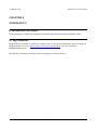
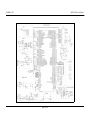
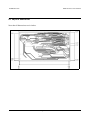
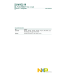
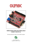
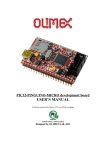
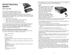
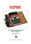
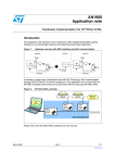
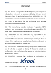
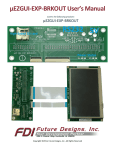
1
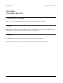
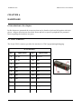
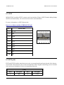
MOD-LCD4.3 development board
USER’S MANUAL
Initial release, March 2012
Designed by OLIMEX Ltd, 2011
All boards produced by Olimex LTD are ROHS compliant
OLIMEX© 2012
MOD-LCD4.3 User's Manual
Disclaimer:
© 2012 Olimex Ltd. Olimex®, logo and combinations thereof, are registered trademarks of Olimex Ltd.
Other terms and product names may be trademarks of others.
The information in this document is provided in connection with Olimex products. No license, express
or implied or otherwise, to any intellectual property right is granted by this document or in connection
with the sale of Olimex products.
Neither the whole nor any part of the information contained in or the product described in this document may
be adapted or reproduced in any material from except with the prior written permission of the copyright
holder.
The product described in this document is subject to continuous development and improvements. All
particulars of the product and its use contained in this document are given by OLIMEX in good faith.
However all warranties implied or expressed including but not limited to implied warranties of
merchantability or fitness for purpose are excluded. This document is intended only to assist the reader in the
use of the product. OLIMEX Ltd. shall not be liable for any loss or damage arising from the use of any
information in this document or any error or omission in such information or any incorrect use of the
product.
Thank you for purchasing MOD-LCD4.3 development board assembled by
OLIMEX LTD
Page 2 of 26
OLIMEX© 2012
MOD-LCD4.3 User's Manual
Table of Contents
CHAPTER 1.................................................................................................................5
OVERVIEW.................................................................................................................5
1. Introduction to the chapter.......................................................................................................5
1.1 Features.....................................................................................................................................5
1.2 Organization.............................................................................................................................6
CHAPTER 2 ................................................................................................................7
SETTING UP THE MOD-LCD4.3 BOARD.............................................................7
2. Introduction to the chapter.......................................................................................................7
2.1 Electrostatic warning...............................................................................................................7
2.2 Requirements...........................................................................................................................7
2.3 Powering the board..................................................................................................................8
2.4 Prebuilt software......................................................................................................................8
CHAPTER 3.................................................................................................................9
MOD-LCD4.3 BOARD DESCRIPTION..................................................................9
3. Introduction to the chapter.......................................................................................................9
3.1 Layout (top view).....................................................................................................................9
3.2 Layout (bottom view)...............................................................................................................9
CHAPTER 4...............................................................................................................10
THE LPC2478FBD208 MICROCONTROLLER..................................................10
4. Introduction to the chapter.....................................................................................................10
4.1 The microcontroller...............................................................................................................10
CONTROL CIRCUITY............................................................................................13
5. Introduction to the chapter.....................................................................................................13
5.1 Reset........................................................................................................................................13
5.2 Clock.......................................................................................................................................13
CHAPTER 6...............................................................................................................14
HARDWARE.............................................................................................................14
6. Introduction to the chapter.....................................................................................................14
6.1 JTAG connector.....................................................................................................................14
6.2 UEXT......................................................................................................................................15
6.3 EXT1 pads..............................................................................................................................15
6.4 EXT2 pads..............................................................................................................................16
6.5 mini USB (device)...................................................................................................................17
6.6 PWR Jack...............................................................................................................................18
6.7 micro SD/MMC slot...............................................................................................................18
Page 3 of 26
OLIMEX© 2012
MOD-LCD4.3 User's Manual
6.8 Jumper description................................................................................................................19
6.9 Touchscreen display with backlight.....................................................................................20
6.10 Additional hardware components......................................................................................20
CHAPTER 7...............................................................................................................21
MEMORY..................................................................................................................21
7. Introduction to the chapter.....................................................................................................21
7.1 Block diagram........................................................................................................................21
7.2 Memory map..........................................................................................................................22
CHAPTER 8...............................................................................................................23
SCHEMATICS...........................................................................................................23
8. Introduction to the chapter.....................................................................................................23
8.1 Eagle schematic......................................................................................................................23
8.2 Physical dimensions...............................................................................................................25
CHAPTER 9...............................................................................................................26
REVISION HISTORY..............................................................................................26
9. Introduction to the chapter.....................................................................................................26
9.1 Document revision.................................................................................................................26
9.2 Web page of your device.......................................................................................................26
Page 4 of 26
OLIMEX© 2012
MOD-LCD4.3 User's Manual
CHAPTER 1
OVERVIEW
1. Introduction to the chapter
Thank you for choosing the MOD-LCD4.3 development board from Olimex! This document
provides a User’s Guide for the Olimex MOD-LCD4.3 development board. As an overview, this
chapter gives the scope of this document and lists the board’s features. The document’s
organization is then detailed.
The MOD-LCD4.3 development board enables code development of applications running on the
LPC2478 microcontroller, manufactured by NXP.
The board is suitable as a touchscreen LCD extension to existing and future Olimex boards that
have UEXT connector. Also due to the flexible flat cable connecting the display to the board, it is
very easy for the LCD to be embedded in industrial panels.
1.1 Features
•
•
MCU: LPC2478 512KB Flash, 98KB RAM, 72Mhz
LCD 4.3" 480x272 pixels 24bit color TFT color with Backlight and Touchscreen
•
•
micro SD card
32MB of SDRAM
•
•
DC-DC for the LCD backlight
UEXT connector to interface with any of our development boards with UEXT connector
•
•
mini USB device connector
optional 3-axis digital accelerometer with 11 bit accuracy
•
•
USB device connector
JTAG connector
•
•
RESET button and circuit
USER button
•
•
power supply LED
USB activity LED
•
•
Touchscreen interface
EXT1 and EXT2 2x20 pin 0.05" extension connectors on the board edge for all unused
Page 5 of 26
OLIMEX© 2012
MOD-LCD4.3 User's Manual
LPC2478 ports
•
•
FR-4, 1.5 mm, red soldermask, component print
Dimensions: 115mm x 67.5mm (4.5'' x 2.7'')
1.2 Organization
Each section in this document covers a separate topic, organized as follow:
–
–
Chapter 1 is an overview of the board usage and features
Chapter 2 provides a guide for quickly setting up the board
–
–
Chapter 3 contains the general board diagram and layout
Chapter 4 describes the component that is the heart of the board: the LPC2478FBD208
microcontroller
–
–
Chapter 5 is an explanation of the control circuitry associated with the microcontroller to
reset. Also shows the clocks on the board
Chapter 6 covers the connector pinout, peripherals and jumper description
–
–
Chapter 7 shows the memory map
Chapter 8 provides the schematics
–
Chapter 9 contains the revision history
Page 6 of 26
OLIMEX© 2012
MOD-LCD4.3 User's Manual
CHAPTER 2
SETTING UP THE MOD-LCD4.3 BOARD
2. Introduction to the chapter
This section helps you set up the MOD-LCD4.3 development board for the first time.
Please consider first the electrostatic warning to avoid damaging the board, then discover the
hardware and software required to operate the board.
The procedure to power up the board is given, and a description of the default board behavior is
detailed.
2.1 Electrostatic warning
MOD-LCD4.3 is shipped in a protective anti-static package. The board must not be exposed to high
electrostatic potentials. A grounding strap or similar protective device should be worn when
handling the board. Avoid touching the component pins or any other metallic element.
2.2 Requirements
In order to set up the MOD-LCD4.3, the following items are required:
–
–
A source of power applied to at least one of the following:
– mini USB – standard 5V
–
–
PWR JACK - 9-12Vdc or 6-9Vac
JTAG – 5V from the JTAG debugger
–
–
UEXT – 3.3V from external host device connected to the UEXT
EXT1/EXT2 – 5V applied directly
A programmer that has 20 pin interface and supports programming of LPC2478
You may use any of Olimex’s ARM-JTAG programmer/debugger (For example ARM-USB-TINYH) for this task.
Also, a host-based software toolchain is required in order to program/debug the MOD-LCD4.3
board. There are also a number of ready IDEs available like IAR Embedded Workbench, Rowley
CrossWorks, etc.
Olimex also maintains own distribution of GCC and Eclipse suitable for use with our programmers.
Page 7 of 26
OLIMEX© 2012
MOD-LCD4.3 User's Manual
2.3 Powering the board
On powering the board the PWR LED, the SD LED and the display should turn on. After that the
touchscreen should show a simple color palette and a mouse pointer that responses on dragging.
If measuring the current consumption it should be around 15 mA.
2.4 Prebuilt software
On arrival the board has a basic demo installed which features test of the LEDs, the color range and
the touch response of the LCD, the SD card slot and the USB connectivity.
Page 8 of 26
OLIMEX© 2012
MOD-LCD4.3 User's Manual
CHAPTER 3
MOD-LCD4.3 BOARD DESCRIPTION
3. Introduction to the chapter
Here you get acquainted with the main parts of the board. Note the names used on the board differ
from the names used to describe them. For the actual names check the MOD-LCD4.3 board itself.
3.1 Layout (top view)
3.2 Layout (bottom view)
Page 9 of 26
OLIMEX© 2012
MOD-LCD4.3 User's Manual
CHAPTER 4
THE LPC2478FBD208 MICROCONTROLLER
4. Introduction to the chapter
In this chapter is located the information about the heart of MOD-LCD4.3 – its microcontroller. The
information is a modified version of the datasheet provided by its manufacturers.
4.1 The microcontroller
•
•
ARM7TDMI-S processor, running at up to 72 MHz.
512 kB on-chip flash program memory with In-System Programming (ISP) and InApplication Programming (IAP) capabilities. Flash program memory is on the ARM local
bus for high performance CPU access.
•
98 kB on-chip SRAM includes:
- 64 kB of SRAM on the ARM local bus for high performance CPU access.
- 16 kB SRAM for Ethernet interface. Can also be used as general purpose SRAM.
- 16 kB SRAM for general purpose DMA use also accessible by the USB.
- 2 kB SRAM data storage powered from the RTC power domain.
LCD controller, supporting both Super-Twisted Nematic (STN) and Thin-Film Transistors
(TFT) displays.
- Dedicated DMA controller.
- Selectable display resolution (up to 1024 × 768 pixels).
- Supports up to 24-bit true-color mode.
•
•
•
Dual Advanced High-performance Bus (AHB) system allows simultaneous Ethernet DMA,
USB DMA, and program execution from on-chip flash with no contention.
EMC provides support for asynchronous static memory devices such as RAM, ROM and
flash, as well as dynamic memories such as Single Data Rate SDRAM.
•
•
Advanced Vectored Interrupt Controller (VIC), supporting up to 32 vectored interrupts.
General Purpose AHB DMA controller (GPDMA) that can be used with and SD/MMC
interface as well as for memory-to-memory transfers.
•
Serial Interfaces:
- Ethernet MAC with MII/RMII interface and associated DMA controller. These
functions reside on an independent AHB.
- USB 2.0 full-speed dual-port device/host/OTG controller with on-chip PHY and
associated DMA controller.
Page 10 of 26
OLIMEX© 2012
-
•
•
•
•
•
•
MOD-LCD4.3 User's Manual
Four UARTs with fractional baud rate generation, one with modem control I/O, one
with IrDA support, all with FIFO.
CAN controller with two channels.
SPI controller.
Two SSP controllers, with FIFO and multi-protocol capabilities. One is an alternate for
the SPI port, sharing its interrupt. SSPs can be used with the GPDMA controller.
Three I2C-bus interfaces (one with open-drain and two with standard port pins).
I2S (Inter-IC Sound) interface for digital audio input or output. It can be used with the
GPDMA.
Other peripherals:
- SD/MMC memory card interface.
- 160 General purpose I/O pins with configurable pull-up/down resistors.
- 10-bit ADC with input multiplexing among 8 pins.
- 10-bit DAC.
- Four general purpose timers/counters with 8 capture inputs and 10 compare outputs.
Each timer block has an external count input.
- Two PWM/timer blocks with support for three-phase motor control. Each PWM has an
external count inputs.
- Real-Time Clock (RTC) with separate power domain. Clock source can be the RTC
oscillator or the APB clock.
- 2 kB SRAM powered from the RTC power pin, allowing data to be stored when the
rest of the chip is powered off.
- WatchDog Timer (WDT). The WDT can be clocked from the internal RC oscillator,
the RTC oscillator, or the APB clock.
Single 3.3 V power supply (3.0 V to 3.6 V).
4 MHz internal RC oscillator trimmed to 1 % accuracy that can optionally be used as the
system clock.
Three reduced power modes: idle, sleep, and power-down.
Four external interrupt inputs configurable as edge/level sensitive. All pins on port 0 and
port 2 can be used as edge sensitive interrupt sources.
Processor wake-up from Power-down mode via any interrupt able to operate during Powerdown mode (includes external interrupts, RTC interrupt, USB activity, Ethernet wake-up
interrupt, CAN bus activity, port 0/2 pin interrupt).
•
•
Two independent power needed features.
Each peripheral has its own clock divider for further power saving. These dividers help
reduce active power by 20 % to 30 %.
•
•
Brownout detect with separate thresholds for interrupt and forced reset.
On-chip power-on reset.
•
•
On-chip crystal oscillator with an operating range of 1 MHz to 24 MHz.
On-chip PLL allows CPU operation up to the maximum CPU rate without the need for a
Page 11 of 26
OLIMEX© 2012
MOD-LCD4.3 User's Manual
high frequency crystal. May be run from the main oscillator, the internal RC oscillator, or
the RTC oscillator.
•
•
Boundary scan for simplified board testing.
Versatile pin function selections allow more possibilities for using on-chip peripheral
functions.
•
•
Standard ARM test/debug interface for compatibility with existing tools.
Emulation trace module supports real-time trace.
For comprehensive information on the microcontroller visit the NXP’s web page for a datasheet.
At the moment of writing the microcontroller datasheet can be found at the following link:
http://www.nxp.com/documents/data_sheet/LPC2478.pdf
Page 12 of 26
OLIMEX© 2012
MOD-LCD4.3 User's Manual
CHAPTER 5
CONTROL CIRCUITY
5. Introduction to the chapter
Here you can find information about reset circuit and quartz crystal locations.
5.1 Reset
MOD-LCD4.3 reset circuit includes R25 (33 KΩ), C8 (100 nF), LPC2478 pin 35 (NRST) and a
RESET button. The RESET is also connected to the JTAG pin 15.
5.2 Clock
12 MHz quartz crystal Q1 is connected to pins 44 and 46 of the processor.
Real time clock (RTC) Q2 @ 32 768 Hz is found at pins 34 and 36 of the processor.
Page 13 of 26
OLIMEX© 2012
MOD-LCD4.3 User's Manual
CHAPTER 6
HARDWARE
6. Introduction to the chapter
In this chapter are presented the connectors that can be found on the board all together with their
pinout. Jumpers functions are described. Notes and info on specific peripherals are presented.
Notes regarding the interfaces are given.
6.1 JTAG connector
The 20 pin JTAG connector provides the interface for JTAG programming/debugging.
JTAG interface
Pin #
Signal Name
Pin #
Signal Name
1
+3.3V
11
+3.3 V
2
+3.3V
12
GND
3
TRST
13
TDO
4
GND
14
GND
5
TDI
15
RST
6
GND
16
GND
7
TMS
17
GND
8
GND
18
GND
9
TCK
19
+5V_JTAG
10
GND
20
GND
Page 14 of 26
OLIMEX© 2012
MOD-LCD4.3 User's Manual
6.2 UEXT
MOD-LCD4.3 board has UEXT connector and can interface Olimex's UEXT boards adding display
and SD card functionality. Of course the board can be used standalone.
For more information on UEXT please visit:
http://www.olimex.com/dev/OTHER/UEXT.pdf
Pin #
Signal Name
1
+3.3V
2
GND
3
TXD0
4
RXD0
5
SCL2
6
SDA2
7
MISO
8
MOSI
9
SCK
10
SSL
6.3 EXT1 pads
EXT1 and EXT2 lead the unused processor pins to neat pads positioned near the end of the bottom
of the board. Note that there isn't connectors attached to them. Signals named Px[y] can be checked
in the processor's datasheet for their corresponding functions.
EXT1
Pin #
Pin signal
Pin #
Pin signal
1
GND
2
3.3V
Page 15 of 26
OLIMEX© 2012
MOD-LCD4.3 User's Manual
3
+5V
4
Vin
5
GND
6
P2[3]
7
P2[5]
8
P2[11]
9
P2[14]
10
P2[15]
Pin #
Signal name
Pin #
Singal name
11
P2[19]
12
P2[21]
13
P2[22]
14
P2[23]
15
P2[25]
16
P2[26]
17
P2[27]
18
P2[30]
19
P2[31]
20
P3[16]
21
P3[17]
22
P3[18]
23
P3[19]
24
P3[20]
25
P3[21]
26
P3[22]
27
P3[23]
28
P3[24]
29
P3[25]
30
P3[26]
31
P3[27]
32
P3[28]
33
P3[29]
34
P3[30]
35
P3[31]
36
P4[15]
37
P4[16]
38
P4[17]
39
P4[18]
40
P4[19]
6.4 EXT2 pads
EXT2
Pin #
Pin signal
Pin #
Pin signal
1
GND
2
3.3V
3
+5V
4
Vin
5
GND
6
P4[22]
7
P4[23]
8
P4[24]
9
P4[26]
10
P4[27]
11
P4[30]
12
P4[31]
13
ALARM
14
P1[31]
Page 16 of 26
OLIMEX© 2012
MOD-LCD4.3 User's Manual
15
P1[30]
16
P1[17]
17
P1[16]
18
P1[15]
19
P1[14]
20
P1[13]
Pin #
Signal name
Pin #
Singal name
21
P1[10]
22
P1[9]
23
P1[8]
24
P1[4]
25
P1[1]
26
P1[0]
27
USB_D-2
28
P0[31]
29
P0[28]
30
P0[27]
31
P0[26]
32
P0[25]
33
P0[20]
34
P0[19]
35
P0[13]
36
P0[12]
37
P0[11]
38
P0[10]
39
P0[1]
40
P0[0]
6.5 mini USB (device)
Pin #
Signal Name
1
+5V
2
D-
3
D+
4
Not connected
5
GND
Page 17 of 26
OLIMEX© 2012
MOD-LCD4.3 User's Manual
6.6 PWR Jack
Pin #
Signal Name
1
Power Input
2
GND
6.7 micro SD/MMC slot
Note that the micro SD cards supported are up to 2GB of size.
Pin #
Signal Name
1
MCIDAT2
2
MCIDAT3
3
MCICMD
4
VDD
5
MCICLK
6
VSS
7
MCIDAT0
8
MCIDAT1
Page 18 of 26
OLIMEX© 2012
MOD-LCD4.3 User's Manual
6.8 Jumper description
Most of the jumper configurations are printed with white print on the PCB for your convenience.
This board has only SMT jumpers which require soldering/unsoldering.
VDDA_E
When closed supplies power to the external memory.
Default state is closed.
3.3V_UEXT_E
When open enables UEXT connector.
Default state is open.
3.3V_E
When open disables the power supply to the processor.
Default state is closed.
VREF_E
When open disconnects VREF on the processor (PIN24)
Default state is closed.
Page 19 of 26
OLIMEX© 2012
MOD-LCD4.3 User's Manual
6.9 Touchscreen display with backlight
Anti-glare surface treatment
Pixels: 480 × 3(RGB) × 272 Pixels,
Dot pitch: 0.066(W) × 0.198(H) mm
More info: http://www.datamate-j.com/201202/GFT043HA480272Y_Rev.A.pdf
6.10 Additional hardware components
The components below are mounted on MOD-LCD4.3 but are not discussed above. They are listed
here for completeness:
Accelerometer
Additional SDRAM
Buttons BUT + RST
2 status LEDs + PWR LED
Page 20 of 26
OLIMEX© 2012
MOD-LCD4.3 User's Manual
CHAPTER 7
MEMORY
7. Introduction to the chapter
On the next page you can find a memory map for this family of processors. It is strongly
recommended to refer to the original datasheet released by NXP for one of higher quality.
7.1 Block diagram
As shown in the processor's documentation
Page 21 of 26
OLIMEX© 2012
MOD-LCD4.3 User's Manual
7.2 Memory map
Page 22 of 26
OLIMEX© 2012
MOD-LCD4.3 User's Manual
CHAPTER 8
SCHEMATICS
8. Introduction to the chapter
In this chapter are located the schematics describing logically and physically MOD-LCD4.3.
8.1 Eagle schematic
MOD-LCD4.3 schematic is visible for reference here. You can also find them on the web page for
MOD-LCD4.3 at our site: http://olimex.com/dev/mod-lcd43.html. They are located in
HARDWARE section.
The EAGLE schematic is situated on the next page for quicker reference.
Page 23 of 26
OLIMEX© 2012
MOD-LCD4.3 User's Manual
Page 24 of 26
OLIMEX© 2012
MOD-LCD4.3 User's Manual
8.2 Physical dimensions
Note that all dimensions are in inches.
Page 25 of 26
OLIMEX© 2012
MOD-LCD4.3 User's Manual
CHAPTER 9
REVISION HISTORY
9. Introduction to the chapter
In this chapter you will find the current and the previous version of the document you are reading.
Also the web-page for your device is listed. Be sure to check it after a purchase for the latest
available updates and examples.
9.1 Document revision
Revision
Changes
Modified
Pages
A
Initial Creation
All
9.2 Web page of your device
The web page you can visit for more info on your device is http://olimex.com/dev/mod-lcd43.html.
There you can find more info and some examples.
ORDER CODES:
MOD-LCD4.3 - completely assembled and tested
ARM-USB-TINY - for custom programming/debugging
ARM-USB-TINY-H - for custom programming/debugging
USB-MINI-CABLE - USBmini to USB-A cable
How to order?
You can order to us directly or by any of our distributors.
Check our webpage http://www.olimex.com/ for more info.
Page 26 of 26