1
6000i CNC User’s Manual
November 2009
www.anilam.com
CNC User’s Manual
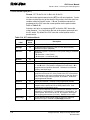
P/N 627 785-22 - Contents
Section 1 - Introduction
Effectivity Notation ........................................................................................................................... 1-1
Getting Started ................................................................................................................................. 1-2
Programming Concepts.................................................................................................................... 1-3
Programs.......................................................................................................................................... 1-3
Axis Descriptions .............................................................................................................................. 1-3
X-Axis ........................................................................................................................................... 1-4
Y-Axis ........................................................................................................................................... 1-4
Z-Axis ........................................................................................................................................... 1-4
Defining Positions ............................................................................................................................ 1-5
Polar Coordinates ......................................................................................................................... 1-6
Absolute Positioning ..................................................................................................................... 1-6
Incremental Positioning ................................................................................................................ 1-7
Angle Measurement ......................................................................................................................... 1-7
Plane Selection ................................................................................................................................ 1-8
Arc Direction..................................................................................................................................... 1-9
Section 2 - CNC Console and Software Basics
The Console ..................................................................................................................................... 2-1
Keypad ............................................................................................................................................. 2-2
Alphanumeric Keys....................................................................................................................... 2-3
Editing Keys ................................................................................................................................. 2-6
CNC Keyboard (Option) ................................................................................................................... 2-6
Soft Keys (F1) to (F10) ..................................................................................................................... 2-6
Manual Panel ................................................................................................................................... 2-6
Software Basics ............................................................................................................................... 2-7
Pop-Up Menus.............................................................................................................................. 2-7
Clearing Entries ............................................................................................................................ 2-8
Operator Prompts ......................................................................................................................... 2-8
Cursor ........................................................................................................................................... 2-8
Overwrite and Inserting Text......................................................................................................... 2-8
Deleting Text ................................................................................................................................ 2-8
Section 3 - Manual Operation and Machine Setup
Powering On the CNC ...................................................................................................................... 3-1
Shutting Down the CNC ................................................................................................................... 3-5
Emergency Stop (E-STOP) ................................................................................................................ 3-5
Activating/Resetting the Servos ....................................................................................................... 3-5
Manual Panel ................................................................................................................................... 3-6
Manual Panel Keys....................................................................................................................... 3-7
Manual Panel LEDs ...................................................................................................................... 3-8
Manual Mode Screen ....................................................................................................................... 3-9
Machine Status Display Area Labels .......................................................................................... 3-10
Program Area Labels .................................................................................................................. 3-10
Manual Mode Settings ................................................................................................................... 3-11
PLC, OLM, OSC, and SIK Descriptions...................................................................................... 3-13
Shut Down (SHIFT + F10) ............................................................................................................ 3-13
Messages (Msgs) (SHIFT + F1) ................................................................................................... 3-14
Activating Manual Mode Rapid or Feed ...................................................................................... 3-15
Adjusting Rapid Move Speed ..................................................................................................... 3-15
Adjusting Feedrate ..................................................................................................................... 3-15
Absolute Mode............................................................................................................................ 3-16
All rights reserved. Subject to change without notice.
November 2009
iii
CNC User’s Manual
P/N 627 785-22 - Contents
Jog Moves ...................................................................................................................................... 3-17
Changing the Jog Mode ............................................................................................................. 3-17
Selecting an Axis ........................................................................................................................ 3-17
Jogging the Machine (Incremental Moves) ................................................................................. 3-18
Jogging the Machine (Continuous Moves) ................................................................................. 3-18
Manual Data Input Mode ................................................................................................................ 3-19
Using Manual Data Input Mode .................................................................................................. 3-20
Operating the Handwheel (Optional) .............................................................................................. 3-21
Section 4 - Preparatory Functions: G-Codes
Rapid Move – End-Point (G0) .......................................................................................................... 4-4
Feed Move – End-Point (G1) ........................................................................................................... 4-5
Angular Motion Programming Example ............................................................................................ 4-6
Circular Interpolation (G2 and G3) ................................................................................................... 4-7
Examples of Circular Interpolation ................................................................................................ 4-8
Dwell (G4) ...................................................................................................................................... 4-11
Programming Non-modal Exact Stop (G9) ..................................................................................... 4-12
Plane Selection (G17, G18, G19) ................................................................................................... 4-12
Setting Stroke Limit (G22) .............................................................................................................. 4-14
Reference Point Return (G28) ........................................................................................................ 4-15
Return from Reference Point (G29) ............................................................................................... 4-16
Move Reference from Machine Home (G30).................................................................................. 4-17
Probe Move (G31) .......................................................................................................................... 4-17
Fixture Offset (Work Coordinate System Select) (G53) ................................................................. 4-18
Fixture Offset Table .................................................................................................................... 4-18
Activating the Fixture Offset Table.............................................................................................. 4-19
Changing Fixture Offsets in the Table ........................................................................................ 4-19
Adjusting Fixture Offsets in the Table ......................................................................................... 4-19
G53 Programming Examples...................................................................................................... 4-20
Modal Corner Radius/Chamfering (G59, G60) ............................................................................... 4-21
In-Position Mode (Exact Stop Check) (G61) .................................................................................. 4-23
Contouring Mode (Cutting Mode) (G64) ......................................................................................... 4-24
User Macros (G65, G66, G67) ....................................................................................................... 4-25
Axis Rotation (G68) ........................................................................................................................ 4-28
G68 Programming Examples...................................................................................................... 4-29
Activating Inch (G70) or MM (G71) Mode....................................................................................... 4-32
Scaling (G72) ................................................................................................................................. 4-32
Activating Absolute (G90) or Incremental (G91) Mode ................................................................... 4-33
Absolute Zero Point Programming (G92) ....................................................................................... 4-33
Mirroring (G100) ............................................................................................................................. 4-34
BlockForm (G120) .......................................................................................................................... 4-35
Programmable Temporary Path Tolerance (G1000) ...................................................................... 4-36
Feedrate (FEED) ............................................................................................................................ 4-37
Section 5 - Canned Cycles and Subprograms
Canned Cycles ................................................................................................................................. 5-1
Drilling, Tapping, and Boring Canned Cycles (G81 to G89) ............................................................. 5-2
Drilling Off (G80)........................................................................................................................... 5-3
Basic Drill Cycle (G81) ................................................................................................................. 5-3
CounterBore Drill Cycle (G82) ...................................................................................................... 5-3
Peck Drill Cycle (G83) .................................................................................................................. 5-4
Tapping Cycle (G84) .................................................................................................................... 5-5
Boring Bidirectional Cycle (G85)................................................................................................... 5-6
iv
All rights reserved. Subject to change without notice.
November 2009
CNC User’s Manual
P/N 627 785-22 - Contents
Boring Unidirectional Cycle (G86) ................................................................................................ 5-6
Chip Break Cycle (G87) ................................................................................................................ 5-7
Flat Bottom Boring Cycle (G89) .................................................................................................... 5-8
Drilling Example............................................................................................................................ 5-8
Pattern Drill Cycles ..................................................................................................................... 5-10
Drill Bolt Hole Cycle (G79) .......................................................................................................... 5-10
Drill Pattern Cycle (G179) ........................................................................................................... 5-11
Pocket Cycles ................................................................................................................................ 5-13
Draft Angle Pocket Cycle (G73).................................................................................................. 5-14
Frame Pocket Cycle (G75) ......................................................................................................... 5-16
Hole Mill Cycle (G76) .................................................................................................................. 5-18
Circular Pocket Cycle (G77) ....................................................................................................... 5-20
Rectangular Pocket Cycle (G78) ................................................................................................ 5-22
Irregular Pocket Cycle (G169) .................................................................................................... 5-24
Islands (G162) ............................................................................................................................ 5-26
Irregular Pocket Examples ......................................................................................................... 5-30
Face Mill Cycle (G170) ............................................................................................................... 5-32
Circular Profile Cycle (G171) ...................................................................................................... 5-34
Rectangular Profile Cycle (G172) ............................................................................................... 5-36
Mill Cycle (G175) ........................................................................................................................ 5-38
EndMill Cycle (G176) .................................................................................................................. 5-39
Thread Mill Cycle (G181) ............................................................................................................ 5-40
Plunge Circular Pocket Cycle (G177) ......................................................................................... 5-43
Plunge Rectangular Pocket (G178) ............................................................................................ 5-44
Slot Cycle (G210) ....................................................................................................................... 5-46
Circular Slot Cycle (G211) .......................................................................................................... 5-48
Engrave Cycle (G190) .................................................................................................................... 5-50
Subprograms .................................................................................................................................. 5-52
Subprogram Addresses .............................................................................................................. 5-53
Repetition of Subprogram (Loop) ............................................................................................... 5-53
Calling a Subprogram from a Subprogram ................................................................................. 5-54
End of Subprogram (M99) with a P-Code ................................................................................... 5-57
Subprogram for Multiple Parts Programming.............................................................................. 5-57
Loop Function ............................................................................................................................. 5-58
Probing Cycles ............................................................................................................................... 5-61
Tool Probe Cycles ...................................................................................................................... 5-62
Spindle Probe Cycles ................................................................................................................. 5-77
Section 6 - Program Editor
Activating the Program Editor........................................................................................................... 6-1
Activating Edit Mode from the Manual Screen .............................................................................. 6-2
Activating Edit Mode from the Program Manager ......................................................................... 6-2
Activating Edit Mode from Draw Graphics .................................................................................... 6-2
Editing Soft Keys .............................................................................................................................. 6-3
Move (F7) Description from Edit Screen ....................................................................................... 6-5
Edit Funct (F8) Description from Edit Screen ............................................................................... 6-6
Marking Programming Blocks .......................................................................................................... 6-7
Unmarking Program Blocks.............................................................................................................. 6-7
Saving Edits ..................................................................................................................................... 6-7
Canceling Unsaved Edits ................................................................................................................. 6-7
Deleting a Character ........................................................................................................................ 6-7
Deleting a Program Block................................................................................................................. 6-8
Inserting a Program Block ................................................................................................................ 6-8
All rights reserved. Subject to change without notice.
November 2009
v
CNC User’s Manual
P/N 627 785-22 - Contents
Undeleting a Block ........................................................................................................................... 6-9
Canceling Edits to a Program Block ................................................................................................. 6-9
Restore Canceled Edits to a Program Block .................................................................................... 6-9
Inserting Text without Overwriting Previous Text ............................................................................. 6-9
Inserting Text and Overwriting Previous Text ................................................................................. 6-10
Advancing to the Beginning or End of a Block ............................................................................... 6-10
Advancing to the First or Last Block of a Program ......................................................................... 6-10
Searching the Program Listing for Specific Text ............................................................................ 6-11
Find/Replace Description from Edit Funct (F8) Pop-up Menu .................................................... 6-12
Replacing Typed Text with New Text ............................................................................................. 6-13
Going to a Block of the Program Listing ......................................................................................... 6-13
Scrolling Through the Program ...................................................................................................... 6-14
Paging Through the Program ......................................................................................................... 6-14
Inserting a Blank Line ..................................................................................................................... 6-14
Copying Program Blocks ................................................................................................................ 6-15
Pasting Blocks within a Program .................................................................................................... 6-15
Including Comments in a Program Listing ...................................................................................... 6-16
Section 7 - Edit Help
Edit Help Soft Keys .......................................................................................................................... 7-2
Using Help Graphic Screens to Enter Program Blocks .................................................................... 7-3
G-Functions...................................................................................................................................... 7-4
Basic Modal Functions ................................................................................................................. 7-5
Tool Radius Compensation .......................................................................................................... 7-5
Arcs .............................................................................................................................................. 7-6
Milling and Profiles ....................................................................................................................... 7-9
Drilling Cycles ............................................................................................................................... 7-9
Pocket Cycles ............................................................................................................................. 7-10
Rotation, Scaling, and Mirroring ................................................................................................. 7-10
Other G-Functions ...................................................................................................................... 7-11
M-Functions ................................................................................................................................... 7-12
Basic M-Functions ...................................................................................................................... 7-12
Cooling, Cleaning, and Lubrication ............................................................................................. 7-12
Spindle Functions ....................................................................................................................... 7-12
Tool Change ............................................................................................................................... 7-12
Tools .............................................................................................................................................. 7-13
G-Code Listing ............................................................................................................................... 7-13
Entry Fields .................................................................................................................................... 7-17
M-Code Listing ............................................................................................................................... 7-18
Typing in Address Words ............................................................................................................... 7-19
Typing in M-Codes ......................................................................................................................... 7-19
Examples of G-Code Help Screens ............................................................................................... 7-20
Section 8 - Viewing Programs with Draw
Starting Draw ................................................................................................................................... 8-2
Draw Screen Description.................................................................................................................. 8-3
Display Program (F8) ................................................................................................................... 8-4
View Type (F5) ............................................................................................................................. 8-5
Adjust View (F6) ........................................................................................................................... 8-7
Opts (F9) ...................................................................................................................................... 8-8
Line Number (F8) ......................................................................................................................... 8-9
Prog Contr. (F9).......................................................................................................................... 8-10
Adjust Block Form (F1) ............................................................................................................... 8-11
vi
All rights reserved. Subject to change without notice.
November 2009
CNC User’s Manual
P/N 627 785-22 - Contents
Zoom (F2) ................................................................................................................................... 8-12
Rotate (F3) ................................................................................................................................. 8-13
Pan (F4) ..................................................................................................................................... 8-14
Move Cursor (F5) ....................................................................................................................... 8-15
Exiting Draw ................................................................................................................................... 8-16
Section 9 - Tool Page and Tool Management
Activating the Tool Page .................................................................................................................. 9-2
Using the Tool Page ......................................................................................................................... 9-3
Finding Tools by Number ................................................................................................................. 9-4
Changing Tool Page Values............................................................................................................. 9-5
Clearing a Tool (Whole Row)........................................................................................................ 9-5
Clearing a Single Value ................................................................................................................ 9-5
Adjusting a Single Value ............................................................................................................... 9-5
Tool Page Soft Keys and Secondary Soft Keys ............................................................................... 9-6
Extra Tool Information .................................................................................................................. 9-8
Bin Tool Information ..................................................................................................................... 9-8
Offset Tool Information ................................................................................................................. 9-9
Find Tool Number ......................................................................................................................... 9-9
Find in Table ............................................................................................................................... 9-10
PLC and OLM Descriptions ........................................................................................................ 9-10
T-Codes and Tool Activation .......................................................................................................... 9-11
Tool Definition Blocks ................................................................................................................. 9-11
Tool-Length Offsets ........................................................................................................................ 9-12
Entering Offsets in the Tool Page ............................................................................................... 9-13
Setting Tool-Length Offsets ........................................................................................................ 9-14
Entering the Z Position Manually ................................................................................................ 9-15
Diameter Offset in Tool Page ......................................................................................................... 9-15
Tool Path Compensation (G41, G42) ......................................................................................... 9-16
Using Tool Diameter Compensation and Length Offsets with Ball-End Mills .............................. 9-21
Compensation (G40, G41, G42) .................................................................................................... 9-21
Cancel Mode in Tool Compensation (G40)................................................................................. 9-22
Startup and Movement in Z Axis................................................................................................. 9-22
Temporary Change of Tool Diameter ......................................................................................... 9-23
Motion of Tool During Tool Compensation ................................................................................. 9-24
Compensation Around Acute Angles .......................................................................................... 9-27
General Precautions ................................................................................................................... 9-28
G41 Programming Example ....................................................................................................... 9-29
G42 Programming Example ....................................................................................................... 9-30
Activating Offsets via the Program ................................................................................................. 9-32
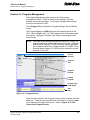
Section 10 - Program Management
Program Screen Soft Keys and Secondary Soft Keys ................................................................... 10-3
Activating the Program Screen....................................................................................................... 10-4
Changing the Program Manager Display ....................................................................................... 10-5
Creating a New Part Program ........................................................................................................ 10-7
Choosing Program Names ............................................................................................................. 10-7
Selecting a Program for Running ................................................................................................... 10-7
Selecting a Program for Editing...................................................................................................... 10-7
Deleting a Program ........................................................................................................................ 10-8
Utils Function Pop-Up Menus......................................................................................................... 10-8
Copying Programs from/to Other Directories ............................................................................... 10-10
Moving Programs from/to Other Directories ................................................................................. 10-10
All rights reserved. Subject to change without notice.
November 2009
vii
CNC User’s Manual
P/N 627 785-22 - Contents
Renaming Programs .................................................................................................................... 10-11
Marking and Unmarking Programs ............................................................................................... 10-11
Marking Programs .................................................................................................................... 10-11
Unmarking Marked Programs ................................................................................................... 10-11
Marking All Programs ............................................................................................................... 10-12
Unmarking All Marked Programs .............................................................................................. 10-12
Deleting Groups of Programs ....................................................................................................... 10-12
Creating Subdirectories ................................................................................................................ 10-12
Section 11 - Running Programs
Running a Program One Step at a Time ........................................................................................ 11-2
Using Single-Step Mode ............................................................................................................. 11-4
Holding or Canceling a Single-Step Run .................................................................................... 11-4
Single-Step Execution of Selected Program Blocks ................................................................... 11-4
Position Display Modes .................................................................................................................. 11-6
Automatic Program Execution ........................................................................................................ 11-6
Holding or Canceling an Auto Run ............................................................................................. 11-7
Starting at a Specific Block ......................................................................................................... 11-7
Clearing a Halted Program ............................................................................................................. 11-8
Using Draw While Running Programs ............................................................................................ 11-8
Parts Counter and Program Timer ............................................................................................... 11-10
Jog/Return.................................................................................................................................... 11-11
Initiating Jog/Return.................................................................................................................. 11-11
Operations Allowed While “In” Jog/Return ................................................................................ 11-11
Jog/Return Soft Keys................................................................................................................ 11-12
EXAMPLES: ............................................................................................................................. 11-13
Notes on Jog/Return................................................................................................................. 11-15
Section 12 - S and M Functions
Speed Spindle Control (S-Function) ............................................................................................... 12-1
Miscellaneous Functions (M-Code) ................................................................................................ 12-2
Control M-Codes ............................................................................................................................ 12-3
Order of Execution ......................................................................................................................... 12-4
Section 13 - Machine Software and Peripherals Installation
Keyboard Installation (Option) ........................................................................................................ 13-1
Keypad Equivalent Keyboard Keys ................................................................................................ 13-1
Peripherals Supported.................................................................................................................... 13-2
Section 14 - Off-line Software
Running and Shutting Down ........................................................................................................... 14-1
Section 15 - Four-Axis Programming
Axis Types...................................................................................................................................... 15-1
Rotary Axis Programming Conventions.......................................................................................... 15-2
Programming Examples ................................................................................................................. 15-2
Example 1: Drill ......................................................................................................................... 15-3
Example 2: Mill .......................................................................................................................... 15-4
Example 3: Mill .......................................................................................................................... 15-5
viii
All rights reserved. Subject to change without notice.
November 2009
CNC User’s Manual
P/N 627 785-22 - Contents
Section 16 - DXF Converter Feature
Requirements ................................................................................................................................. 16-1
Off-line Software ......................................................................................................................... 16-1
Machine Software ....................................................................................................................... 16-1
Entry to the DXF Converter ............................................................................................................ 16-2
Creating Shapes ......................................................................................................................... 16-3
Contours ..................................................................................................................................... 16-3
Drilling ........................................................................................................................................ 16-3
CNC Code ...................................................................................................................................... 16-4
Mouse Operations .......................................................................................................................... 16-4
DXF Soft Keys................................................................................................................................ 16-5
Fitting the Display to the Viewing Window .................................................................................. 16-6
Using the Window Zoom ............................................................................................................ 16-6
Halving Display Size ................................................................................................................... 16-6
Doubling Display Size ................................................................................................................. 16-6
DXF Entities Supported .................................................................................................................. 16-7
Drawing Entities Not Supported.................................................................................................. 16-7
Files Created .................................................................................................................................. 16-8
DXF Examples ............................................................................................................................... 16-8
Unedited Conversational Program Listing ................................................................................ 16-10
Unedited G-Code Program Listing ............................................................................................ 16-11
Unedited Program Run in Draw ................................................................................................ 16-12
Edited Conversational Program Listing .................................................................................... 16-13
Edited G-Code Program Listing ................................................................................................ 16-15
Section 17 - Advanced Programming Features
Modifiers......................................................................................................................................... 17-1
Block Separators ............................................................................................................................ 17-2
Tool Offset Modification ................................................................................................................. 17-2
Expressions and Functions ............................................................................................................ 17-5
Examples .................................................................................................................................... 17-6
System Variables ........................................................................................................................... 17-8
User Variables ................................................................................................................................ 17-9
Variable Programming (Parametric Programming) ................................................................... 17-10
User Macros (G65, G66, G67) ..................................................................................................... 17-17
Macro Body Structure ............................................................................................................... 17-18
Setting and Passing Parameters .............................................................................................. 17-18
Probe Move (G31) ........................................................................................................................ 17-26
Conditional Statements ................................................................................................................ 17-27
Unconditional LOOP Repeat ........................................................................................................ 17-29
Short Form Addressing ................................................................................................................ 17-29
Logical and Comparative Terms .................................................................................................. 17-30
Logical Terms ........................................................................................................................... 17-30
Comparative Terms .................................................................................................................. 17-30
File Inclusion ................................................................................................................................ 17-31
Index ....................................................................................................................................... Index-1
All rights reserved. Subject to change without notice.
November 2009
ix
CNC User’s Manual
P/N 627 785-22 - Introduction
Section 1 - Introduction
This manual describes the concepts, programming commands, and CNC
programming formats used to program ANILAM CNC products. Use the
Contents and Index to locate topics of interest. In general, topics are
presented in order of complexity. For example, “Section 1” describes
basic CNC topics while later sections describe Drawing Exchange Format
(DXF) converter programming and special programming features that
require a firm grasp of CNC programming.
The following topics are described in this section:
Effectivity Notation
Getting Started
Programming Concepts
Programs
Axis Descriptions
Defining Positions
Angle Measurement
Plane Selection
Arc Direction
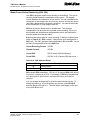
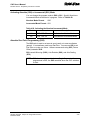
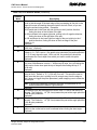
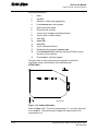
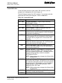
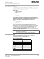
Effectivity Notation
Some sections of this manual apply only to specific ANILAM CNC
product(s). In these sections, icons in the left margin identify the
product(s) to which the information applies. Table 1-1 lists the icons for
each CNC product and the number of axes supported by each product.
Table 1-1, CNC Effectivity Icon Description
Icon
6000i-3X
6300M
6000i-4X
6400M
Product
Axes Supported
6000i-3X Systems
3
6000i-4X Systems
4
NOTE: All systems also support one spindle axis.
The main difference between the products is the number of axes
supported. Generally, this manual describes the 6000i-3X systems. The
6000i-4X operates exactly as the 6000i-3X system except for features
that include the additional axes.
All rights reserved. Subject to change without notice.
November 2009
1-1
CNC User’s Manual
P/N 627 785-22 - Introduction
Getting Started
Before you start to write a program, determine the work holding device
and the location of Part Zero (the point to which all movement is
referenced). Since absolute positions are defined from Part Zero, try to
select a location that directly corresponds to dimensions provided on the
part print, such as the lower left corner of the work. Then, you can
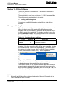
develop a program using a procedure similar to the one that follows:
1. To enter the Program Manager from the Manual screen, press
Program (F2). Create a program name for the part.
2. Enter the Program Editor (Edit F8) to open the new program and start
writing blocks.
3. The first block of any program is usually a safe start position and toolchange position (a position away from the work where the axes can
return for safe tool changing). The first block is normally also used to
specify the units of measurement (Inch/MM), mode of operation
(Absolute), move type (Rapid), and to cancel all auxiliary functions
(Tool Offsets, Spindle, and Coolant).
Typical first blocks:
G70 G90 G0 G28 Z0
M5
4. Subsequent blocks in the program set Spindle information, call Tool
number, turn on Coolant, and make the initial move toward the work.
5. The remaining blocks in the program describe the required moves,
Canned Cycles, and Tool changes to complete the machining.
6. The next to the last block in the program returns the axes to the Tool
change position, turning off any auxiliary functions (Tool Offsets,
Spindle, and Coolant). The last block (M2) ends the program.
Typical final blocks:
M9
M5
G0 G28 Z0
X0 Y0
M2
7. After you write a program, verify it. Run it in Draw Graphics Mode to
troubleshoot for errors. Verify that all programmed moves are safe
and accurate to the part print dimensions.
8. Now, load the stock material into the selected work-holding device.
9. Set the Tool Offsets for each tool in the Tool Page.
10. Before running the part in the Auto Mode, run it in Single-Step Mode
to verify that both the program and the setting of Tool Offsets have
been correctly completed. Single-Step Mode allows you to execute
the program block-by-block.
11. After you test the program, make any necessary corrections.
12. When the finished program is ready for production, back it up on a
USB Memory Stick.
1-2
All rights reserved. Subject to change without notice.
November 2009
CNC User’s Manual
P/N 627 785-22 - Introduction
Programming Concepts
This section contains programming concepts for the beginning
programmer. You must master these concepts and be familiar with the
terminology in order to write programs.
Programs
A program is the set of instructions that the CNC uses to direct the
machine movements. Each line of instructions is called a block. Each
block runs independently, thus allowing the program to be stepped along,
one block at a time.
Axis Descriptions
The machine moves along its axes of motion. All movements along an
axis are either in a positive or negative direction. Not all machines use
the same system to identify axes. The descriptions used in this manual
are commonly used to identify 3-axis mills.
NOTE: To visualize machine movements correctly, imagine tool motion
rather than table motion.
The following topics are described:
X-Axis
Y-Axis
Z-Axis
All rights reserved. Subject to change without notice.
November 2009
1-3
CNC User’s Manual
P/N 627 785-22 - Introduction
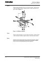
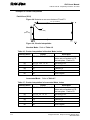
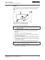
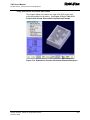
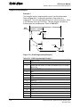
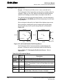
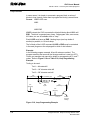
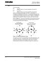
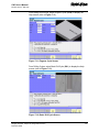
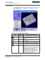
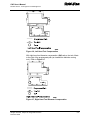
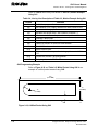
X-Axis
Table movement along the X-axis is to the left and right. Positive motion
is table movement to the left; negative motion is table movement to the
right. Refer to Figure 1-1.
Figure 1-1, Mill Axes of Motion
Y-Axis
Table movement along the Y-axis is inward and outward. Positive motion
is table movement outward; negative motion is table movement inward.
Z-Axis
Spindle movement along the Z-axis is upward and downward. Positive
motion is tool movement upward (away from the workpiece); negative
motion is tool movement downward (into the workpiece).
1-4
All rights reserved. Subject to change without notice.
November 2009
CNC User’s Manual
P/N 627 785-22 - Introduction
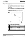
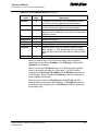
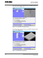
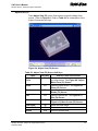
Defining Positions
The intersection of the X-, Y-, and Z-axes is the reference point from
which to define most positions. Refer to Figure 1-2. This point is the X0,
Y0, Z0 position.
Most positions are identified by there X, Y, and Z coordinates. A position
two inches left, three inches back, and four inches up has an X coordinate
of X -2.0, a Y coordinate of Y3.0, and a Z coordinate of Z4.0.
The following topics are described:
Polar Coordinates
Absolute Positioning
Incremental Positioning
Figure 1-2, Locating Positions
All rights reserved. Subject to change without notice.
November 2009
1-5
CNC User’s Manual
P/N 627 785-22 - Introduction
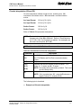
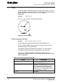
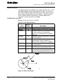
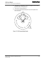
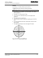
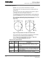
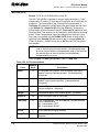
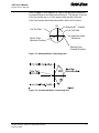
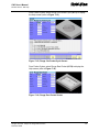
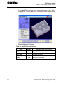
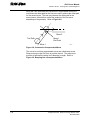
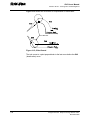
Polar Coordinates
Polar Coordinates define points that lie only on a single plane. Polar
coordinates use the distance from the origin and an angle to locate
points. Refer to Figure 1-3.
Figure 1-3, Polar Coordinate System
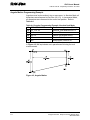
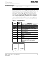
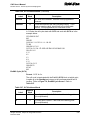
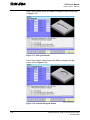
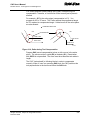
Absolute Positioning
In Absolute Mode, all positions are measured from Absolute Zero.
Absolute Zero is not a fixed position on the machine. It is a selected
point. Refer to Figure 1-4.
Figure 1-4, Absolute Positioning
You can set Absolute Zero (X0, Y0) anywhere. Usually, it is set at a
position that enables you to use the dimensions specified on the
blueprint. This is also called setting the Part Zero.
The Absolute Zero (Part Zero) can be moved as often as necessary,
either manually or in a program.
1-6
All rights reserved. Subject to change without notice.
November 2009
CNC User’s Manual
P/N 627 785-22 - Introduction
Incremental Positioning
Incremental positions are measured from one point to another, or from
the machines present position. This is convenient for performing an
operation at regular intervals. Incremental positions are measured from
the tool’s present position. Refer to Figure 1-5.
NOTE: An incremental 0 inch (0 mm) move does not make a position
change because you are located at the 0 reference point
(current position).
Figure 1-5, Incremental Positioning
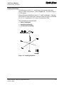
Angle Measurement
Angles are measured with the 3 o’clock position as the Zero Degree
Reference. Positive angles rotate counter-clockwise; negative angles
rotate clockwise. Refer to Figure 1-6.
Figure 1-6, Absolute Angle Measurement
All rights reserved. Subject to change without notice.
November 2009
1-7
CNC User’s Manual
P/N 627 785-22 - Introduction
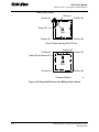
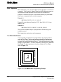
Plane Selection
Circular moves and tool diameter compensation are confined to the plane
you select. Three planes are available: the XY plane (G17), the XZ plane
(G18), and the YZ plane (G19). It is important to view a plane correctly
when you plan a circular move. If a plane is viewed from the wrong side,
arc directions, angle references, and axis signs are displayed reversed.
The standard rule is to view a plane looking in the negative direction
along the unused axis. Refer to Figure 1-7.
Figure 1-7, Plane Identification
1-8
All rights reserved. Subject to change without notice.
November 2009
CNC User’s Manual
P/N 627 785-22 - Introduction
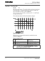
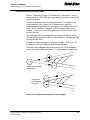
Arc Direction
The standard rule is to view arc direction for a plane from the positive
towards the negative direction along the unused axis. From this
viewpoint clockwise (Cw) and counterclockwise (Ccw) arc directions can
be determined. For example, in the XY plane, you view along the Z-axis,
from Z+ toward Z-, to determine Cw/Ccw directions. The Cw/Ccw arc
directions for each plane are shown in Figure 1-8.
Figure 1-8, Clockwise and Counterclockwise Arc Directions
All rights reserved. Subject to change without notice.
November 2009
1-9
CNC User’s Manual
P/N 627 785-22 - CNC Console and Software Basics
Section 2 - CNC Console and Software Basics
The following topics are described in this section:
The Console
Keypad
CNC Keyboard (Option)
Soft Keys (F1) to (F10)
Manual Panel
Software Basics
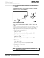
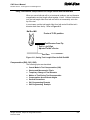
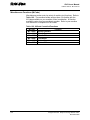
The Console
The CNC console consists of a 12.1-inch color, flat-panel liquid crystal
display (LCD), keypad, soft keys, and manual panel (MP 6000M or MP
6001M Manual Panel). Refer to Figure 2-1.
LCD
Keypad
Soft Keys
Manual
Panel
Console6000i
Figure 2-1, CNC Console
All rights reserved. Subject to change without notice.
November 2009
2-1
CNC User’s Manual
P/N 627 785-22 - CNC Console and Software Basics
Keypad
The following topics are described:
Alphanumeric Keys
Editing Keys
Refer to Figure 2-2. The keypad to the right of the LCD has the following
areas:
Alphanumeric Keys: This area consists of the letters of the alphabet
listed sequentially from A to W, and also includes
the CLEAR key (lower right), the numerical keypad
(0 through 9), and the SPACE key (lower-left).
This area contains the SHIFT (left), ENTER (right),
and the cursor control keys (ARROWS).
Edit Keys:
CLEAR
SHIFT
Key
Key Character
Alphanumeric Keys
Primary Character
SPACE
Key
Key
ARROW Keys
SHIFT Key
ENTER
Edit Keys
KEYPAD
Figure 2-2, Keypad
2-2
All rights reserved. Subject to change without notice.
November 2009
CNC User’s Manual
P/N 627 785-22 - CNC Console and Software Basics
Alphanumeric Keys
Alphanumeric keys allow you to enter position coordinates (XYZ moves)
and program G, M, S, and T codes. Some keyfaces have two characters,
a large one in the middle of the key, and a smaller one in the upper-left
corner. The large characters are Primary characters. The smaller
characters are SHIFT key characters.
To type a primary character, press the key that contains that character.
To type a SHIFT key character:
1. Press SHIFT and release. You do not need to hold down the key, the
SHIFT condition remains On until you press the next key.
2. Press the key that displays the required character in the upper-left
corner. Refer to Table 2-1.
Table 2-1, Alphanumeric Keys
Key Face
Primary Function
SHIFT Function
Letter A
None
Letter B
Less Than Symbol
Letter C
Greater Than Symbol
Letter D
Caret
Letter E
None
Letter F/Feedrate
Left Bracket
Letter G/G Codes
Right Bracket
Letter H
Exclamation Point
Letter I
None
Letter J
Apostrophe
Letter K
Tilde Symbol
Letter L
“At” Symbol
Letter M
None
Miscellaneous Functions
(Continued…)
All rights reserved. Subject to change without notice.
November 2009
2-3
CNC User’s Manual
P/N 627 785-22 - CNC Console and Software Basics
Table 2-1, Alphanumeric Keys (Continued)
Key Face
Primary Function
SHIFT Function
Letter N
Left Curly Bracket
Letter O
Right Curly Bracket
Program Number
Designator
Letter P
Dollar Sign
Letter Q
None
Letter R
Underscore
Letter S/Spindle Speed
Designator
Backslash
Letter T/Tool words
Single Quote
Letter U
None
Letter V
Question Mark
Letter W
Colon
Letter X
X Axis Coordinate
None
Letter Y
Y Axis Coordinate
None
Letter Z
Z Axis Coordinate
None
Number One
RAPID
Left Parenthesis
Number Two
LINE
Right Parenthesis
Number Three
ARC
Pound or Number Sign
Number Four
FEED
Vertical Bar: used to separate
parts of a blueprint-programming
block for angles/chamfers/radii.
Number Five
TOOL (shortcut key not
enabled)
Semi-Colon
(Continued…)
2-4
All rights reserved. Subject to change without notice.
November 2009
CNC User’s Manual
P/N 627 785-22 - CNC Console and Software Basics
Table 2-1, Alphanumeric Keys (Continued)
Key Face
Primary Function
SHIFT Function
Number Six
MCODE (shortcut key
not enabled)
Slash (Right)
Number Seven
MM/IN (shortcut key not
enabled)
Ampersand
Number Eight
DWELL (shortcut key not
enabled)
Percent Symbol
Number Nine
PLANE (shortcut key not
enabled)
Inch Symbol
Number 0
Equal Sign
Minus Sign/Dash
Plus Sign
Period/Decimal Sign
RPM (shortcut key not
enabled)
Asterisk: used to “comment out”
all or part of a block (characters
to the right of the asterisk are
ignored). The CNC ignores
these blocks.
Space Key
Blank Space
All rights reserved. Subject to change without notice.
November 2009
2-5
CNC User’s Manual
P/N 627 785-22 - CNC Console and Software Basics
Editing Keys
Use the Editing Keys to edit programs and move around the screen.
Refer to Table 2-2.
Table 2-2, Editing Keys
Label or Name
SHIFT
CLEAR
Key Face
Purpose
Displays additional options on the soft key
menu. Allows access to additional soft
keys.
Clears selected messages, values,
commands, and program blocks.
ARROW
Allows you to move highlight bars and
cursor around the screen.
ENTER
Activates menu selections, activates
alphanumeric entry, or creates new line.
Use Editing Keys to control machine movements manually. Refer to
“Section 3 - Manual Operation and Machine Setup” for a detailed
description of the Manual Panel.
CNC Keyboard (Option)
The CNC supports most standard USB PC keyboards. Refer to “Section
13 - Machine Software and Peripherals Installation.” All keypad inputs
except E-STOP and SERVO RESET have assigned keyboard equivalents.
Soft Keys (F1) to (F10)
Labeled soft keys F1 to F10, also called function keys, are located just
below the monitor. Soft key functions are not hardwired; their functions
change with changes in mode. Labels indicate the function of each soft
key. Unlabeled soft keys are inactive.
Manual Panel
Refer to “Section 3 - Manual Operation and Machine Setup” for
information on the manual panel and the optional handwheel.
2-6
All rights reserved. Subject to change without notice.
November 2009
CNC User’s Manual
P/N 627 785-22 - CNC Console and Software Basics
Software Basics
The CNC’s screens change as different modes are activated. Basic
procedures and features of the software remain the same, regardless of
the CNC’s mode.
The following topics are described:
Pop-Up Menus
Clearing Entries
Operator Prompts
Cursor
Overwrite and Inserting Text
Deleting Text
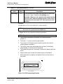
Pop-Up Menus
Pop-up menus are temporary menus that allow you to make additional
selections. Each pop-up menu contains a highlight bar. The ARROWS
move the highlight bar up and down the menu. Press ENTER to activate a
highlighted selection. Press the soft key that activated the pop-up menu
again to deactivate the function. Refer to Figure 2-3.
UTILITIES POP-UP
Figure 2-3, Pop-Up Menu
All rights reserved. Subject to change without notice.
November 2009
2-7
CNC User’s Manual
P/N 627 785-22 - CNC Console and Software Basics
Clearing Entries
Press CLEAR to clear an entry in an entry field or a character from a
program.
Operator Prompts
The CNC sometimes prompts for required information. Enter numbers
from the keypad.
Cursor
The CNC uses either a cursor or highlight to mark an item for selection or
editing. The highlight displays in the Edit Mode, Program Manager, and
Manual Mode. Use the ARROWS to move the highlight. The software
highlights a selected item in a menu or window. Selected items can be
activated or changed.
For instance, highlight a program block in Edit Mode to edit it. Highlight
an entry field label in a graphic menu to enter a value or toggle between
the available selections.
The cursor displays when the Tool Page activates. The cursor is a white
underline that indicates where letters and numbers are inserted.
Overwrite and Inserting Text
The Editor has two text-entry modes, Insert Off (overwrite) and Insert On
[Default: Insert On]. In the Insert Off (overwrite) mode, new characters
replace characters marked by the cursor.
In the Insert On mode, new characters are displayed at the cursor and
existing characters move to the right. When the Insert On mode is active,
Insert On (F8) highlights. To put the CNC in the Insert On mode:
1. When the CNC prompts for a name, toggle to Insert On (F8). The
CNC highlights Insert On (F8).
Deleting Text
To delete text:
1. Move the cursor to underline the text to be deleted.
2. Press Delete (F7) to delete the selected text.
2-8
All rights reserved. Subject to change without notice.
November 2009
CNC User’s Manual
P/N 627 785-22 - Manual Operation and Machine Setup
Section 3 - Manual Operation and Machine Setup
The following topics are described in this section:
Powering On the CNC
Shutting Down the CNC
Emergency Stop (E-STOP)
Activating/Resetting the Servos
Manual Panel
Manual Mode Screen
Manual Mode Settings
Jog Moves
Manual Date Input Mode
Operating the Handwheel (Optional)
Powering On the CNC
NOTE: When you power-on the CNC, ensure that the E-STOP switch is
in the in position.
1. Turn on the CNC according to the builder’s instructions. When the
power switch is turned on, the CNC completely resets.
2. Turn the power switch ON. The startup screen activates (see
Figure 3-1).
START
Figure 3-1, Start Screen
All rights reserved. Subject to change without notice.
November 2009
3-1
CNC User’s Manual
P/N 627 785-22 - Manual Operation and Machine Setup
3. Reset the servo drive by pressing the sERVO RESET button with the
EMERGENCY STOP button Out.
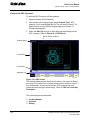
4. Press Home (F4) and then press (START) to start. The CNC displays
the Manual screen (see Figure 3-2).
MANUAL
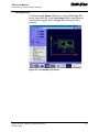
Figure 3-2, Manual Screen
5. Select Manual (F4) to display the Manual screen (refer to Figure 3-7,
Manual Screen for illustration with callouts). Refer to Table 3-3,
Manual Screen Soft Keys.
6. Press the SHIFT key on the keyboard to display the Manual Shift
screen (refer to Figure 3-3, Shift Screen from Manual Screen).
Refer to Table 3-4, Manual Screen Secondary Soft Keys.
3-2
All rights reserved. Subject to change without notice.
November 2009
CNC User’s Manual
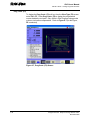
P/N 627 785-22 - Manual Operation and Machine Setup
SHIFT MANUAL
Figure 3-3, Shift Screen from Manual Screen
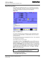
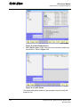
7. Press the Display Gauge (F4) soft key to display the Display Gauge
screen (refer to Figure 3-4). Select the Gauge information that you
want to display on the Manual screen:
• SpindleMotorLoad
Spindle Motor Load
• X-MotorLoad
X Axis Motor Load
• Y-MotorLoad
Y Axis Motor Load
• Z-MotorLoad
Z Axis Motor Load
DISPLAY GAUGE
Figure 3-4, Display Gauge from SHIFT Manual Screen
All rights reserved. Subject to change without notice.
November 2009
3-3
CNC User’s Manual
P/N 627 785-22 - Manual Operation and Machine Setup
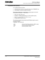
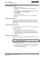
8. Press the Display Gauge (F1) soft key to display the Gauge
information on the Manual screen (refer to Figure 3-5). Refer to
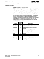
Table 3-1.
Table 3-1 describes the Display Gauge soft keys.
Table 3-1, Display Gauge Screen Soft Keys
Label
Soft Key
Function
Display
Gauge
F1
Displays the gauge information selected
on the Manual screen.
Remove
Gauge
F2
Removes the gauge information field
and label from the Manual screen.
Cancel
F10
Exits the Display Gauges screen and
does not save changes.
Display
Gauge
field
MANUALwithGAUGEInfo
Figure 3-5, Manual Screen with Gauge Display
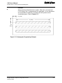
The Display Gauge field is dynamic. When the spindle motor load
increases, the field in the Display Gauge increases.
3-4
All rights reserved. Subject to change without notice.
November 2009
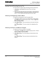
CNC User’s Manual
P/N 627 785-22 - Manual Operation and Machine Setup
Shutting Down the CNC
1. Press E-STOP to disengage the servos and then revert to Manual
Mode.
2. Press Shut Down (SHIFT+F10) to display the Shut Down soft keys.
Press Shut Down (F1) to display the power down the CNC. Press
Cancel (F2) to cancel the shut down.
3. Follow the builder’s instructions for turning off the CNC.
Emergency Stop (E-STOP)
Press E-STOP to take all axes and spindle servos offline. This ends all
machine movement.
To reset E-STOP, pull out and turn the rotary switch clockwise in the
direction of the arrows. The switch makes a clicking sound when it
resets.
Resetting E-STOP does not automatically reactivate the servos. The
servos must be reset to move the machine. Press SERVO RESET to reset
the servos.
Activating/Resetting the Servos
For safety reasons, the CNC powers up with the servomotors
disengaged. While the servos are off, the CNC cannot move the
machine. The servos are also disengaged when you press E-STOP.
Reset the servos as follows:
1. If a limit switch disengaged the servos, manually reposition the
machine inside its normal range of travel.
2. Press E-STOP to display the message External emergency stop.
3. Rotate the E-STOP switch in the direction of the arrows to reset it. The
E-STOP switch makes a clicking sound when it resets.
All rights reserved. Subject to change without notice.
November 2009
3-5
CNC User’s Manual
P/N 627 785-22 - Manual Operation and Machine Setup
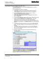
Manual Panel
Use the keys on the manual panel to move the machine manually. Refer
to Figure 3-6.
Figure 3-6, Manual Panel
The following topics are described:
3-6
Manual Panel Keys
Manual Panel LEDs
All rights reserved. Subject to change without notice.
November 2009
CNC User’s Manual
P/N 627 785-22 - Manual Operation and Machine Setup
Manual Panel Keys
Manual panel keys allow you to control machine movements manually.
These keys are located on the Manual Panel. Refer to Table 3-2.
Table 3-2, Manual Operation Keys
Label/Name
Key Face
Moves the selected controlled axis while in the Manual Mode.
Jog must be set to 1, 10, or 100. Optional.
Handwheel
Axis Select
Purpose
Y
Z
U
X
In Manual Mode, selects the axis to be jogged.
AXIS
Cycles the CNC through manual movement modes (FEED,
RAPID, 100, 10, 1). The machine builder sets Default rapid
and feed rates at setup.
JOG
NOTE: The machine builder determines the actual speed of
the machine during a move.
SPINDLE
OVERRIDE
SPINDLE
FEEDRATE
OVERRIDE
Overrides the programmed spindle RPM rate. It is a
13-position rotary switch that ranges from 40 to 160 percent.
(Each increment adjusts the spindle override by 10%.) This
feature can be used only on machines with programmable
spindles.
Overrides the feed and/or rapid rate of the axes in Manual,
Auto, and Single Step modes. It is a 13-position rotary
switch, which ranges from 0 to 120 percent. (Each increment
adjusts the feedback override by 10%.)
NOTE: The override range for rapid rate is 100%. The CNC
does not exceed the maximum rapid rate.
SERVO RESET
Activates the servomotors.
SPINDLE
FORWARD
Starts the spindle in a forward direction.
SPINDLE
REVERSE
NOTE: On some machines, you must provide the gear range
and RPM before you activate this key.
Starts the spindle in a reverse direction.
NOTE: On some machines, you must provide gear range and
RPM before you activate this key.
SPINDLE OFF
Stops the spindle.
START
Starts all machine moves except jog.
(Continued…)
All rights reserved. Subject to change without notice.
November 2009
3-7
CNC User’s Manual
P/N 627 785-22 - Manual Operation and Machine Setup
Table 3-2, Manual Operation Keys (Continued)
Label/Name
Key Face
Purpose
JOG –
Moves the selected axis in a negative direction. Available in
all modes. The machine builder specifies Feedrate.
JOG +
Moves the selected axis in the positive direction. Available in
all modes. The machine builder specifies Feedrate.
HOLD
Halts any running program or programmed move. Press
START to continue.
E-STOP
Press E-STOP to halt all axes and machine-related functions.
When you activate E-STOP, the servomotors and any
programming operations shut down. The CNC defaults to
Manual Mode.
Use E-STOP for emergency shutdown or intentional servo
shutdown.
Manual Panel LEDs
The following keys have LEDs located directly above them on the Manual
Panel. When any of the keys is activated, the corresponding LED lights
up. Refer to Figure 3-6, Manual Panel.
•
•
•
•
Servo Reset
Spindle Off
Spindle Forward
Spindle Reverse
The Coolant Ready LED is also located on the Manual Panel. Some
CNCs have a coolant ready M-function. For these CNCs, the Coolant
Ready LED lights when the coolant is ready. The coolant is programmed
to come on when the machine receives a SPINDLE ON command.
3-8
All rights reserved. Subject to change without notice.
November 2009
CNC User’s Manual
P/N 627 785-22 - Manual Operation and Machine Setup
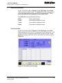
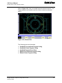
Manual Mode Screen
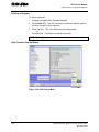
In Manual Mode, the CNC displays the Manual screen. The Manual
screen is the basic operating screen and is displayed when the CNC is
turned on. All other operating screens are similar in appearance and
selected from the Manual screen soft keys. When the Manual Mode is
active, the Manual (F4) soft key label highlights. Refer to Figure 3-7.
Program Area
Program Position
Display
Distance to Go
Area
Machine Status
Display Area
Command Line
History Area
Active Soft Key
(Highlighted)
MANUAL Screen
Figure 3-7, Manual Screen
The Manual screen is divided into the following areas.
Program Area
Displays the working program name, running
status, mode of operation, and in-position check.
Program Position Display
Displays programs X, Y, and Z position coordinates
in reference to Part Home.
Distance to Go
Displays the Distance to Go in reference to:
• Part Zero
• Target
Machine Status Display Area
Displays operating information.
Command Line
All rights reserved. Subject to change without notice.
November 2009
Allows you to enter commands manually.
3-9
CNC User’s Manual
P/N 627 785-22 - Manual Operation and Machine Setup
Active Soft Key
Identifies the function of the soft key. Soft key
functions change from screen to screen. A
highlighted label indicates an active mode.
The following topics are described:
Machine Status Display Area Labels
Program Area Labels
Machine Status Display Area Labels
Tool:
Diameter:
Length:
Offset:
G-Codes:
M-Codes:
Feed:
% Feed:
RPM:
% RPM:
Spindle:
Loop:
Parts:
Timer
Dwell:
Active tool
Active tool diameter
Z-Axis Tool-Length Offset for active tool
Active fixture offset
Active G-Codes
Active M-Codes
Current feed rate (in inch/mm per minute)
Feedrate override setting (0% to 120% for Feed moves
and 0% to 100% for Rapid moves)
Current spindle speed in revolutions per minute
Spindle override setting (40% to 160%)
Current spindle status: OFF, FORWARD, REVERSE, or
LOCKED
Loop counter. Counts subprogram repetitions.
Number of parts. Resets to zero when you enter Auto or
Single Step mode.
Indicates the amount of time per part and accumulated
amount of time (in parentheses) for all parts. Resets to
zero when you enter Auto or Single Step mode.
Seconds remaining in a dwell
Program Area Labels
Program:
Block:
IN POSN
Green Icon:
Red icon:
3-10
Name of loaded program
Block number (displays in S.Step or Auto Mode only)
All axis at target position
Program is running.
Machine is in a programmed hold, has completed its
program, external hold has been activated by an event,
or HOLD was pressed.
All rights reserved. Subject to change without notice.
November 2009
CNC User’s Manual
P/N 627 785-22 - Manual Operation and Machine Setup
Manual Mode Settings
Features (or settings) that remain active for more than one operation are
said to be modal. Modal features remain active until you change or
cancel them. Most CNC functions are modal.
For example, if the CNC is in Rapid Mode, it executes all moves at the
rapid rate until you initiate Feed Mode. The CNC can be in several
modes, as long as the modes do not conflict.
Before making a manual move, make any necessary mode settings.
Modes set from the Manual screen remain active if the CNC is put in a
program mode (Auto, S.Step) until the program or operator changes the
mode.
Set the following modes from the Manual screen:
Position Mode
Move Mode
Active tool
Measurement Mode
Absolute or Incremental Mode
Rapid or Feed Mode
Active tool, tool-length offsets, and tool radius
compensation
Inch or MM Mode
The Manual screen determines the following:
•
The location of Part Zero
Manual Mode provides the following types of moves:
•
•
•
•
Jog (Conventional)
Jog (Continuous)
Manual Data Input (MDI)
Handwheel (optional)
The following topics are described:
PLC, OLM, OSC, and SIK Descriptions
Shut Down (SHIFT + F1))
Messages (Msgs) (SHIFT + F1)
Activating Manual Mode Rapid or Feed
Adjusting Rapid Move Speed
Adjusting Feedrate
Absolute Mode
All rights reserved. Subject to change without notice.
November 2009
3-11
CNC User’s Manual
P/N 627 785-22 - Manual Operation and Machine Setup
Table 3-3 describes the active soft keys in Manual Mode.
Table 3-3, Manual Screen Soft Keys
Label
Soft Key
Function
Program
F2
Lists the user programs.
Edit
F3
Manual
F4
Single Step
F5
Activates the Edit Mode. A program
must first be selected.
Activates Manual Mode from Auto and
S.Step.
Changes to Single Step Mode.
Auto
F6
Delete
F7
Insert On/
Insert Off
F8
Tool
F9
Hand
Wheel
F10
Changes to Auto Mode. Use to run part
programs for production.
Deletes a character from the command
Toggle between Insert On and Insert Off
(overwrite). For Insert On, the typed text
replaces the existing text.
For Insert Off (overwrite), the typed text
overwrites the existing text.
Displays the Tool Page. The Tool Page
stores tool diameter, length offsets, and
wear factors.
Activates or deactivates Handwheel
Mode. Use to jog any controlled axis in
Manual Mode.
Press SHIFT while in the Manual screen to activate the secondary soft key
functions (refer to Figure 3-3, Shift Screen from Manual Screen). Refer
to Table 3-4.
Table 3-4, Manual Screen Secondary Soft Keys
3-12
Label
Msgs
Soft Key
(SHIFT + F1)
Clear MDI
Config
Display
Gauge
(SHIFT + F2)
(SHIFT + F3)
(SHIFT + F4)
PLC
OSC
OLM
SIK
Shut Down
(SHIFT + F5)
(SHIFT + F7)
(SHIFT + F8)
(SHIFT + F9)
(SHIFT +F10)
Function
Displays the last 10 messages, both old
(already read) and new (not yet read)
Clear Manual Data Input (MDI)
Displays the Configuration screen
Display the gauge information on the
Manual screen. See Figure 3-4,
Display Gauge for Shift Manual
Screen.
Programmable Logic Controller (PLC)
Oscilloscope (OSC)
Online Monitor (OLM)
Software Identification Key (SIK)
Shut down the CNC
All rights reserved. Subject to change without notice.
November 2009
CNC User’s Manual
P/N 627 785-22 - Manual Operation and Machine Setup
PLC, OLM, OSC, and SIK Descriptions
For more detailed information on PLC, OLM, OSC, and SIK, refer to
6000i CNC Technical Manual, P/N 627787-21.
Refer to “Section 7, Selecting the PLC Mode” in
PLC (SHIFT + F5)
P/N 627787-21.
OSC (SHIFT + F7)
Refer to “Section 5, Integrated Oscilloscope” in P/N
627787-21.
OLM (SHIFT + F8)
Refer to “Section 6, Diagnosis with the Online
Monitor (OLM)” in P/N 627787-21.
SIK (SHIFT + F9)
Refer to “Section 1, 6000i Overview” in P/N
627787-21.
Shut Down (SHIFT + F10)
On the Manual screen (refer to Figure 3-2, Manual Screen), press the
key on the keyboard to display the Manual Shift screen (refer to
Figure 3-3, Shift Screen from Manual Screen).
SHIFT
Table 3-5 describes the Shutdown screen active soft keys.
Table 3-5, Shut Down (SHIFT + F10) Screen Soft Keys
Label
Soft Key
Function
Shut Down
F1
Shutdown the CNC
Cancel
F2
Cancel the shutdown and return to
Manual screen
All rights reserved. Subject to change without notice.
November 2009
3-13
CNC User’s Manual
P/N 627 785-22 - Manual Operation and Machine Setup
Messages (Msgs) (SHIFT + F1)
On the Manual screen (refer to Figure 3-2, Manual Screen), press the
SHIFT key on the keyboard to display the Manual Shift screen (refer to
Figure 3-3, Shift Screen from Manual Screen). Refer to Figure 3-8.
MESSAGE1D
Figure 3-8, Messages Screen
Table 3-6 describes the Messages screen active soft keys.
Table 3-6, Msgs (SHIFT + F1) Screen Soft Keys
Label
3-14
Soft Key
Function
Info
F1
The Messages information is displayed
Details
F2
The Messages internal information is displayed
Log Files
F3
More Funcs
F4
The Messages Log File is displayed. For more detailed
information on Log Files, see 6000i CNC Technical
Manual, P/N 627787-21, “Section 6, Error Messages and
Log Files.”
Opens the More Funcs screen with soft keys:
Shut Down (F1) – Shuts down the control
Exit (F10) – Returns to the Messages screen
Change
Window
F5
Delete All
F6
When there are messages in Info (F1), press Change
Window (F5) to change to top/bottom in window display.
Delete all messages
Delete
F7
Delete the message highlighted
Exit
F10
Displays the Manual screen.
All rights reserved. Subject to change without notice.
November 2009
CNC User’s Manual
P/N 627 785-22 - Manual Operation and Machine Setup
Activating Manual Mode Rapid or Feed
Turn the JOG rotary switch to cycle through all available Jog Modes.
Choose Rapid or Feed mode. The CNC displays the active Feed or
Rapid Mode in the Machine Status Display Area.
Adjusting Rapid Move Speed
The FEEDRATE OVERRIDE rotary switch also adjusts the speed of Rapid
moves. The switch provides a range of 0% to 100%. Set the switch to
100 to set the rapid rate. The maximum override rate for rapid speeds is
100%.
NOTE: The machine builder determines the default rapid rate at setup.
Adjusting Feedrate
You can run the CNC at a percentage of the programmed feedrate by
adjusting the FEEDRATE OVERRIDE switch. Each click of the FEEDRATE
OVERRIDE switch adjusts the feedrate by an increment of ten percent; the
range is 0 to 120%. Set FEEDRATE OVERRIDE to 100 to set the feedrate to
100% of the programmed feedrate.
CAUTION: If the CNC is shut down, the setup file reloads a default
feedrate at the next power-on.
All rights reserved. Subject to change without notice.
November 2009
3-15
CNC User’s Manual
P/N 627 785-22 - Manual Operation and Machine Setup
Absolute Mode
In Absolute Mode, all positions are measured from Absolute Zero.
Absolute Zero is X0, Y0, Z0 when the Absolute Mode is active. You can
move Absolute Zero to any convenient location. All absolute XYZ
positions are measured from this point. Refer to G53 and G92 in
“Section 4 - Preparatory Functions: G-Codes” for more information on
setting absolute zero. Setting Absolute Zero to a location on the part is
referred to as setting Part Zero. Refer to Figure 3-9.
Figure 3-9, Absolute Positioning
NOTE: To determine the Z-axis location of Part Zero, set tool length
offsets for each tool.
NOTE: The location of Absolute Zero can be restored after a shutdown
if the machine has the Home function installed.
CAUTION: If Part Zero is not correctly located, the CNC does not
position correctly in Absolute Mode.
3-16
All rights reserved. Subject to change without notice.
November 2009
CNC User’s Manual
P/N 627 785-22 - Manual Operation and Machine Setup
Jog Moves
You can make or change jog moves when:
•
The CNC is in Manual Mode, the Teach Mode, or the Tool Page; and
The servos are on.
•
The actual rate for each mode is determined at machine setup. Use the
rotary switch to cycle the CNC through the Jog Mode choices. Refer
to Table 3-7 for the available Jog Modes.
JOG
Table 3-7, Jog Modes
Mode
Rapid
Feed
Jog: 100
Jog: 10
Jog: 1
Description
Default rapid speed for continuous jogs. Actual speed
determined at machine setup.
Continuous jog at feedrate determined at machine setup.
Conventional Jog Mode, increment set to 100 times
machine resolution.
Conventional Jog Mode, increment set to 10 times machine
resolution.
Conventional Jog Mode, increment set to actual machine
resolution.
You can change the Jog Mode any time the CNC is in Manual Mode.
The following topics are described:
Changing the Jog Mode
Selecting an Axis
Jogging the Machine (Incremental Mode)
Jogging the Machine (Continuous Mode)
Changing the Jog Mode
NOTE: Jog move modes, with the exception of Jog Rapid Mode, are
performed in Feed Mode.
To change the Jog Mode:
1. In Manual Mode, turn the JOG switch to select a jog feed rate.
Selecting an Axis
To select an axis in the Manual Mode:
1. Use the AXIS SELECT rotary switch to cycle through the available axes.
Turn the switch until the indicator points to the required axis.
All rights reserved. Subject to change without notice.
November 2009
3-17
CNC User’s Manual
P/N 627 785-22 - Manual Operation and Machine Setup
Jogging the Machine (Incremental Moves)
In Manual Mode, position the machine with jog increments. To make a jog
increment move:
1. Use AXIS SELECT to select an axis.
2. Use JOG to cycle through the move mode choices and choose a Jog
Mode.
3. Press JOG+ or JOG- to choose a direction. Do not hold down the key.
Each time the key is pressed, the machine jogs along the selected
axis by the selected increment.
Jogging the Machine (Continuous Moves)
From the Manual screen, move the machine at feedrate or at the Jog
Rapid Rate. The machine builder determines the effective jog and feed
rates at setup.
1. In Manual Mode with the Manual screen active, use the AXIS SELECT
to select an axis.
2. Use JOG to select a Continuous Jog Mode (Feed or Rapid).
3. Press and hold down + or - to jog the machine in the desired direction.
The machine jogs along the selected axis. To stop the machine,
release the key.
3-18
All rights reserved. Subject to change without notice.
November 2009
CNC User’s Manual
P/N 627 785-22 - Manual Operation and Machine Setup
Manual Data Input Mode
Manual Data Input (MDI) Mode allows you to command moves without
creating a part program. MDI also is a quick way to program one move,
or a series of moves that are used only one time. Refer to
Figure 3-10.
MDI
Figure 3-10, MDI Screen
To execute a command, type an instruction on the command line of the
Program Area, and press START. (In Manual Mode, the cursor rests on
the command line.)
More than one command can be programmed at a time. Use a semicolon
(;) to separate the commands.
Press HOLD to pause one-shot moves.
Press START to continue. Press Manual (F4) to cancel. MDI moves are
executed only once. To recall a previously commanded block, press UP
ARROW or DOWN ARROW to go to the line that you want. You can execute
from any line on the MDI history page. After you execute, the CNC takes
you to the top line of the history page. You can store up to 150 lines on
the MDI history page (two lines stores above). Use (SHIFT + F2) Clear
MDI to clear the history page.
CAUTION: You must know the location of the Absolute Zero
before making Absolute Mode moves.
The following topic is described:
Using Manual Data Input Mode
All rights reserved. Subject to change without notice.
November 2009
3-19
CNC User’s Manual
P/N 627 785-22 - Manual Operation and Machine Setup
Using Manual Data Input Mode
To use Manual Data Input Mode:
1. In Manual Mode, type the command block(s) at the COMMAND: line.
2. Press START to execute the typed commands.
Most functions that can be commanded in a part program can also be
commanded in MDI Mode. These include:
•
•
•
•
G00, G01, G02, G03 moves
M-Codes, T-Codes (tool activation), S-Codes (spindle speed)
Modal commands (G90, G91, G70, G71, etc.)
G-Codes (G92, G28, G53, etc.)
The following example demonstrates how MDI Mode might be used to
activate the spindle.
COMMAND: M43; S600; M3
M43
S600
M3
3-20
Activates Gear Range defined by M43 in setup
Activates Specified Spindle Speed
Activates Spindle Forward
All rights reserved. Subject to change without notice.
November 2009
CNC User’s Manual
P/N 627 785-22 - Manual Operation and Machine Setup
Operating the Handwheel (Optional)
NOTE: The handwheel operation described here assumes that the
handwheel has been properly installed and configured in the
Setup Utility. The handwheel soft key does not display unless
the Setup Utility has been configured for handwheel use.
The CNC supports an option that allows you to move a selected axis via a
remote handwheel.
The resolution of the handwheel depends on the Jog Mode. Refer to
Figure 3-11.
Figure 3-11, Handwheel Operation
To select a Jog Mode:
1. Turn the rotary switch to select an axis.
2. Select a conventional Jog Mode (100, 10, or 1).
3. Press - or + to move in a negative or positive direction, respectively.
To operate the handwheel:
1. From the Manual screen, press HandWheel (F10). The soft key
highlights and the other soft keys are blank.
2. On the Manual Panel, select the axis to move using the remote
handwheel. Press ENTER. The selected axis can now be moved
using the remote handwheel.
3. On the Manual Panel, select a Jog Mode (100, 10, 1) at a speed
proportional to the 100, 10, and 1 setting.
4. Move the handwheel clockwise to move the selected axis in a positive
direction or counterclockwise to move the axis in a negative direction.
All rights reserved. Subject to change without notice.
November 2009
3-21
CNC User’s Manual
P/N 627 785-22 - Preparatory Functions: G-Codes
Section 4 - Preparatory Functions: G-Codes
G-Codes initiate motion commands, canned cycles, and various machine
and CNC functions. More than one G-Code may be specified per block.
If a block contains conflicting G-Codes, an Error message is displayed.
Table 4-1 lists non-modal and modal G-Codes. Modal G-Codes remain
in effect until canceled by the appropriate code. Non-modal G-Codes
affect only the block in which they are programmed.
Edit Help provides graphic menus and labeled entry fields to aid those
unfamiliar with G-Code programming. Refer to “Section 7 - Edit Help” for
information.
Table 4-1, G-Codes
Modal
G-Code
G0
G1
G2
G3
G17
G18
G19
G22
G40
G41
G42
G53
G59
G60
G61
G64
Non-Modal
G66
Function
G-Code
Function
Rapid Move – End-Point
Dwell
G4
Feed Move – End-Point
Exact Stop
G9
Arc CW Radius and End-Point
Reference Point Return
G28
Arc CCW Radius and End-Point
Return from Reference Point
G29
XY plane
Move Reference from Machine Home
G30
XZ plane
Probe Move
G31
YZ plane
Macro Call, Single
G65
Stroke Limit
Draft Angle Pocket Cycle
G73
Compensation OFF
Frame Pocket Cycle
G75
Compensation LEFT
Hole Mill Cycle
G76
Compensation RIGHT
Circular Pocket Cycle
G77
Fixture Offset
Rectangular Pocket Cycle
G78
Modal Radius/Chamfer
Drill Bolt Hole Cycle
G79
Cancel Modal Radius or Chamfer G140 Spindle Probe Calibration Cycle
Exact Stop Mode
G141 Single Surface Measure/Edge Find
Contouring Mode
G142 Outside Part Corner Find
Macro Call, Modal
G143 Inside Part Corner Find
G67
Cancel Modal Macro
G144
G68
Rotation (Axis)
G145
G70
Inch
G71
G72
G80
MM
Scaling
Drilling Off
G146
G147
G150
G151
G81
Basic Drill Cycle
G152
All rights reserved. Subject to change without notice.
November 2009
Inside or Outside Hole or Boss Center
Find
Inside or Outside Web or Slot Center
Find
Protected Positioning Move
Skew Error or Angle Find
Tool Probe Calibration Cycle
Tool Length and Diameter Offset
Preset
Manual Tool-Length Offset Preset
(Continued…)
4-1
CNC User’s Manual
P/N 627 785-22 - Preparatory Functions: G-Codes
Table 4-1, G-Codes (Continued)
Modal
G-Code
Function
CounterBore Drill Cycle
G82
Peck Drill Cycle
G83
G84
G85
G86
Tapping Cycle
Boring Bidirectional Cycle
Boring Unidirectional Cycle
G87
Non-Modal
G-Code
Function
G153 Manual Tool Diameter Preset
G154 Tool Breakage, Length and Diameter
Wear Protection
G162 Islands
G169 Irregular Pocket Cycle
G170
Face Mill Cycle
Chip Break Cycle
G171
Circular Profile Cycle
G89
Flat Bottom Boring Cycle
G172
Rectangular Profile Cycle
G90
Absolute
G175
G176
G177
G178
G179
G181
G210
G211
G1000
Mill Cycle
EndMill Cycle
Plunge Circ Pocket Cycle
Plunge Rect Pocket Cycle
Drill Pattern Cycle
Thread Mill Cycle
Slot Cycle
Circular Slot Cycle
Programmable Temporary Path
Tolerance
G91
G92
G100
G120
FEED
Incremental
Zero Set
Mirroring
BlockForm
Feedrate
For G-Codes not described in this Section, refer to “Section 5 – Canned
Cycles and Subprograms.”
4-2
All rights reserved. Subject to change without notice.
November 2009
CNC User’s Manual
P/N 627 785-22 - Preparatory Functions: G-Codes
The following topics are described in this section:
Rapid Move – End-Point (G0)
Feed Move – End-Point (F1)
Angular Motion Programming Example
Circular Interpolation (G2 or G3)
Dwell (G4)
Programming Non-modal Exact Stop (F9)
Plane Selection (G17, G18, G19)
Setting Stroke Limit (G22)
Reference Point Return (G28)
Return from Reference Point (G29)
Move Reference from Machine Home (G30)
Probe Move (G31)
Fixture Offset (Work Coordinate System Select) (G53)
Modal Corner Radius/Chamfering (G59, G60)
In-Position Mode (Exact Stop Check) (G61)
Contouring Mode (Cutting Mode) (G64)
User Macros (G65, G66, G67)
Axis Rotation (G68)
Activating Inch (G70) or MM (G71) Mode
Scaling (G72)
Activating Absolute (G90) or Incremental (G91) Mode
Absolute Zero Point Programming (G92)
Mirroring (G100)
BlockForm (G120)
Programmable Temporary Path Tolerance (G1000)
Feedrate (FEED)
All rights reserved. Subject to change without notice.
November 2009
4-3
CNC User’s Manual
P/N 627 785-22 - Preparatory Functions: G-Codes
Rapid Move – End-Point (G0)
Format:
G0
G0 initiates rapid traverse. The machine builder sets the actual rapid rate
in the Setup Utility. Use rapid to position the tool prior to or after a cut.
Do not use rapid to cut a part. Refer to Figure 4-1.
One to four axes can be included on a block with G0. X, Y, and Z reach
the target simultaneously.
G0 is modal and remains in effect until canceled or changed.
Figure 4-1, Rapid Traverse
Table 4-2 lists the program blocks required to complete the moves
illustrated in Figure 4-1.
Table 4-2, Rapid Traverse
N1
G90 G0 X3 Y-1
N2
N3
G1 X5.0
G0 X6 Y-2
Rapid move to X3, Y-1 (P1) in
Absolute Mode.
X-axis feeds to X5 (P2).
XY rapid to X6, Y-2 (P3).
NOTE: To override rapid, use the FEEDRATE OVERRIDE. For more
information on using FEEDRATE OVERRIDE, refer to “Section 3 Manual Operation and Machine Setup.”
4-4
All rights reserved. Subject to change without notice.
November 2009
CNC User’s Manual
P/N 627 785-22 - Preparatory Functions: G-Codes
Feed Move – End-Point (G1)
Format:
G1
Feed move (G1) initiates straight-line feed motion and is used to cut a
part. Straight-line motion occurs in one or more axes. The block may
contain any combination of available axes. G1 moves can be straight-line
or angular moves.
G1 is modal and remains in effect until changed. Specify the feedrate on
or prior to the G1 block.
In Figure 4-2 and Table 4-3, MM equivalents are in parentheses
following the Inch measurements.
Figure 4-2, Feed Move
Table 4-3, Straight-Line Programming Example
N1
N2
N3
N4
N5
N6
N7
G90 G70 (G71) G1 X0 Y0 Z0
G1 F10 (254) X3.5 (88.9)
Y-1.5 (-38.1)
Z-1.5 (-38.1)
X0 (X0)
Y0 (Y0)
M2
All rights reserved. Subject to change without notice.
November 2009
Feed to starting position.
Feed to P2.
Feed to P3.
Move Z down.
Feed to P4.
Feed to P1.
End program, return to N1.
4-5
CNC User’s Manual
P/N 627 785-22 - Preparatory Functions: G-Codes
Angular Motion Programming Example
Angular moves involve motion in two or more axes. In Absolute Mode, all
dimensions are referenced to Part Zero (X0, Y0). In Incremental Mode,
all dimensions are referenced to the current tool position. Refer to
Table 4-4.
Table 4-4, Angular Programming Example, Absolute/Inch Mode
N1
N2
N3
N4
N5
N6
G70 G90 G0 X0 Y0
G1 F10 X3
Y-2
X0 Y-3
Y0
M2
Feed to starting position (X0, Y0).
Absolute, Inch Mode feed to P2.
Feed to P3.
Feed to P4 (angular move).
Feed to P1.
End program, return to N1.
In Figure 4-3, MM equivalents are in parentheses following the Inch
measurements.
Figure 4-3, Angular Motion
4-6
All rights reserved. Subject to change without notice.
November 2009
CNC User’s Manual
P/N 627 785-22 - Preparatory Functions: G-Codes
Circular Interpolation (G2 and G3)
Circular interpolation initiates circular moves, including arcs. G2
commands a clockwise motion. G3 commands a counterclockwise
motion.
Arc input Format:
G2 Xx Yy Zz Ii Jj Kk
Arc input Format:
G3 Xx Yy Zz Ii Jj Kk
Radius Format:
G02 Xx Yy Rr
Radius Format:
G03 Xx Yy Rr
Refer to Table 4-5 for parameter descriptions.
NOTE: For circular interpolation in another plane, make the plane
changes prior to the G2 or G3 block. Refer to “Plane Selection
(G17, G18, G19)” for information on planes. Arc examples use
the most common plane, G17 (XY).
NOTE: If the value of X, Y, Z, I, J, or K is zero, omit it.
Table 4-5, Parameters for Circular Interpolation
Parameter
G2
G3
XYZ
I (X)
J (Y)
K (Z)
R
Description
Arc CW Radius and End-Point (clockwise) motion.
Arc CCW Radius and End-Point (counterclockwise)
motion.
Endpoint of arc motion in Absolute or Incremental Mode.
Distance from the tool location to the arc center. I = X
center, J = Y center, and K = Z center.
NOTE: Arc centers are incremental by default. This is set
up in the Setup Utility.
Arc Radius.
NOTE: If Arc is greater than 180°, enter the R-value as a
negative value (For example, R-.5).
The following topic is described:
Examples of Circular Interpolation
All rights reserved. Subject to change without notice.
November 2009
4-7
CNC User’s Manual
P/N 627 785-22 - Preparatory Functions: G-Codes
Examples of Circular Interpolation
Partial Arcs (XYIJ)
Figure 4-4 illustrates an arc move between P2 and P3.
4.5” (114.3 mm)
2.5”
(63.5 mm)
.5”
(12.7 mm)
Figure 4-4, Circular Interpolation
Absolute Mode: Refer to Table 4-6.
Table 4-6, Circular Interpolation in Absolute Mode, Inches
Address Word
Format
Description
N1
G70 G90 G17 G1 Y2.5 F3
N2
N3
N4
N5
N6
G2 X.5 Y3.0 I.5 J0
G1 X5
Y0
X0
M2
Activate Inch and Absolute
Mode and set feedrate to IPR.
Activate plane. Feed to P2.
Arc move to P3.
Feed to P4.
Feed to P5.
Feed to P1.
End Program.
Incremental Mode: Refer to Table 4-7.
Table 4-7, Circular Interpolation in Incremental Mode, Inches
4-8
Address Word
Format
Description
N1
G70 G91 G17 G1 Y2.5 F3
N2
N3
N4
N5
N6
G2 X.5 Y.5 I.5 J0
G1 X4.5
Y-3
X-5
M2
Activate Inch and Absolute
Mode and set feedrate to IPR.
Activate plane. Feed to P2.
Arc move to P3.
Feed to P4.
Feed to P5.
Feed to P1.
End Program.
All rights reserved. Subject to change without notice.
November 2009
CNC User’s Manual
P/N 627 785-22 - Preparatory Functions: G-Codes
Any arc of less than 360 degrees is a partial arc. Use Address Words X,
Y, I, J together.
To program a move from P1 to P2, calculate arc centers (I and J) and
endpoints (X and Y). Refer to Figure 4-5.
Figure 4-5, Partial Arc Sample
From P1 to P2, the block format is: G91 G3 X.5559 Y.7244 I-.1941
J.7244
Construct a triangle at a right angle to the given angle (15 deg.). Using
the given angle (15) and the hypotenuse (.75, radius), calculate the
lengths of the unknown sides I (opposite side) and J (adjacent side).
A. Sine (15 deg.) times hypotenuse = I
.2588 x .75 = .1941
Since I is in an X minus direction, I (X arc center) = -.1941
B. Cosine (15 deg.) times hypotenuse = J
.9659 x .75 = .7244
Since J is in a Y positive direction, J (Y arc center) = .7244
C. Radius - I = X
.750 - .1941 = .5559
X moves in a positive direction. X (endpoint) = .5559
D. Y (endpoint) = J (Y arc center)
Y = J = .7244
NOTE: If the endpoint (P2) does not lie along the arc path, the CNC
displays an error message.
All rights reserved. Subject to change without notice.
November 2009
4-9
CNC User’s Manual
P/N 627 785-22 - Preparatory Functions: G-Codes
Circles
Since the endpoint and starting point of a circle are the same, you do not
need to program an endpoint for a circle. Position the tool at the required
starting point before you execute the arc move. Refer to
Figure 4-6.
Format:
G91 G3 J.5
Since X, Y, and I equal 0, omit these parameters.
Figure 4-6, Circle Sample
Helical Interpolation (XYZIJK)
Format:
G17 G2 Xn Yn Zn In Jn Ln
Helical interpolation adds a third dimension to G2 or G3 moves.
For the XY plane (G17), the tool moves in a circular motion in the XY
axes and linearly in Z, simultaneously.
The added Z parameter provides the Z endpoint. L is the number of
complete plus partial revolutions, referenced from the start point.
You can use helical interpolation for threading and rough boring
applications. Additional linear or rotary axes (U, W) can also be specified.
Refer to Table 4-8.
Table 4-8, Helical Interpolation Program
Block
N5 G17 G90 G70 G0 X0 Y0 Z0
N6 G02 X2.0 Y0 Z-.5 I1.0 J0 L1 F20
N7 G01
4-10
Description
Sets XY plane, Absolute, Inch, Rapid
Modes. Moves axes to zero.
Programs CW helical move to X2 Y0 Z-.5,
with center point at I1J0 and 0 complete
turns. The tool executes a half turn at
feedrate F20. If L2 were programmed, the
tool would make 1-1/2 turns.
Next block.
All rights reserved. Subject to change without notice.
November 2009
CNC User’s Manual
P/N 627 785-22 - Preparatory Functions: G-Codes
Dwell (G4)
Dwell (G4) can be used to program a delay between blocks. A Timed
Dwell is a timed stop. An Infinite Dwell is a stop that can be canceled
only by pressing START. With a dwell activated, the CNC halts motions on
all axes, but other functions (coolant on/off, spindle control) remain active.
Do not program any other commands on a G4 block. T is the time in
seconds that the machine remains at the current location. The range of T
is .1 to 9999.9 seconds.
Timed Dwell Format: G4 Tx.x (timed)
Infinite Dwell Format: G4 T0 (infinite)
Example:
N20 G4 T2.1
Block 20 commands a timed dwell with duration of 2.1 seconds.
Example:
N21 G4 T0
Block 21 commands an infinite dwell.
The time countdown is displayed in the Machine Status Area of the
Manual screen.
NOTE: ANILAM recommends that you use the Programmed Stop
M-function (M00) instead of an infinite dwell.
All rights reserved. Subject to change without notice.
November 2009
4-11
CNC User’s Manual
P/N 627 785-22 - Preparatory Functions: G-Codes
Programming Non-modal Exact Stop (G9)
With the In-Position Mode activated, the CNC approaches target and
performs an in-position check before it executes the next move. The
CNC comes to a complete stop at the end of every block. This could
cause witness marks to display on the work, but prevents the CNC from
rounding off sharp corners. Refer to Table 4-9.
Format:
G9
NOTE: Rapid moves are always performed in In-Position Mode.
Table 4-9, Exact Stop G-Codes
Code
Format
G9
G9 Xx.x Yx.x
G61
G61 Xx.x Yx.x
G64
G64
Action
Activates non-modal In-Position Mode.
Complete stop only in this block.
Activates Modal In-Position Mode. The
CNC stops to verify location for each
targeted position. In-Position Mode
remains active until changed.
Cancels G61 and activates the Contouring
Mode (also called Continuous Path Mode).
NOTE: In-Position and Continuous Path Tolerances are defined in the
Setup Utility. The In-Position Tolerance should be closer to
target than the Continuous Path Tolerance.
The In-Position Mode is active only for the block containing the G9
command. Use G61 to initiate modal Exact Stop (In-Position Mode).
Plane Selection (G17, G18, G19)
Make plane changes prior to circular interpolation (G2, G3) blocks. Refer
to Table 4-10 for the G-Codes that activate different planes. XY (G17) is
the default plane at power-on. Refer to Figure 4-7, Plane Selection.
Table 4-10, Plane Selection G-Codes
G-Code
4-12
Cutting Plane
G17
XY plane
G18
XZ plane
G19
YZ plane
All rights reserved. Subject to change without notice.
November 2009
CNC User’s Manual
P/N 627 785-22 - Preparatory Functions: G-Codes
Figure 4-7, Plane Selection
To determine arc direction, look toward the negative direction of the nonused axis. Refer to Figure 4-8. (Example: for XY plane, look along Z-.)
Figure 4-8, Arc Direction
All rights reserved. Subject to change without notice.
November 2009
4-13
CNC User’s Manual
P/N 627 785-22 - Preparatory Functions: G-Codes
Setting Stroke Limit (G22)
The G22 Xn Yn Zn In Jn Kn format (activate software limits) is modal.
Use G22 (alone) to cancel software limits. Refer to Table 4-11.
Format:
G22 Xn Yn Zn In Jn Kn
Activates software limits.
Format:
G22
Cancels software limits and enables free movement within
the machine limits.
Table 4-11, G22 Address Words
Address Word
Format
X
xxx.xxxx
Stored Stroke Limit
(Programmable Travel Limits)
X positive software limit.
Y
xxx.xxxx
Y positive software limit.
Z
xxx.xxxx
Z positive software limit.
I
xxx.xxxx
X negative software limit.
J
xxx.xxxx
Y negative software limit.
K
xxx.xxxx
Z negative software limit.
G22
See above
Description
The software limits feature creates an envelope that limits the tool’s range
of travel. It is also called the Stored Stroke Limit feature. The X, Y, and Z
limits represent the extreme distance the tool can travel in the positive X,
Y, and Z directions. The I, J, and K limits represent the extreme distance
the tool can travel in the negative X, Y, and Z directions. Refer to Figure
4-9.
Software limits are referenced to Absolute Zero (Machine Home). The
values of the positive and negative limits depend on where you locate
Machine Home.
Figure 4-9, Software Limits Envelope Parameters
4-14
All rights reserved. Subject to change without notice.
November 2009
CNC User’s Manual
P/N 627 785-22 - Preparatory Functions: G-Codes
To set software limits:
1. Make sure the tool is within the envelope defined by the software
limits (XYZIJK).
2. In Edit Mode or Manual Mode, type the G22 command in the proper
format (G22 Xn Yn Zn In Jn Kn). All the Address Words must be
accompanied by the appropriate values or the CNC does not activate
software limits.
In Edit Mode, make sure the appropriate Program Listing is displayed.
Type the G22 command into any program block.
In the Manual Mode, type the G22 command next to the command
line. Press START.
Reference Point Return (G28)
With the G28 XYZ format, the Reference Point Return command (G28)
returns the CNC to a permanent reference position. Refer to Table 4-12.
Format:
G28 XYZU
Returns the machine directly to its X, Y, Z, and U reference
point (Machine Home). Axes return at the current feedrate
if in G1 mode or rapid if in G0 mode.
Format:
G28 Xn Yn Zn Un
n = coordinates X, Y, Z, and U of intermediate point.
Return to reference point (Machine Home) through an
intermediate point.
Table 4-12, Return to Reference Point, Address Words
Label
Address
Word
Format
Mid Point X
Mid Point Y
Mid Point Z
Mid Point U
Xn
Yn
Zn
Un
xxx.xxxx
xxx.xxxx
xxx.xxxx
xxx.xxxx
NOTE:
Description
Intermediate point in X, if used
Intermediate point in Y, if used
Intermediate point in Z, if used
Intermediate point in U, if used
At least one axis must be specified, or no motion occurs.
With the G28 Xx Yy Zz Uu format, the machine rapids or feeds
(depending on if G0 or G1 is active) to the intermediate point and then
rapids or feeds to Machine Home. The intermediate point is always in
reference to Machine Home.
All offsets and transformations (rotation, mirror, and scaling) are
automatically canceled by G28 before traversing to Machine Home.
All rights reserved. Subject to change without notice.
November 2009
4-15
CNC User’s Manual
P/N 627 785-22 - Preparatory Functions: G-Codes
Return from Reference Point (G29)
Return from Reference Point (Machine Home) (G29) is used in
conjunction with Reference Point Return (G28). G29 returns the CNC to
the intermediary point programmed in G28, then to the coordinates
programmed in the G29 block. Return move is rapid or feed depending
on active G0 or G1 to a program start position. Refer to
Table 4-13.
Format:
G29 Xx Yy Zz Uu
xyzu = coordinates X, Y, Z, and U of G29 move. The CNC
commands a move from Machine Home to an intermediate
point (specified in G28 command), then to the G29
coordinates.
Table 4-13, G29 Address Words
Label
Address
Word
Mid Point X
Mid Point Y
Mid Point Z
Mid Point U
X
Y
Z
U
Description
G29 move in X
G29 move in Y
G29 move in Z
G29 move in U
Table 4-14, G29 Program List
4-16
Block
Format
N1
G28 Xx1 Yy1 Zz1
N2
G29 Xx2 Yy2 Zz2
Description of Variables
N1 = coordinates of intermediary point.
The CNC traverses to the programmed
coordinate (N1), then traverses to
Machine Home.
N2 = coordinates of point to which CNC
returns after reaching the intermediary
point. The machine traverses to the G28
intermediate point (N1), then to the
programmed coordinate (N2).
All rights reserved. Subject to change without notice.
November 2009
CNC User’s Manual
P/N 627 785-22 - Preparatory Functions: G-Codes
Move Reference from Machine Home (G30)
Move Reference from Machine Home (G30) is used to move an axis in
relation to machine home without being influenced by tool or fixture
offsets. Move is rapid or feed depending on active G0 (Rapid Move) or
G1 (Feed Move) to a program start position. Refer to Table 4-15.
Format:
G30 Xx Yy Zz Uu
xyzu = coordinates X, Y, Z, and U of G29 move. The CNC
commands a move from Machine Home to the G30
coordinates.
Table 4-15, G30 Address Words
Label
Address
Word
X
Y
Z
U
X
Y
Z
U
Description
G30 move in X
G30 move in Y
G30 move in Z
G30 move in U
Probe Move (G31)
Refer to “Section 17 - Advanced Programming Features,” “Probe Move
(G31).”
All rights reserved. Subject to change without notice.
November 2009
4-17
CNC User’s Manual
P/N 627 785-22 - Preparatory Functions: G-Codes
Fixture Offset (Work Coordinate System Select) (G53)
Format:
G53 Oxx Xn Yn Zn Un Wn C
Use the work coordinate system (G53), commonly known as fixture
offsets, to shift Absolute Zero to a preset dimension. G53 dimensions are
referenced to Machine Zero.
G53 cancels Mirroring (G100), Axis Rotation (G68), and Scaling (G72).
99 offsets (zero shifts) are available. Offsets are stored in a table. To
activate the Fixture Offset Table in Manual Mode, press F9 (Tool) + F1
(Offsets). You can update this table through the program. If you use a
G53 command to change the offsets in the table, the CNC overwrites the
values in the Fixture Offset Table.
The letter O followed by the Fixture Offset Table number (1 to 99) defines
an offset.
The following topics are described:
Fixture Offset Table
Activating the Fixture Offset Table
Changing Fixture Offsets in the Table
Adjusting Fixture Offsets in the Table
G53 Programming Examples
Fixture Offset Table
The Fixture Offset Table, accessed via the Manual screen, contains the
entered values for Fixture Offsets 1 to 99.
4-18
All rights reserved. Subject to change without notice.
November 2009
CNC User’s Manual
P/N 627 785-22 - Preparatory Functions: G-Codes
Activating the Fixture Offset Table
To activate the Fixture Offset Table:
1. In Manual Mode, press F9 (Tool) + F3 (Offset). The Fixture Offset
Table activates. Refer to Figure 4-10.
OFFSET
Figure 4-10, Fixture Offset Table
Changing Fixture Offsets in the Table
To change a fixture offset to a manually entered coordinate:
1. Highlight a Fixture Offset (row 1 to 99) in the Fixture Offset Table.
2. Press an axis key (X, Y, or Z).
3. Type a value. Press ENTER. The CNC stores the value in the table.
Adjusting Fixture Offsets in the Table
To adjust an existing fixture offset:
1. Highlight a Fixture Offset (row 1 to 99) in the Fixture Offset Table.
2. Press the letter A key to display the message, “Enter axis and
adjustment value.”
3. Type the axis to adjust (X, Y, or Z) and the amount of the adjustment.
The adjustment value may be positive or negative.
4. Press ENTER to adjust the value, and display the adjusted value in the
table.
All rights reserved. Subject to change without notice.
November 2009
4-19
CNC User’s Manual
P/N 627 785-22 - Preparatory Functions: G-Codes
G53 Programming Examples
G53 examples #1 to #3 below clears any active G92.
1. Use offset number three from preset table: G53 O3
Activates a zero point previously entered in the table.
2. Clear any active offset: G53 O0
Use to clear any offset of G53 or G92. It resets the current zero to
Machine Home.
3. Update offset table, shift coordinates: G53 On Xn Yn Zn Un C
The C word tells the CNC to update the table. Use as an immediate
command to shift Absolute Zero and save values in the offset table.
4. Update offset table, but do not activate the shift:
G53 On Xn Yn Zn Un
is used when offsets are defined at the beginning of a program. It is
strictly to set up the offset table.
G92 can be used in reference to (after) any G53 active, or without any
G53 active (G53 O0). G53 is modal, and G53 O0 (use none) is active at
power-up.
NOTE: Use G40 to cancel G41/G42 before programming G53.
4-20
All rights reserved. Subject to change without notice.
November 2009
CNC User’s Manual
P/N 627 785-22 - Preparatory Functions: G-Codes
Modal Corner Radius/Chamfering (G59, G60)
Use G59 to program modal corner rounding or chamfering. The cornerrounding format blends the intersection of two moves. The chamfer
format chamfers the intersection of two moves. You can use G59 at the
intersection of non-tangent line-line, line-arc, arc-line, and arc-arc moves
(provided a blend radius or chamfer is possible). You cannot blend radii
at the intersection of a line tangent to an arc.
G59 can be used to blend inside or outside radii. Tool diameter
compensation can be active during modal corner rounding. When you
blend inside radii with diameter compensation active, the blend radius
must be greater than the tool radius.
R defines the radius value for corner rounding. E defines a chamfer size.
Refer to Table 4-16. G59 is modal. It stays active until canceled with a
G60 code. The CNC activates linear interpolation (G1) with G59. You do
not have to program G1 prior to the G59 block.
Corner Rounding Format: G59 Rn
Chamfer Format:
G59 En
Cancel G59:
G60 (Cancels G59 immediately.)
Cancel G59:
G60 Xn Yn Zn (Cancels G59 after move.)
Table 4-16, G59 Address Words
Address Word
Description
R
Corner radius
E
Chamfer distance
G60 cancels G59 immediately. G60 Xn Yn Zn cancels G59 at the end of
the move it contains (as in N13). For example, if G60 were programmed
on a block prior to the X0 move, the lower-left corner would not be
rounded.
You can change the blend radii or chamfer value between moves. To
change the radius to .25 for the bottom two corners, insert G59 R.25
between Blocks N10 and N11. The new radius would apply on the next
move (after Block N10).
All rights reserved. Subject to change without notice.
November 2009
4-21
CNC User’s Manual
P/N 627 785-22 - Preparatory Functions: G-Codes
In the example in Figure 4-11, G59 is used to command modal corner
rounding. Whenever the CNC encounters an intersection between
line-line, arc-arc, or line-arc moves, it rounds off the intersection to the
specified radius.
X0Y0
Dimensions:
3 x 2 IN.
(76.2 X 50.8MM)
R = .375 IN.
(9.53 MM)
G59PROG
Figure 4-11, G59 Programming Example
Table 4-17 describes the required program blocks.
Table 4-17, G59 Programming Example, Inch
Blk. #
4-22
Block
N4
N5
N6
N7
N8
N9
N10
N11
N12
N13
G17 G90
G0 X-.5 Y-.5
Z-.25
G1 X0 F20
G59 R.375
Y0
X3
Y-2
X0
G60 Y.5
N14
G0 Z.1
Description
* Set plane and absolute
* Move to point
* Lower Z-axis
* Move to X0 and set feedrate
* Set G59 and radius value
* Move to Y0
* Move to X3
* Move
* Move
* Move to Y.5, then deactivate modal corner
rounding
* Raise Z-axis
All rights reserved. Subject to change without notice.
November 2009
CNC User’s Manual
P/N 627 785-22 - Preparatory Functions: G-Codes
In-Position Mode (Exact Stop Check) (G61)
While the In-Position Mode (G61) is active, the CNC approaches target
and performs an in-position check before the next move is executed.
Refer to Table 4-18. The CNC comes to a complete stop at the
completion of each command. This could cause tool dwell marks to
display on the work, but prevents the CNC from rounding off sharp
corners.
Table 4-18, G61 and Associated G-Code Formats
Code
Format
G9
G9 Xx.x Yx.x
G61
G61 Xx.x Yx.x
G64
G64
Action
Activates Non-modal In-Position Mode.
Complete stop only in this block.
Activates Modal In-Position Mode. CNC
stops to verify location of each endpoint.
Cancels G61 and activates the Contouring
Mode (Continuous Path Mode).
NOTE: Rapid moves are always performed in In-Position Mode.
G61 is modal and remains in effect until canceled. Use Contouring Mode
(G64) to cancel the G61. Non-modal In-Position Mode (G9) remains
active only for a single block.
All rights reserved. Subject to change without notice.
November 2009
4-23
CNC User’s Manual
P/N 627 785-22 - Preparatory Functions: G-Codes
Contouring Mode (Cutting Mode) (G64)
The Contouring Mode (G64), also known as Continuous Path Mode or
Cutting Mode, is active at power on. Refer to Table 4-19. It is used for
feed moves. With the Contouring Mode activated, the CNC approaches
target and comes within the Continuous Path Tolerance of the target
position. No in-position check is made before the next move is executed.
This enables the smooth contouring of a profile or surface.
Format:
G64
Table 4-19, G64 and Associated G-Code Formats
Code
Format
G9
G9 Xx.x Yx.x
G61
G61 Xx.x Yx.x
G64
G64
Action
Activates Non-modal In-Position Mode.
Complete stop only in this block.
Activates Modal In-Position Mode. CNC
stops to verify location of each endpoint.
Cancels G61 and activates the Contouring
Mode (Continuous Path Mode).
NOTE: Rapid moves are always performed in In-Position Mode.
NOTE: the machine builder defines the In-Position and Continuous Path
Tolerances in the Setup Utility.
G64 is modal and remains in effect until canceled. Use Exact Stop Check
(G61) to cancel the Contouring Mode. G64 initiates linear interpolation
(G1).
4-24
All rights reserved. Subject to change without notice.
November 2009
CNC User’s Manual
P/N 627 785-22 - Preparatory Functions: G-Codes
User Macros (G65, G66, G67)
NOTE: Before using macros, you must understand how variables and
parameters are used in a program or subprogram. Refer to
“Section 17 - Advanced Programming Features” for an
explanation of these features.
NOTE: G65 or G66 codes always contain some letter variable(s) (Pn,
An, Bn, etc.) to be passed to the macro (subprogram).
A macro is a group of instructions stored in memory and called by the
main program when needed. Think of macros as sophisticated, flexible
subprograms, which can be modal (G66) or Non-modal (G65). Refer to
Table 4-20.
Macros might consist of:
• Customized canned cycles to simplify the programming of a particular
part or entire programs for similar part production.
• Parameters (Pn, An, Bn, etc.) passed to the subprogram by letter
address, similar to canned cycles.
• Automatic measuring sequences using sensors, such as probes, for
feedback to the CNC.
Table 4-20, Macro G-Codes
Format
G65 Pn Ln
G65 Pn
G65 Pn, An,
Bn, etc.
M/NM
Nonmodal
G66 Pn
G66 Pn, An,
Bn, etc
Modal
G67
Cancel
All rights reserved. Subject to change without notice.
November 2009
Action
Executes Non-modal Macro (Pn), with
optional repeat loop, at current location.
Macro is repeated number of times
specified in command (Ln). If the L
address word is omitted, the macro is
executed only once.
Pn = macro number (O).
Ln = optional loop. Specify number of
times the macro should repeat (n).
Executes called macro (Pn) after each
programmed move until canceled with a
G67 command.
Pn = called macro.
Cancels Modal Macro (G66).
4-25
CNC User’s Manual
P/N 627 785-22 - Preparatory Functions: G-Codes
Table 4-21 lists and describes the Address Words and M-Codes used
with macros.
Table 4-21, Macro Address Words
Address Word
Format
Pn
Pxxxx
Ln
Lxxxx
On
N(block Number)
Oxxxx
M99
M99
Description
Used in G65 and G66
commands. Lists macro number
(O) to be called.
Used only in G66. Optional
repeat command. Specify
number of times macro should
repeat (1 to 9999).
Macro number that occurs in the
first line of the macro; for
identification.
End macro (subprogram) and
return to line following G65 or
G66 in main program.
A subprogram consists of fixed dimensions, but a macro contains
variables and parameters that can change every time the macro is used.
The CNC can pass values to variables in the G65 or G66 command. to
variables
Macros can be stored in the same file as the main program or in a
separate file. Use the File Inclusion feature to call Macros stored in a
separate file.
Refer to “Section 17 - Advanced Programming Features” for a more
detailed explanation of Parameter Passing, Parameter Variables, and File
Inclusion.
Macros stored in the same file as the main program are defined in the
same way as a subprogram; with the O address word followed by a label
number. The macro is terminated with the M99 code and entered into
the Program Listing after the main program. Refer to Table 4-22, Macro
Program List.
If the command contains an L address word, the macro is repeated the
specified number of times before the CNC returns to the main program.
4-26
All rights reserved. Subject to change without notice.
November 2009
CNC User’s Manual
P/N 627 785-22 - Preparatory Functions: G-Codes
Table 4-22, Macro Program List
Program Block
N200 M2
N210 O201
N220 [Enter macro here]
N230
N240
N250
N260 M99
Description
End main program
Macro number assigned
Macro program
End macro, return to next line of main
program. The CNC returns to the line
following the Macro call (G65 or G66) in
the main program.
Use the G65 Macro call to call a macro into the main body of the
program. Refer to Table 4-23.
Table 4-23, Macro Call in Main Program
Program Block
N40
N50 G65 P201
N60
Description
CNC executes Macro O201 once, at
present location.
After executing the macro (M99
encountered), the CNC returns to the
main program and performs the next
programmed command.
The CNC executes the macro (201) at block 50, with or without repeated
loops, as programmed. When the CNC detects the M99 (End Macro)
Code, it returns to the next line of the main program (N60).
All rights reserved. Subject to change without notice.
November 2009
4-27
CNC User’s Manual
P/N 627 785-22 - Preparatory Functions: G-Codes
Axis Rotation (G68)
G68 is modal and remains active until canceled. Refer to Table 4-24.
The CNC automatically cancels rotation if you program S and L. Use
only the listed codes.
Activate Format:
G68 In Jn Sn Cn Pn Ln
Cancel Format:
G68
Table 4-24, G68 Address Words
Label
Address Word
Description
Angle
C
Angle of Rotation. (Required)
Rotation Ctr.
I
Center of rotation (polar origin) in X-axis.
Rotation Ctr.
J
Center of rotation (polar origin) in Y-axis.
First Angle
S
SubProgram
P
Start angle (referenced original programmed
angular position). This variable is used only if L and
P are programmed.
Subprogram number to call.
# of Times
L
Number of loops. Number of times C is
incremented, and subprogram P is called.
Patterns commanded by the program can be rotated using polar
coordinates. Any angle can be described as positive or negative,
depending on how it is referenced. CCW from 0 degrees is positive. CW
from 0 degrees is negative. Refer to Figure 4-12.
Figure 4-12, G68 Angle Rotation Guide
4-28
All rights reserved. Subject to change without notice.
November 2009
CNC User’s Manual
P/N 627 785-22 - Preparatory Functions: G-Codes
Minimum data entry for G68 rotation is: G68 Cn. If I and J are not given,
the current position is used. S angle is referenced to the original
programmed position. For example: If a slot is programmed at the 90degree position, S is referenced from 90 degrees. S should be used only
if L and P are programmed. C must be programmed. P and L are
optional. They enable a loop to be executed, so the subprogram is called
at each angle increment. G17, G18, or G19 must be commanded prior to
programming G68.
The following topics are described:
G68 Programming Examples
G68 Programming Examples
Example 1:
Refer to Figure 4-13 and Table 4-25.
X38.1, Y.5
(X1.5, Y12.7mm)
30 deg.
0
X0Y0
Polar Origin
Figure 4-13, G68 Programming Example 1
Table 4-25, G68 Programming Example 1
Blk. #
Block
N21
G17 G90
N22
G68 I1.5 J.5 C30
N23
M98 P1001
N24
G68
Required Subprogram:
O1001
G90 G0 X2.5 Y.375
G1 Z-.125 F5
X3.5
G3 Y.625 J.125
G1 X2.5
G3 Y.375 J-.125
G0 Z.1
M99
Description
* Set plane and absolute
* Activate rotation to values
* Execute subprogram
* Cancel rotation
Example 1 does not use S, C, P, or L. (No loop is required.)
All rights reserved. Subject to change without notice.
November 2009
4-29
CNC User’s Manual
P/N 627 785-22 - Preparatory Functions: G-Codes
N21 sets the XY plane and Absolute Mode. N22 enables rotation angle
of 30 degrees, the origin is X1.5 Y.5. N23 executes sub 1001 at the
rotated position. The sub is programmed at the 3 o'clock position. N24
cancels polar rotation.
Example 2:
Refer to Figure 4-14 and Table 4-26.
Figure 4-14, G68 Programming Example 2
Table 4-26, G68 Programming Example 2
Blk. #
N1
N2
N3
N4
N5
N6
N7
N8
N9
N10
N11
N12
N13
N14
N15
N16
N17
N18
N19
N20
N21
N22
4-30
Block
O688 * G68-2
G90 G70 G17 G0 T0 Z0
X0 Y0
T1 * .25 MILL
Y2.5 Z.1
G1 Z-.125 F5
Y2.0 F14
G68 I0 J0 S0 C-45 P1 L8
G90 G1 Y2.5
G0 G28 Z0
X0 Y0
M2
O1 * 45 DEG. SECTION
G91 G1 G41 Y-.125
G2 X.3542 Y-.4981 I0 J-.375
G3 X.3689 Y-.1528 I.1889 J-.0657
G2 X.6027 Y.1017 I.3375 J-.1634
G1 G40 X.0884 Y.0884
M99
All rights reserved. Subject to change without notice.
November 2009
CNC User’s Manual
P/N 627 785-22 - Preparatory Functions: G-Codes
Example 2 uses all variable words of the G68 function. Only the path
from the 12 o'clock position (90 deg.) to the 1:30 position (45 deg.) is
programmed in the subprogram. The G68 loop increments the angle and
recalls the subprogram to complete the shape.
N1 through N4 set program number, modals, position, and tool activation.
N5 and N6 move the tool to the starting position.
N7 moves to the 12 o'clock position one-half of the cutter away from the
part.
Note that cutter compensation cannot be active prior to calling G68. G41
or G42 cutter radius compensation must be activated at the beginning of
the subprogram, and then canceled with a G40 prior to the end of the
subprogram.
N8 calls the G68 rotation function: origin (I,J) at X0 Y0, starting angle (S)
of zero degrees (First call of subprogram will not be rotated), angle
increment (C) of -45 deg. (CW is negative), call subprogram (P) 1, and
loop count (L) equals eight.
N9 returns back to the starting position in the Y axis.
N10 to N12 brings the Z axis to machine home, then move the X and Y
axes to position and ends the program.
N16 to N22 define the 45-degree section for the shape, from 12 o'clock
position to 1:30 position, turning on and off cutter radius compensation for
each iteration of the rotation loop.
NOTE:
If you are using S and L format, you do not need to cancel G68.
NOTE:
Select the plane prior to G68 (default is G17). Program
dimensions for both axes of the active plane.
The CNC interprets IJKABC values in the current Absolute/Incremental
Mode. If C is absolute, the 3 o'clock position is 0 degrees. If C is
incremental (G91), the current angle is 0 degrees. It is better to use
incremental (G91) dimensions.
All rights reserved. Subject to change without notice.
November 2009
4-31
CNC User’s Manual
P/N 627 785-22 - Preparatory Functions: G-Codes
Activating Inch (G70) or MM (G71) Mode
Inch Mode Format: G70
MM Mode Format:
G71
Change the unit of measurement displayed by the CNC by using Inch
Mode (G70) or MM Mode (G71). Refer to Table 4-27. The Inch/MM
Mode is usually specified at the start of a program.
Table 4-27, Activating the Inch/MM Mode
Block
Format
Description
N2
G70 G90 G0
Activates Inch Mode.
N2
G71 G90 G0
Activates MM Mode.
NOTE: The display resolution (number of decimal places shown) is set
up in the Setup Utility. The default resolution is four decimal
places for Inch Mode and also four decimal places for MM
Mode.
Scaling (G72)
Use Scaling (G72) to enlarge or reduce patterns commanded by the
program. Refer to Table 4-28. G72 is modal. If a variable word is not
given, it is assumed to be x1 factor. Axes for circular motion must have
the same factor.
Activating Format: G72 Xn Yn Zn
Table 4-28, Cancel Format: G72
Label
Address Word
Description
Scale Factor X
X
Scaling factor for X-axis
Scale Factor Y
Y
Scaling factor for Y-axis
Scale Factor Z
Z
Scaling factor for Z-axis
Tool length offsets, diameter offsets, tool wear factors, and cutter
compensation are not affected by G72. No other codes are allowed on a
G72 block.
WARNING:
Never program a T-Code (T0, T1) while in G72.
Activate the Tn command before G72, and then deactivate G72 before
deactivating the Tn command. This applies to all tools (T0 to T99).
Example:
G72 X2 Y2 Z1
The CNC scales all X and Y moves to twice their programmed size. Z
moves will not be scaled (times 1). Z could have been omitted.
4-32
All rights reserved. Subject to change without notice.
November 2009
CNC User’s Manual
P/N 627 785-22 - Preparatory Functions: G-Codes
Activating Absolute (G90) or Incremental (G91) Mode
You can change the program mode to G90 or G91. Specify Absolute or
Incremental Mode at the start of a program. Refer to Table 4-29.
Absolute Mode Format:
G90
Incremental Mode Format: G91
Table 4-29, Activating the Absolute/Incremental Mode
Block
N2
N2
Format
G70 G90 G0
G70 G91 G0
Description
Activates the Absolute Mode
Activates the Incremental Mode
Absolute Zero Point Programming (G92)
The G92 code is used to set axes to zero (reset) or to new coordinates
(preset). It is sometimes used to set Part Zero. You can use G92 to set
Part Zero on a vise or a fixture. Anilam recommends using G53 (Fixture
Offset) instead of G92.
G92 cancels Mirroring (G100), Axis Rotation (G68), and Axis Scaling
(G72).
NOTE:
G92 should only be used in Auto or Single Step mode. If
programmed in MDI, the G92 cancelled when the CNC switches
to Auto.
All rights reserved. Subject to change without notice.
November 2009
4-33
CNC User’s Manual
P/N 627 785-22 - Preparatory Functions: G-Codes
Mirroring (G100)
Format:
G100 XYZUVW
G100 programmed with axis (G100 X) activates “mirroring” (ON) for that
axis. Mirroring reverses the sign (+/-) of subsequent numbers. More than
one axis can be mirrored at once (G100 XY). To cancel mirroring,
program G100 on a block by itself. Refer to Table 4-30.
Table 4-30, G100 Address Words
Label
4-34
Address
Word
Description
X Axis
X
Activates “mirroring” (ON) for the X-axis.
Y Axis
Y
Activates “mirroring” (ON) for the Y-axis.
Z Axis
Z
Activates “mirroring” (ON) for the Z-axis.
U Axis
U
Activates “mirroring” (ON) for the U-axis.
V Axis
V
Activates “mirroring” (ON) for the V-axis.
W Axis
W
Activates “mirroring” (ON) for the W-axis.
All rights reserved. Subject to change without notice.
November 2009
CNC User’s Manual
P/N 627 785-22 - Preparatory Functions: G-Codes
BlockForm (G120)
Format:
G120 Xnn.nnnn Ynn.nnnn Znn.nnnn Inn.nnnn Jnn.nnnn Knn.nnnn
G120 is used to define a window in relation to the part zero. This is used
by the Draw function to present a solid model on the raw stock. Refer to
Table 4-31.
Note:
Even if there is no cutter compensation being used, you must
have an active tool with a diameter before draw will graphically
show material being machine from the above stock definition.
G120 can be placed only once any where within the program and must be
accompanied by all of the following parameters:
Table 4-31, G120 Address Words
Label
Address
Word
Description
XMax
X
The positive most edge in the X-axis of the stock
from part zero. (Required)
YMax
Y
The positive most edge in the Y-axis of the
stock from part zero. (Required)
ZMax
Z
The top of the stock in relation to part zero.
(Required)
XMin
I
The negative most edge in the X-axis of the
stock from part zero. (Required)
YMin
J
The negative most edge in the Y-axis of the
stock from part zero. (Required)
KMin
K
The depth of the part from top to bottom in
relation to part zero. (Required)
All rights reserved. Subject to change without notice.
November 2009
4-35
CNC User’s Manual
P/N 627 785-22 - Preparatory Functions: G-Codes
Programmable Temporary Path Tolerance (G1000)
Format:
G1000 Xx
G1000 is used to temporarily override the parameter for path tolerance.
G1000 should only be used in program and should be programmed by
itself. The value in configuration is restored at the end of the program.
The typical default is 0.010 mm (0.0004"). This can be useful if the CNC
hesitates between small moves, such as a 3-D surface output from CADCAM.
4-36
All rights reserved. Subject to change without notice.
November 2009
CNC User’s Manual
P/N 627 785-22 - Preparatory Functions: G-Codes
Feedrate (FEED)
Format:
Fn.n
A Feed block sets the feedrate for Line moves, arcs, and cycles that do
not contain specifically programmed feedrates. Feed blocks also set the
feedrate for modal moves. Add Feed blocks whenever necessary. Refer
to Table 4-32.
NOTE: A Feed block does not activate the Feed Mode.
Table 4-32, FEED Address Word
Label
FEED
Address
Word
F
Description
Feedrates for Inch mode (G70) are programmed
as inch/minute (IPM). F1 = 1.0 IPM
Feedrates for MM (metric mode) (G71) in
mm/min: F1 = 1 mm/min
(Required)
All rights reserved. Subject to change without notice.
November 2009
4-37
CNC User’s Manual
P/N 627 785-22 - Canned Cycles and Subprograms
Section 5 - Canned Cycles and Subprograms
The following topics are described in this section:
Canned Cycles
Drilling, Tapping, and Boring Canned Cycles (G81 to G89)
Pocket Cycles
Engrave Cycle (G190)
Subprograms
Probing Cycles
Canned Cycles
A canned cycle is a preset sequence of events initiated by a single block
of data. Canned cycles are part of the CNC software and cannot be
altered. They simplify the programming of complicated cycles. One block
of data can instruct the CNC to perform the necessary moves to drill a
hole, or mill a pocket.
A canned cycle consists of a G-Code and variable words. The variable
words describe parameters, such as peck distance, retract height, pocket
depth, and tool stepover. Each canned cycle has its own set of variable
words.
The variable words in a canned cycle allow you to customize the cycle to
include the necessary dimensions, feedrates, etc.
Canned cycles greatly reduce program blocks. Use them whenever
applicable.
Canned cycles are usually entered into the part program from the Main
Edit Help Menu. Edit Help contains graphics and labeled entry fields to
make programming canned cycles quick and easy. Refer to
“Section 7 - Edit Help” for details.
All rights reserved. Subject to change without notice.
November 2009
5-1
CNC User’s Manual
P/N 627 785-22 - Canned Cycles and Subprograms
Drilling, Tapping, and Boring Canned Cycles (G81 to G89)
When you activate a drilling cycle, it executes after each programmed
position, until you cancel it.
NOTE: The P entry (return height) is optional, and you do not need to
provide it. If you do not specify P, the CNC sets it to R.
Keep the following in mind for drill cycles:
•
P dimension is optional. If it is not given, the retract height is the
same as the Z start height (R dimension).
•
F feedrate is optional. If it is not given, the current feedrate is used.
•
All start heights (R) and finish heights (P) as well as Z dimensions are
absolute dimensions.
•
P must be greater than R, or an alarm is given.
•
For all peck drill cycles (G83 and G87), R (start height) must be 0.1"
(or 2 mm) above the work surface.
•
G84 (Tapping) uses S word for Spindle Yes/No. Your machine must
be equipped with spindle M-functions to use G84.
•
Z-axis depth can be changed by placing a new Z depth on the same
line as the X- and/or Y-axis location of the hole you want the new
depth applied. A Z address on a line of its own causes the control to
drill the new depth at the current location.
The following topics are described:
5-2
Drilling Off (G80)
Basic Drill Cycle (G81)
CounterBore Drill Cycle (G82)
Peck Drill Cycle (G83)
Tapping Cycle (G84)
Boring Bidirectional Cycle (G85)
Boring Unidirectional Cycle (G86)
Chip Break Cycle (G87)
Flat Bottom Boring Cycle (G88)
Drilling Example
Pattern Drill Cycles
Drill Bolt Hole Cycle (G79)
Drill Pattern Cycle (G179)
All rights reserved. Subject to change without notice.
November 2009
CNC User’s Manual
P/N 627 785-22 - Canned Cycles and Subprograms
Drilling Off (G80)
Format: G80
Modal cycles remain active until canceled. Use G80 to cancel drill, tap,
and bore canned cycles (G81 to G89). G80 can be included with other
commands on a block.
Basic Drill Cycle (G81)
Format: G81 Zn Rn Fn Pn
G81 is a basic drilling cycle, generally used for center drilling or hole
drilling that does not require a pecking motion. It feeds from the start
height (R) to the specified hole depth (Z) at a given feedrate (F), then
rapids to the return height (P). Refer to Figure 7-12, Basic Drill Cycle
Screen. Refer to Table 5-1.
Table 5-1, G81 Address Words
Label
Address
Word
Description
ZDepth
Z
Absolute hole depth. (Required)
StartHgt
R
Initial Z start point, in rapid. (Required)
Feed
F
Feedrate
ReturnHgt
P
Z return point after hole depth, in rapid.
P must be higher than R.
CounterBore Drill Cycle (G82)
Format: G82 Zn Rn Dn Fn Pn
G82 is the counter bore cycle, generally used for counterboring. It feeds
from the R-plane to Z depth, dwells for specified time, then rapids to the
return point. Refer to Figure 7-13, CounterBore Drill Cycle Screen.
Refer to Table 5-2.
Table 5-2, G82 Address Words
Label
Finish Depth
Start Height
Dwell Time
Feed Rate
Return Height
Address
Word
Z
R
D
F
P
All rights reserved. Subject to change without notice.
November 2009
Description
Absolute hole depth. (Required)
Initial Z start point, in rapid. (Required)
Dwell time (in seconds). (Required)
Feedrate
Z return point after hole depth, in rapid.
P must be higher than R.
5-3
CNC User’s Manual
P/N 627 785-22 - Canned Cycles and Subprograms
Peck Drill Cycle (G83)
Format: G83 Zn Rn In Fn Pn
G83 is the peck drilling cycle, generally used for peck drilling relatively
shallow holes. G83 feeds from the R-plane to the first peck depth
(calculated so that all pecks are equal and do not exceed the maximum
peck distance programmed in I word). Then rapid retracts to R-plane (to
clear chip), rapids down to previous depth less .02", and continues this
loop until it reaches the final hole depth. It then rapid retracts to the P
dimension. Refer to Table 5-3.
Table 5-3, G83 Address Words
5-4
Label
ZDepth
StartHgt
Peck
Address
Word
Z
R
I
Feed
ReturnHgt
F
P
Description
Absolute whole depth. (Required)
Initial Z start point, in rapid. (Required)
Maximum peck distance (positive
dimension). (Required)
Feedrate
Z return point after hole depth, in rapid. P
must be higher than R.
All rights reserved. Subject to change without notice.
November 2009
CNC User’s Manual
P/N 627 785-22 - Canned Cycles and Subprograms
Tapping Cycle (G84)
Format: G84 Zn Rn Vn Sn Pn Dn
NOTE: The machine must be equipped with spindle M-functions (FWD,
REV, OFF) to use this cycle. Do not use G84 if the machine
does not have spindle commands available.
G84 is the tapping canned cycle, used for tapping holes. During a G84
cycle: the tool feeds from the R-plane to Z depth; the spindle stops and
reverses; the tool feeds to the retract plane; and the spindle stops and
reverses again. Refer to Table 5-4.
F (TPIorLead): Enter Threads per Inch when in Inch mode. Enter Lead
when in MM (G71) mode. Lead is the distance from one thread to the
next. You must program a spindle RPM. The Feedrate is calculated
based on the spindle RPM and the TPI or Lead specified.
S (Spindle sync): To enable Spindle sync, enter a value of 1. The
machine must have direct spindle control to use this feature. The spindle
rotation and Z-axis movement is synched together, as in a threading cycle.
D (Dwell): A dwell time value in seconds can be entered. You may
require this feature because of the time required to stop and reverse the
spindle.
NOTE: If S=0, the programmed Dwell (D) is active when the spindle
reverses at the bottom and top of each hole.
If S=1, the programmed Dwell (D) is at the top of each hole.
Table 5-4, G84 Address Words
Label
Address
Word
Description
ZDepth
Z
Absolute hole depth (Required)
StartHgt
R
Initial Z start point, in rapid. (Required)
TPIorLead
V
Threads per Inch (TPI) in Inch mode or
Lead (Distance between threads) in MM
mode. (Required)
SynSpn
S
ReturnHgt
P
Spindle, No (0) or Yes (1).
Z retract height after hole depth, in rapid.
Dwell
D
Dwell time
All rights reserved. Subject to change without notice.
November 2009
5-5
CNC User’s Manual
P/N 627 785-22 - Canned Cycles and Subprograms
Boring Bidirectional Cycle (G85)
Format: G85 Zn Rn Fn Pn
G85 is a boring cycle, generally used to make a pass in each direction on
a bore or to tap with a self-reversing tapping head. It feeds from the
R-plane to Z depth, and then feeds back to the retract height. Refer to
Table 5-5.
Table 5-5, G85 Address Words
Label
Address
Word
Description
ZDepth
Z
Absolute hole depth. (Required)
StartHgt
R
Initial Z start point, in rapid. (Required)
Feed
F
Feedrate
ReturnHgt
P
Z return point after hole depth, in rapid.
Boring Unidirectional Cycle (G86)
Format: G86 Zn Rn Fn In Dn Pn Cn
G86 is a boring cycle that allows the X-axis to back off the bore surface
after the spindle has stopped and oriented itself. The cycle feeds from
the R-plane to Z depth, dwell for the specified time, stop and orient the
spindle to the specified angle C, back off in X, rapid retract in Z, reposition in X, and restart the spindle. Refer to Table 5-6.
NOTE: Your machine must be equipped with spindle M-functions
(Spindle Forward [M3], Spindle Reverse [M4], Spindle Off [M5])
and spindle orientation (M19) to use this cycle. Do not use the
G86 cycle if the machine does not have the spindle commands
and spindle orientation.
Table 5-6, G86 Address Words
Label
5-6
Address
Word
Description
Finish Depth
Z
Absolute hole depth. (Required)
Start Height
R
Initial Z start point, in rapid. (Required)
Feed Rate
X Backoff
F
I
Dwell Time
Return Height
Index Angle
D
P
C
Feedrate
X-axis incremental backoff distance in X
(positive or negative dimension).
Dwell time (in seconds)
Z return point after hole depth, in rapid.
M19 index angle. If no angle is given,
the angle for spindle orientation defaults
to zero.
All rights reserved. Subject to change without notice.
November 2009
CNC User’s Manual
P/N 627 785-22 - Canned Cycles and Subprograms
Chip Break Cycle (G87)
Format: G87 Zn Rn In Jn Kn Fn Wn Un Pn
G87 is the chip-breaker peck-drilling cycle, generally used to peck-drill
medium to deep holes. The cycle feeds from the R-plane to the first peck
depth in Z, rapid retracts the chip-break increment (W), feeds to the next
calculated peck depth (initial peck less J), and continues this sequence
until it reaches a U depth, or until final hole depth is reached. The peck
distance is never more than I or less than K. Refer to Table 5-7.
This cycle enables optimum drilling conditions for holes. For maximum
efficiency in deep hole drilling, set parameters to accommodate the
material and tool types used. Generally, the deeper the hole, the smaller
the peck distance (J). This prevents the binding of chips, tool, and
workpiece. Set U to retract the drill completely at set depth intervals.
Table 5-7, G87 Address Words
Label
Address
Word
Description
ZDepth
Z
Absolute hole depth. Required.
StartHgt
R
Initial Z start point, in rapid. Required.
FirstPeck
I
PeckDecr
J
MinPeck
K
Feed
F
First peck distance (positive dimension).
Required.
Amount to subtract from previous peck
(positive dimension). Required.
Minimum peck distance (positive
dimension). Required.
Feedrate.
ChipBrkInc
W
Chip break increment (positive dimension).
RetractDep
U
Incremental depth between full retracts
(positive dimension).
ReturnHgt
P
Z return point after hole depth, in rapid. P
must be higher than R.
All rights reserved. Subject to change without notice.
November 2009
5-7
CNC User’s Manual
P/N 627 785-22 - Canned Cycles and Subprograms
Flat Bottom Boring Cycle (G89)
Format: G89 Zn Rn Dn Fn Pn
G89 is a boring cycle, generally used to program a pass in each direction
with a dwell at the bottom. The tool feeds from the R-plane to Z depth,
dwells for specified time, then feeds to the retract (P) dimension. Refer to
Table 5-8.
Table 5-8, G89 Address Words
Label
Address
Word
Description
Finish Depth
Z
Absolute hole depth. (Required)
Start Height
R
Dwell Time
D
Initial Z start point (0.1 inch or 2 mm), in
rapid. (Required)
Dwell time (in seconds). (Required)
Feed Rate
F
Feedrate
Return Height
P
Z return point after hole depth, in rapid.
Drilling Example
The following example assumes that the machine has no automatic tool
changer (ATC). If your machine has an ATC, check your machine
manual for proper tool changer programming procedures. Refer to
Figure 5-1 and Table 5-9, Drilling Example, Inch (Metric).
Drilling
Figure 5-1, Drilling Example
5-8
All rights reserved. Subject to change without notice.
November 2009
CNC User’s Manual
P/N 627 785-22 - Canned Cycles and Subprograms
Table 5-9, Drilling Example, Inch (Metric)
Blk #
Block
N1
O1 * DRIL-X1
N2
G90 G70 (G71) G0 T0 Z0
N3
N4
N5
X-3.0 (X-75) Y1.0 (Y25)
T01 * 1/4" DRILL (6.35 DRILL)
G83 Z-.55 (Z-14) R.1 (R2) F12
(F300) I.08 (I2) P.1 (P2)
N6
N7
N8
X1.0 (X25.4) Y-1.0 (Y-25.4)
X3.0 (X76.2)
G91 X1.5 (X38.1)
N9
N10
N11
N12
X1.0 (X25.4) Y -1.25 (Y-31.75)
X-2.5 (X-63.5)
G90 X1.5 (X38.1) Y -2.5 (Y-63.5)
G80 T0 Z0
N13
N14
X-3.0 (X-75) Y1.0 (Y25)
M02
All rights reserved. Subject to change without notice.
November 2009
Description
Program number (1) and name (DRILLEX1).
Sets absolute dimensions (G90), inch
input (G70), rapid (G0), cancel any active
tool (T0), and bring Z to zero (Z0).
Move to X-3 Y1.
Activate Tool #1 length offset.
Initiates peck drill cycle G83: Z = hole
depth, R = start height, F = feedrate, I =
maximum peck, P = return height.
Hole location #1 (Rapid and Absolute).
Hole #2.
Hole #3 (moves from #2 to #3 in
incremental: G91).
Hole #4 (Incremental).
Hole #5 (Incremental).
Hole #6 (Absolute).
Cancel drill cycle (G80), cancel tool
(T0), and rapid Z to zero (Z0).
Move to X-3 Y1 for part change.
End Program.
5-9
CNC User’s Manual
P/N 627 785-22 - Canned Cycles and Subprograms
Pattern Drill Cycles
Use the drill bolt hole cycle (G79) to drill a partial or full bolt circle. A drill
cycle (G81 to G89) must be programmed prior to G79. You can move
around the pattern clockwise or counterclockwise, either point to point or
along a radius. G79 calculates the hole locations. The cycle uses the
Polar Coordinate System for dimensions. When the G79 cycle is
completed, you must cancel the cycle (G80).
Drill Bolt Hole Cycle (G79)
Format: G79 An Hn Dn Xn Cn Yn Bn Rn
Table 5-10, G79 Address Words
Label
StartAngle
#Holes
Diameter
Address
Word
A
H
D
XCenter
X
IndexAngle
C
YCenter
Y
EndAngle
B
Radial Path
R
Description
Angle of the first hole. (Required)
Number of holes in full bolt circle. (Required)
Diameter of bolt circle. Tool normally moves
from hole to hole in a CCW (positive)
direction. For CW direction, D = negative.
(Required)
Absolute X center of the bolt-circle. Defaults
to current position.
Rotates the Polar Coordinate System by
entered angle. Default: 0 degrees (3
o'clock). CCW = positive, CW = negative.
Absolute Y center of the bolt-circle. Defaults
to current position.
Angle of the last hole. If there is no B value,
the CNC executes a full bolt hole circle.
Move from hole to hole on a radius. Set to
1.0 to activate circular path between holes.
Defaults to straight-line path between holes.
POLAR
Figure 5-2, Polar Coordinates
5-10
All rights reserved. Subject to change without notice.
November 2009
CNC User’s Manual
P/N 627 785-22 - Canned Cycles and Subprograms
Drill Pattern Cycle (G179)
Format: G179 Xn Yn Bn En Un Vn Cn An Dn Wn
NOTE: Do not program G68 with G179.
Use the automatic hole pattern canned cycle (G179) to program partial or
full pattern hole grids. You can use G179 for a corner pattern when holes
are required only on four corners. It calculates the hole locations from the
entered variables. You can also rotate the pattern around the starting
hole location. A drill cycle (G81–G89) must be programmed prior to
G179. You must cancel the cycle (G80) after the pattern is completed.
Refer to Figure 7-14, Drill Pattern Cycle Screen. Refer to Table 5-11.
You can use [A and D] or [U and V], but not both combinations. Positive
and negative values are allowed in all variable words except: B, E, and
W.
Table 5-11, G179 Address Words
Label
X
Y
#XHoles
#YHoles
XIncr
Address
Word
X
Y
B
E
U
YIncr
V
Angle
C
Length
A
Width
D
Perimeter
W
Description
Absolute X position of start hole. (Required)
Absolute Y position of start hole. (Required)
Number of holes in X-axis. (Required)
Number of holes in Y-axis. (Required)
Increment between holes in X-axis. Can be
used instead of A.
Increment between holes in Y-axis. Can be
used instead of D.
Angle to rotate the hole pattern. Default is 0
degrees (3 o'clock position).
Length of pattern in X-axis. If used, U cannot
be given.
Width of pattern in Y-axis. If used, V cannot
be given.
Pattern or Square. If W is 0, then a matrix
pattern is drilled. If W is 1, then a perimeter
pattern (edges only) is drilled. Refer to
Figure 5-3.
Figure 5-3, Matrix vs. Perimeter Pattern
All rights reserved. Subject to change without notice.
November 2009
5-11
CNC User’s Manual
P/N 627 785-22 - Canned Cycles and Subprograms
Example:
G81 Z-.1 R.1 F15
G179 X2 Y1 C30 B6 E4 U.5 V.375 W0
G80
These blocks rotate a bolt hole pattern 30 degrees counterclockwise.
Refer to Figure 5-4.
G179
Figure 5-4, G179 Programming Example
5-12
All rights reserved. Subject to change without notice.
November 2009
CNC User’s Manual
P/N 627 785-22 - Canned Cycles and Subprograms
Pocket Cycles
Pocketing cycles eliminate extensive programming. One block of
programming mills out the described pocket. Activate a tool before
programming a pocket cycle. All pockets use the current tool diameter
from the Tool Page.
XY positioning may be necessary prior to programming a pocket cycle.
Programmer is responsible for all Z moves in Hole Mill (G76) cycle.
Cutting direction is reversible in the pocketing cycles.
Always check that tool-to-corner radii do not conflict.
Z and P dimensions are absolute.
On all cycles with variable A (tool stepover), A must be less than the tool
diameter. In G78 and G178, A must be 70% or less of tool diameter.
Alarm messages occur if the CNC detects program errors.
G41 and G42 are not permitted during pocket cycles. Pocket cycles use
"built-in" cutter compensation.
Stock variable #1030 is not permitted and is ignored.
WARNING: When you cut one pocket inside another, make sure to
set P above the highest pocket. At the end of each pocket, the tool
rapids to P, and then rapids to the start position.
For plunge pockets (G177, G178), drill a start hole prior to activating the
pocket; position the axes over the start hole prior to G177 or G178.
The following topics are described:
Draft Angle Pocket Cycle (G73)
Frame Pocket (G75)
Hole Mill Cycle (G76)
Circular Pocket Cycle (G77)
Rectangular Pocket Cycle (G78)
Irregular Pocket Cycle (G169)
Islands (G162)
Irregular Pocket Examples
Face Mill Cycle (G170)
Circular Profile Cycle (G171)
Rectangular Profile Cycle (G172)
Mill Cycle (G175)
EndMill Cycle (G176)
Thread Mill Cycle (G181)
Plunge Circular Pocket Cycle (G177)
Plunge Rectangular Cycle (G178)
Slot Cycle (G210)
Circular Slot Cycle (G211)
All rights reserved. Subject to change without notice.
November 2009
5-13
CNC User’s Manual
P/N 627 785-22 - Canned Cycles and Subprograms
Draft Angle Pocket Cycle (G73)
Format: G73 Xn Yn Hn Zn In En An Bn Cn Dn Qn Vn Sn Kn Wn Jn
Use the draft pocket milling cycle (G73) to machine a draft angle on a
pocket. The tool must be at the center point of the lower-left corner
radius. This is where the machining begins. You can use G78 to mill out
an initial pocket prior to the G73 block. Refer to Table 5-12.
Table 5-12, G73 Address Words
5-14
Label
Bottom Length
Address
Word
X
Bottom Width
Y
Start Height
H
Z Depth (abs)
Z Step Rough
Draft Angle
Z
I
E
Lower Left Rad
A
Lower Right
Rad
Upper Left Rad
B
C
Upper Right
Rad
Z Step Finish
Max XY Step
D
Q
V
Finish STK XY
Finish Feed
Flat 0, Ball 1
S
K
W
RoughFeed
J
Description
X length at the bottom of the pocket.
(Required)
Y width at the bottom of the pocket.
(Required)
Z absolute rapid start height (must be
0.1 inch or 2 mm above surface).
(Required)
Z absolute pocket depth. (Required)
Z-axis roughing step-down. (Required)
Draft angle to be machined on vertical
walls of pocket. (Required)
Lower-left corner radius. Cannot be
less than tool radius. (Required)
If only A is used, then the A value is
used for all four corners.
Lower-right corner radius. Cannot be
less than tool radius.
Upper-right corner radius. Cannot be
less than tool radius.
Upper-left corner radius. Cannot be
less than tool radius.
Z-axis finishing step-down.
Maximum XY tool stepover. Used if
angle is so great that the amount of XY
step per Z step exceeds 70 % of the
tool diameter.
XY finish stock amount, sides only.
Finish-pass feedrate.
Flat end mill = 0. Ball end mill = 1.
Default is flat end mil (0)
Roughing feedrate
All rights reserved. Subject to change without notice.
November 2009
CNC User’s Manual
P/N 627 785-22 - Canned Cycles and Subprograms
Example:
This program cuts the draft angle pocket shown in the figure. The
drawing does not show the finish pass. Assume an existing rectangular
pocket (4 in. long x 2 in. wide x 1 in. deep) with a theoretical sharp lowerleft corner at X2 Y2. The following program machines a draft angle onto
the existing pocket. Refer to Figure 5-5 and Table 5-13.
Figure 5-5, G73 Programming Example
Table 5-13, G73 Programming Example
T1 M3 S2000 ***** 1/2" FLAT END MILL
G90 G0 X2.5 Y2.5 F30 ***** 4" x 2" x 1" DP RCT. PKT ALREADY
EXISTS
G73 X4 Y2 H.1 Z-1 A.5 E10 I.1 S.01 Q.02 R35
G0 T0 Z0 M5
X0 Y0 M2
Position the tool above the center of the lower-left corner radius. The tool
path starts and ends at the center of the lower-left corner radius (after
each perimeter pass) for all roughing passes. During finish passes, the
tool steps down the draft angle and makes passes around the perimeter.
If a ball-end mill is programmed (W=1), the following points must be
considered: If W=1, the length (X) and width (Y) at the bottom of the
pocket is measured at the tangency point of the ball radius and the draft
angle. If W=1, the start height (H) must be set to (0.1 + ball radius) above
surface to be cut. If W=1, set the tool-length offset so that the ball is
buried up to its centerline when at the part surface (touch off the tip and
add the ball radius, or touch off tip and use a negative length wear equal
to the ball radius).
All rights reserved. Subject to change without notice.
November 2009
5-15
CNC User’s Manual
P/N 627 785-22 - Canned Cycles and Subprograms
Frame Pocket Cycle (G75)
Format: G75 Mn Wn Zn Un Hn Cn Xn Yn Bn In Jn Vn Kn Sn An Pn
Frame milling (G75) mills a frame or trough around an island of material.
You must position the XY axes at the lower-left (theoretical sharp) corner
of the island before you program G75. Refer to Table 5-14.
Prior to G75, activate a tool so that the CNC considers the tool diameter.
The relation of the outside corner radius to the frame width must be
geometrically possible or an Error Message is displayed.
Table 5-14, G75 Address Words
Label
Length
Width
ZDepth
InsideRad
StartHgt
Address
Word
M
W
Z
U
H
FrameWidth
XCenter
YCenter
DepthCut
C
X
Y
B
RampFeed
I
RoughFeed
J
OutsideRad
V
FinFeed
FinStock
K
S
Stepover
A
RetractHgt
P
5-16
Description
Length of island in X-axis (Required)
Width of island in Y-axis (Required)
Absolute depth of frame (Required)
Inside corner radius of frame (corner radius of island) (Required)
Z absolute starting (rapid) height (must be 0.1 inch or 2 mm
above surface to be cut into) (Required)
Frame width (Required)
Center of island in X-axis. Default: Current position.
Center of island in Y-axis. Default: Current position.
Maximum Z depth per pass (For example, if Z is programmed to
be -1, and B to be .5, the frame is roughed out in two levels.) B is
programmed as a positive dimension.
Defaults to tool diameter (depth) less finish stock.
Ramp in feed: The tool ramps into the first depth of cut with an YZ
move from the I.D. of the frame to the O.D. of the frame. Defaults
to last programmed feedrate.
After the ramp-in move described above, the tool rough-mills the
frame, at feedrate J. Defaults to last programmed feedrate.
Outside corner radius of frame. Defaults to value of U
(InsideRad). Must be equal to or greater than tool radius.
Finish-pass feedrate. Defaults to last programmed feedrate.
Finish stock amount per side (including bottom). If you enter a
negative value, stock is left, but no finish pass occurs. If you do
not enter a value, finish stock is not left.
Maximum tool stepover (must be less than tool diameter):
+A dimension = climb (CCW)
-A dimension = conventional (CW)
Defaults to half tool diameter.
Z-axis absolute (rapid) retract height (must be equal to or above
H). Defaults to H (StartHgt) value.
All rights reserved. Subject to change without notice.
November 2009
CNC User’s Manual
P/N 627 785-22 - Canned Cycles and Subprograms
Example:
G75 M3 W1.125 H.1 Z-.375 A.25 B.36 I5 J18 U.25 V.5 C1 S.015 K30 P.1
Figure 5-6 illustrates the moves output by the CNC to mill the frame.
cycle:
Figure 5-6, G75 Programming Example
The tool performs the following operations:
NOTE: If X and Y are not provided, position the tool at the center of the
island prior to G75.
1. Tool rapids from position 1 to position 2: X is the center of the inside
corner radius (U), and Y is the corner radius plus tool radius plus
finish stock.
2. Tool feeds -.1 (or 2 mm) in Z to the part surface.
3. Tool performs a ramp-in move to O.D. of frame minus tool radius
minus finish stock (position 3).
4. Tool then moves 360 degrees CCW around frame back to position 3.
5. Tool then steps over calculated amount, and mills CW until position 2
is reached again at depth.
6. Tool then mills 360 degrees CW (climb-milling) around the island.
NOTE: The number of times the tool repeats Steps 3 through 6
depends on the Z and B dimensions.
7. When the frame is completed, the tool rapids first to the P dimension,
then to the center of the island.
All rights reserved. Subject to change without notice.
November 2009
5-17
CNC User’s Manual
P/N 627 785-22 - Canned Cycles and Subprograms
Hole Mill Cycle (G76)
Format: G76 Dn Xn Yn Bn Zn Hn Jn Kn Sn
Use the hole milling cycle (G76) to machine through holes or counterbores. You can position the tool at the hole center prior to the G76 block.
Activate a tool prior to G76 so that the CNC knows the tool diameter.
Refer to Table 5-15.
If you do not provide Z and H, program a separate Z move to raise the
tool out of the hole after the cycle.
Table 5-15, G76 Address Words
Address
Word
Label
Diameter
D
XCenter
X
YCenter
Y
DepthCut
ZDepth
StartHgt
B
Z
H
RoughFeed
J
FinFeed
K
FinStock
S
Description
Diameter of hole. Negative D = CW direction. The
direction CCW (climb milling) is reversible:
+D dimension = climb (CCW)
-D dimension = conventional (CW)
(Required)
X coordinate of the center. Default: Pocket centers at
present position.
Y coordinate of the center. If no coordinate is provided,
default is set to present position.
Z-axis increment used for each pass.
The absolute depth of the finished pocket.
Absolute Z position to which the CNC rapids before
feeding into the workpiece.
Rough-pass feedrate. Defaults to last programmed
feedrate.
Finish-pass feedrate. Defaults to last programmed
feedrate.
Finish-stock amount per side. If you enter a negative
value, stock is left, but no finish pass occurs. If you do
not enter a value, no finish stock is left.
Example:
G76 D2.5 J12 S.01 K20
In Figure 5-7, G76 Programming Example, the tool performs the
following operations:
1. Tool moves from position 1 to a position 45 degrees from center, at
half the radius (position 2).
2. Tool then arcs onto the O.D. tangential (CCW) (position 3).
3. Tool mills O.D. CCW (position 4).
5-18
All rights reserved. Subject to change without notice.
November 2009
CNC User’s Manual
P/N 627 785-22 - Canned Cycles and Subprograms
4. Tool leaves O.D. tangentially to a point 135 degrees from the center
at half the radius. CCW (position 5).
5. Tool returns to center (position 6).
6. If you have programmed a finish pass, the process repeats at the
finish dimensions.
3,4
5
2
1
6
2.5" Dia.
G76
Figure 5-7, G76 Programming Example
All rights reserved. Subject to change without notice.
November 2009
5-19
CNC User’s Manual
P/N 627 785-22 - Canned Cycles and Subprograms
Circular Pocket Cycle (G77)
Format: G77 Zn Hn Dn Xn Yn Bn In Kn Sn An Pn
Use the circular pocket canned cycle (G77) to mill round pockets. You do
not have to place the tool at the center of the pocket, since the cycle has
variable words for X and Y center. If X and Y variable words are not
programmed, the CNC uses the current position as the pocket center.
Refer to Table 5-16.
Activate a tool prior to programming G77 so that the CNC knows the
cutter diameter. You can position the tool at the pocket center and omit
the XY words. By default, the CNC uses the current position as the
pocket center.
Table 5-16, G77 Address Words
Label
5-20
Address
Word
Description
ZDepth
Z
Absolute depth of pocket. (Required)
StartHgt
H
Z absolute starting height (0.1 inch or 2 mm above surface).
Executed in rapid. (Required)
Diameter
D
Diameter of pocket. The direction CCW (climb milling) is reversible
(Required):
+D dimension = climb (CCW)
-D dimension = conventional (CW)
XCenter
X
Center of the pocket in X-axis. Defaults to current position.
YCenter
Y
Center of the pocket in Y-axis. Defaults to current position.
DepthCut
B
Maximum Z depth per pass (Example: If Z is programmed to be
-1, and B to be .5, the pocket is roughed out in two levels.) B is
programmed as a positive dimension. Defaults to tool diameter
(depth), less finish stock.
RoughFeed
I
Ramp in/rough feed: The tool ramps into the first depth of cut with
a spiral move from the I.D. of the pocket to the O.D. of the pocket.
The feedrate for this move is programmed as I. After the ramp-in
move, the tool rough-mills the pocket, at feedrate I. Defaults to
last programmed feedrate.
FinFeed
K
Finish-pass feedrate. Defaults to last programmed feedrate.
FinStock
S
Finish-stock amount per side (including bottom). If you enter a
negative value, stock is left, but no finish pass occurs. If not
programmed, no finish stock is left.
Stepover
A
Maximum tool stepover (must be less than tool diameter). If +A
dimension = outward spiral. If -A dimension = inward spiral. On
inward spirals, the tool moves to O.D. at 0 degrees, and begins
the roughing process there (3 o'clock). Defaults to tool radius.
RetractHgt
P
Z-axis absolute-retract height (must be equal to or above H).
Executed in rapid. Defaults to H (StartHgt) dimension.
All rights reserved. Subject to change without notice.
November 2009
CNC User’s Manual
P/N 627 785-22 - Canned Cycles and Subprograms
Example:
G77 X2 Y2 H.1 Z-.25 D3 A.35 B.25 I12 S.01 K20 P.1
In Figure 5-8, the tool performs the following operations:
NOTE: Figure 5-8 shows only the tool path.
1. Tool moves to X2 Y2 (position 1) in current modes: G0/1, G90/91,
G70/71 (position 1).
2. Tool feeds .1 in. (2 mm) down in Z-axis.
3. Tool moves to O.D. (less finish stock) in a 3-axis spiral motion
(position 2).
4. Tool makes a full circle (position 2).
5. Tool then spirals inward to complete the roughing cycle, at the first
level.
6. If you have specified a finish pass, repeat steps 3 through 5 at the
finish feedrate.
7. Tool rapids to P dimension, then to the original XY location.
Figure 5-8, G77 Programming Example
All rights reserved. Subject to change without notice.
November 2009
5-21
CNC User’s Manual
P/N 627 785-22 - Canned Cycles and Subprograms
Rectangular Pocket Cycle (G78)
Format: G78 Mn Wn Zn Hn Xn Yn Bn In Jn Kn Sn An Un Pn
Use the rectangular pocket cycle (G78) to mill square or rectangular
pockets. You must position the tool directly over the center of the pocket
prior to the G78 block, or use the X Y words. Refer to Table 5-17.
Activate a tool prior to programming G78, so cutter diameter is known.
Table 5-17, G78 Address Words
Label
5-22
Address
Word
Description
Length
M
Length of pocket in X-axis (Required)
Width
W
Width of pocket in Y-axis (Required)
ZDepth
Z
Absolute depth of pocket (Required)
StartHgt
H
XCenter
X
YCenter
Y
Z absolute starting height (must be 0.1 inch or 2 mm above
surface to be cut). Executed in rapid. (Required)
X coordinate of the center. Default: pocket centers at
present position.
Y coordinate of the center. If no coordinate is provided,
default is set to present position.
DepthCut
B
RampFeed
I
RoughFeed
J
FinFeed
K
FinStock
S
Stepover
A
CornerRad
U
Maximum Z depth per pass (Example: if you program Z to
be -1, and B to be .5, the CNC roughs out the pocket in two
levels.) B is programmed as a positive dimension. Defaults
to tool diameter (depth), less finish stock.
Ramp in feed: The tool ramps into the first depth of cut with
an XYZ move from the centerline of the lower-left radius
toward the center of the pocket. The feedrate for this move
is programmed as I. Defaults to last programmed feedrate.
After the ramp-in move, the tool rough-mills the pocket, at
feedrate J. Defaults to last programmed feedrate.
Finish-pass feedrate. Defaults to last programmed feedrate.
Finish stock amount per side (including bottom). If entered
as negative, stock is left, but no finish pass occurs. If not
programmed, no finish stock is left.
Maximum tool stepover (must be 70% or less of tool
diameter). +A dimension = climb (CCW). -A dimension =
conventional (CW). Defaults to half tool diameter.
Actual corner radius of pocket (all four corners are the
same). Must be equal to or greater than tool radius.
Defaults to tool radius.
(Continued…)
All rights reserved. Subject to change without notice.
November 2009
CNC User’s Manual
P/N 627 785-22 - Canned Cycles and Subprograms
Table 5-17, G78 Address Words (Continued)
Label
Address
Word
RetractHgt
P
Description
Z-axis absolute finish height (must be equal to or above H).
Executed in rapid. Defaults to H (StartHgt) value.
WARNING: When you cut a pocket inside another pocket,
you must set P above the highest pocket. At the end of
each pocket, the tool rapids to P, then rapid to the start
position.
Example:
G78 M4 W2 H.1 Z-.5 U.75 A.35 B.25 I7 J12 S.01 K20 P.1
NOTE: If you do not use X and Y words, you must position the tool at
the center of the pocket before the G78 block.
In Figure 5-9, the tool performs the following operations:
NOTE: Figure 5-9 shows only the tool path.
1. Tool moves to the center of the radius in the lower-left corner
(position 1).
2. Tool feeds -.1” (2 mm) to meet the part surface.
3. Tool moves in XYZ toward center of pocket (position 2) to the first
roughing depth, at feedrate I.
4. Tool mills out the pocket with straight lines and arcs (if necessary),
using feedrate J, until first level is completed.
5. Tool repeats this process if necessary to achieve full depth (less finish
stock).
6. Optional finish pass is made in the same manner at feedrate K.
7. When the pocket is complete, tool rapids to P, then to the center of
the pocket.
2
1
X
2 X 4 OVERALL
G78
Figure 5-9, G78 Programming Example
All rights reserved. Subject to change without notice.
November 2009
5-23
CNC User’s Manual
P/N 627 785-22 - Canned Cycles and Subprograms
Irregular Pocket Cycle (G169)
Format: G169 Wn Xn Yn Hn Zn Mn An Bn In Jn Sn Kn Pn
Use G169 to mill irregular pockets. You must enter the perimeter of the
shape into a subprogram. The main irregular pocket needs to be a
closed contiguous line and arc movements starting and ending at the
same point. The first line in the input subroutine for outside shape or
islands needs a G41 (left) or G42 (right) to indicate which side of the
contour the cutter needs to be, as viewed from the direction of travel. No
ramp on or off movement is allowed. The cycle calculates these moves
on and off the defined shape. Do not include parametric programming or
feedrates in the subprogram, only the exact perimeter of the pocket. In a
closed shape, the start point of the first (rapid) move and the endpoint of
the last move (line or arc) are the same. The CNC automatically
calculates the moves necessary to clear out the shape. Refer to
Table 5-18.
Roughing is always climb mill and finish is always conventional mill
unless a negative K (FinFeed) value is used. If a negative K (FinFeed)
is used, the finish pass is also climb mill.
If there are islands to be avoided, they must be defined in the line
preceding G169 line using G162, Islands.
Table 5-18, G169 Address Words
Label
Address
Words
Description
Sub#
W
The number of the subprogram that contains the
perimeter of the pocket. Must be a closed shape.
(Required)
StartHgt
H
The Absolute Z position before beginning to mill the
pocket. This must be 0.1 inch (or 2 mm) above the
surface. (Required)
ZDepth
Z
The Absolute depth of the pocket (Required)
Stepover
A
The distance the tool steps over (width of cut) as it mills
out the pocket. The step over selected may need to be
adjusted to ensure that excessive stock is not left on any
of the pocket sides. (Required)
NOTE: The CNC defaults to 0.5 of the cutter diameter if
StepOver = 0.000)
XStart
X
A rapid to a position to start pocket. Cycle rapids the Zaxis to position P (RetractHgt); then, X and Y to the
starting position before beginning pocket. If not given,
the cycle uses the current position.
YStart
Y
A rapid to a position to start pocket.
(Same as XStart above)
(Continued…)
5-24
All rights reserved. Subject to change without notice.
November 2009
CNC User’s Manual
P/N 627 785-22 - Canned Cycles and Subprograms
Table 5-18, G169 Address Words (Continued)
Label
Address
Words
Description
RampFeed
I
The feedrate at which the tool will "ramp" into the pocket
in all three axes.
RoughFeed
J
Rough-cycle feedrate
FinFeed
K
Finish-cycle feedrate
FinStock
S
Finish stock. If K (FinFeed) is set, the CNC automatically
executes a finish pass after it roughs out the pocket at K
(FinFeed) feedrate. The finish stock amount applies to
the sides and bottom unless M (SideStock) is defined;
then, S (FinStock) only applies to the bottom. If you do
not specify a value, finish stock is not left.
SideStock
M
Finish stock side. If not set, the cycle uses the S
(FinStock) value.
DepthCut
B
The depth per pass. If a deep pocket is necessary, it
might not be feasible to take all the stock in one cut, so
the Depth of Cut can be programmed to allow two or
more passes.
RetractHgt
P
Retract height. The Absolute Z position at the start and
end of the cycle.
Caution: The Z-axis rapids to this position before
traversing to the X and Y staging position.
All rights reserved. Subject to change without notice.
November 2009
5-25
CNC User’s Manual
P/N 627 785-22 - Canned Cycles and Subprograms
Islands (G162)
Format: G162 An Bn Cn Dn En
This cycle allows islands in irregular pockets. Pockets with Islands must
be programmed using subroutines.
More than one G162 Island cycle can be programmed at a time. They
may be strung together, or on separate lines. Islands can be
programmed inside of islands. Five islands can be put on a line. The
subroutine number is used as inputs. Refer to Table 5-19.
Islands that are defined to be avoided on the inside of an irregular pocket
are done so by using the G162 followed by a list of up to 5 subprogram
label names. If more than 5 islands need to be defined, the G162 can be
used to define as many subsequent islands as desired in multiples of 5 up
to as many as needed. As in the following example:
G162 A 2 B 3 C 4 D 5 E 6
G162 A 7 B 8 C 9 D 10 E 11
G162 A 12 B 13 C 14 D 15 E 16
G162 A 17 B 18
and so forth … prior to calling the G169 area clearance or irregular pocket
command.
The islands need to be a closed contiguous line and/or arc movements
starting and ending at the same point and starting with a G41 (left) or G42
(right) as the first line to indicate which side of the contour the cutter
needs to be, as viewed from the direction of travel. (No ramp on or off
movement is allowed. The cycle calculates these moves on and off the
islands).
Activate a tool prior to programming G162 and G169, so cutter diameter
is known. G162 is for use with G169 only. Program G162 before G169.
Table 5-19, G162 Address Words
Label
5-26
Address
Word
Description
FirstIsl
A
First island (Required)
SecondIsl
B
Second island
ThirdIsl
C
Third island
FourthIsl
D
Fourth island
FifthIsl
E
Fifth island
All rights reserved. Subject to change without notice.
November 2009
CNC User’s Manual
P/N 627 785-22 - Canned Cycles and Subprograms
Using Subroutines for Pockets with Islands
The program below is the same one used in the DXF portion with
subroutines added for the letters. See Figure 5-10 and Table 5-20,
Pockets with Islands Subroutines Programming Example.
SUBROUTINES PISLANDS
Figure 5-10, Subroutines Pockets with Islands Example Workpiece
All rights reserved. Subject to change without notice.
November 2009
5-27
CNC User’s Manual
P/N 627 785-22 - Canned Cycles and Subprograms
Table 5-20, Pockets with Islands Subroutines Programming Example
1
2
3
4
5
6
7
8
9
10
11
12
13
14
15
16
17
18
19
20
21
22
23
24
25
26
27
28
29
30
31
32
33
34
35
36
37
38
39
40
5-28
G90 G17 G71 G40
G120 X32 Y22 Z-6 I-2 J-2 K-15
G53 O0
T1 D1 L-25 M6
G0 X0 Y0
S1000 M3
*G162 Defines the Islands
G162 A10 B20
*G169 Calls the Irregular Pocket Cycle
G169 W1 X5 Y5 A.69 Z-10.0 H2.0 I500 J2000 K1500 M.1 S.2
P25
G0 G90 Z25
M5
G0 X0 Y-5
M2
O1 *Subroutine for outside of pocket
*G41 to Indicate which side the cutter is on
G41
G0X5 Y5
G1 X13
X10 Y0
X20
X16 Y5
X24
X21 Y0
X31
X27 Y5
X30
Y20
X5
Y15
X0 Y20
Y7
X5 Y12
Y5
M99
O10 *Subroutine for first island
*G42 to indicate cutter path is outside of the island
G42
G0 G90 X10 Y10
All rights reserved. Subject to change without notice.
November 2009
CNC User’s Manual
P/N 627 785-22 - Canned Cycles and Subprograms
41
42
43
44
45
46
47
48
49
50
51
52
53
54
X15
Y15
X10 Y10
M99
O20 *Subroutine for second island
*G41 to indicate cutter path is also outside of the island
G41
G0 G90 X20 Y12
Y15
X25
Y12
X20 Y12
M99
All rights reserved. Subject to change without notice.
November 2009
5-29
CNC User’s Manual
P/N 627 785-22 - Canned Cycles and Subprograms
Irregular Pocket Examples
Example 1:
This example uses an irregular pocket cycle to cut the pocket shape.
Refer to Figure 5-11. Program the perimeter of the pocket in a
subprogram. The CNC calculates the moves to mill out the pocket. Enter
a 3/8" diameter tool in the Tool Page. This part program consists of a
main program and a subprogram. Refer to Table 5-21.
6.0
ABS
ZERO
2.5
1.5
.5 R
1.5
.75
1.0
1.0 R
2.5
G169
Figure 5-11, G169 Programming Example 1
Table 5-21, G169 Programming Example 1
1
2
3
4
5
6
7
8
9
10
11
12
13
14
15
16
5-30
G90 G70 G17
T1
G169 W1 X0 Y0 H.1 Z-.125 A.15 M.01 S.01 I7.5 J12.5
K9.5 P2.0
G90 G00 T0 Z0
M2
O1
G42
G90 G00 X0.0 Y0.0
G01 X2
G2 X2.5 Y-.5 R.5
G1 Y-1.5
X6
Y-3
G2 X5 Y-4 R1
G1 X1.25
G2 X.75 Y-3.5 R.5
All rights reserved. Subject to change without notice.
November 2009
CNC User’s Manual
P/N 627 785-22 - Canned Cycles and Subprograms
17
18
19
20
G91 G1 Y1
G90 X0 Y-1.5
Y0
M99
Example 2:
Use an irregular pocket cycle to cut the pocket shape. Input the
"perimeter" of the pocket into a subprogram. The CNC calculates the
moves to mill out the pocket. Input a 3/8" diameter tool in the Tool Page.
This part program consists of a main program and a subprogram. Refer
to Figure 5-12 and Table 5-22.
Rad. 1.25"
Rad. 0.75"
X0,Y0
X5,Y0
G169_2
Figure 5-12, G169 Programming Example 2
Table 5-22, G169 Programming Example 2
1
2
3
4
5
6
7
8
9
10
11
12
13
14
G90 G70 G0 T0 Z0
T1 M6
G169 W99 X0 Y0 H.1 Z-.25 A.16 B.125 M.01 S.01
I7.5 J12.5 K9.5 P2
G90 G00 T0 Z0
M2
O99
G42
G90 G00 X-1.25 Y0
G2 X .125 Y 1.2437 R1.25
G1 X 5.075 Y .7462
G2 X5.075 Y-.7462 R.75
G1 X .125 Y -1.2437
G2 X -1.25 Y0.0 R1.25
M99
All rights reserved. Subject to change without notice.
November 2009
5-31
CNC User’s Manual
P/N 627 785-22 - Canned Cycles and Subprograms
Face Mill Cycle (G170)
Format: G170 Xn Yn An Bn Fn Hn Zn Dn En
Facing cycles simplify the programming required to face the surface of a
part.
Execution begins one tool radius from the D and E (start point). The
selected stepover determines the approach axes. Refer to Figure 5-13.
Figure 5-13, Face Cycle Tool Approach
Facing cycles can start in any corner of the surface and cut in any
direction, depending on the sign (+/-) of the X (Length) and A (Width)
values. Program a slightly oversized X and A to ensure complete facing
of the surface.
At the end of the cycle, the tool rapids to H, then rapids back to D and E
(start position).
5-32
All rights reserved. Subject to change without notice.
November 2009
CNC User’s Manual
P/N 627 785-22 - Canned Cycles and Subprograms
Refer to Figure 7-5, Face Mill Cycle Screen. Table 5-23 describes the
FACE MILL entry fields.
Table 5-23, G170 Address Words
Address
Word
Label
Description
Length
X
X-axis length to be faced. (Required)
Width
StartHgt
Y
H
ZDepth
Z
XStepOver
A
YStepOver
B
Feed
XStart
F
D
YStart
E
Y-axis length to be faced. (Required)
The Absolute Z position before beginning the facing
cycle. This must be 0.1 inch (or 2 mm) above the
surface. Executed in rapid. (Required)
Absolute depth of the finished surface. (Required)
NOTE: ZDepth must be lower than StartHgt. StartHgt
is 0.1 inch (2.0 mm) above the work surface.
Width of cut in the X-axis direction. When you do not
enter a value, the CNC defaults to 70% of the active tool
radius. Maximum step-over permitted is 70% of the
active tool radius.
Width of cut in the Y-axis direction. When you do not
enter a value, the CNC defaults to 70% of the active tool
radius. Maximum stepover permitted is 70% of the active
tool radius.
Feedrate used in cycle.
X coordinate of the starting point. Defaults to current
position.
NOTE: Type the required absolute XStart and YStart
coordinates when possible.
Y coordinate of the starting point. Defaults to current
position.
NOTE: Type the required absolute XStart and YStart
coordinates when possible.
NOTE: Enter either an XStepover or YStepover. Do not enter both.
NOTE: The Program Editor allows you to inadvertently write a block
containing a stepover value greater than 70% of the active tool
radius. Test a program in the Draw Graphics Mode to reveal
this type of error.
All rights reserved. Subject to change without notice.
November 2009
5-33
CNC User’s Manual
P/N 627 785-22 - Canned Cycles and Subprograms
Circular Profile Cycle (G171)
Format: G171 Xn Yn Hn Dn Zn An Rn Bn Sn In Jn Kn Pn
The Circular Profile Cycle cleans up the inside or outside profile of an
existing circle.
When executed, the CNC rapids to Ramp#1 starting position, rapids to
H (StartHgt), then feeds to the depth of the first cut.
The machine feeds into the profile along Ramp #1, cuts the circle to the
specified D (Diameter) then ramps away from the work along Ramp #2.
When cutting an outside profile, the tool ramps into the work along Ramp
#1 and away from the work along Ramp #2 as illustrated in
Figure 5-14.
Di amet er
Di amet er
2
1
X, Y
X, Y
1
2
Ramp
Ramp
Inside
Outside
Figure 5-14, Ramp Position for Inside and Outside Profile
The Circular Profile Cycle automatically compensates for tool diameter.
Activate the correct tool diameter before the G171 block.
Refer to Figure 7-6, Circular Profile Cycle Screen. Table 5-24
describes the CIRCULAR PROFILE entry fields.
Table 5-24, G171 Address Words
Label
Address
Word
StartHgt
H
ZDepth
Diameter
Z
D
Ramp
R
Description
Z absolute starting (rapid) height (must be 0.1 inch or 2
mm above surface to be cut into). Executed in rapid.
Required.
Absolute depth of the finished profile. Required.
Finished diameter of circle. If you enter a negative value,
both the direction of cut and the starting and endpoints
reverse. Required.
Ramp distance used for each pass. Required.
(Continued…)
5-34
All rights reserved. Subject to change without notice.
November 2009
CNC User’s Manual
P/N 627 785-22 - Canned Cycles and Subprograms
Table 5-24, G171 Address Words (Continued)
Label
Address
Word
XCenter
YCenter
DepthCut
ZFeed
RoughFeed
FinFeed
FinStock
X
Y
B
I
J
K
S
X coordinate of the center. Default: Present position.
Y coordinate of the center. Default: Present position.
Z-axis increment used for each pass
Z-axis feedrate
Rough-pass feedrate
Finish-pass feedrate
Amount of stock left by the machine before the finish
pass. Default: 0. Enter a negative value to leave the
stock without making a finish pass.
Side
A
RetractHgt
P
Setting for cutting on the inside of the profile (In) or the
outside (Out). Selection required. 0=In, 1=Out.
Retract height
Description
If you enter a Depth Cut = B (DepthCut), the CNC executes the
number of passes required to get from the H (StartHgt) to Z (ZDepth),
cutting to the Depth Cut = B (Z Max.cut) on each pass.
When you enter an S (FinStock) value, the CNC leaves the specified
stock on the profile and depth for a finish pass. The CNC finishes to
the entered diameter on the finish pass. Enter a negative S
(FinStock) to leave the finish stock without making a finish pass.
If you do not enter a J (RoughFeed) or K (FinFeed) value, the CNC
executes feed moves at the current feedrate. J controls feedrate of the
roughing cycle. K controls the feedrate of the finishing cycle.
All rights reserved. Subject to change without notice.
November 2009
5-35
CNC User’s Manual
P/N 627 785-22 - Canned Cycles and Subprograms
Rectangular Profile Cycle (G172)
Format: G172 Mn Wn Hn Zn Rn An Xn Yn Un In Jn Kn Bn Sn Pn
The Rectangular Profile Cycle cleans up the inside or outside profile of a
rectangle. When run, the CNC rapids to the Ramp #1 starting position,
rapids to H (Z StartHgt), and then feeds to the depth of the first cut.
The machine feeds into the profile along Ramp #1, cuts the rectangle to
the M (Length) and W (Width) specified then ramps away from the work
along Ramp #2.
When cutting an inside profile, the Graphic Menu displays ramp moves.
When cutting an outside profile, the tool ramps into the profile along
Ramp #1 and away from the profile along Ramp #2, as illustrated in
Figure 5-15.
L en gt h
Len g t h
2
1
X, Y
Wi d t h
Rad i u s
Inside
X, Y
Wi d t h
Radi u s
1
Ramp
Outside
2
Ramp
Figure 5-15, Inside and Outside Profile Ramp Moves
The Rectangular Profile Cycle automatically compensates for tool
diameter. Activate the correct tool diameter before the G172 block.
Refer to Figure 7-7, Rectangular Profile Cycle Screen. Refer to
Table 5-25.
Table 5-25, G172 Address Words
Label
Length
Width
StartHgt
Address
Word
M
W
H
ZDepth
Z
Ramp
R
Side
A
Description
Finished length of rectangle (Required)
Finished width of rectangle (Required)
The Absolute Z position before beginning to mill the
pocket. This must be 0.1 inch (or 2 mm) above the surface.
(Required)
Absolute depth of the finished profile (Required)
Radius of the ramping moves (Required)
Setting for cutting on the inside of the profile (In) or the
outside (Out). (Required) 0=Inside, 1=Outside
(Continued…)
5-36
All rights reserved. Subject to change without notice.
November 2009
CNC User’s Manual
P/N 627 785-22 - Canned Cycles and Subprograms
Table 5-25, G172 Address Words (Continued)
Label
XCenter
Address
Word
X
YCenter
Y
CornerRad
U
ZFeed
RoughFeed
FinFeed
DepthCut
FinStock
I
J
K
B
S
RetractHgt
P
Description
X coordinate of the center. If no coordinate is entered,
the CNC centers the profile at its present position.
Y coordinate of the center. If no coordinate is entered,
the CNC centers the profile at its present position.
Corner radius setting. If the programmer enters a
negative value, both direction of cut and the starting and
endpoints reverse.
Z-axis feedrate
Rough-pass feedrate
Finish-pass feedrate
Maximum Z-axis increment used for each pass.
Amount of stock left by the machine before the finish
pass. Default: 0. If the programmer enters a negative
value, the CNC leaves the stock without making a finish
pass.
Retract Height
When you enter a value, the CNC executes the number of passes
required to get from the H (StartHgt) to the Z (ZDepth), cutting the B
(DepthCut) on each pass.
When you enter an S (FinStock) value, the CNC leaves the specified
stock on the profile and depth for a finish pass. The CNC cuts the
rectangle to the M (Length), W (Width), and Z (ZDepth) dimensions on
the finish pass. Enter a negative S (FinStock) to leave the finish stock
without making a finish pass.
When you do not enter a J (RoughFeed) or K (FinFeed), the CNC
executes feed moves at the current feedrate. J (RoughFeed) controls
the feedrate of the roughing cycle. K (FinFeed) controls the feedrate of
the finishing cycle.
All rights reserved. Subject to change without notice.
November 2009
5-37
CNC User’s Manual
P/N 627 785-22 - Canned Cycles and Subprograms
Mill Cycle (G175)
Format: G175 Xn Yn Hn Zn Bn Dn In Jn Kn Sn
The Mill Cycle (G175) is intended for contour milling operations. Cutter
compensation, Z pecking, Z finish stock, RoughFeed, and FinishFeed are
supported. The cycle rapids to the XY start point (compensated, if
ToolComp “D” parameter is used) rapid to the start height and then feed
to the ZDepth (Z) or DepthCut (B) using the ZFeed (I). Subsequent
milling blocks are then executed using the ToolComp (D) parameter and
Feed specified. The feedrate can be changed in the blocks that are being
milled. Cutter Compensation cannot be changed from within the cycle.
The cycle is terminated with the EndMill (G176) block; at which point, it
rapids up to the StartHgt (H) and returns to the un-comped XStart (X)
YStart (Y) location. Activate a tool prior to G175 so the CNC knows the
tool diameter.
NOTE: If the “D” parameter is used for cutter compensation, the lines of
code in the mill cycle must start with an uncompensated rampon move and end with an uncompensated ramp-off move as the
first and last lines in the mill cycle are not automatically
compensated by the cycle.
Refer to Figure 7-8, Mill Cycle Screen. Refer to Table 5-26.
Table 5-26, G175 Address Words
Label
5-38
Address
Word
Description
XStart
X
X coordinate of the center. If no coordinate is provided,
default is set to the present position. (Uncompensated)
(Required)
YStart
Y
Y coordinate of the center. If no coordinate is provided,
default is set to present position. (Uncompensated)
(Required)
StartHgt
H
Absolute Z position to which the CNC rapids before feeding
into the workpiece. (Required)
ZDepth
Z
The absolute depth of the finished pocket. (Required)
DepthCut
B
Z-axis increment used for each pass.
ToolComp
D
Tool Compensation. Use 41 or 42 only. All other numbers
are no compensation.
41 Compensation LEFT
42 Compensation RIGHT
ZFeed
I
Z-axis feedrate (plunging feedrate)
RoughFeed
J
XY axes roughing feedrate. Defaults to last programmed
feedrate.
All rights reserved. Subject to change without notice.
November 2009
CNC User’s Manual
P/N 627 785-22 - Canned Cycles and Subprograms
Table 5-26, G175 Address Words (Continued)
Label
Address
Word
Description
FinFeed
K
XY axes finish feedrate. Defaults to last programmed
feedrate.
FinStock
S
Finish-stock amount per side (including bottom). If you
enter a negative value, stock is left, but no finish pass
occurs. If not programmed, no finish stock is left.
In G-Code, the mill cycle starts with G175 and ends with G176 as in the
example below.
G70 G90 G0 G17
M5
G28 Z0
G120 X.1 Y1.1 Z.0 I-1.1 J-.1 K-.25
T1 M6
G90 G0 X-.5 Y.5
G175 X-.5 Y.5 H.1 Z-.25 B.125 D41 I25 J35 K45 S.01
G91 G1 X-.5
Y-.5
X1
Y1
X-1
Y-.5
G176 X-.5 Y.5
G90 G0 Z1
X0 Y0
M2
EndMill Cycle (G176)
Format: G176 Xn Yn
The mill cycle is terminated with the EndMill (G176) block; at which point,
it rapids up to the StartHgt and returns to the uncompensated X and Y
location. Refer to Figure 7-9, EndMill Cycle Screen. Refer to
Table 5-27.
Table 5-27, G176 Address Words
Label
Address
Word
Description
X
X
X ending point. Default: Path ends at the starting point.
(Uncompensated)
Y
Y
Y ending point. Default: Path ends at the starting point.
(Uncompensated)
All rights reserved. Subject to change without notice.
November 2009
5-39
CNC User’s Manual
P/N 627 785-22 - Canned Cycles and Subprograms
Thread Mill Cycle (G181)
Format: G181 Zn Hn Pn Dn Cn Bn Xn Yn Rn Sn Jn Kn En
WARNING: The first move in this cycle is a rapid move to the center
of the thread before moving the Z axis. Make sure the tool is
properly located before calling up this cycle.
Use the thread milling for cutting inside or outside threads. It cuts either
Inch or MM, left or right hand, and Z movement up or down. A single
tooth or multi-toothed tool may be used. Start can be at the top or bottom
of the hole or boss. The tools are set, as you would normally set TLO.
Programming the Thread Mill Cycle
To program the Thread Mill Cycle:
1. In Edit mode, press Help (F1), then select THREAD MILL CYCLE
display the G181 Thread Mill Cycle menu (refer to Figure 7-10,
Thread Mill Cycle Screen).
2. Complete the entry fields (refer to Table 5-28), and press USE (F10).
Table 5-28 describes the Thread Mill Cycle entry fields.
Table 5-28, G181 Address Words
Label
Address
Word
Description
ZFinish
Z
Absolute Z position where the thread cut will finish. This can be
above or below the start position depending on the direction of the
thread cut: up or down. (Required)
ZStart
H
Absolute Z position where the thread cut starts. This can be
above or below the finish position depending on the direction of
the thread cut, up or down. If not set, cycle uses the current Z
tool position. (Required)
ZSafePosn
P
An Absolute safe Z position above the part for rapid moves in X
and/or Y. (Required)
WARNING: P must be above the part to avoid a crash while
positioning.
MajorDia
D
Major thread Diameter. If this is a tapered thread, it is the major
diameter at the Z start position. Hence, if you have a tapered
hole and you start at the top and cut down, you would have a
different major diameter than if you started at the bottom and cut
up. A plus (+) value cuts in the CW direction and a minus (-)
value cuts in the CCW direction. (Required)
ThdDepth
C
Depth of thread. The incremental depth of thread on one side. A
plus (+) value is inside thread, a minus (-) value is outside thread.
(Required)
(Continued…)
5-40
All rights reserved. Subject to change without notice.
November 2009
CNC User’s Manual
P/N 627 785-22 - Canned Cycles and Subprograms
Table 5-28, G181 Address Words (Continued)
Label
Address
Word
TPIor Lead
B
Description
Threads per inch (TPI) or lead of thread in MM. (Required)
NOTE: The minimum number of threads per inch is “1”.
XCenter
X
Absolute X coordinate of the center of the thread. If no coordinate
is entered, the CNC puts the center of thread at the current tool
position.
YCenter
Y
Absolute Y coordinate of the center of the thread. If no coordinate
is entered, the CNC puts the center of thread at the current tool
position.
ArcInRad
R
Size of radius arcing into start of thread.
NOTE: If R is a positive value or not set and the thread is
“inside”, the cycle always returns to the center between passes.
If R is a negative value, the cutter moves to the start or end point
that is closest to the center if inside thread, and farthest away
from center if outside thread.
If R is not specified at all and the thread is outside, the cutter
backs away from the largest diameter by an amount equal to the
thread depth.
StockAmt
S
Amount to leave for a finish pass after the roughing passes.
RoughFeed
J
Feedrate for roughing. (If not set (blank), the cycle uses the
current active feedrate.)
FinFeed
K
Passes
E
Feedrate for the finish pass. (If not set (blank), the cycle uses the
current active feedrate.)
Number of roughing cuts to be taken.
NOTE: If Stock is not set or set to zero and E is 1 or 0, the cycle
makes just one pass at the full depth.
If Stock is set to greater than zero and E is 1 or 0, the cycle
makes one pass at the stock depth and one pass at full thread
depth.
NOTE: If you would like all non-cutting positioning moves to be
rapid, set E to a negative number.
Tool Length Offset is set the same as with any other tool or operation. A
tool diameter also has to be set in the tool table, as cutter compensation
is built into this cycle (cutter compensation is not allowed during the use
of this cycle).
If X (XCenter) and Y (YCenter) are not programmed, position tool center
of the thread before the G181 line:
•
X and Y rapids to the starting position of the thread.
•
Z rapids to the safe height specified in P (ZSafePosn).
All rights reserved. Subject to change without notice.
November 2009
5-41
CNC User’s Manual
P/N 627 785-22 - Canned Cycles and Subprograms
•
The Z-axis feeds down to the start cut position H (ZStart). This could
be above or below the Z position specified in the Z (ZFinish) finish
position.
•
Depending on what is in the R (ArcInRad) parameter the tool arcs
into the first cut position.
•
Spiral up or down, depending on the difference between “Z” and “H”
and go counterclockwise or clockwise depending if D (MajorDia) is
plus or minus.
•
Then arc-out and feed to the thread center for inside threads or a safe
distance away from the thread for outside threads depending on the
value in R (ArcInRad).
•
Then feed back to the “H” height.
•
Then feed X and Y to the next depth of cut. The depth of each
roughing pass is the thread depth specified in the C (ThdDepth)
parameter minus the stock amount specified in the S (StockAmt)
parameter, divided by the number of roughing passes specified in the
E (Passes) parameter.
•
The cycle repeats this process until the final finish pass.
•
It then cuts the thread at the full thread major diameter.
Sample Thread Mill Cycle Program
1
2
3
4
5
6
7
8
G0 G90 G70 G17
T1 M6
S2000 M3
X0 Y0
G181 Z-1. H0.1 P.5 D1. C.0625 B8. R.1 S.002 E2 J20.0 K5.0
Z5
M5
M2
With a cutter diameter of 0.625, this program cuts a 1-8 inside thread at
X0 Y0. The tool spirals down the thread pitch of 8 threads per inch,
finishing at a depth of –1. The starting height is 0.1, the safe rapid Z
(ZFinish) height is 0.5, the major thread diameter is 1 inch, and depth of
thread is 0.0625. The arc-in radius is 0.1 and the stock amount for the
finish pass is 0.002. The rough feedrate is 20.0 and the finish feedrate is
5.0.
NOTE: If you would like all non-cutting positioning moves to be rapid,
set E (Passes) to a negative number. The idea is to initially set
“E” as a positive number and after proving out the program,
change “E” to a negative number for faster production. If you
only need one pass to size and you want the positioning moves
to be rapid, set “E” to -1.
5-42
All rights reserved. Subject to change without notice.
November 2009
CNC User’s Manual
P/N 627 785-22 - Canned Cycles and Subprograms
Plunge Circular Pocket Cycle (G177)
Format: G177 Zn Hn Dn Xn Yn Bn In Jn Kn Sn Pn An
Use the plunge circular pocket cycle (G177) for carbide tooling, when a
multiple-axis ramp-in move is not possible. The Z-axis plunges (singleaxis) to programmed depths. You must drill a start hole prior to using this
cycle. Activate the tool prior to G177 so that tool diameter is known. The
tool is not required to be at the center of the pocket, as the cycle has
variable words for X and Y center. If you do not program X and Y
variable words with G177, then the CNC uses the current position as the
pocket center. Refer to Figure 7-15, Plunge Circ Pocket Cycle Screen.
Refer to Table 5-29.
Table 5-29, G177 Address Words
Label
Address
Word
Z Depth (abs)
Z Start Height
Z
H
Diameter
D
Center X
Center Y
Z Max Cut
X
Y
B
Z Feed Rate
I
RoughFeed
J
Finish Feed
Finish Stock
K
S
Retract Height
P
Stepover
A
Description
Absolute depth of pocket (Required)
The Absolute Z position before beginning to mill the pocket.
This must be 0.1 inch (or 2 mm) above the surface.
Executed in rapid. (Required)
Diameter of pocket:
+D dimension = climb (CCW)
-D dimension = conventional (CW)
(Required)
Center of the pocket in X-axis. Defaults to current position.
Center of the pocket in Y-axis. Defaults to current position.
Maximum Z depth per pass (For example, if Z = -1, and
B = 0.5, the pocket is roughed out in two levels.) B is
positive. Defaults to tool diameter (depth), less finish stock.
Z feedrate for plunge move. The tool feeds to the first depth
of cut with a plunge move. Defaults to last programmed
feedrate.
Feedrate of rough cycle used to mill out the pocket.
Defaults to last programmed feedrate.
Finish-pass feedrate. Defaults to last programmed feedrate.
Finish stock amount per side (including bottom). Positive =
leave stock and execute finish pass. Negative = leave stock
without executing a finish pass. If no value is given, no
finish stock is left.
Z-axis absolute-retract height (must be equal to or above H).
Executed in rapid. Defaults to H (Z Start Height) value.
Maximum tool stepover (must be less than tool diameter).
Defaults to tool radius. (If not set, uses 0.5 diameter of the
active tool.)
All rights reserved. Subject to change without notice.
November 2009
5-43
CNC User’s Manual
P/N 627 785-22 - Canned Cycles and Subprograms
You must position the start hole at the center of the pocket prior to G177
and drill to a sufficient depth.
The required position of the start hole is as follows:
1. For inward to outward cutting (+A) (Stepover): at the hole center.
2. For outward to inward cutting (-A): start hole must be at the 3 o'clock
position on the pocket perimeter, less finish stock, less tool radius.
3. Drilled to a sufficient depth.
4. The axes must be positioned over the start hole prior to programming
this cycle.
5. If you position the tool at the pocket center and omit XY words from
G177 block, the CNC uses current position as pocket center.
Plunge Rectangular Pocket (G178)
Format: G178 Mn Wn Hn Zn Xn Yn Bn In Jn Kn Sn Pn An Un
Use the plunge rectangular pocket cycle (G178) for carbide tooling, where
a multiple-axis ramp-in move is not possible. The Z-axis plunges (singleaxis) to the programmed depth. You must drill a start hole previous to the
G178 cycle. Activate a tool prior to programming G178, so cutter
diameter is known. Position the tool at the center of the pocket prior to
G178, or use the X and Y words. Refer to Figure 7-16, Plunge Rect
Pocket Screen. Refer to Table 5-30.
Table 5-30, G178 Address Word
Label
Address
Word
Length
Width
Z Start Height
M
W
H
Z Depth (abs)
Z
Center X
Center Y
Z Max Cut
X
Y
B
Ramp Feed
I
Rough Feed
5-44
J
Description
Length of pocket in X-axis (Required)
Width of pocket in Y-axis (Required)
Z absolute starting (rapid) height (0.1 inch or 2 mm above
surface). Required. Executed in rapid. (Required)
Absolute depth of pocket (Required)
X center of pocket.
Y center of pocket.
Maximum Z depth per pass. (For example, if you program
Z to be -1, and B to be .5, the CNC roughs out the pocket in
two levels.) B is positive. Defaults to tool diameter (depth),
less finish stock.
Z Plunge feed. The tool plunges to the first depth of cut
with a single-axis Z move from the centerline of the lowerleft radius. Defaults to last programmed feedrate.
After the plunge move, the tool rough mills the pocket, at
feedrate J. Defaults to last programmed feedrate.
(Continued…)
All rights reserved. Subject to change without notice.
November 2009
CNC User’s Manual
P/N 627 785-22 - Canned Cycles and Subprograms
Table 5-30, G178 Address Word (Continued)
Label
Address
Word
Finish Feed
K
Finish Stock
S
Retract
Height
P
Description
Finish-pass feedrate. Defaults to last programmed
feedrate.
Finish stock amount per side (including bottom).
Negative = stock is left, but no finish pass occurs.
Positive = leave stock and execute finish pass. If not
programmed, no finish stock is left.
Z-axis absolute finish height (must be equal to or above H).
Defaults to H (Z Start Height value). Executed in rapid.
WARNING: When you cut a pocket inside another
pocket, you must set P above the highest pocket. At
the end of each pocket, the tool rapids to P, then
rapids to the start position.
Stepover
A
Corner
Radius
U
Maximum tool stepover (must be 70% or less of tool
diameter). Positive = CCW. Negative = CW. Defaults to
half tool diameter.
Actual corner radius of pocket (all four corners). Must be
equal or greater than tool radius. Defaults to tool radius.
You must position the start hole at the center of the pocket prior to G178
and drill to a sufficient depth.
All rights reserved. Subject to change without notice.
November 2009
5-45
CNC User’s Manual
P/N 627 785-22 - Canned Cycles and Subprograms
Slot Cycle (G210)
Format: G210 Mn Wn Hn Zn An Bn Cn Xn Yn Sn In Jn Kn Pn
Use the Slot Cycle (G210) to mill a slot.
A slot is defined by a center (X,Y), length, width, and depth. Refer to
Figure 5-16.
Length
(Xcenter,Ycenter)
Width
Figure 5-16, Slot CycleDefinition
If X and Y variable words are not programmed, the CNC will use the
current position as the slot center. The tool needs to be positioned at the
center of the slot.
The XY plane must be selected prior to the G210 block; otherwise, an
error is displayed.
Activate a tool prior to programming G210 so that the CNC will know the
cutter diameter. Refer to Figure 7-17, Slot Cycle Screen. Refer to
Table 5- 31.
Table 5-31, G210 Address Word
Label
5-46
Address
Word
Length
Width
StartHgt
M
W
H
ZDepth
Z
Description
Length of the slot in X-axis (Required)
Width of the slot in Y-axis (Required)
The Absolute Z position before beginning to mill the slot.
This must be 0.1 inch (or 2 mm) above the surface.
(Required)
Absolute depth of the slot. Must be below StartHgt (H).
(Required)
(Continued…)
All rights reserved. Subject to change without notice.
November 2009
CNC User’s Manual
P/N 627 785-22 - Canned Cycles and Subprograms
Table 5-31, G210 Address Word (Continued)
Label
Address
Word
StepOver
A
DepthCut
B
Angle
C
XCenter
X
YCenter
Y
FinStock
S
ZFeed
I
RoughFeed
J
FinFeed
K
RetractHgt
P
Description
Maximum tool step over (must be 50% or less of tool
diameter). The distance the tool will step over (width of cut)
as it mills out the slot. The step over selected may need to
be adjusted to ensure that excessive stock is not left in the
middle of the slot. (Optional)
NOTE: The CNC will default to 0.5 of the cutter diameter if
StepOver = 0.000 or is not specified.
Z-axis increment used for each pass.
B is programmed as a positive dimension.
Defaults to ZDepth less finish stock. (Optional)
The angle in degrees by which the slot is rotated. The
center of rotation lies in the center of the slot.
Default is 0 degrees. (Optional)
Center of slot in X-axis.
Default: Current X position. (Optional)
Center of slot in Y-axis.
Default: Current Y position. (Optional)
Finish-stock amount per side and bottom of slot. If not
programmed, no finish stock is left.
Default: No finish pass. (Optional)
Z-axis feed rate (plunging federate).
Default: Current Z-axis feed rate. (Optional)
Rough-pass feed rate.
Default: Current feed rate. (Optional)
Finish-pass feed rate. If negative, the finish pass will climb
mill (CW). If 0, material will be left, but no finish pass will
occur. Defaults to last programmed feed rate. (Optional)
Z-axis absolute retract height (must be equal to or above
H.) Executed in rapid.
Defaults to StartHgt (H) value. (Optional)
All rights reserved. Subject to change without notice.
November 2009
5-47
CNC User’s Manual
P/N 627 785-22 - Canned Cycles and Subprograms
Circular Slot Cycle (G211)
Format: G211Dn En Fn Wn Hn Zn An Bn Xn Yn Sn In Jn Kn Pn
Use the circular slot cycle (G211) to mill a slot along a circular path. You
must position the tool directly over the circle center prior to the G211
block, or use the X and Y words. Refer to Figure 7-18, Circular Slot
Cycle Screen. Refer to Table 5-32.
Activate a tool prior to programming G211, so cutter diameter is known.
Table 5-32, G211 Address Word
Label
5-48
Address
Word
Diameter
D
StartAngle
SweepAngle
E
F
Width
StartHgt
W
H
ZDepth
Z
StepOver
A
DepthCut
B
XCenter
X
YCenter
Y
FinStock
S
ZFeed
I
RoughFeed
J
FinFeed
K
Description
Diameter of the slot circle. The diameter must be larger
than the slot width. (Required)
The angle in degrees to the slot’s first end. (Required)
Sweep angle of the slot measured in degrees between the
two ends. SweepAngle (F) is applied CCW from
StartAngle (E) regardless of the sign of its value. Must be
non-zero. (Required)
Width of the slot (Required)
The Absolute Z position before beginning to mill the slot.
This must be 0.1 inch (or 2 mm) above the surface.
(Required)
Absolute depth of the slot. Must be below StartHgt (H).
(Required)
Maximum tool step over in the XY plane. Must be 50% or
less of the tool diameter. The distance the tool will step
over (width of cut) as it mills out the slot.
Default: 50% of tool diameter. (Optional).
Maximum Z depth per pass the CNC will cut while roughing.
Defaults to ZDepth less finish stock. (Optional)
Center of the slot circle.
Default: Current X position. (Optional)
Center of the slot circle.
Default: Current Y position. (Optional)
Finish–stock amount per side and bottom.
Default: No finish stock. (Optional)
Z-axis feed rate while plunging.
Default: Current Z-axis feed rate. (Optional)
Rough-pass feed rate.
Default: Current feed rate. (Optional)
Finish-pass feed rate. If negative, the finish pass will also
climb mill (CW). If zero, the finish stock will not be
removed. (Optional)
All rights reserved. Subject to change without notice.
November 2009
CNC User’s Manual
P/N 627 785-22 - Canned Cycles and Subprograms
Table 5-32, G211 Address Word (Continued)
Address
Word
Label
RetractHgt
P
Description
Z-axis absolute retract height. Default: StartHgt (H).
(Optional)
Example:
G211 D8 E45 F90 W2.5 H.1 Z-0.75 X0 Y0
NOTE: If you do not use X and Y words, you must position the tool at the
center of the slot circle before the G211 block.
The tool will perform the following operations:
1.
Tool moves to an XY location above the slot.
2.
Tool feeds -.1” (2 mm) to meet the part surface.
3.
Tool moves in Z to the first roughing depth at feedrate I.
4.
Tool mills out the circular slot with arcs using feedrate J, until first
level is completed (less finish stock).
5.
Tool repeats this process, if necessary, to achieve full depth (less
finish stock).
6.
Optional finish pass is made in the same manner at feedrate K.
7.
When the slot is complete, tool rapids to P.
All rights reserved. Subject to change without notice.
November 2009
5-49
CNC User’s Manual
P/N 627 785-22 - Canned Cycles and Subprograms
Engrave Cycle (G190)
Format: G190 A(“Text”) Hn Zn En Xn Yn Cn Un Vn Fn
The Engraving cycle provides a quick and easy way to engrave part
numbers, legends, or any alpha/numeric inscription. The usual type of
cutter is a sharp point or center-drill type tool. Options are given for
engraving on an angle and mirror is supported for engraving molds.
When executed, the CNC rapids to the start point, then to the StartHgt
(the “H” parameter). It then feeds to the ZDepth (the “Z” parameter)
specified and begins cutting the Text selected.
Programming the Engrave Cycle
To program the Engrave Cycle:
1. In Edit mode, press Help (F1), then select G190 Engrave Cycle and
press ENTER to display the G190 Engrave Cycle menu (refer to
Figure 7-11, Engrave Cycle Screen).
2. Complete the entry fields (refer to Table 5-33), and press USE (F10).
Table 5-33, G190 Address Word
Label
5-50
Address
Word
Text
A
StartHgt
H
ZDepth
Z
Height
E
XStart
X
YStart
Y
Angle
MirrorX
C
U
MirrorY
V
Feed
F
Description
When the cursor is on Text (the “A” parameter), it displays
an entry field for the letters to be engraved. Letters A – Z,
numbers 0 – 9, and: space, ampersand, plus, minus,
comma, period, and slash right are supported. No lower
case letters are allowed. Press ENTER to accept the text.
(Required) (maximum 80 characters)
Z absolute start height. Must be higher than ZDepth (the
“Z” parameter). (Required)
Z absolute depth of engraving. Must be below StartHgt
(the “H” parameter). (Required)
Letter height. Width is proportional to height. Height is
measured at the centerline of the cutter. (Required)
X coordinate for lower-left corner of the text. Defaults to
current position if not given. (Optional)
Y coordinate for lower-left corner of the text. Defaults to
current position if not given. (Optional)
Angle in degrees. Default is 0 degrees. (Optional)
Mirrors all X moves. Set by using minus key (-) while in this
field. (Optional)
Mirrors all Y moves. Set by using minus key (-) while in this
field. (Optional)
Feedrate used while engraving. Default is current feedrate.
(Optional)
All rights reserved. Subject to change without notice.
November 2009
CNC User’s Manual
P/N 627 785-22 - Canned Cycles and Subprograms
Sample Engrave Cycle Program
1
G90 G70
2
G0 X0 Y0
3
T1
4
X1.0 Y1.0
5
Z0.1
6
G190 A("ABCD") H 0.1 Z-.01 E0.5
7
G0 Z1.0
8
X0 Y0
9
M2
This program rapids to X1.0 Y1.0. Z rapids to 0.1 and the letters ABCD
are engraved 0.0100” deep and 0.500” high.
All rights reserved. Subject to change without notice.
November 2009
5-51
CNC User’s Manual
P/N 627 785-22 - Canned Cycles and Subprograms
Subprograms
Program repetitive sequences or patterns in a subprogram. Enter
subprograms in the program after the end of the main program. Call
subprograms from the main program. Refer to Table 5-34.
Table 5-34, Subprogram Addresses
M98 Pn
Jump to subprogram.
M99
Return to main program.
Oxxxx
Subprogram label. Up to 4 digits.
Pn
Subprogram number to jump to.
A subprogram can use any code or move type. For example, to cut a
contour twice (one rough pass and one finish pass), program it as a
subprogram. You can call the subprogram from the main program as
many times as required, but you enter the parameters only once.
Subprogram(s) must be stored in the same file as the main program that
calls them.
The following topics are described:
5-52
Subprogram Addresses
Repetition of Subprogram (Loop)
Calling a Subprogram from a Subprogram
End of Subprogram (M99) with a P-Code
Subprogram for Multiple Parts Programming
Loop Function
All rights reserved. Subject to change without notice.
November 2009
CNC User’s Manual
P/N 627 785-22 - Canned Cycles and Subprograms
Subprogram Addresses
Examples:
M98 P2000 commands a jump to subprogram O2000.
Following the program number, blocks in a subprogram are numbered as
in normal programming, as in the following example:
N2000 O2000 * SUBPROGRAM #2000
N2001 * blocks in program
N2002
N2003 etc.
You can store subprograms anywhere in the program after the main
program. They do not have to be entered in numerical order or begin on
any specific block number. Refer to Table 5-35.
Table 5-35, Subprogram Called from a Main Program
Main Program
N1 O3 *SUB-EX1
N2
N3 M98 P100
N4
N5
N6
N7
N8 M02
Subprogram
N67 O100
Jump to N67 to execute subprogram 100.
CNC jumps to here at N3, completes subprogram
until it reaches M99 (N71), and then returns to the
main program at N4.
N68
N69
N70
N71 M99
Repetition of Subprogram (Loop)
Format: M98 Pxxx Lxx
L is the number of repetitions of the subprogram.
Example:
M98 P2000 L12
The block commands twelve repetitions of subprogram number 2000.
The maximum number of repetitions is 9999.
All rights reserved. Subject to change without notice.
November 2009
5-53
CNC User’s Manual
P/N 627 785-22 - Canned Cycles and Subprograms
Calling a Subprogram from a Subprogram
Calling a subprogram from another subprogram is referred to as nesting.
The maximum number of programs that can be nested is ten.
The method of calling an additional subprogram is similar to calling the
first. Refer to Table 5-36.
Table 5-36, Nesting Subprograms
Main Program
Flow of Program
During Call of Additional Subprogram
N1 O9 *SUB-EX2
N2
N3
N4 M98 P101
Jump to 1st subprogram N501 from main program at
N4.
N5
Return from 1st subprogram.
N6
N7
N8 M02
Return to N1 after all subprograms are complete.
1st Subprogram
N501 O101
N502
N503
N504
N505 M98 P200
Jump from 1st subprogram to 2nd subprogram occurs
at N505. Executes N600 to M606 (M99).
N506
Return to N506 after 2nd subprogram is completed
(M99). Finish 1st subprogram.
N507
N508
N509 M99
Return to main program at N5.
2nd Subprogram
N600 O200
N601
N602
N603
N604
N605
N606 M99
5-54
Jump to N506.
All rights reserved. Subject to change without notice.
November 2009
CNC User’s Manual
P/N 627 785-22 - Canned Cycles and Subprograms
Example:
Mill out a series of identical slots in a plate. Each slot is 1/2" wide and
0.3750" deep. Slot 1 is programmed in a subprogram. All XY dimensions
are incremental to enable you to position the slot anywhere on the
coordinate system. Refer to Figure 5-17.
1.0 (25.4)
3.5 (88.9)
1.0
(25.4)
Figure 5-17, Subprogram Programming Example
All rights reserved. Subject to change without notice.
November 2009
5-55
CNC User’s Manual
P/N 627 785-22 - Canned Cycles and Subprograms
The main program positions the cutter for each slot and calls the
subprogram that mills out the slots. Subprogram O100 uses incremental
values to enable you to position the slot at various positions on the work.
For all three slots, you must position the cutter before you call the
subprogram. Refer to Table 5-37.
Table 5-37, Subprogram Programming Example
Blk #
N1
N2
N3
N4
N5
N6
N7
N8
N9
N10
N11
N12
5-56
Block
O12 *SLOTS-MAIN PROGRAM
G90 G70 (G71) G0 G17 T0 Z0
X-2 (X-50) Y2 (Y50)
T1 * 1/2" MILL
X1 (X25.4) Y-1 (Y-25.4) Z.1
(Z2.54) M98 P100
Y-2 (Y-50.8) M98 P100
Y-3 (Y-76.2) M98 P100
T0 Z0
X-2 (X50.8) Y2 (Y50.8)
M02
Description
Define program #12, program name.
Set absolute inch, rapid, XY plane,
cancel tool, Z0.
Move to X-2 Y2.
Activate Tool #1.
Move to slot location #1 and call sub.
Move to slot 2 and calls sub.
Move to slot 3 and calls sub.
Cancel tool offset and raises Z.
Move to X-2 Y2.
End program, reset to N1.
O100 *SLOTS-SUBPROGRAM
Define this as program #100, and
gives name.
N13
G90 G1 Z-.375 (Z-9.53) F3.5 (F89)
Feed Z to -.3750" in absolute.
N14
N15
N16
N17
G91 X3.5 (X88.9) F10 (F254)
G90 G0 Z.1 (Z2)
G91 X-3.5 (X-88.9)
G90 M99
Feed X 3.5" incrementally.
Rapid Z to 0.1" absolute.
Rapid X-3.5000", return to start point.
Set Absolute Mode, end sub, return
to main.
All rights reserved. Subject to change without notice.
November 2009
CNC User’s Manual
P/N 627 785-22 - Canned Cycles and Subprograms
End of Subprogram (M99) with a P-Code
M99 Pxxx
When the End of Subprogram (M99) command contains a P-Code, the PCode refers to the block number in the main program to which the
subprogram returns.
Example:
M99 P70
At N30, the CNC executes the subprogram and then returns to N70
(skipping N40 to N70) in the main program. From N70 it resumes main
program execution.
The subprogram returns the program to N70 of the main program,
skipping N40 through N60. Refer to Table 5-38.
Table 5-38, M99 P-Code Usage
Main Program
N10
N20
N30 M98 P100
N40
N50
N60
N70
N80
N90 M2
Subprogram
N110 O100
N120
N130
N140 M99 P70
Call subprogram.
After complete subprogram, return to N70 in main.
Subprogram for Multiple Parts Programming
To set up a subprogram to machine multiple parts, follow this method.
In this example, a table has two vises installed. Each table holds a part of
identical configuration. The same tool does all the work.
1. Program the machining sequence as a subprogram in Absolute or
Incremental Mode.
2. When the sequence is finished on Part #1, program a coordinate shift
(G92 or G53) and recall the subprogram.
3. If you program the subprogram incrementally, you do not have to shift
the zero point. If programmed in absolute, then use a coordinate
(zero) shift.
All rights reserved. Subject to change without notice.
November 2009
5-57
CNC User’s Manual
P/N 627 785-22 - Canned Cycles and Subprograms
Loop Function
In some cases, it is simpler to command a program block or series of
blocks to loop (repeat), rather than to program the block(s) several times.
Format:
N680 LOOP nnnn
N685 .
.
.
N695 END
LOOP instructs the CNC to execute the blocks following block N680 until
END. The block is repeated nnnn times. Subprogram calls, axes moves,
M-Codes, etc. are all available within a "loop".
Each LOOP must have an END. Nesting loops (one loop inside of
another) is possible, to 10 levels deep.
The full body of the LOOP command (LOOP to END) must be contained
in the main program or the subprogram in which it was initiated.
Example:
In the following program example, M and S codes are omitted. The
program assumes that a manual tool change machine is used (no ATC).
Check your machine tool manual for details on programming M, S, and T
codes. Refer to Figure 5-18 and Table 5-39, Loop Programming
Example.
Tooling to be used:
Tool 1 = #4 centerdrill
Tool 2 = 1/4" diameter twist drill
Tool 3 = 3/8" diameter end mill
2.0"
(50.8mm)
.75" (19.05mm) Typ.
X0Y0
2.5"
(63.5mm)
8.0"
(203.2mm)
.50" (12.7mm)
.25" (6.35mm)
Dia.
6 pos.
5.0"
(127mm)
7.5"
(190.5mm)
3.0"
(76.2mm)
SUBPR_EX2
R=5.0"
(127mm)
90 deg.
Figure 5-18, Loop Programming Example
5-58
All rights reserved. Subject to change without notice.
November 2009
CNC User’s Manual
P/N 627 785-22 - Canned Cycles and Subprograms
Table 5-39, Loop Programming Example
Blk. #
N1
N2
N3
N4
Block
O100 * EXAMPLE
G90 G70 (G71) G0 T0 Z0
N11
X-2 (X-50) Y2 (Y50)
T1 * #4 CTR-DRL (6.35
CTR-DRL)
G81 Z-.23 (Z-.5.84) R.1 (R2)
F8 (F203)
M98 P1
T2 * 1/4" DRL (* 6.35 DRILL)
G83 Z-.45 (Z-11.43) R.1 (R2)
F10 (F254) I.15 (I3.81)
M98 P1
T3 * 3/8" MILL (* 9.525
MILL)
G41 X-.3 (X-76.2) Y0
N12
N13
N14
N15
Z.1 (Z2)
G1 Z-.38 (Z-9.65) F13 (F330)
X8 (X203.2)
X7.5 (X190.5) Y-2.5 (Y-63.5)
N16
N17
G3 X7 (X177.8) Y-3 (Y-76.2)
I0 J-.5 (J-12.7)
G1 X5 (X127)
N18
X0 Y-2.5 (Y-63.5)
N19
N20
N21
N22
Y.3 (Y8)
G0 Z.1 (Z2)
G40 X-.3 (X-8)
T0 Z0
N23
N24
N25
N26
N27
X-2 (X-50) Y2 (Y50)
M2
N5
N6
N7
N8
N9
N10
O1 * HOLE LOCATIONS
SUB.
Description
Program name and number.
Set modes. Cancel tool. Rapid to
Z0.
Rapid to tool change position.
Activate tool 1, centerdrill.
Activate spot drill cycle 1.
Call subprogram 1.
Activate tool 2, twist drill.
Activate peck drill cycle.
Call subprogram 1.
Activate tool 3, end mill.
Activate cutter compensation.
Feed to XY position.
Retract move in Z.
Feed to cutting depth.
Cut top of part.
Cut right side of part (vectored
path).
Activate circular interpolation.
Make arc move.
Feed to X position (bottom of
part).
Return to start position (cut left
side of part).
Move off part in Y.
Retract move in Z.
Cancel cutter compensation.
Cancel tool offsets and tools.
Retract to Z home.
Move off in X.
End Main.
Subprogram.
(Continued…)
All rights reserved. Subject to change without notice.
November 2009
5-59
CNC User’s Manual
P/N 627 785-22 - Canned Cycles and Subprograms
Table 5-39, Loop Programming Example (Continued)
Blk. #
N28
5-60
Block
G90 G0 X2 (X50.80) Y-.5 9Y12.7)
N29
N30
N31
N32
LOOP 5
G91 X.75 (X19.05)
END
G80 G90 T0 Z0
N33
N34
X-2 (X-50) Y2 (Y50)
M99
Description
Activate Absolute and Rapid
Modes. Move to first hole
location.
Repeat following moves 5 times.
Distance between holes.
End of loop.
Cancel drill cycle. Activate
Absolute, Raise Z.
Rapid to tool change position.
Return to main program.
All rights reserved. Subject to change without notice.
November 2009
CNC User’s Manual
P/N 627 785-22 - Canned Cycles and Subprograms
Probing Cycles
This section describes operation and an overview of the tool and spindle
probe canned cycles available on the 6000i CNC products. The cycles
provided perform the most common tool and spindle probing functions.
Custom cycles to perform specific functions can be written using the G31
primitive and parametric programming. Refer to “Section 4, Probe Move
(G31)” for more details. If Probing has been added post-sale, beside
Machine Parameter changes, there may be Programmable Logic
Controller (PLC) program modifications required.
The tool probe cycles are only supported on machines with automatic
spindle forward/reverse and spindle speed, and homing with a permanent
X, Y, and Z machine position. The method described assumes the use of
negative tool-length offsets. In this method, the Tool-Length Offset (TLO)
in the length column for each tool represents the distance from the tool tip
at machine home to top of work piece and is a negative number. This
method does not require the use of any Z work coordinate offset to be
active. This procedure finds the effective tool diameter by turning the
spindle on in reverse and touching two sides of the probe stylus, then
storing the tool’s diameter in the tool’s diameter offset table.
The spindle probing cycles are designed to assist in part setup. Using
these cycles, one or more features (edges) of a part can be measured.
Using the data obtained with these measurements, calculations are made
that can be used to set a given fixture offset. It is also possible to find the
orientation angle of a part so as to not always have to align the part
exactly.
Tool and spindle probing does not allow rotation, scaling, and mirroring.
Plane is set to XY G17 when these cycles are complete.
The following topics are described:
Tool Probe Cycles
Spindle Probe Cycle
All rights reserved. Subject to change without notice.
November 2009
5-61
CNC User’s Manual
P/N 627 785-22 - Canned Cycles and Subprograms
Tool Probe Cycles
Before using your tool probe and tool probe cycles, you must setup the
probe following the probe manufacturer’s specifications.
This section covers the following topics:
Tool Probe G-Code Cycle Designations
Description of Tool Probe Cycles
For probing system parameter setup information, refer to the 6000i CNC
Technical Manual, P/N 627787-21.
The tool probe updates the tool registers only. If you are going to use the
tool being measured after the probing cycle, you must recall that tool for
the new offsets to be active.
For tool probing, Tool-Length Offset (TLO) is the distance from machine
home to top of work piece or wherever you wish to set your part Z zero or
if used in conjunction with a Z axis work offset, a fixed surface on the
machine.
Before starting to set your tools, you must calibrate the probe. Once the
probe has been calibrated, calibration does not have to be done again
unless you remove the probe or replace the stylus.
Recalibration may also be required if the Z location of the top of the part
changes, and is not compensated by a Z work offset shift.
Tool Probe G-Code Cycle Designations
The following summarizes the cycles available:
G150
Tool Probe Calibration Cycle
This is used to set the Z datum for length preset, the effective
probe stylus diameter for setting tool diameter registers, and
establishes the center of the probe stylus.
NOTE: Calibration must be done at least once before using the
tool probe. Once the probe has been calibrated,
calibration does not need to be done again unless the
probe is moved or a new part is being setup. The cycle
must always know the relationship between the top of
the part and the top of the probe to set the TLO.
G151
Tool Length and Diameter Offset Preset
Updates length and diameter tool registers.
NOTE: If the tool has a hole on the bottom so that the probe
would fall between the tool teeth, do not use this cycle.
Damage to the probe could result. In this case, use
G152 for manual length preset or G153 for manual
diameter preset.
5-62
All rights reserved. Subject to change without notice.
November 2009
CNC User’s Manual
P/N 627 785-22 - Canned Cycles and Subprograms
G152
Manual Tool-Length Offset Preset
Updates tool-length register. To be used for large face mill style
tools or shell mill tools that have a hole in the center of the
bottom of the tool.
G153
Manual Tool Diameter Preset
Updates tool diameter register for irregular shaped tools or tools
with a hole in the center of the bottom.
G154
Tool Breakage, Length and Diameter Wear Detection
Checks the tool and gives an alarm if not within tolerance.
Length and Diameter Wear – Check the Length and/or Diameter
and updates the Length and/or Diameter wear registers up to a
user-defined limit. Once the user-defined limit has been
reached, the cycle gives an alarm and the program stops.
Description of Tool Probe Cycles
This section contains detailed descriptions of the tool probe cycles:
Tool Probe Calibration Cycle (G150)
Tool Length and Diameter Offset Preset (G151)
Manual Tool Length Measure for Special Tools (G152)
Manual Tool Diameter Measure for Special Tools (G153)
Tool Breakage, Length and Diameter Wear Detection (G154)
All rights reserved. Subject to change without notice.
November 2009
5-63
CNC User’s Manual
P/N 627 785-22 - Canned Cycles and Subprograms
Tool Probe Calibration Cycle (G150)
Format: G150 Dn En
This cycle is used to calibrate the probe. This is used to set the Z datum
for length preset, establishing the center of the probe stylus, and the
effective probe stylus diameter for setting tool diameter registers. Refer
to Table 5-40.
Table 5-40, G150 Address Words
Address
Word
Description
D
The diameter of the part of the calibration standard that
comes in contact with the probe stylus during calibration.
This should be an exact measurement. (Optional override
for the diameterOfToolProbeGauge machine setup
parameter)
E
The distance to go down along the side of the probe stylus
with the probe calibration standard when touching the side
of the stylus for diameter calibration. The maximum E value
is 0.55” (13.97 mm). Without any E value, the cycle brings
the calibration standard down past the top of the probe
stylus (the default 0.1” [2.54 mm]). If you put a number
higher than 0.55” (13.97 mm), the control displays an error.
(Optional) [Default: 0.1”]
To calibrate the tool probe:
1. Jog the calibration standard (the calibration standard should be in the
spindle) to the top of your work piece or a common surface where all
your tools will be calibrated to, and set its tool-length offset to the top
of the work piece or to wherever you would like your Z zero to be. To
calibrate the tool:
a) Jog the tip of the calibration standard to the proper spot
b) Press the Teach (F9) function key.
2. Manually jog the calibration standard over the probe stylus center and
less then 0.1” (2.54 mm) above the probe stylus. It should be no
more then 0.1” (2.54 mm) from the center of the stylus.
3. From the manual mode, type G150 D(n), and press the START button.
Where D is the exact diameter of the calibration standard. (For
example, G150 D.5)
4. The Z-axis initially goes down and touches the top of the probe stylus
at the feedrate specified in the ZFirstPickFeedRate_Medium
machine setup parameter. Then retouch at the slow feedrate,
specified in the ZFirstPickFeedRate_Slow machine setup parameter,
establishing the zero probe stylus top.
5-64
All rights reserved. Subject to change without notice.
November 2009
CNC User’s Manual
P/N 627 785-22 - Canned Cycles and Subprograms
5. Then incrementally rapid up whatever value that is in the
ZRetractAmount machine setup parameter.
6. The spindle comes on at the RPM specified in the
calibAndToolMeasurementRPM machine setup parameter and then
the calibration standard moves over an incremental amount that is
equal to (Half the value entered in the D cycle parameter + Half the
value entered in the nominalProbeStylusDiameter machine setup
parameter + The value in the XYRetractAmount machine setup
parameter). The direction the probe moves over depends on what is
placed in the probeOrientation machine setup parameter:
–1
Go first to the left
1
Go first to the right
–2
Go first to the front
2
Go first to the back
7. The Z-axis then does a guarded Z move down 0.1” (2.54 mm) or
whatever amount was placed in the E cycle parameter and then
moves over toward the probe stylus 0.3” (7.62 mm) or until it touches
the probe stylus. If contact is not made with the probe or if contact is
made during a guarded move, then an alarm is generated and the
canned cycle terminates.
8. After the probe stylus is touched on the first side, the machine then
rapids up and over the stylus, then down on the opposite side, then
over to the other two sides until it has touched the probe stylus on all
four quadrants. This establishes the center of the probe stylus.
9. The spindle then turns off and the machine touches off on two sides
of the probe with the spindle off finding the effective probe stylus
diameter. Then, rapids up above the probe stylus and over to the
center.
10. Remove the calibration standard. You are now ready to start running
the G151 to set your tool-length offsets or tool diameter registers.
All rights reserved. Subject to change without notice.
November 2009
5-65
CNC User’s Manual
P/N 627 785-22 - Canned Cycles and Subprograms
Tool Length and Diameter Offset Preset (G151)
Format: G151 Tn Dn Qn En Fn Mn Sn Rn
•
Each tool must have the length set once before trying to set the
diameter. Call this cycle up the first time using Q2 because it
automatically sets the length first then the diameter.
•
Calibrate the tool probe at least once before trying to automatically
preset a tool. This is done initially, but if the stylus is ever changed or
the probe is moved, then you must again calibrate the tool probe.
•
This tool preset (G151) can be run from within a program or from the
manual mode. Refer to Table 5-41.
Table 5-41, G151 Address Words
Address
Word
T
Description
Tool number. (Required)
With only the T cycle parameter present, the canned cycle
does not step over half the tool’s diameter but comes
straight down measuring the tool length and storing it in the
tool register.
D
This is the rough diameter of the tool. This should be within
0.04” (1.0 mm). (Optional)
If the D cycle parameter is present, the tool steps over half
of its diameter, the spindle turns on in reverse and then the
canned cycle measures the tool’s length.
A negative D value is for a left-handed tool and causes the
spindle to come on forward instead of reverse.
For on center length measurement, do not give a D cycle
parameter.
Q
This option specifies to measure length, diameter, or both
and the appropriate tool registers are updated. (Optional)
[Default: Q1]
Q0 Measure the diameter only
Q1 Measure the length only
Q2 Measure both length and diameter
If Q is not set, the cycle measures the tool length only.
If Q0 or Q2 are programmed, you must also have a D cycle
parameter or the control displays an error message.
(Continued…)
5-66
All rights reserved. Subject to change without notice.
November 2009
CNC User’s Manual
P/N 627 785-22 - Canned Cycles and Subprograms
Table 5-41, G151 Address Words (Continued)
Address
Word
E
Description
The distance to go down along the side of the probe stylus
when doing a diameter pick. The maximum E value is
0.55” (13.97 mm) or the tool may crash into the probe or
table. If you enter a value larger than 0.55” (13.97 mm),
the control issues an error message. If E is not set, the
cycle uses a default value of 0.1” (2.54 mm). (Optional)
[Default: 0.1”]
Ball nose cutters and special cutters that require a move
down more than 0.55” (13.97 mm) are not supported.
F
This is the override for the fast Z feedrate that was set in
the machine setup parameter ZFirstPickFeedRate_Fast.
Sometimes there may be a tool that has a large diameter
making it necessary to slow it down to prevent the touch
probe from being hit too hard. This can only be set slower.
Trying to set this higher will result in the software using the
original feedrate. (Optional)
M
This is the override for the medium feedrate that was set in
the machine setup parameter
ZFirstPickFeedRate_Medium. This is used for the same
reason as the F cycle parameter. This can only be set
slower. Trying to set this higher will result in the software
using the original feedrate. (Optional)
S
This is the override for the slow feedrate that was set in the
machine setup parameter ZFirstPickFeedRate_Slow.
This is used for the same reason as the F cycle parameter.
This can only be set slower. Trying to set this higher will
result in the software using the original feedrate. (Optional)
R
This is the override for the RPM that was set in the
machine setup parameter
calibAndToolMeasurementRPM. This is used for the
same reason as the F cycle parameter. This can only be
set slower. Trying to set this higher will result in the
software using the original RPM. (Optional)
To use the automatic tool preset:
1. Install all the tools you wish to set, in the tool changer.
2. Type in:
G151 T(tool#) D(tool rough diameter) Q2
If run from the inside of a program, this line needs to be repeated for
every tool that you want to set.
3. Execute that line if you are in Manual, or run the program if you have
set all the tools up in a program.
All rights reserved. Subject to change without notice.
November 2009
5-67
CNC User’s Manual
P/N 627 785-22 - Canned Cycles and Subprograms
4. If you have done a single tool in Manual, that tool is now measured
and you are ready to measure the next tool. If you have placed
multiple lines in a program, one for each tool, all your tools are
measured and ready for use.
Shell mill style tools that have a hole in the center of the bottom do not
work with this canned cycle; in this case, you must use the manual
canned cycles G152 Manual Tool Length Measure for Special Tools
for length and G153 Manual Tool Diameter Measure for Special Tools
for diameter. See Table 5-41, G151 Address Words. This cycle is only
good for drills, taps, reamers, ball nosed endmills, and standard endmills
with a flat bottom, the cycle updates length and diameter tool registers
clearing anything in the wear registers.
The following examples are described for machining centers with
automatic tool changers.
Format: G151 T(tool#)
With T cycle parameter only set:
1. The machine rapids the Z-axis up, picks up the tool designated in the
T parameter, and rapids directly over the center of the probe stylus.
2. The Z-axis rapids down the distance placed in the
ZRapidToStartPositionFromHome machine setup parameter then
starts feeding down toward the probe for the initial touch at the
feedrate that was placed in the ZFirstPickFeedRate_Fast machine
setup parameter, then backs up and retouches the probe at the
feedrate that is in the ZFirstPickFeedRate_Slow.
3. The tool-length register for that tool is now updated, and that tool’s
length-wear register is set to zero.
4. Then the Z-axis rapids up to home position.
5. If you have done a single tool in Manual, that tool is now measured
and you are ready to measure the next tool. If you have placed
multiple lines in a program, one for each tool, the machine then grabs
the next tool and repeats steps 1 through 4 until all the tools have
been measured.
5-68
All rights reserved. Subject to change without notice.
November 2009
CNC User’s Manual
P/N 627 785-22 - Canned Cycles and Subprograms
Format: G151 T(tool#) D(tool rough diameter)
With T and D cycle parameters only set:
1. The machine rapids the Z-axis up, picks up the tool designated in the
T cycle parameter, and rapids directly over the center of the probe
stylus.
2. The Z-axis rapids down the distance placed in the
ZRapidToStartPositionFromHome machine setup parameter then
starts feeding down toward the probe for the initial touch at the
feedrate that was placed in the ZFirstPickFeedRate_Fast machine
setup parameter, then backs up.
3. The machine rapids over half the diameter of the cutter from the probe
stylus center in the direction related to the probeOrientation machine
setup parameter.
4. The spindle then comes on in reverse at the RPM specified in the
calibAndToolMeasurementRPM machine setup parameter and
retouches the probe twice, once at the feedrate that is in the
ZFirstPickFeedRate_Medium machine setup parameter and again at
the ZFirstPickFeedRate_Slow machine setup parameter.
5. The tool-length register for that tool is now updated, and that tool’s
length-wear register is set to zero.
6. Then the Z-axis rapids up to the home position.
7. If you have done a single tool in Manual, that tool is now measured
and you are ready to measure the next tool. If you have placed
multiple lines in a program, one for each tool, the machine then grabs
the next tool and repeats steps 1 through 6 until all the tools have
been measured.
Format: G151 T(tool#) D(tool rough diameter) Q2
With T, D, and Q cycle parameters set:
1. The machine rapids the Z-axis up, picks up the tool designated in the
T cycle parameter, and rapids directly over the center of the probe
stylus.
2. The Z-axis rapids down the distance placed in the
ZRapidToStartPositionFromHome machine setup parameter then
starts feeding down toward the probe for the initial touch at the
feedrate that was placed in the ZFirstPickFeedRate_Fast machine
setup parameter then backs up.
3. The machine rapids over half the diameter of the cutter from the probe
stylus center in the direction related to the probeOrientation machine
setup parameter.
All rights reserved. Subject to change without notice.
November 2009
5-69
CNC User’s Manual
P/N 627 785-22 - Canned Cycles and Subprograms
4. The spindle then comes on counter clockwise at the RPM specified in
the calibAndToolMeasurementRPM machine setup parameter and
retouch the probe twice, once at the feedrate that is in the
ZFirstPickFeedRate_Medium machine setup parameter and again at
the ZFirstPickFeedRate_Slow machine setup parameter.
5. The tool-length register for that tool is now updated, and any value in
the length wear register is reset to zero.
6. Then the Z-axis rapids up above the probe stylus the distance
specified in the ZRetractAmount machine setup parameter. Then it
rapids the X & Y axes over the center of the probe and turns the
spindle on in reverse.
7. The machine move the tool’s edge off to one side of the probe stylus
in the direction indicated in the probeOrientation machine setup
parameter, before making a guarded move down 0.1” (2.54 mm) or
whatever value has been placed in the E cycle parameter.
8. The machine then touches the tool to the probe stylus on two
opposite sides at the feedrate specified in the
ZFirstPickFeedRate_Medium machine setup parameter with the
spindle running at the RPM specified in the
calibAndToolMeasurementRPM machine setup parameter, backing
up 0.02” (0.508 mm) after each first touch then retouching at the
feedrate specified in the ZFirstPickFeedRate_Slow machine setup
parameter, calculating the diameter of the tool and placing the
calculated diameter value in the diameter register for the tool being
preset and any value in the diameter wear register is reset to zero.
9. Then the Z-axis rapids up to the home position.
10. If you have done a single tool in Manual, that tool is now measured
and you are ready to measure the next tool. If you have placed
multiple lines in a program, one for each tool, the machine then grabs
the next tool and repeats steps 1 through 9 until all the tools have
been measured.
5-70
All rights reserved. Subject to change without notice.
November 2009
CNC User’s Manual
P/N 627 785-22 - Canned Cycles and Subprograms
Manual Tool-Length Measure for Special Tools (G152)
Format: G152 Tn Dn Mn Sn Rn
This cycle is used to measure the length of large face mill style tools that
have a hole in the center of the bottom of the tool. Refer to Table 5-42.
for special tools, desc
Table 5-42, G152 Address Word
Address
Word
T
Description
Tool number. (Required)
With only the T parameter present, the spindle turns on in
reverse and the canned cycle comes straight down
measuring the tool length and storing it in the tool-length
register. The T parameter must the same as the current tool
in the spindle.
D
This is the rough diameter of the tool and is only used in this
cycle to determine if the spindle should be turned on in
reverse or forward. If you have a left-handed tool you would
give a negative value to the diameter. If this parameter is
left off, the control always turns on in reverse by default.
(Optional)
M
This is the override for the medium feedrate that was set in
the machine setup parameter
ZFirstPickFeedRate_Medium. Sometimes there may be a
tool that has a large diameter making it necessary to slow it
down to prevent the touch probe from being hit too hard.
This can only be set slower. Trying to set this higher will
result in the software using the original feedrate. (Optional)
S
This is the override for the slow feedrate that was set in the
machine setup parameter ZFirstPickFeedRate_Slow. This
is used for the same reason as the M cycle parameter. This
can only be set slower. Trying to set this higher will result in
the software using the original feedrate. (Optional)
R
This is the override for the RPM that was set in the machine
setup parameter calibAndToolMeasurementRPM. This is
used for the same reason as the M cycle parameter. This
can only be set slower. Trying to set this higher will result in
the software using the original RPM. If you would like the
cycle to run without the spindle turning, enter a negative
value in the “R” parameter. (Optional)
All rights reserved. Subject to change without notice.
November 2009
5-71
CNC User’s Manual
P/N 627 785-22 - Canned Cycles and Subprograms
WARNING: Large tools can result in probe damage if the touch
feedrate is set too fast. For this reason, the cycle parameters: M, S,
and R have been added to enable the programmer/operator to
override the values in the machine setup parameters for the specific
tool being checked or set.
You must have the tool positioned over the probe stylus so the tooth that
sticks down the furthest is directly over the center of the probe stylus and
above the stylus less then 0.100” (2.0 mm).
NOTE: If the spindle is locked, you may have to unlock it to manually
orient the tool tooth over the probe stylus.
To measure the tool length:
1. Jog the tool to the top of the probe stylus so that the tooth that sticks
down the furthest is directly over the center of the probe stylus.
2. From the manual mode, type G152 Tn Dd and press the START
button. Where T is the tool number and D is roughly the diameter of
the special tool. (For example, G152 T3 D3.5)
3. The spindle turns on in reverse and the Z-axis should go down and
touch the top of the probe stylus keeping the X and Y position the
same, then rapid up 0.02” (0.508 mm) and then retouch using the
slow feedrate programmed in the machine setup parameter. The
cycle then updates the tool-length offset register clearing any value in
the length wear register, turn the spindle off and return the tool to the
Z height where it started.
4. The Tool Length has been set and you can now change to another
tool, and repeat steps 1 through 3.
5-72
All rights reserved. Subject to change without notice.
November 2009
CNC User’s Manual
P/N 627 785-22 - Canned Cycles and Subprograms
Manual Tool Diameter Measure for Special Tools (G153)
Format: G153 Tn Dn En Mn Sn Rn
This cycle is used to measure the diameter of irregularly shaped tools or
tools with a hole in the center of the bottom. Refer to Table 5-43.
Table 5-43, G153 Address Words
Address
Word
T
D
E
M
S
R
Description
Tool number. (Required)
The T cycle parameter must be the same as the current
tool in the spindle.
This is the rough diameter of the tool. (Required)
The diameter specified in this cycle parameter should be
larger then the actual diameter of the tool being measured
but no more then 0.04” (1.0 mm) over. If you have a lefthanded tool, you would give a negative value to the
diameter so the spindle turns on in the forward direction.
The distance to go down along the side of the probe stylus
when doing a diameter pick. The maximum E value is
0.55” (13.97 mm) or the tool may crash into the probe or
table. If you enter a value larger than 0.55” (13.97 mm),
the control issues an error message. If E is not set, the
cycle uses a default value of 0.1” (2.54 mm). (Optional)
[Default: 0.1”]
Ball nose cutters and special cutters that require a move
down more than 0.55” (13.97 mm) are not supported.
This is the override for the medium feedrate that was set in
the machine setup parameter
ZFirstPickFeedRate_Medium. Sometimes there may be
a tool that has a large diameter making it necessary to slow
it down to prevent the touch probe from being hit too hard.
This can only be set slower. Trying to set this higher will
result in the software using the original feedrate. (Optional)
This is the override for the slow feedrate that was set in the
machine setup parameter ZFirstPickFeedRate_Slow.
This is used for the same reason as the M cycle parameter.
This can only be set slower. Trying to set this higher will
result in the software using the original feedrate. (Optional)
This is the override for the RPM that was set in the
machine setup parameter
calibAndToolMeasurementRPM. This is used for the
same reason as the M cycle parameter. This can only be
set slower. Trying to set this higher will result in the
software using the original RPM. (Optional)
All rights reserved. Subject to change without notice.
November 2009
5-73
CNC User’s Manual
P/N 627 785-22 - Canned Cycles and Subprograms
WARNING: Large tools can result in probe damage if the touch
feedrate is set too fast. For this reason, the cycle parameters: M, S,
and R have been added to enable the programmer/operator to
override the values in the machine setup parameters for the specific
tool being checked or set.
You must:
•
Load the tool in the spindle and call up that tools offset.
•
Know the distance from the top of the probe stylus down you have to
move so that the largest part of the tool diameter is even with the side
of the probe stylus for diameter measurement. That value is placed in
E if different from the default 0.1” (2.54 mm).
•
Position the tool over the probe stylus so that the tooth that sticks
down the furthest is directly over the center of the probe stylus and
above the stylus less then 0.200 (5.08 mm).
To measure the tool diameter:
1. Jog the tool to the top of the probe stylus so that the tooth that sticks
down the furthest is directly over the center of the probe stylus.
2. From the manual mode and the spindle off, input:
“G153 Tn Dn En” and press the START button. Where T is the tool
number, D is roughly the diameter of the special tool (this should be
larger but not more then 0.100” (2.54 mm) larger), and E is the Z-axis
move down needed if different then the default 0.100” (2.54mm) so
that the largest part of the tool diameter comes in contact with the
edge of the probe stylus. (For example, G153 T3 D3.5 E.25 and press
the START button.)
3. The Z-axis feeds down with the spindle on, touching the top of the
probe stylus. Once the top of the probe is found, the Z-axis rapids
back up above the probe and moves over to one side of the probe
stylus. The tool then moves down the distance in E or 0.1” (2.54 mm)
if E is not programmed. Then, with the spindle turning in reverse, the
canned cycle touches the side of the tool to the probe stylus twice on
opposite sides establishing the tool’s diameter. The new diameter is
then stored in that tool’s diameter register and clears any value in the
diameter wear register. The Z-axis then rapids up to machine home.
4. The Tool Diameter has now been set and you can change to another
tool and repeat steps 1 through 3.
5-74
All rights reserved. Subject to change without notice.
November 2009
CNC User’s Manual
P/N 627 785-22 - Canned Cycles and Subprograms
Tool Breakage, Length, and Diameter Wear Detection (G154)
Format: G154 Tn Dn Kn Jn En Un Mn Sn Rn
Refer to Table 5-44.
Table 5-44, G154 Address Word
Address
Word
T
Description
Tool number. (Required)
The T cycle parameter is the tool number you want checked.
D
This is the rough diameter on the bottom of the tool. (Optional)
The diameter specified in this parameter should be roughly the
diameter on the bottom of the tool that you want to be over the
center of the probe stylus. If you have a left-handed tool, you would
give a negative value to this diameter so the spindle turns on
forward verses reverse. When stepping over for checking the
diameter of the tool, this cycle uses the diameter in the tool table for
the tool being checked.
K
The maximum length wear value limit. The cycle checks to see if
the cutter length has changed by more then this amount and
triggers the alarm, stopping the program if exceeded. If not set, the
cycle does not check the tool length. (Optional)
NOTE:
J
At least one, K or J must be set or the cycle alarms.
The maximum diameter wear value limit. The cycle checks to see if
the cutter diameter has changed by more then this amount and
alarms, stopping the program if exceeded. If not set, the cycle does
not check the tool diameter. (Optional)
NOTE: At least one, K or J must be set or the cycle alarms.
E
The distance to go down along the side of the probe stylus when
doing a diameter check. The maximum E value is 0.55” (13.97 mm)
or the tool may crash into the probe or table. If you enter a value
larger than 0.55” (13.97 mm), the control issues an error message.
If E is not set, the cycle uses a default value of 0.1” (2.54 mm).
(Optional) [Default: 0.1”]
Ball nose cutters and special cutters that require a move down
more than 0.55” (13.97 mm) are not supported.
U
If this is undefined or set to 0, the G154 cycle does not update the
diameter or length wear register each time it checks a tool. If set to
one, the cycle updates the wear registers. In both cases, the
control alarms when the maximum limit set in K or J has been
exceeded. (Optional)
(Continued…)
All rights reserved. Subject to change without notice.
November 2009
5-75
CNC User’s Manual
P/N 627 785-22 - Canned Cycles and Subprograms
Table 5-44, G154 Address Word (Continued)
Address
Word
Description
M
This is the override for the medium feedrate that was set in the
machine setup parameter ZFirstPickFeedRate_Medium.
Sometimes there may be a tool that has a large diameter making it
necessary to slow it down to prevent the touch probe from being hit
too hard. This can only be set slower. Trying to set this higher will
result in the software using the original feedrate. (Optional)
S
This is the override for the slow feedrate that was set in the
machine setup parameter ZFirstPickFeedRate_Slow. This is used
for the same reason as the M cycle parameter. This can only be
set slower. Trying to set this higher will result in the software using
the original feedrate. (Optional)
R
This is the override for the RPM that was set in the machine setup
parameter calibAndToolMeasurementRPM. This is used for the
same reason as the M cycle parameter. This can only be set
slower. Trying to set this higher will result in the software using the
original RPM. (Optional)
WARNING: Large tools can result in probe damage if the touch feedrate
is set too fast. For this reason, the cycle parameters: M, S, and R have
been added to enable the programmer/operator to override the values in
the machine setup parameters for the specific tool being checked or set.
WARNING: Running this cycle without first initially setting the length and
diameter offset could result in damage to the probe and/or the machine
tool. G150 Calibration and G151 Automatic Tool Length and
Diameter set, or G152 Manual Tool Length Measure for Special Tools
and G153 Manual Tool Diameter Measure for Special Tools, must be
run first before using the G154 cycle.
The G154 cycle loads the tool, checks, and updates length and diameter
wear registers if specified, until a maximum value is exceeded, then it
alarms out stopping the program.
This cycle can be used in place of calling up a tool before running it.
You must know the distance from the top of the probe stylus down that
you have to move so that the largest part of the tool diameter is even with
the side of the probe stylus for diameter measurement. That value is
placed in E if different then the default 0.1” (2.54 mm).
To check the tool length and/or tool diameter for wear or breakage:
In place of the usual Tn M6 command, use:
G154 Tn Dn Kn Jn En Un” at a tool change according to the instructions
above and the control checks the tool prior to using it. To activate the
new offset wear values you must call that tool with “T(Tool#) M6” after this
cycle has been run.
5-76
All rights reserved. Subject to change without notice.
November 2009
CNC User’s Manual
P/N 627 785-22 - Canned Cycles and Subprograms
Spindle Probe Cycles
This section describes operation and an overview of the spindle probing
cycles available in 6000i CNCs. It is designed to assist in part setup.
Before using your spindle probe for part setup, you must set the probe up
according to the probe manufacturer’s specification so that it is set to turn
on with a signal (if cordless) from the optical module sending unit and to
automatically time out after approximately 120 seconds.
Also, before using the spindle probe or spindle probe cycles, you must
have the tool number of the spindle probe active with its tool attribute
“Type” set to “Touch Probe” verses “Milling Cutter” as shown below with
tool #1.
Rotation, mirroring and scaling is not allowed while running these cycles.
Plane is set to XY G17 when these cycles are complete.
This section contains the following topics:
Spindle Probe G-Code Cycle Designations
Canned Cycle Parameter Settings
Description of Spindle Probe Cycles
Spindle Probe G-Code Cycle Designations
The following summarizes the cycles available:
G140
Spindle Probe Calibration Cycle
This is used to set the effective probe stylus diameter and set the
compensation factor for any run-out of the probe stylus.
You also need to calibrate the probe using the G140 cycle.
NOTE: On machines that do not have spindle orientation or if you are
using a corded probe or cordless UD probe and cannot orient
the spindle 180 degrees during calibration, the spindle probe
stylus needs to be indicated true to the spindle centerline.
Also, before calibrating the probe with a wired type probe, the
center of spindle rotation must be indicated exactly over the
probe gauge center. In this case the accuracy of the spindle
probe is only as good as the stylus concentricity to the spindle
and the closeness to the probe gauge center. Calibration
must be done at least once before using the spindle probe.
Once calibrated, calibration does not have to be done again
unless you replace the probe stylus.
All rights reserved. Subject to change without notice.
November 2009
5-77
CNC User’s Manual
P/N 627 785-22 - Canned Cycles and Subprograms
G141
Single Surface Measure/Edge Find
This cycle finds a single surface and store that surface in a work or
fixture offset register if programmed. If the TLO option (Q6) is
selected, the result will calibrate the Tool Length Offset of the Spindle
Probe.
G142
Outside Part Corner Find
This cycle finds the X & Y surface on an outside corner of a part and
store that location in a work or fixture offset register if programmed.
G143
Inside Part Corner Find
This cycle finds the X & Y surface in an inside corner of a part and
store that location in a work or fixture offset register if programmed.
G144
Inside or Outside Hole or Boss Center Find
This cycle finds the X & Y center of an inside hole or outside standing
boss on a part and store that location in a work or fixture offset register
if programmed.
G145
Inside or Outside Web or Slot Center Find
This cycle finds the X or Y center of an inside or outside web or slot on
a part and store that location in a work or fixture offset register if
programmed. The slot or standing web must be parallel to either the
X- or Y-axes.
G146
Protected Positioning Move
This cycle allows for safe positioning of the probe around the part and
generates an alarm and stops the program if an obstruction is
encountered.
Skew Error or Angle Find
This cycle makes two touches on a surface in the X or Y axes and
stores the angle relative to the 3 O’clock position. This cycle can also
activate the SkewComp at the same time as it is measured or in a
subsequent call at another place in the program without measuring
again by using Q2.
G147
Canned Cycle Parameter Settings
Before you set the cycle parameters for the Spindle probe you must:
•
Know the exact diameter of the Ring Gauge (calibration standard).
•
Know that the Ring Gauge is a standard that is specifically designed
for calibrating the probe. The D cycle parameter is the diameter of
hole that comes in contact with the probe stylus during calibration and
should be an exact measurement.
•
When entering values in the probing machine parameters, keep in
mind that all values are entered in metric.
Set the following 6000i Machine Probing Parameters (refer to the 6000i
CNC Technical Manual, P/N 627787-21).
5-78
All rights reserved. Subject to change without notice.
November 2009
CNC User’s Manual
P/N 627 785-22 - Canned Cycles and Subprograms
Description of Spindle Probe Cycles
This section contains detailed descriptions of the spindle probe cycles:
Spindle Probe Calibration (G140)
Edge Finding (G141)
Outside Corner Finding (G142)
Inside Corner Finding (G143)
Out/Inside Boss/Hole Finding (G144)
Out/Inside Web Finding (G145)
Protected Probe Positioning (G146)
Skew Error Find (G147)
Using the Z Work Offset Update Feature
All rights reserved. Subject to change without notice.
November 2009
5-79
CNC User’s Manual
P/N 627 785-22 - Canned Cycles and Subprograms
Spindle Probe Calibration (G140)
Format: G140 Qn Hn En Vn Dn An Bn
Refer to Table 5-45.
Table 5-45, G140 Address Word
Address
Word
Q
H
E
V
D
A
B
Description
Set Q to 1 if you are calibrating to a boss verses a ring
gauge. Otherwise, do not set or set to 0. Default is: 0.
(Optional)
If set to 1, the cycle finds the top of the part before
calibrating the probe. If Q parameter is set to 1, H is forced
to 1 as well; otherwise, the Default is: 0.
(Optional)
The distance to go down from the top of the ring gauge or
standing boss for calibration. This is only used if H
parameter is set to 1. Without any E value, the cycle brings
the probe down past the top of the ring gauge after finding
the top, 0.1”. Note: If the stylus ball is greater than .2” (5.08
mm), E must be set to at least half the ball diameter.
(Optional)
The V parameter specifies the distance to back away from
the edge for the probe to fast feed to before trying to find it.
Default is: 0.1” (2.54 mm) if not set.
(Optional)
The diameter of the ring gauge hole the probe stylus comes
in contact with. This is only to override the value in the
machine setup parameter diameterOfSpindleProbeGauge
if needed and should be an exact measurement.
(Optional)
The distance from the starting point to move in the X-axis to
find the top of the gauge. The default, if Q is not set or set
to 0, is 0.1” (2.54 mm) beyond the edge of the ring gauge
hole. If Q is set to 1, the default is the current probe
position.
(Optional)
The distance from the starting point to move in the Y axis to
find the top of the gauge. The default is the current probe
position.
(Optional)
You must have:
1. The probe in the spindle with its tool number active and the tool type
set to “Touch Probe”.
2. The Ring Gauge mounted on the machine table.
5-80
All rights reserved. Subject to change without notice.
November 2009
CNC User’s Manual
P/N 627 785-22 - Canned Cycles and Subprograms
To calibrate the probe:
1. Using a “Wireless Probe ONLY”, jog the probe to the approximate
center of the ring gauge by eye and into the hole of the ring gauge at
the depth that you wish the probe stylus to come in contact with the
inside of the ring gauge hole.
NOTE: If you are using a wired probe as opposed to a wireless probe,
you must indicate the probe stylus true to the spindle rotation
center and you also must be “exactly” over the center of the
gauge hole by indicating it in, because a wired type probe is not
able to orient the spindle.
2. From the manual mode, type G140 and press START.
3. The probe touches four sides of the inside of the hole. The spindle
rotates 180 degrees (if machine has spindle orientation) and touches
the same four sides again establishing the center of the ring gauge.
The spindle then orients and touches four sides one more time
calibrating the probe.
4. Remove the ring gauge from the machine and you are now ready to
start spindle probing.
NOTE: On machines that allow the spindle probe to be installed in the
spindle with more than one orientation or machines that cannot
orient the spindle, the probe stylus must be indicated true to the
spindle centerline or the probe is not accurate once removed and
replaced into the spindle again.
All rights reserved. Subject to change without notice.
November 2009
5-81
CNC User’s Manual
P/N 627 785-22 - Canned Cycles and Subprograms
Edge Finding (G141)
Format: G141 Qn Wn
•
Calibrate the work probe at least once before trying to use this cycle.
•
A preliminary tool-length offset must be set by eye for the work probe
and that tool offset active before using this cycle in a program. See
“Section 9, Tool-Length Offsets” for setting and activating tool-length
offsets.
•
A preliminary work offset must be set by eye and that work coordinate
active before using this cycle in a program. See “Section 9, ToolLength Offsets” for setting and activating work coordinate offsets.
•
The G141 Edge Finding Cycle can be run from within a program or
from the manual mode. Refer to Table 5-46.
Table 5-46, G141 Address Words
Address
Word
Q
Description
Axis and direction to find edge.
0 = X+, 1 = X-, 2 = Y+, 3 = Y-, 4 = Z+, 5 = Z(Required)
W
Work Coordinate to update with edge location in X- or
Y-axes. If set, work coordinate is updated if 0 through 3 are
specified for Q or Z work offset (or TLO if
updateTloOrWorkOffsetZAxis is set to TLO) if Q is set to 4
or 5 and Z TLO if Q is set to 6.
NOTE: Before any tool-length offset is active, you must recall that tool. Work coordinate register or Tool-length
register is not updated if W is not set and a warning
message tells the operator no update has taken place
except when Q is set to 6 in which case the Spindle Probe
TLO will always be reset. (Optional)
To use the Edge Finding Cycle:
1. Place the probe in the spindle with its tool number active and the tool
type set to “Touch Probe”.
2. Manually jog the probe stylus less then 0.1” (2.54 mm) away from the
surface to be found.
3. Type G141 Qn Wn. If this is run from inside a program, this line
needs to be repeated for every surface you wish to find.
CAUTION: When positioning the probe from within the program you
should always use the G146 (Protected Probe Positioning) cycle
(see G146 instructions later in this document).
4. Execute that line in Manual by pressing START.
5-82
All rights reserved. Subject to change without notice.
November 2009
CNC User’s Manual
P/N 627 785-22 - Canned Cycles and Subprograms
Outside Corner Finding (G142)
Format: G142 Qn Hn En Dn Vn An Bn In Jn Kn Wn
•
Calibrate the work probe at least once before trying to use this cycle.
•
A preliminary tool-length offset must be set by eye for the work probe
and that tool offset must be active before using this cycle in a
program. See “Section 9, Tool-Length Offsets” for setting and
activating tool-length offsets.
•
A preliminary work offset must be set by eye and that work coordinate
active before using this cycle in a program. See “Section 9, ToolLength Offsets” for setting and activating work coordinate offsets.
•
The G142 Outside Corner Finding Cycle can be run from within a
program or from the manual mode. Refer to Table 5-47.
Table 5-47, G142 Address Words
Address
Word
Q
H
E
D
V
A
Description
Quadrant of corner to find.
0 = +,+ (upper right) 1 = -,+ (upper left)
2 = -,- (lower left) 3 = +,- (lower right)
(Required)
If set to 1, the cycle finds the top of the part before finding
the X & Y corner coordinate. Default is: 0. If H is not set or
is set to 0, the Z-axis must be at the picking depth. If H = 1,
then the Z-axis must be within 0.1” (2.54 mm) above the
part. The probe stylus must be positioned within 0.1” (2.54
mm) from the outside of the corner in X & Y.
(Optional)
The distance to go down from the top of part to find X & Y
coordinate of the corner. This is only used if H parameter is
set to 1. Without any E value, the cycle brings the probe
stylus center down past the top of the part after finding the
top, 0.1” (2.54 mm). (Optional)
The distance over from the corner to find X & Y edge. This
allows for a part corner that has a large chamfer or radius
where you cannot pick the edge close to the theoretical
corner or has an obstruction interfering with the default
move. Default is: 0.4” (10.16 mm).
(Optional)
Specifies the distance away from the edge for the probe to
fast feed to before trying to find it. Default is: 0.1”
(2.54 mm) if not set. (Optional)
The distance from the starting point to move in the X-axis to
find the top of the part. The default is toward the corner
being found 0.4” (10.16 mm). (Optional)
(Continued…)
All rights reserved. Subject to change without notice.
November 2009
5-83
CNC User’s Manual
P/N 627 785-22 - Canned Cycles and Subprograms
Table 5-47, G142 Address Words (Continued)
Address
Word
J
Description
The distance from the starting point to move in the Y-axis to
find the top of the part. The default is toward the corner
being found 0.4” (10.16 mm). (Optional)
This causes the cycle to make a protected X move to the
coordinate entered relative to the current active work
coordinate before finding the corner.
(Optional)
Same as I only for the Y-axis. (Optional)
K
Same as I only for the Z-axis. (Optional)
W
Work Coordinate to update with edge location in X- and
Y-axes. If set, work coordinate is updated. Work coordinate
register is not updated if not set and a warning message
tells the operator no update has taken place if W is not set.
(Optional)
B
I
To use the Outside Corner Finding Cycle:
1. Place the probe in the spindle with its tool number active and the tool
type set to “Touch Probe”.
2. Manually jog the probe stylus less then 0.1” (2.54 mm) away from the
outside of the corner you wish to find in X & Y. If H = 1, the Z-axis
should be within 0.1” (2.54 mm) above the part otherwise the Z-axis
should be at the side picking depth.
3. Type G142 Qn Wn. If this is run from inside a program, this line needs
to be repeated for every corner you wish to find or whose position you
want to reestablish.
CAUTION: When positioning the probe from within the program, you
should always use the G146 (Protected Probe Positioning) cycle
(see G146 instructions later in this document) or use the I, J, or K
cycle parameters for the same purpose.
4. Execute that line in Manual by pressing START.
5-84
All rights reserved. Subject to change without notice.
November 2009
CNC User’s Manual
P/N 627 785-22 - Canned Cycles and Subprograms
Inside Corner Finding (G143)
Format: G143 Qn Hn En Dn Vn An Bn In Jn Kn Wn
• Calibrate the work probe at least once before trying to use this cycle.
•
A preliminary tool-length offset must be set by eye for the work probe
and that tool offset active before using this cycle in a program. See
“Section 9, Tool-Length Offsets” for setting and activating tool-length
offsets.
•
A preliminary work offset must be set by eye and that work coordinate
active before using this cycle in a program. See “Section 9, ToolLength Offsets” for setting and activating work coordinate offsets.
•
The G143 Inside Corner Finding Cycle can be run from within a
program or from the manual mode. Refer to Table 5-48.
Table 5-48, G143 Address Words
Address
Word
Q
H
E
D
V
A
Description
Quadrant of corner to find.
0 = +,+ (upper right) 1 = -,+ (upper left)
2 = -,- (lower left) 3 = +,- (lower right)
(Required)
If set to 1, the cycle finds the top of the part before finding
the X & Y corner coordinate. Default is: 0. If H is not set or
is set to 0, the Z-axis must be at the picking depth. If H = 1,
then the Z-axis must be within 0.1” (2.54 mm) above the
part. The probe stylus must be positioned within 0.1” (2.54
mm) from the inside of the corner in X & Y.
(Optional)
The distance to go down from the top of part to find X & Y
coordinate of the corner. This is only used if H parameter is
set to 1. Without any E value, the cycle brings the probe
stylus center down past the top of the part after finding the
top, 0.1” (2.54 mm). (Optional)
The distance over from the corner to find X & Y edge. This
allows for a part corner that has a large chamfer or radius
where you cannot pick the edge close to the theoretical
corner or has an obstruction interfering with the default
move. Default is: 0.4” or 10.16 mm.
(Optional)
Specifies the distance away from the edge for the probe to
fast feed to before trying to find it. Default is: 0.1”
(2.54 mm) if not set. (Optional)
The distance from the starting point to move in the X-axis to
find the top of the part. The default is toward the corner
being found 0.4” or 10.16 mm.
(Optional)
(Continued…)
All rights reserved. Subject to change without notice.
November 2009
5-85
CNC User’s Manual
P/N 627 785-22 - Canned Cycles and Subprograms
Table 5-48, G143 Address Words (Continued)
Address
Word
J
Description
The distance from the starting point to move in the Y-axis to
find the top of the part. The default is toward the corner
being found 0.4” or 10.16 mm.
(Optional)
This causes the cycle to make a protected X move to the
coordinate entered relative to the current active work
coordinate before finding the corner.
(Optional)
Same as I only for the Y-axis. (Optional)
K
Same as I only for the Z-axis. (Optional)
W
Work Coordinate to update with edge location in X- and
Y-axes. If set, work coordinate is updated. Work coordinate
register is not updated if not set and a warning message
tells the operator no update has taken place if W is not set.
(Optional)
B
I
To use the Inside Corner Finding Cycle:
1. Place the probe in the spindle with its tool number active and the tool
type set to “Touch Probe”.
2. Manually jog the probe stylus 0.1” (2.54 mm) away from the inside of
the corner you wish to find in X & Y. If H = 1, the Z-axis should be
within 0.1” (2.54 mm) above the part otherwise the Z-axis should be at
the side picking depth.
3. Type G143 Qn Wn. If this is run from inside a program, this line
needs to be repeated for every corner you wish to find or whose
position you want to reestablish.
CAUTION: When positioning the probe from within the program you
should always use the G146 (Protected Probe Positioning) cycle
(see G146 instructions later in this document) or use the I, J, or K
cycle parameters for the same purpose.
4. Execute that line in Manual by pressing START.
5-86
All rights reserved. Subject to change without notice.
November 2009
CNC User’s Manual
P/N 627 785-22 - Canned Cycles and Subprograms
Inside/Outside Boss/Hole Finding (G144)
Format: G144 Qn Xn Yn Hn En Vn An Bn In Jn Kn Rn Wn
•
Calibrate the work probe at least once before trying to use this cycle.
•
A preliminary tool-length offset must be set by eye for the work probe
and that tool offset active before using this cycle in a program. See
“Section 9, Tool-Length Offsets” for setting and activating tool-length
offsets.
•
A preliminary work offset must be set by eye and that work coordinate
active before using this cycle in a program. See “Section 9, ToolLength Offsets” for setting and activating work coordinate offsets.
•
The G144 Inside or Outside Boss/Hole Finding Cycle can be run from
within a program or from the manual mode. Refer to Table 5-49.
Table 5-49, G144 Address Words
Address
Word
Q
X
Y
H
E
V
A
Description
Inside or Outside.
0 = Inside Hole 1 = Outside Boss
(Required)
Estimated length of boss/hole if rectangular or the Diameter
if round.
(Required)
Estimated width of boss/hole. Y is only specified if boss or
hole is rectangular in shape.
(Optional)
If set to 1, the cycle finds the top of the part before finding
center of hole or boss. If Q parameter is set to 1, H is
forced to 1 as well; otherwise, the Default is: 0.
(Optional)
The distance to go down from the top of part to find X & Y
coordinate of the center. This is only used if H parameter is
set to 1. Without any E value, the cycle brings the probe
stylus center down past the top of the part after finding the
top, 0.1” (2.54 mm).
(Optional)
Specifies the distance away from the edge for the probe to
fast feed to before trying to find it. Default is: 0.1”
(2.54 mm) if not set.
(Optional)
The distance from the starting point to move in the X-axis to
find the top of the part. The default, if Q is not set or set to
0, is 0.1” beyond the edge of the boss/hole. If Q is set to 1,
the default is the current probe position.
(Optional)
(Continued…)
All rights reserved. Subject to change without notice.
November 2009
5-87
CNC User’s Manual
P/N 627 785-22 - Canned Cycles and Subprograms
Table 5-49, G144 Address Words (Continued)
Address
Word
B
I
J
K
W
R
Description
The distance from the starting point to move in the Y-axis to
find the top of the part. The default is the current probe
position.
(Optional)
This causes the cycle to make a protected X move to the
coordinate entered relative to the current active work
coordinate before finding the boss/hole center.
(Optional)
Same as I only for the Y-axis.
(Optional)
Same as I only for the Z-axis.
(Optional)
Work Coordinate to update with the center location in X and
Y axes. If set, work coordinate is updated. Work coordinate
register is not updated if not set and a warning message
tells the operator no update has taken place if W is not set.
(Optional)
If set to 1, the cycle does a preliminary measure in the
X-axis to get on center before measuring the Y-axis, making
a total of 6 touches. If set to 0, the cycle only measures “X”
once for a total of 4 touches. Default is: 0.
(Optional)
To use the Inside/Outside Boss/Hole Finding Cycle:
1. Place the probe in the spindle with its tool number active and the tool
type set to “Touch Probe”.
2. Manually jog the probe stylus the approximate center in X & Y within
0.1” (2.54 mm). If H = 1, the Z-axis should be within 0.1” (2.54 mm)
above the part otherwise the Z-axis should be at the side picking
depth.
3. Type G144 Qn Xn Yn Wn. If this is run from inside a program, this
line needs to be repeated for every boss/hole you wish to find or
whose position you want to reestablish.
CAUTION: When positioning the probe from within the program, you
should always use the G146 (Protected Probe Positioning) cycle
(see G146 instructions later in this document) or use the I, J, or K
cycle parameters for the same purpose.
4. Execute that line in Manual by pressing START.
5-88
All rights reserved. Subject to change without notice.
November 2009
CNC User’s Manual
P/N 627 785-22 - Canned Cycles and Subprograms
Inside/Outside Web Finding (G145)
Format: G145 Qn Xn Yn Hn En Vn An Bn In Jn Kn Wn
•
An inside Web is a slot. An outside Web is a standing rib.
•
Webs can only be measured in the X- or Y-axis.
•
Calibrate the work probe at least once before trying to use this cycle.
•
A preliminary tool-length offset must be set by eye for the work probe
and that tool offset active before using this cycle in a program. See
“Section 9, Tool-Length Offsets” for setting and activating tool-length
offsets.
•
A preliminary work offset must be set by eye and that work coordinate
active before using this cycle in a program. See “Section 9, ToolLength Offsets” for setting and activating work coordinate offsets.
•
The G145 Inside or Outside Web Finding Cycle can be run from within
a program or from the manual mode. Refer to Table 5-50.
Table 5-50, G145 Address Words
Address
Word
Q
X
Y
H
E
V
A
Description
Inside or Outside.
0 = Inside Hole 1 = Outside Boss
(Required)
Estimated X width of Web if measuring in the X-axis. X or Y
must be specified; but only one, not both.
Estimated Y width of Web if measuring in the Y-axis. X or Y
must be specified; but only one, not both.
If set to 1, the cycle finds the top of the part before finding
center of Web. If Q parameter is set to 1, H is forced to 1 as
well; otherwise, the Default is: 0.
(Optional)
The distance to go down from the top of part to find X or Y
coordinate of the center. This is only used if H parameter is
set to 1. Without any E value, the cycle brings the probe
stylus center down past the top of the part after finding the
top, 0.1” (2.54 mm). (Optional)
Specifies the distance away from the edge for the probe to
fast feed to before trying to find it. Default is: 0.1” (2.54
mm) if not set. (Optional)
The distance from the starting point to move in the X-axis to
find the top of the part. The default, if Q is not set or set to
0, is 0.1” beyond the edge of the web. If Q is set to 1, the
default is the current probe position.
(Optional)
(Continued…)
All rights reserved. Subject to change without notice.
November 2009
5-89
CNC User’s Manual
P/N 627 785-22 - Canned Cycles and Subprograms
Table 5-50, G145 Address Words (Continued)
Address
Word
J
Description
The distance from the starting point to move in the Y-axis to
find the top of the part. The default is the current probe
position. (Optional)
This causes the cycle to make a protected X move to the
coordinate entered relative to the current active work
coordinate before finding the web center.
(Optional)
Same as I only for the Y-axis. (Optional)
K
Same as I only for the Z-axis. (Optional)
W
Work Coordinate to update with the center location in X- or
Y-axes. If set, work coordinate is updated. Work coordinate
register is not updated if not set and a warning message
tells the operator no update has taken place if W is not set.
(Optional)
B
I
To use the Inside/Outside Web Finding Cycle:
1. Place the probe in the spindle with its tool number active and the tool
type set to “Touch Probe”.
2. Manually jog the probe stylus the approximate center in X or Y within
0.1” (2.54 mm). If H = 1, the Z-axis should be within 0.1” (2.54 mm)
above the part otherwise the Z-axis should be at the side picking
depth.
3. Type G145 Qn Xn Wn. If this is run from inside a program, this line
needs to be repeated for every web you wish to find or whose position
you want to reestablish.
CAUTION: When positioning the probe from within the program you
should always use the G146 (Protected Probe Positioning) cycle
(see G146 instructions later in this document) or use the I, J, or K
cycle parameters for the same purpose.
4. Execute that line in Manual by pressing START.
5-90
All rights reserved. Subject to change without notice.
November 2009
CNC User’s Manual
P/N 627 785-22 - Canned Cycles and Subprograms
Protected Probe Positioning (G146)
Format: G146 Xn Yn Zn Fn
•
When an X, Y, and/or Z move is programmed using the G146
(Protected Positioning Cycle), the control stops the axis travel and
program and alarm, if the probe stylus is triggered before reaching the
target set in the X, Y, and/or Z parameters.
•
This cycle is intended to offer some degree of safety when moving the
probe around the part; however, it is not fool proof and does not
protect against gross bad programming where the probe body would
encounter an obstruction before the probe stylus is triggered.
Extreme care should be taken to avoid this condition as probe
damage may result.
•
Calibrate the work probe at least once before trying to use this cycle.
•
A preliminary tool-length offset must be set by eye for the work probe
and that tool offset active before using this cycle. See “Section 9,
Tool-Length Offsets” for setting and activating tool-length offsets.
•
A preliminary work offset must be set by eye and that work coordinate
active before using this cycle. See “Section 9, Tool-Length Offsets”
for setting and activating work coordinate offsets.
•
The G146 Protected Probe Positioning Cycle can be run from within a
program or from the manual mode. Refer to Table 5-51.
Table 5-51, G146 Address Words
Address
Word
X
Description
X Target position relative to current active work coordinate.
Y
Y Target position relative to current active work coordinate.
Z
Z Target position relative to current active work coordinate
combined with the current active tool-length offset.
Feedrate at which to travel to target. F is only active for the
current move so it must be restated every time or the default
takes precedence. The default is set in the machine setup
parameter positioningFeedrate_Normally.
(Optional)
F
To use the Protected Probe Positioning Cycle:
1. Place the probe in the spindle and make sure that its tool and work
coordinate offsets are active and the tool type set to “Touch Probe”.
2. Type G146 Xn Yn Zn Fn. If this is run from inside a program, this line
needs to be repeated for every move you wish to make.
3. Execute that line in Manual by pressing START.
All rights reserved. Subject to change without notice.
November 2009
5-91
CNC User’s Manual
P/N 627 785-22 - Canned Cycles and Subprograms
Skew Error Find (G147)
Format: G147 Qn Sn Dn Hn En Vn An Bn In Jn Kn
•
G68, axis rotation, cannot be used with G147, skew error find.
•
Skew error is only supported for along the side edge of a part relative
to the X,Y plane.
•
Calibrate the work probe at least once before trying to use this cycle.
•
A preliminary tool-length offset must be set by eye for the work probe
and that tool offset active before using this cycle in a program. See
“Section 9, Tool-Length Offsets” for setting and activating tool-length
offsets.
•
A preliminary work offset must be set by eye and that work coordinate
active before using this cycle in a program. See “Section 9, ToolLength Offsets” for setting and activating work coordinate offsets.
•
The probe must be pre-positioned to the proper spot in relation to the
part in accordance with the specified S parameter as described below
or an I, J, and/or K should be included for pre-positioning.
•
The G147 Skew Error Finding Cycle can be run from within a program
or from the manual mode. Refer to Table 5-52.
Table 5-52, G147 Address Words
Address
Word
Q
Description
Q0 Finds the skew angle, but does not activate skew compensation.
Q1 Finds the skew angle, and activates skew compensation.
Q2 Activates skew compensation with the current skew value, but does not
rerun the cycle on the part.
NOTE: If Q2 is used, all other G147 parameters are ignored.
NOTE: Before using G147 Q2, you must have called G147 at least once with
Q0 or Q1, or the error message “Skew error has not been found!” is
displayed.
Skew compensation is activated around the current active work coordinate
and only works from within the program being run.
Skew compensation cannot be activated directly or indirectly using G147 from
the MDI mode.
The operator can run the G147 from MDI but must place G147 Q2 inside the
program for skew compensation to take effect.
A G53 work coordinate call deactivates skew compensation, necessitating a
re-issuance of G147 Q2 to activate skew compensation.
Using Q1 or Q2 defaults the control to G90 (Absolute). If you are in G91
(Incremental), you need to switch back after the cycle has been run.
(Optional)
(Continued…)
5-92
All rights reserved. Subject to change without notice.
November 2009
CNC User’s Manual
P/N 627 785-22 - Canned Cycles and Subprograms
Table 5-52, G147 Address Words (Continued)
Address
Word
S
D
H
E
V
A
B
I
Description
Estimated amount of angle from 3 O’clock. Default is 0 which causes the
cycle to find the angle of the back edge of the part starting its first pick in the
upper-left corner and making the second pick to the left of that, as you are
facing the surface being picked. Examples:
S=90 would start in the lower-left side, picking in the X positive direction,
finding the skew of the left side of the part.
S=-90 would start in the upper-right side, picking in the X negative direction,
finding the skew of the right side of the part.
S=180 would start in the lower-right front edge of the part, picking in the Y
positive direction, finding the skew of the front edge of the part.
Default is: 0.
(Optional)
The distance from the first pick to the second pick. Default is: 2.0”
(50.8 mm) (Optional)
If set to 1, the cycle finds the top of the part before finding part skew angle.
Default is: 0. If H” is set to 1, the probe stylus should be pre-positioned within
0.1” (2.54 mm) above the part. If H is set to 0, the probe stylus should be
positioned at the Z-axis depth from which you want to make side picks.
(Optional)
The distance to go down from the top of part to find part skew angle. This is
only used if H parameter is set to 1. Without any E value, the cycle brings the
probe stylus center down past the top of the part after finding the top, 0.1”
(2.54 mm).
(Optional)
Specifies the distance away from the edge for the probe to fast feed to before
trying to find it. Default is: 0.1” (2.54 mm) if not set. This would be used to
make sure that the cycle is picking from far enough away from the edge so
that it does not trigger the probe prematurely when stepping over to make the
second pick.
Hint: If the S cycle parameter is relatively accurate, this parameter is not
needed because the default is good enough.
(Optional)
The distance from the starting point to move in the “X” axis to find the top of
the part. The Default is: 1.0” (25.4 mm) toward the part at the angle specified
in the S cycle parameter.
(Optional)
The distance from the starting point to move in the “Y” axis to find the top of
the part. The Default is: 1.0” (25.4 mm) toward the part at the angle specified
in the S cycle parameter.
(Optional)
This causes the cycle to make a protected X move to the coordinate entered
relative to the current active work coordinate before finding the skew angle.
(Optional)
(Continued…)
All rights reserved. Subject to change without notice.
November 2009
5-93
CNC User’s Manual
P/N 627 785-22 - Canned Cycles and Subprograms
Table 5-52, G147 Address Words (Continued)
Address
Word
J
K
Description
Same as I only for the Y-axis.
(Optional)
Same as I only for the Z-axis.
(Optional)
To use the Skew Error Finding Cycle:
1. Place the probe in the spindle with its tool number active and the tool
type set to “Touch Probe”.
2. Manually jog the probe stylus to the appropriate start position relative
to the part as specified by the S parameter in Table 5-52, G147
Address Words above. X or Y should be within 0.1” (2.54 mm) of the
part edge. If H = 1, the Z-axis should be within 0.1” (2.54 mm) above
the part otherwise the Z-axis should be at the side picking depth. If
run from within a program, probe must be pre-positioned.
3. Type G147 Qn Sn. If this is run from inside a program, this line needs
to be repeated every time you wish to find a skew angle.
CAUTION: When positioning the probe from within the program you
should always use the G146 (Protected Probe Positioning) cycle
(see G146 instructions above in this document) or use the I, J, or K
parameters for the same purpose.
4. Execute that line in Manual by pressing START.
5-94
All rights reserved. Subject to change without notice.
November 2009
CNC User’s Manual
P/N 627 785-22 - Canned Cycles and Subprograms
Using the Z Work Offset Update Feature
If you would like to calibrate all your tools to a fixed Z axis location on the
machine, and then use the Z Axis Work Offset to shift all the tools to the
top of a part, you must use the G141 Edge Finding cycle with Spindle
Probing parameter updateTloOrWorkOffsetZAxis set to WorkOffset.
Only Q4, Q5, and Q6 cycle parameters will affect the Z-axis.
1. First, use Q6 to set the spindle probe tool length offset to the fixed
surface on the machine where all the tools are calibrated.
2. Next, use Q4 or Q5 on the top of the work piece or to where you want
the Z zero to be located, to set the Z-axis work offset shift to that Z
position.
Warning: Both, the tool length offset and the G53 work offset must be
active before the Z part zero point will be correct. If either one of these is
not active at the same time, a collision could occur.
All rights reserved. Subject to change without notice.
November 2009
5-95
CNC User’s Manual
P/N 627 785-22 - Program Editor
Section 6 - Program Editor
The following topics are described in this section:
Activating the Program Editor
Editing Soft Keys
Marking Programming Blocks
Unmarking Program Blocks
Saving Edits
Canceling Unsaved Edits
Deleting a Character
Deleting a Program Block
Inserting a Program Block
Undeleting a Block
Canceling Edits to a Program Block
Restore Canceled Edits to a Program Block
Inserting Text without Overwriting Previous Text
Inserting Text and Overwriting Previous Text
Advancing to the Beginning or End of a Block
Advancing to the First or Last Block of a Program
Searching the Program Listing for Specific Text
Replacing Typed Text with New Text
Going to a Block of the Program Listing
Scrolling Through the Program
Paging Through the Program
Inserting a Blank Line
Copying Program Blocks
Pasting Blocks within a Program
Including Comments in a Program Listing
Activating the Program Editor
Program blocks are written using the Program Editor. The Program
Editor can be activated from the Manual screen, Program Manager, or
Draw Graphics.
When you activate the Program Editor, the selected program opens for
editing.
The following topics are described:
Activating Edit Mode from the Manual Screen
Activating Edit Mode from the Program Manager
Activating Edit Mode from Draw Graphics
All rights reserved. Subject to change without notice.
November 2009
6-1
CNC User’s Manual
P/N 627 785-22 - Program Editor
Activating Edit Mode from the Manual Screen
To activate the Edit Mode from the Manual screen:
1. With the appropriate program loaded, press Edit (F3). The Edit
Screen activates. See Figure 6-1.
Activating Edit Mode from the Program Manager
To activate the Edit Mode from the Program Manager:
1. Highlight a program in the Program Manager.
2. Press Edit (F8). The Edit screen activates and Insert (F3) highlights.
Activating Edit Mode from Draw Graphics
To activate the Edit Mode from Draw Graphics:
1. Press Edit (F2). The Edit screen activates. Refer to Figure 6-1.
Program
Name
Program
Listing
Physical
line
numbers
EDIT
Soft Key
Labels
Figure 6-1, Edit Screen
You can write and edit programs from the Edit screen. The Edit screen
provides the following areas:
Program Name
The name of the program listed on the screen.
Program Listing
Area of the screen where the program is listed.
Soft Key Labels
These labels define soft key functions. Some soft
keys, when pressed, activate screens that contain
additional features.
2. Press the SHIFT key on the keyboard to display the Manual Shift
screen (refer to Figure 6-2). Refer to Table 6-1, Edit Soft Keys.
6-2
All rights reserved. Subject to change without notice.
November 2009
CNC User’s Manual
P/N 627 785-22 - Program Editor
SHIFT EDIT
Figure 6-2, Program Editor SHIFT Screen
Editing Soft Keys
The Edit screen contains 14 soft keys, four of which are activated by
pressing the SHIFT key. See Table 6-1, Edit Soft Keys.
To activate any SHIFT soft key:
1. In Edit Mode, press SHIFT and then press the appropriate soft key.
All rights reserved. Subject to change without notice.
November 2009
6-3
CNC User’s Manual
P/N 627 785-22 - Program Editor
Table 6-1, Edit Soft Keys
Label
Soft Key
Function
Help
F1
Activates Edit Help screen.
Delete
F2
Insert
F3
Delete
Block
F4
Deletes a single character located to the right of the
cursor.
Activates Insert Mode. Use to insert typed
characters at the cursor position without overwriting
the existing text.
Deletes a single block located at the cursor.
Page Up
F5
Scrolls the display up one page.
Page
Down
F6
Advances the display to the next page of the
Program Listing.
Move
F7
Edit Funct
F8
Exit
F10
Msgs
(SHIFT + F1)
Undo
(SHIFT + F3)
Redo
(SHIFT + F4)
Quit
(SHIFT + F10)
Activates the Move pop-up menu. Refer to “Move
(F7) Description from Edit Screen.” Use this pop-up
menu to return to the beginning or advance to the
end of a block or program.
Activates the Edit Function pop-up menu. Refer to
“Edit Funct (F8) Description from Edit Screen.” Use
this pop-up menu to perform various editing
functions within a single program or between two
programs. This includes inserting blocks. It also
includes cutting and pasting blocks within a program
or writing and reading blocks between programs.
The pop-up menu contains word and line search
features.
Saves the program, closes the Edit screen, and
returns the CNC to the Program Manager.
Displays the last 10 messages, both old (already
read) and new (not yet read).
Use to cancel edits made to a program block and
restore the block to its original form. See
“Undeleting a Block” and “Canceling Edits to a
Program Block.”
Use to reverse canceled edits to a program block
and restore the block to its original form. See
“Restore Canceled Edits to a Program Block.”
Returns the CNC to the Program Manager without
saving edits made to the Program Listing.
The following topics are described:
6-4
Move (F7) Description from Edit Screen
Edit Funct (F8) Description from Edit Screen
All rights reserved. Subject to change without notice.
November 2009
CNC User’s Manual
P/N 627 785-22 - Program Editor
Move (F7) Description from Edit Screen
Press Move (F7) to display the Move pop-up menu. Refer to Figure 6-3
and Table 6-2.
Figure 6-3, Move (F7) Pop-up Menu
Table 6-2, Move (F7) Pop-up Menu Description
Label
Start of Block
End of Block
Goto Block
Start of Prog
End of Prog
Description
The cursor returns to the beginning of the block.
See “Advancing to the Beginning or End of a Block.”
The cursor advances to the end of the block. See
“Advancing to the Beginning or End of a Block.”
Use to move to any line in the Program Listing. See
“Going to a Block of the Program Listing.”
The cursor returns to the first block of the program.
See “Advancing to the First or Last Block of a
Program.”
The cursor advances to the last block of the
program. See “Advancing to the First or Last Block
of a Program.”
All rights reserved. Subject to change without notice.
November 2009
6-5
CNC User’s Manual
P/N 627 785-22 - Program Editor
Edit Funct (F8) Description from Edit Screen
Press Edit Funct (F8) to display the Edit Funct pop-up menu. Refer to
Figure 6-4 and Table 6-3.
EDIT FUNCT POP-UP
Figure 6-4, Edit Funct (F8) Pop-up Menu
Table 6-3, Edit Funct (F8) Pop-up Menu Description
Label
Insert Block
Find / Replace
Mark Blk ON
Mark Blk OFF
Copy
Paste
Cut
6-6
Function
Insert a program block at the cursor. See “Inserting
a Program Block.”
Use to search blocks for specific text; searches
forward and reverse in the program. See
“Searching the Program Listing for Specific Text”
and “Find/Replace Description from Edit Funct (F8)
Screen.”
Use to mark and unmark program blocks. See
“Marking Programming Blocks” and “Unmarking
Program Blocks.”
Copy program blocks using the BLOCK operations
Copy feature. See “To Mark and Copy Blocks:”
Paste copied or cut blocks into another section of
the program using the BLOCK operations Paste
feature. See “Pasting Blocks within a Program.”
Delete program blocks using the BLOCK operations
Cut feature. See “Deleting a Program Block” and
“To Mark and Cut Blocks:”
All rights reserved. Subject to change without notice.
November 2009
CNC User’s Manual
P/N 627 785-22 - Program Editor
Marking Programming Blocks
For many editing features, you must mark the affected program blocks
before the edit is performed. To mark program blocks:
1. In Edit Mode, place the cursor at the beginning of the first block to be
marked.
2. Press Edit Funct (F8) to display the pop-up menu. Refer to
Figure 6-4, Edit Funct (F8) Pop-up Menu.
3. Select Mark Blk ON. The block is marked.
4. Use ARROW keys to mark additional blocks up or down from the cursor
position.
Unmarking Program Blocks
1. In Edit Mode, press Edit Funct (F8) to display the pop-up menu.
Refer to Figure 6-4, Edit Funct (F8) Pop-up Menu.
2. Select Mark Blk OFF. Previously marked blocks are no longer
highlighted.
Saving Edits
The Program Listing displays edits as soon as they are made, but the edits
are not saved until you exit the Program Editor.
To save edits:
1. In Edit Mode, press Exit (F10). The CNC returns to the Program
Manager or Draw Graphics screen and saves all edits.
Canceling Unsaved Edits
If edits have not been saved, they can be canceled.
To cancel unsaved edits:
1. In Edit Mode, press SHIFT and then press Quit (F10).
2. The message ProgramFilename has changes. Would you like to
quit without saving? displays on the screen, and the soft keys
change. Press Yes (F1) to cancel edits and return to the Program
Manager. Press No (F3) to return to the Edit Mode.
Deleting a Character
To delete a character:
1. In Edit Mode, use ARROWS to place the cursor to the left of the
character you want to delete.
2. Press Delete (F2) to delete the character.
All rights reserved. Subject to change without notice.
November 2009
6-7
CNC User’s Manual
P/N 627 785-22 - Program Editor
Deleting a Program Block
There are two ways to delete program blocks from a Program Listing.
•
Use the Delete Block (F4) soft key to delete blocks one at a time.
•
Use Edit Funct (F8) pop-up menu, Mark Blk ON, to mark a block,
and then press the Delete (F2) soft key to delete marked block.
To delete a program block using the Delete Block (F4) soft key:
1. In Edit Mode, place the cursor on the program block to be deleted.
2. Press Delete Block (F4). The CNC deletes the block.
To delete program blocks using the Edit Funct (F8) pop-up menu Cut
feature:
1. In Edit Mode, mark the blocks to be deleted.
2. Press Edit Funct (F8) to display the pop-up menu. Refer to
Figure 6-4, Edit Funct (F8) Pop-up Menu.
3. Select Mark Blk ON and the cursor highlights. Then use the ARROW
keys to move up or down to the number of the lines you want to mark
for delete.
4. Select Delete (F2) and the CNC deletes the marked blocks.
Inserting a Program Block
Insert a program block at the cursor by using either method:
•
Edit Funct (F8) pop-up menu Insert Block feature
•
Edit soft key Insert (F3) feature
Using either method all subsequent lines are moved down one line in the
program.
To insert a program block using the Edit Funct (F8) pop-up menu Insert
Block feature:
1. In Edit Mode, place the cursor at the beginning of the line where you
want the program block to display.
2. Select Insert Block, press ENTER, and a blank line is inserted at the
cursor. You can type a new program block on the line.
To insert a program block using the Edit soft key Insert (F3) feature:
1. In Edit Mode, place the cursor at the beginning of the line where you
want the program block to display.
2. Press Insert (F3) to highlight it, then press ENTER, and a blank line is
inserted at the cursor. You can type a new program block on the line.
6-8
All rights reserved. Subject to change without notice.
November 2009
CNC User’s Manual
P/N 627 785-22 - Program Editor
Undeleting a Block
You can restore deleted blocks with the Edit Undo (SHIFT + F3) soft key.
Refer to Figure 6-2, Program Editor SHIFT Screen. The last block
deleted is the first block restored.
To restore a block:
1. In Edit Mode, place the cursor at the point where the restored block is
displayed.
2. Press the Undo (SHIFT + F3) soft key and the last line deleted from
the program displays at the cursor.
NOTE: Up to 128 consecutively deleted blocks can be restored.
Canceling Edits to a Program Block
Use the Undo feature to cancel edits made to a program block and
restore the block to its original form.
To cancel edits to a program block:
1. In Edit Mode, press SHIFT to display the SHIFT Edit soft keys. Refer to
Figure 6-2, Program Editor SHIFT Screen.
2. Press Undo (SHIFT + F3) soft key. The last line(s) deleted is restored.
Restore Canceled Edits to a Program Block
Use the Redo feature to reverse cancel edits made to a program block
and restore the block to its original form.
To restore cancel edits to a program block:
1. In Edit Mode, press SHIFT to display the SHIFT Edit soft keys. Refer to
Figure 6-2, Program Editor SHIFT Screen.
2. Press Redo (SHIFT + F4) soft key. The CNC reverses the canceled
edits one character at a time to restore the original block.
Inserting Text without Overwriting Previous Text
Use Insert (F3) to activate the Insert Mode. In Insert Mode, the CNC
inserts typed text at the cursor, without overwriting previously entered
text.
To insert text into a program without overwriting previously entered text:
1. In Edit Mode, press Insert (F3). Make sure the Insert soft key is
highlighted.
2. Place the cursor where you want to insert the text. Enter the new text.
The new text is inserted to the left of the cursor. The CNC does not
delete previously typed text as you type.
All rights reserved. Subject to change without notice.
November 2009
6-9
CNC User’s Manual
P/N 627 785-22 - Program Editor
Inserting Text and Overwriting Previous Text
To insert text into a program while overwriting previously entered text:
1. In Edit Mode, press Insert (F3) so the soft key is no longer
highlighted.
2. Place the cursor where the text is to be inserted. Type the new text.
The new text is inserted overwriting the character to the right of the
cursor. The CNC deletes previously typed text as you type.
Advancing to the Beginning or End of a Block
To advance to the beginning or end of a program block:
1. In Edit Mode, place the cursor on the desired block of the program.
Press Move (F7) to display the pop-up menu. Refer to Figure 6-3,
Move (F7) Pop-up Menu.
2. Select End of Block. The cursor advances to the end of the block.
– or –
Select Start of Block. The cursor returns to the beginning of the
block.
Advancing to the First or Last Block of a Program
To advance to the first or last block of a program:
1. In Edit Mode, press Move (F7) to display the pop-up menu. Refer to
Figure 6-3, Move (F7) Pop-up Menu.
2. Select End of Prog. The cursor advances to the last block of the
program.
– or –
Select Start of Prog. The cursor returns to the first block of the
program.
6-10
All rights reserved. Subject to change without notice.
November 2009
CNC User’s Manual
P/N 627 785-22 - Program Editor
Searching the Program Listing for Specific Text
Use Edit Funct (F8) pop-up menu Find / Replace feature to search
blocks for specific text.
To find all references of text in a program:
1. In Edit Mode, place the cursor at the beginning of the program.
(Find / Replace searches forward and reverse in the program.)
2. Press Edit Funct (F8) to display the pop-up menu. Refer to
Figure 6-4, Edit Funct (F8) Pop-up Menu.
3. Select Find / Replace and press enter to display the Find screen.
Refer to Figure 6-5.
4. The message Find what: displays on the screen. Enter the text to be
found, and press Find next (F2) or Find prev (F1). The cursor
advances to the first occurrence of the text in the program or
regresses to the previous occurrence of the text in the program from
the current cursor position. Use Match Case (F4) for a case-sensitive
search.
5. To advance to the next occurrence of the text, press Find next (F2)
again. The CNC advances to the next occurrence of the text in the
program.
To regress to the previous occurrence of the text, press Find prev
(F1). The CNC regresses (Page Up) to the previous occurrence of
the text in the program.
6. Use this method to search for all occurrences of the text in the
Program Listing.
7. Press Return (F10) to exit the Find / Replace screen.
FIND_REPLACE
Figure 6-5, Edit Funct (F8) Find/Replace Screen
All rights reserved. Subject to change without notice.
November 2009
6-11
CNC User’s Manual
P/N 627 785-22 - Program Editor
The following topic is described:
Find/Replace Description for Edit Funct (F8) Pop-up Menu
Find/Replace Description from Edit Funct (F8) Pop-up Menu
Press Find/Replace to display the Find/Replace screen (refer to
Figure 6-5, Edit Funct (F8) Find/Replace Screen) and Table 6-4.
Table 6-4 describes the Find/Replace screen active soft keys.
Table 6-4, Find/Replace Screen Soft Keys
Label
6-12
Soft Key
Function
Find previous
F1
Find next
F2
Match Case
F4
Finds the previous occurrence (Page
up) of the Find what: text in the
program; highlighted text does not
change.
Finds the next occurrence (Page down)
of the Find what: text in the program;
highlighted text does not change.
Use a case-sensitive search.
Replace
F6
Inserts replacement text (Replace
with:) for highlighted text (Find what:)
and goes to the next occurrence of the
Find what: text in the program.
Replace all
F7
Cancel
F9
Inserts replacement text (Replace
with:) for all occurrences of the
highlighted text (Find what:) in the
program.
Cancels the find/replace search.
Return
F10
Returns the CNC to the original Edit
Funct (F8) Screen.
All rights reserved. Subject to change without notice.
November 2009
CNC User’s Manual
P/N 627 785-22 - Program Editor
Replacing Typed Text with New Text
Use Replace with: to replace selected occurrences of text. Enter the
appropriate text and the CNC searches the Program Listing for all
occurrences of the text. You can edit or skip each occurrence. Use
Match Case (F4) for a case-sensitive replacement. Refer to Figure 6-5,
Edit Funct (F8) Find/Replace Screen.
To replace specific occurrences of the typed text:
1. In Edit Mode, press Edit Funct (F8) to display the pop-up menu.
Refer to Figure 6-4, Edit Funct (F8) Pop-up Menu.
2. Select Find / Replace and press ENTER to display the Find screen.
Refer to Figure 6-5, Edit Funct (F8) Find/Replace Screen.
3. Type in Find what: and Replace with: texts. Press Replace (F6).
Use Match Case (F4) for a case-sensitive search.
4. Each time you press Replace (F6) the CNC finds the next occurrence
of the text in the program. You can search forward [Find next (F2)] or
backward [Find previous (F1)] in the program. The text is not
replaced until you press the Replace (F6) soft key. A description of
the Find / Replace soft keys follows:
Going to a Block of the Program Listing
Use Goto Block to move to any line in the Program Listing. Goto Block
operates independently of block numbering. Blocks can be numbered
sequentially by any increment (1, 5, 10...). Goto Block counts the blocks
of the program in increments of 1 (1 [starting block], 2, 3...). When the
feature is activated, the CNC goes to the line number specified by the
user, regardless of how the blocks are numbered.
Block #
Line #
N10
Line 1
N20
Line 2
N30
Line 3
1. In Edit Mode, press Move (F7) to display the pop-up. Refer to
Figure 6-3, Move (F7) Pop-up Menu.
2. Highlight Goto Block. And press enter to display the Goto dialog
prompt. Refer to Figure 6-6, Goto Block Dialog Prompt.
All rights reserved. Subject to change without notice.
November 2009
6-13
CNC User’s Manual
P/N 627 785-22 - Program Editor
Figure 6-6, Goto Block Dialog Prompt
3. Type in the appropriate line number. Press ENTER. The CNC places
the cursor at that line number.
Scrolling Through the Program
In Edit Mode, press the up and down ARROWS to scroll up and down in
the Program Listing.
Paging Through the Program
With long programs, it is convenient to move the Program Listing display
up and down a whole page at a time.
1. In Edit Mode, press Page Up (F5) to go backward one page or press
Page Down (F6) to advance down one page in the program. The
CNC advances or goes back one page at a time.
Inserting a Blank Line
Insert a line at the cursor position with the Insert Line feature. All
subsequent lines are moved down one line in the program. To insert a
blank line:
1. In Edit Mode, place the cursor at the beginning of the string and press
ENTER to add a blank line before the string. Place the cursor at the
end of the string and press ENTER to add a blank line after the string.
2. You can type a new program block on the blank line.
6-14
All rights reserved. Subject to change without notice.
November 2009
CNC User’s Manual
P/N 627 785-22 - Program Editor
Copying Program Blocks
NOTE: You can cut, copy, and paste blocks within a Program Listing.
The Cut, Copy, and Paste features work for copying and pasting
blocks between two different programs.
Copy one or more program blocks and place them elsewhere in the same
Program Listing. Table 6-5 describes two ways to copy program blocks.
Table 6-5, Copying Program Blocks
Method
Description
Mark and copy blocks
Copies and stores marked blocks. Leaves
original blocks unchanged.
Mark and cut blocks
Cuts and stores marked blocks. Deletes
original blocks.
To Mark and Copy blocks:
1. In Edit Mode, place the cursor at the beginning of the first block to be
copied.
2. Mark the blocks to be copied. See “Marking Programming Blocks.”
3. Press Edit Funct (F8) to display the pop-up menu. Refer to
Figure 6-4, Edit Funct (F8) Pop-up Menu.
4. Select Copy. The CNC saves the blocks in memory and the original
blocks remain in the Program Listing.
To Mark and Cut blocks:
1. In Edit Mode, place the cursor at the beginning of the first block to be
copied.
2. Mark the blocks to be copied. See “Marking Programming Blocks.”
3. Press Edit Funct (F8) to display the pop-up menu. Refer to
Figure 6-4, Edit Funct (F8) Pop-up Menu.
4. Select Cut. The CNC saves the blocks in memory and deletes the
original blocks from the Program Listing.
Pasting Blocks within a Program
To paste copied or cut blocks into another section of the program:
1. In Edit Mode, place the cursor where you want to paste the copied
blocks.
2. Press Edit Funct (F8) to display the pop-up menu. Refer to
Figure 6-4, Edit Funct (F8) Pop-up Menu.
3. Select Paste. The CNC pastes the copied blocks into the Program
Listing behind the current cursor position.
All rights reserved. Subject to change without notice.
November 2009
6-15
CNC User’s Manual
P/N 627 785-22 - Program Editor
Including Comments in a Program Listing
Use an asterisk (*) to make comments within a Program Listing or to
mask all or part of a block from the CNC. When an asterisk is placed
before a string of text, the CNC ignores all the text to the right of the
asterisk. Table 6-6 shows various ways to use the asterisk in a Program
Listing.
Table 6-6, Comment Blocks
Commented Block
Ignored Text
*N20 G1 X5 Z6
N30 …
N20 G1 *X5 Z6
N21 …
CNC ignores the entire block. The
next block is executed.
N10 G70 G90 G0 X0 Z0 T0
N20 T1 *FACE/TURN TOOL
6-16
CNC activates Linear Interpolation
(G1). Then, programmed move to
X5 Z6 is ignored. The next block is
executed.
Block N20 activates Tool #1. The
comment contains the type of tool
used as a note to the operator only.
All rights reserved. Subject to change without notice.
November 2009
CNC User’s Manual
P/N 627 785-22 - Edit Help
Section 7 - Edit Help
Edit Help provides diagrams and entry fields to program move types and
Canned Cycles. The following section describes how to activate a Help
Screen for a G-Code command and type values in the appropriate entry
fields. Refer to Figure 7-1.
Figure 7-1, Edit Help Screen
To access the Edit Help Screen:
1. In Edit Mode, open the appropriate program. Press Help (F1). The
Edit Help screen activates.
2. Select the Help group from the top left and the specific helps are
displayed on the top right.
3. Select the specific code that you want to add to your code and
complete the required and optional fields displayed.
4. Press Use to add the code to your program.
All rights reserved. Subject to change without notice.
November 2009
7-1
CNC User’s Manual
P/N 627 785-22 - Edit Help
The following topics are described in this section:
Edit Help Soft Keys
Using Help Graphic Screens to Enter Program Blocks
G-Functions
M-Functions
Tools
G-Code Listing
Entry Fields
M-Code Listing
Typing in Address Words
Typing in M-Codes
Examples of G-Code Help Screens
Edit Help Soft Keys
The Edit Help Menu contains the following soft keys. Refer to Table 7-1.
Table 7-1, Edit Help Soft Keys
Label
7-2
Soft Key
Number
Find
F1
Help Window
F3
ReEdit
F6
Return
F9
Description
Moves highlight to the requested Help
Template.
Switches between selecting codes for
help on the top portion of the screen
and directly editing the program “free
form” on the bottom portion of the
screen.
To edit a typed command (G-Code or
canned cycle), place the cursor on the
appropriate block and press ReEdit
(F6). Once all the fields have been
edited, press Use (F10).
Deactivates the Edit Help Menu and
returns you to the Program Listing.
All rights reserved. Subject to change without notice.
November 2009
CNC User’s Manual
P/N 627 785-22 - Edit Help
Using Help Graphic Screens to Enter Program Blocks
The Program Editor displays help graphic screens, in which you write and
edit program blocks.
When the CNC activates a help graphic screen, its first entry field is
highlighted. A highlight indicates that you can type values in an entry field
or make the appropriate selection. Press ENTER to move the highlight to
the next entry field. In the last entry field of the help graphic screen,
press Use (F10) or ENTER to add the block to the Program Listing. Press
the ARROWS to move the highlight between entry fields without typing
values. Press CLEAR to clear an entry field.
There are two types of entry fields:
Required entry fields
Contain 0.000. You must type a value for
operation of canned cycle or other command.
Optional entry fields
Blank. Entry optional.
If a required entry field is left blank, the CNC writes the block using the
0.0000 default. This may generate an error message when the program
runs.
Optional entry fields do not require a value. When left blank, a default
value or position is usually assumed.
You must remember to type: decimal points and negative signs where
needed. The CNC assumes a positive value if no negative sign is typed.
Press the (+/-) key to insert a negative sign.
Press the CLEAR key to clear an entry.
All rights reserved. Subject to change without notice.
November 2009
7-3
CNC User’s Manual
P/N 627 785-22 - Edit Help
G-Functions
The G-Code functions have the following functional groups:
•
•
•
•
•
•
•
•
•
•
•
All – All G-Codes are listed (including user defined G-Codes)
Basic Modal Functions
Arcs
Drilling Cycles
Pocket Cycles
Milling and Profiles
Rotation, Scaling, and Mirroring
Spindle Probing
Tool Probing
Tool Radius Compensation
Other G-Functions
The following topics are described:
7-4
Basic Modal Functions
Tool Radius Compensation
Arcs
Milling and Profiles
Drilling Cycles
Pocket Cycles
Rotation, Scaling, and Mirroring
Other G-Functions
All rights reserved. Subject to change without notice.
November 2009
CNC User’s Manual
P/N 627 785-22 - Edit Help
Basic Modal Functions
The Basic Modal Functions enables:
G0
Rapid Move – End-Point
Refer to “Section 4, Rapid Move (G0)”
G1
Feed Move – End-Point
Refer to “Section 4, Feed Move (G1)”
G17
XY Plane
Refer to “Section 4, Plane Selection (G17, G18, G19)”
G18
XZ Plane
Refer to “Section 4, Plane Selection (G17, G18, G19)”
G19
YZ Plane
Refer to “Section 4, Plane Selection (G17, G18, G19)”
G59
Modal Radius/Chamfer
Refer to “Section 4, Modal Corner Radius/Chamfer (G59,
G60)”
G60
Cancel Modal Radius or Chamfer
Refer to “Section 4, Modal Corner Radius/Chamfer (G59,
G60)”
G70
Inch
Refer to “Section 4, Activating Inch (G70) or MM (G71) Mode”
G71
MM
Refer to “Section 4, Activating Inch (G70) or MM (G71) Mode”
G90
Absolute
Refer to “Section 4, Activating Absolute (G90) or Incremental
(G91) Mode”
G91
Incremental.
Refer to “Section 4, Activating Absolute (G90) or Incremental
(G91) Mode”
Feed
Feedrate.
Refer to “Section 4, Feedrate (FEED)”
Tool Radius Compensation
The Tool Radius Compensation enables:
G40
G41
G42
Compensation OFF
Refer to “Section 9, Compensation (G40, G41, G42)”
Compensation LEFT
Refer to “Section 9, Compensation (G40, G41, G42)”
Compensation RIGHT
Refer to “Section 9, Compensation (G40, G41, G42)”
All rights reserved. Subject to change without notice.
November 2009
7-5
CNC User’s Manual
P/N 627 785-22 - Edit Help
Arcs
The Arcs enables:
G2
Arc CW
Refer to “Section 4, Circular Interpolation (G2 and G3)”
Arc CCW
Refer to “Section 4, Circular Interpolation (G2 and G3)”
G3
Refer to “Programming Concepts” in “Section 1 - Introduction” for
information on planes and arc directions. The CNC executes arcs in the
XY (G17) plane by default. For an arc in the XZ (G18) or YZ (G19) plane,
program the plane change before the arc move. After you make all the
required moves in the XZ or YZ plane, return the CNC to the XY plane.
Refer to Figure 7-2. There are two arcs that can intersect any two points:
an arc with an included angle less than 180 degrees and an arc with an
included angle greater than 180 degrees.
Included Angle
Less Than 180 Degrees
(Positive Radius Value)
Start
Point
Included Angle
Greater Than 180 Degrees
(Negative Radius Value)
End
Point
Start
Point
End
Point
Figure 7-2, Endpoint Radius Arc Types
To program an arc with an included angle of less than 180 degrees, type
a positive radius value. To program an Arc with an included angle of
greater than 180 degrees, type a negative radius value. The CNC
chooses which arc center to use, based on the sign of the typed value.
7-6
All rights reserved. Subject to change without notice.
November 2009
CNC User’s Manual
P/N 627 785-22 - Edit Help
Refer to Figure 7-3 and Figure 7-4. Specify the appropriate Absolute or
Incremental Mode for the angle and center point. The direction (Cw/Ccw)
of the Arc and the sign (+/-) of the angle control the path of the tool.
If the Z-axis starting and end positions differ, the arc will be a helix.
o
90
o
Absolute 60
Cw Tool Path
Ccw Tool Path
o
Center Point
(Absolute Position)
Position
0
Absolute Angle
Reference
Starting Point
(Present Position)
Figure 7-3, Absolute Mode, Center-Angle Arc
Figure 7-4, Incremental Mode, Center-Angle Arc
All rights reserved. Subject to change without notice.
November 2009
7-7
CNC User’s Manual
P/N 627 785-22 - Edit Help
Table 7-2, G2 Address Words
Label
Address
Word
Description
End
Horizontal
X
X endpooint (Required)
End
Vertical
Y
Y endpoint (Required)
Radius
R
Radius of arc (Required)
Table 7-3, G3 Address Words
Label
7-8
Address
Word
Description
End
Horizontal
X
X endpoint (Required)
End
Vertical
Y
Y endpoint (Required)
Radius
R
Radius of arc (Required)
All rights reserved. Subject to change without notice.
November 2009
CNC User’s Manual
P/N 627 785-22 - Edit Help
Milling and Profiles
The Milling and Profiles enables:
G170
Face Mill Cycle
Refer to “Section 5, Face Mill Cycle (G170)”
G171
Circular Profile Cycle
Refer to “Section 5, Circular Profile Cycle (G171)”
G172
Rectangular Profile Cycle
Refer to “Section 5, Rectangular Profile Cycle (G172)”
G175
Mill Cycle
Refer to “Section 5, Mill Cycle (G175)”
G176
EndMill Cycle
Refer to “Section 5, EndMill Cycle (G176)”
G181
Tread Mill Cycle
Refer to “Section 5, Tread Mill Cycle (G181)”
G190
Engrave Cycle
Refer to “Section 5, Engrave Cycle (G190)”
Drilling Cycles
The Drilling Cycles enables:
G79
Drill Bolt Hole Cycle
Refer to “Section 5, Drill Bolt Hole Cycle (G79)”
G80
Drilling Off
Refer to “Section 5, Drilling Off (G80)”
G81
Basic Drill Cycle
Refer to “Section 5, Basic Drill Cycle (G81)”
G82
CounterBore Drill Cycle
Refer to “Section 5, CounterBore Drill Cycle (G82)”
G83
Peck Drill Cycle
Refer to “Section 5, Peck Drill Cycle (G83)”
G84
Tapping Cycle
Refer to “Section 5, Tapping Cycle (G84)”
G85
Boring Bidirectional Cycle
Refer to “Section 5, Boring Bidirectional Cycle (G85)”
G86
Boring Unidirectional Cycle
Refer to “Section 5, Boring Unidirectional Cycle (G86)”
G87
Chip Break Cycle
Refer to “Section 5, Chip Break Cycle (G87)”
G89
Flat Bottom Boring Cycle
Refer to “Section 5, Flat Bottom Boring Cycle (G89)”
G179
Drill Pattern Cycle
Refer to “Section 5, Drill Pattern Cycle (G179)”
All rights reserved. Subject to change without notice.
November 2009
7-9
CNC User’s Manual
P/N 627 785-22 - Edit Help
Pocket Cycles
The Pocket Cycles enables:
G73
Draft Angle Pocket Cycle
Refer to “Section 5, Draft Angle Pocket Cycle (G73)”
G75
Frame Pocket Cycle
Refer to “Section 5, Frame Pocket Cycle (G75)”
G76
Hole Mill Cycle
Refer to “Section 5, Hole Mill Cycle (G76)”
G77
Circular Pocket Cycle
Refer to “Section 5, Circular Pocket Cycle (G77)”
G78
Rectangular Pocket Cycle
Refer to “Section 5, Rectangular Pocket Cycle (G78)”
G162
Islands
Refer to “Section 5, Islands (G162)”
G169
Irregular Pocket Cycle
Refer to “Section 5, Irregular Pocket Cycle (G169)”
G177
Plunge Circular Pocket Cycle
Refer to “Section 5, Plunge Circular Pocket Cycle (G177)”
G178
Plunge Rectangular Pocket Cycle
Refer to “Section 5, Plunge Rectangular Pocket (G178)”
G210
Slot Cycle
Refer to “Section 5, Slot Cycle (G210)”
G211
Circular Slot Cycle
Refer to “Section 5, Circular Slot Cycle (G211)”
Rotation, Scaling, and Mirroring
The Rotation, Scaling, and Mirroring enables:
7-10
G68
Rotation (Axis)
Refer to “Section 4, Axis Rotation (G68)”
G72
Scaling
Refer to “Section 4, Scaling (G72)”
G100
Mirroring
Refer to “Section 4, Mirroring (G100)”
All rights reserved. Subject to change without notice.
November 2009
CNC User’s Manual
P/N 627 785-22 - Edit Help
Other G-Functions
The Other G-Functions enables:
G04
Dwell
Refer to “Section 4, Dwell (G4)”
G09
Exact Stop
Refer to “Section 4, Programming Non-modal Exact Stop (G9)”
G22
Stroke Limit
Refer to “Section 4, Setting Stroke Limit (G22)”
G28
Reference Point Return
Refer to “Section 4, Reference Point Return (G28)”
G29
Return from Reference Point
Refer to “Section 4, Return from Reference Point (G29)”
G53
Fixture Offset
Refer to “Section 4, Fixture Offset (Work Coordinate System
Select), (G53)”
G61
Exact Stop Mode
Refer to “Section 4, In-Position Mode (Exact Stop Check)
(G61)”
G64
Contouring Mode
Refer to “Section 4, Contouring Mode (Cutting Mode) (G64)”
G65
Macro Call, Single
Refer to “Section 4, User Macros (G65, G66, G67)”
G66
Macro Call, Modal
Refer to “Section 4, User Macros (G65, G66, G67)”
G67
Cancel Modal Macro
Refer to “Section 4, User Macros (G65, G66, G67)”
G92
Zero Set
Refer to “Section 4, Absolute Zero Point Programming (G92)”
G120
BlockForm
Refer to “Section 4, BlockForm (G120)”
All rights reserved. Subject to change without notice.
November 2009
7-11
CNC User’s Manual
P/N 627 785-22 - Edit Help
M-Functions
The M-Code functions have the following functional groups:
•
•
•
•
•
All – All M-Codes are listed (including user defined M-Codes)
Basic M-Functions
Cooling, Cleaning, and Lubrication
Spindle Functions
Tool Change
The following topics are described:
Basic M-Functions
Cooling, Cleaning, and Lubrication
Spindle Functions
Tool Change
Basic M-Functions
The Basic M-Functions enables the following M-Codes:
M0
M1
M2
M30
M98
M99
M105
M106
M107
Program Stop Mode
Optional Program Stop
End of Program
Jump to New Program
Call SubProgram
End of SubProgram
Dry Run, All Axes
Dry Run, No Z Axis
Dry Run, Off - Cancel M105 and M106
Cooling, Cleaning, and Lubrication
The Cooling/Cleaning/Lubrication M-functions enables the following MCodes:
M8
M9
Coolant On
Coolant Off
Spindle Functions
The Spindle Functions M-functions enables the following M-Codes:
M3
M4
M5
M19
SPEED
Spindle Forward
Spindle Reverse
Spindle Off
Spindle Orientation
Spindle Speed
Tool Change
The Tool Change M-function enables the following M-Code:
M6
7-12
Tool Mount
All rights reserved. Subject to change without notice.
November 2009
CNC User’s Manual
P/N 627 785-22 - Edit Help
Tools
The Tools enables the following:
TOOL
Tool Mount
G-Code Listing
When a G-Code is selected from the list, an input screen activates. It
contains instructions and entry fields that pertain to the selected G-Code.
Use the screens to input G-Codes. Refer to Table 7-4.
Table 7-4, Most Common Modal G-Codes
G-Code
Function
Rapid Move G0
Axis moves made at rapidrate
Feed Move G1
Axis moves made at feedrate
Arc CW G2
Sets clockwise circular interpolation
Arc CCW G3
Sets counterclockwise circular interpolation
XY Plane G17
Sets default XY plane
XZ Plane G18
Sets default XZ plane
YZ Plane G19
Sets default YZ plane
Inch G70
Sets CNC to Inch measurements
MM G71
Sets CNC to MM measurements
Absolute G90
Sets CNC to Absolute Mode
Incremental G91
Sets CNC to Incremental Mode
Table 7-5 describes the other G-Codes in the menu.
Table 7-5, Edit Help G-Code Listing
G-Code
Label and Description
G0
Rapid Move. Axis moves made at rapidrate. See also
Table 7-4, Most Common Modal G-Codes.
G1
Feed Move. Axis moves made at feedrate. See also
Table 7-4, Most Common Modal G-Codes.
G2
Arc CW. Sets clockwise circular interpolation. See also
Table 7-4, Most Common Modal G-Codes.
G3
Arc CCW. Sets counterclockwise circular interpolation.
See also Table 7-4, Most Common Modal G-Codes.
G4
Dwell. Programs a timed or infinite dwell.
G9
Exact Stop. Non-modal exact stop check. Activates
exact stop check for a single block.
G17
XY Plane. Sets default XY plane. See also Table 7-4,
Most Common Modal G-Codes.
G18
XZ Plane. Sets default XZ plane. See also Table 7-4,
Most Common Modal G-Codes.
All rights reserved. Subject to change without notice.
November 2009
7-13
CNC User’s Manual
P/N 627 785-22 - Edit Help
Table 7-5, Edit Help G-Code Listing (Continued)
G-Code
7-14
Label and Description
G19
YZ Plane. Sets default YZ plane. See also Table 7-4,
Most Common Modal G-Codes.
G22
Stroke Limit. Activates/deactivates software limits.
G28
Reference Point Return. Return to Machine Home
directly or through an intermediary point.
G29
Return from Reference Point. Return from Machine
Home to the coordinates specified. (G29 Xn Zn)
G40
Compensation OFF. Tool radius compensation cancel
G41 or G42.
G41
Compensation LEFT. Tool radius compensation LEFT.
G42
Compensation RIGHT. Tool radius compensation
RIGHT.
G53
Fixture Offset. Shifts the location of Absolute Zero to a
preset location. The preset location is the specified
fixture offset, measured from Machine Home and stored
in the Fixture Offsets Table.
G59
Modal Radius/Chamfer. Use to program modal corner
rounding or chamfering.
G60
Cancel Modal Radius or Chamfer. Use to cancel the
program modal corner rounding or chamfering.
G61
Exact Stop Mode. Contouring Mode OFF. Modal Exact
Stop Check. Activates In-Position Mode.
G64
Contouring Mode. Exact Stop Mode OFF. Modal
Contouring Mode. De-activates In-Position Mode.
G65
Macro Call, Single. (Non-Modal) Used in a program to
call a stored macro. Macros can be entered after the
main program (subprogram) or in another file (must use
file inclusion to call to active program). In non-modal
macro (G67) call, the variables can be changed at each
call.
G66
Macro Call, Modal. Used in a program to call a macro.
Macros can be entered after the main program
(subprogram) or in another file (must use file inclusion to
call to active program). In Modal macro (G66) call, the
variables always contain the same values.
G67
Cancel Modal Macro. Cancels a G66 Modal Macro call.
G68
Rotation (Axis). Axis rotation is modal and remains
active until canceled.
G70
Inch. Sets CNC to Inch measurements. See also
Table 7-4, Most Common Modal G-Codes.
(Continued…)
All rights reserved. Subject to change without notice.
November 2009
CNC User’s Manual
P/N 627 785-22 - Edit Help
Table 7-5, Edit Help G-Code Listing (Continued)
G-Code
Label and Description
G71
MM. Sets CNC to MM measurements. See also
Table 7-4, Most Common Modal G-Codes.
G72
Scaling. Use Axis Scaling to enlarge or reduce patterns
commanded by the program.
G73
Draft Angle Pocket Cycle. Use the draft angle pocket
cycle (G73) to machine a draft angle on a pocket.
G75
Frame Pocket Cycle. Frame pocket cycle (G75) mills a
frame or trough around an island of material.
G76
Hole Mill Cycle. Use the hole mill cycle (G76) to
machine through holes or counter-bores.
G77
Circular Pocket Cycle. Use the circular pocket cycle
(G77) to mill round pockets.
G78
Rectangular Pocket Cycle. Use the rectangular pocket
cycle (G78) to mill square or rectangular pockets.
G79
Drill Bolt Hole Cycle. Use the automatic drill bolt hole
cycle (G79) to drill a partial or full bolt circle.
G80
Drilling Off. Use G80 to cancel drill, tap, and bore
canned cycles (G81 to G89).
G81
Basic Drill Cycle. G81 is a basic drilling cycle, generally
used for center drilling or hole drilling that does not
require a pecking motion.
G82
CounterBore Drill Cycle. G82 is the counterbore drill
cycle, generally used for counterboring.
G83
Peck Drill Cycle. G83 is the peck drilling cycle,
generally used for peck drilling relatively shallow holes.
G84
Tapping Cycle. G84 is the tapping canned cycle, used
for tapping holes.
G85
Boring Bidirectional Cycle. G85 is a boring cycle,
generally used to make a pass in each direction on a
bore or to tap with a self-reversing tapping head.
G86
Boring Unidirectional Cycle. G86 is a boring cycle that
allows the X-axis to back off the bore surface after the
spindle has stopped and oriented itself.
G87
Chip Break Cycle. G87 is the chip-breaker peck-drilling
cycle, generally used to peck-drill medium to deep holes.
G89
Flat Bottom Boring Cycle. G89 is a boring cycle,
generally used to program a pass in each direction with a
dwell at the bottom.
G90
Absolute. Sets CNC to Absolute Mode
G91
Incremental. Sets CNC to Incremental Mode
(Continued…)
All rights reserved. Subject to change without notice.
November 2009
7-15
CNC User’s Manual
P/N 627 785-22 - Edit Help
Table 7-5, Edit Help G-Code Listing (Continued)
G-Code
7-16
Label and Description
G92
Zero Set. Shifts the location of Absolute Zero to a preset
location. The preset location, measured from Machine
Home, is specified in the G92 command.
G100
Mirroring. G100 programmed with axis (G100 X)
activates “mirror image” (ON) for that axis. Mirror image
reverses the sign (+/-) of subsequent numbers. More
than one axis can be mirrored at once (G100 XY). To
cancel mirror image, program G100 on a block by itself.
G120
BlockForm. G120 is used to define a window in relation
to the X and Y machine home and the Z part zero.
G162
Islands. This cycle allows islands in irregular pockets.
G169
Irregular Pocket Cycle. Use G169 to mill irregular
pockets.
G170
Face Mill Cycle. Facing cycles simplify the programming
required to face the surface of a part.
G171
Circular Profile Cycle. The Circular Profile Cycle cleans
up the inside or outside profile of an existing circle.
G172
Rectangular Profile Cycle. The Rectangular Profile
Cycle cleans up the inside or outside profile of a
rectangle.
G175
Mill Cycle. Use the mill cycle (G175) to machine through
holes or counter-bores.
G176
EndMill Cycle. The mill cycle is terminated with the
EndMill block; at which point, it rapids up to the StartHgt
and returns to the uncompensated X and Y location.
G177
Plunge Circ Pocket Cycle. Use the plunge circular
pocket cycle (G177) for carbide tooling, when a multipleaxis ramp-in move is not possible. The Z-axis plunges
(single-axis) to programmed depths.
G178
Plunge Rect Pocket. Use the plunge rectangular pocket
cycle (G178) for carbide tooling, where a multiple-axis
ramp-in move is not possible. The Z-axis plunges
(single-axis) to the programmed depth.
G179
Drill Pattern Cycle. Use the automatic hole pattern
canned cycle (G179) to program partial or full pattern
hole grids. You can use G179 for a corner pattern when
holes are required only on four corners.
G181
Thread Mill Cycle. Use the thread mill cycle for cutting
inside or outside threads. It cuts either Inch or MM, left or
right hand, and Z movement up or down. A single tooth
or multi-toothed tool may be used.
(Continued…)
All rights reserved. Subject to change without notice.
November 2009
CNC User’s Manual
P/N 627 785-22 - Edit Help
Table 7-5, Edit Help G-Code Listing (Continued)
G-Code
Label and Description
G190
Engrave Cycle. Use the engrave cycle to engrave part
numbers, legends, or any alpha/numeric inscription. The
usual type of cutter is a sharp point or center-drill type
tool.
G210
Slot Cycle. Use the slot cycle to mill a slot.
G211
Circular Slot Cycle. Use the circular slot cycle to mill a
slot along a circular path.
FEED
Feedrate. Use to set the feedrate.
Entry Fields
When a G-Code is selected from the G-Code Listing, instructions and
entry fields are listed on the screen. Type values for the required
parameters.
All rights reserved. Subject to change without notice.
November 2009
7-17
CNC User’s Manual
P/N 627 785-22 - Edit Help
M-Code Listing
You can program M-Codes by selecting them from the list. If the M-Code
requires a parameter, the software displays the Help Graphic for the
entered M-Code. Only M30 and M98 require parameters. Fill in the entry
fields for these M-Codes. Press Use (F10) to insert the selected code in
the block or Cancel (F9) to cancel.
For other M-Codes, select the code and press Use (F10) to insert the
code in the block. Press Cancel (F9) to cancel.
Table 7-6 describes the M-Codes in the menu.
Table 7-6, Edit Help M-Code Listing
M-Code
7-18
Function
M0 or M00
Program Stop Mode
M1 or M01
Optional Program Stop
M2 or M02
End of Program
M3 or M03
Spindle Forward
M4 or M04
Spindle Reverse
M5 or M05
Spindle Off
M6 or M06
Tool Mount
M8 or M08
Coolant On
M9 or M09
Coolant Off
M19
Spindle Orientation
M30
Jump to New Program
M98
Call SubProgram
M99
End of SubProgram
M105
Dry Run, All Axes
M106
Dry Run, No Z Axis
M107
Dry Run, Off - Cancel M105 and M106
SPEED
Spindle Speed
All rights reserved. Subject to change without notice.
November 2009
CNC User’s Manual
P/N 627 785-22 - Edit Help
Typing in Address Words
You can manually type in most address words without exiting Edit Help.
Address words that can be typed into the program via Edit Help include:
dimension coordinates (XYZUW); spindle codes (S); feedrates (F); tool
codes (T); and preparatory codes (G). Use the following procedure:
1. From the Main Edit Help screen or from a Help Template Menu, type
the required commands. Edit Help displays the typed commands in
the center of the screen. If the address word requires a parameter,
the software displays an entry field in which you type the appropriate
value or selection.
2. Type the value or selection, if required. You can accept or cancel
commands just as you would in the Help Graphic Menus. Press Use
(F10) to enter the block into the program. Press Cancel (F9) to
cancel your entry and clear the screen. Accepted commands are
inserted in the program.
Example: Entering G-Codes
From the Main Edit Help screen, type G77, and press ENTER. The CNC
activates the Help Graphic for Circular Pocket Milling (G77).
Typing in M-Codes
You can manually type in M-Codes listed in the table. Refer to
Table 7-5, Edit Help M-Code Listing. Most of these M-Codes
(except M30 and M98) do not require additional parameter settings.
For M-Codes that do require additional parameter settings (M30 and
M98), Edit Help displays the Help Graphic for the M-Code. Type the
required parameters and press Use (F10) to insert the M-Code into the
program.
1. From the Main Edit Help screen or from a Help Template Menu, type
the entire M-Code. (Example: M2, etc.) The Edit Help displays the
typed M-Code.
NOTE: If the M-Code requires a parameter, the software displays the
Help Graphic for the typed M-Code. Only M30 and M98 require
parameters. Fill in the entry fields for these M-Codes.
2. Press Use (F10) to enter the block into the program. Press Cancel
(F9) to cancel your entry and clear the screen. Accepted commands
are inserted in the program.
All rights reserved. Subject to change without notice.
November 2009
7-19
CNC User’s Manual
P/N 627 785-22 - Edit Help
Examples of G-Code Help Screens
Some examples of the G-Code Help screens are illustrated below. For
example, from Milling and Profiles select Face Mill Cycle (G170) to
display the Help screen (refer to Figure 7-5):
Figure 7-5, Face Mill Cycle Screen
From Milling and Profiles select Circular Profile Cycle (G171) to display
the Help screen (refer to Figure 7-6):
Figure 7-6, Circular Profile Cycle Screen
7-20
All rights reserved. Subject to change without notice.
November 2009
CNC User’s Manual
P/N 627 785-22 - Edit Help
From Milling and Profiles, select Rectangular Profile Cycle (G172) to
display the Help screen (refer to Figure 7-7):
Figure 7-7, Rectangular Profile Cycle Screen
From Milling and Profiles, select Mill Cycle (G175) to display the Help
screen (refer to Figure 7-8):
Figure 7-8, Mill Cycle Screen
All rights reserved. Subject to change without notice.
November 2009
7-21
CNC User’s Manual
P/N 627 785-22 - Edit Help
From Milling and Profiles, select EndMill Cycle (G176) to display the Help
screen (refer to Figure 7-9):
ENDMILL CYCLE
Figure 7-9, EndMill Cycle Screen
From Milling and Profiles, select Thread Mill Cycle (G181) to display the
Help screen (refer to Figure 7-10):
THREAD MILL CYCLE
Figure 7-10, Thread Mill Cycle Screen
7-22
All rights reserved. Subject to change without notice.
November 2009
CNC User’s Manual
P/N 627 785-22 - Edit Help
From Milling and Profiles, select Engrave Cycle (G190) to display the
Help screen (refer to Figure 7-11):
ENGRAVE CYCLE
Figure 7-11, Engrave Cycle Screen
From Drilling Cycles, select Basic Drill Cycle (G81) to display the Help
screen (refer to Figure 7-12):
BASIC DRILL CYCLE
Figure 7-12, Basic Drill Cycle Screen
All rights reserved. Subject to change without notice.
November 2009
7-23
CNC User’s Manual
P/N 627 785-22 - Edit Help
From Drilling Cycles, select CounterBore Drill Cycle (G82) to display the
Help screen (refer to Figure 7-13):
COUNTER BORING CYCLE
Figure 7-13, CounterBore Drill Cycle Screen
From Drilling Cycles, select Drill Pattern Cycle (G179) to display the Help
screen (refer to Figure 7-14):
DRILL PATTERN CYCLE
Figure 7-14, Drill Pattern Cycle Screen
7-24
All rights reserved. Subject to change without notice.
November 2009
CNC User’s Manual
P/N 627 785-22 - Edit Help
From Pocket Cycles, select Plunge Circ Pocket Cycle (G177) to display
the Help screen (refer to Figure 7-15):
PLUNGE CIRC POCKET CYCLE
Figure 7-15, Plunge Circ Pocket Cycle Screen
From Pocket Cycles, select Plunge Rect Pocket (G178) to display the
Help screen (refer to Figure 7-16):
Figure 7-16, Plunge Rect Pocket Screen
All rights reserved. Subject to change without notice.
November 2009
7-25
CNC User’s Manual
P/N 627 785-22 - Edit Help
From Pocket Cycles, select Slot (G210) to display the Help screen (refer
to Figure 7-17):
SLOT CYCLE
Figure 7-17, Slot Cycle Screen
From Pocket Cycles, select Circular Slot (G211) to display the Help
screen (refer to Figure 7-18):
Figure 7-18, Circular Slot Cycle Screen
7-26
All rights reserved. Subject to change without notice.
November 2009
CNC User’s Manual
P/N 627 785-22 - Viewing Programs with Draw
Section 8 - Viewing Programs with Draw
Draw Graphics (part graphics) is a method by which to prove a program
before you cut any material. It allows you to view the part edge and/or
tool path from different angles, inspect the moves the machine is
programmed to make, without necessarily moving the axes. This reduces
waste and the chance of damaging a part.
The CNC has two Draw Modes: Draw Simulation Mode and Real-Time
Draw Mode. This section explains how to use Draw Simulation Mode to
view programs. It also explains how to set the display for a detailed
inspection of the programmed moves.
NOTE: Draw (lowercase letters with an uppercase D) refers to the
CNC’s Draw Simulation Mode; DRAW (all uppercase letters)
refers to the CNC’s Real-Time Draw Mode.
•
In Draw Simulation Mode, the CNC runs programs and simulates
machine movements in the viewing area. The machine does not
move.
•
In the Real-Time DRAW Mode, the CNC displays the machine moves
in the viewing area as it runs the program in Auto or Single Step
Mode.
Refer to “Section 11 - Running Programs” for instructions on how to run
DRAW while cutting a part.
When you select Draw (F7) from the Program Manager, Draw Simulation
Mode is activated. The CNC draws the part without machine movement.
When you start DRAW from Auto or S.Step Modes, Real-Time Draw
Mode is activated. The CNC draws the part while it is machining it.
The following topics are described in this section:
Starting Draw
Draw Screen Description
Exiting Draw
All rights reserved. Subject to change without notice.
November 2009
8-1
CNC User’s Manual
P/N 627 785-22 - Viewing Programs with Draw
Starting Draw
Draw Simulation Mode is started from the Program Manager. You can
make some changes from the soft keys while a simulation is running. In
Draw Simulation Mode, the CNC does not hold the operation of the
program for Dwells and tool mounts and other machine related features.
NOTE: G120 (BlockForm) must be defined in the program that is using
Draw and a tool with a diameter defined must be active in the
program for Draw to work.
To activate Draw Simulation Mode:
1. In the Program Manager, highlight a program and press Draw (F7).
The Draw graphic screen activates.
2. Press Run (F1). Refer to Figure 8-1. Refer to Table 8-1, Draw (F7)
Screen Soft Keys for a description of the Draw screen soft keys.
3. Draw runs the highlighted program and the machine remains idle.
DRAW1D
Figure 8-1, Draw Screen
8-2
All rights reserved. Subject to change without notice.
November 2009
CNC User’s Manual
P/N 627 785-22 - Viewing Programs with Draw
Draw Screen Description
Information is displayed on the screen. In the Dashboard on the left side
of the screen, axis position, Tool#, Diameter, Length, G-Code, and
M-Code are displayed. Refer to Figure 8-2, Display Program (F8)
Screen.
Use the Draw screen to change the operation mode:
•
Run (F1) [Auto Mode (the default operation mode)] runs the entire
program without pause.
•
Select Single Step (F4) to run the program in Single Step. Single
Step Mode executes the program one block at a time. Toggle F4 to
return to Auto Mode.
Table 8-1, Draw (F7) Screen Soft Keys
Label
Soft Key
Soft Key Label and Function
Run
F1
Edit
F2
Run the program and start Draw Simulation
Mode.
Edit the program
Stop
F3
Stop the program
Single Step
F4
Execute the program one block at a time
View Type
F5
Adjust View
F6
Open the type view screen. See
Figure 8-3, View Type (F5) Screen.
Change the image display screen. See
Figure 8-4, Adjust View (F6) Screen.
F8
Display Program – Displays program and
dashboard screen. See Figure 8-2,
Display Program (F8) Screen.
Opts
F9
Exit
F10
Open the Options screen. See Figure 8-5,
Opts (F9) Screen.
Return to Draw screen
The following topics are described:
Display Program (F8)
View Type (F5)
Adjust View (F6)
Opts (F9)
Line Number (F8)
Prog Contr. (F9)
Adjust Block Form (F1)
Zoom (F2)
Rotate (F3)
Pan (F4)
Move Cursor (F5)
All rights reserved. Subject to change without notice.
November 2009
8-3
CNC User’s Manual
P/N 627 785-22 - Viewing Programs with Draw
Display Program (F8)
Press Display Program (F8) to open the Display Program and
dashboard screen. Refer to Figure 8-2.
Dashboard
Program
PROG-DASHBOARD1D
Figure 8-2, Display Program (F8) Screen
8-4
All rights reserved. Subject to change without notice.
November 2009
CNC User’s Manual
P/N 627 785-22 - Viewing Programs with Draw
View Type (F5)
Press View Type (F5) on the Draw screen to open the View Type screen.
Refer to Figure 8-3. Refer to Table 8-2 for a description of the View
Type screen soft keys.
DRAW5D
Figure 8-3, View Type (F5) Screen
Table 8-2, View Type (F5) Screen Soft Keys
Label
Soft Key
Soft Key Label and Function
F1
Plane View – No features
F2
3-D Perspective View – Adjust view form
features
F3
Projection View – Adjust view form and
cursor features
F4
2-D Line Draw – Adjust view form features
F5
3-D Line Draw – Adjust view form features
F6
3-D Shaded– Adjust view form features
NOTE: When a user has selected the 3-D
Shaded view and then runs a program, the
software changes to the fast 3-D
Perspective View. After the simulation is
complete, the user can switch back and
forth among all views. While running, the
3-D Shaded view is grayed out.
(Continued…)
All rights reserved. Subject to change without notice.
November 2009
8-5
CNC User’s Manual
P/N 627 785-22 - Viewing Programs with Draw
Table 8-2, View Type (F5) Screen Soft Keys (Continued)
Label
8-6
Soft Key
Soft Key Label and Function
Line Number
F8
For F4 or F5, displays/hides line numbers
when toggled. Refer to Figure 8-6, Line
Number (F8) Screen.
Prog Contr.
F9
Return
F10
For F4 or F5, displays the programmed
contour beside the tool path. Only visible in
Part Programs using pocket cycles or toolradius compensation. Refer to Figure 8-7,
Prog Contr. (F9) Screen.
Return to Draw screen
All rights reserved. Subject to change without notice.
November 2009
CNC User’s Manual
P/N 627 785-22 - Viewing Programs with Draw
Adjust View (F6)
Press Adjust View (F6) on the Draw screen to open the Adjust View
screen. Refer to Figure 8-4. Refer to Table 8-3 for a description of the
Adjust View screen soft keys.
DRAW6D
Figure 8-4, Adjust View (F6) Screen
Table 8-3, Adjust View (F6) Screen Soft Keys
Label
Soft Key
Soft Key Label and Function
Adjust Blk
Form
F1
Changes the work piece size to simulate a
cut away feature. See Figure 8-8, Adjust
Block Form (F1) Screen.
Zoom
F2
Open the zoom screen. See Figure 8-9,
Zoom (F2) Screen.
Rotate
F3
Open the rotate screen. See Figure 8-10,
Rotate (F3) Screen.
Pan
F4
Move Cursor
F5
Clear Draw
F8
Open the pan screen. See Figure 8-11,
Pan (F4) Screen.
Open the move cursor screen. See
Figure 8-12, Move Cursor (F5) Screen.
Erase the Draw image
Reset Blk Form
F9
Resets view
Return
F10
Return to Draw screen
All rights reserved. Subject to change without notice.
November 2009
8-7
CNC User’s Manual
P/N 627 785-22 - Viewing Programs with Draw
Opts (F9)
Press Opts (F9) on the Draw screen to open the Options screen. Refer
to Figure 8-5. Refer to Table 8-4 for a description of the Options screen
soft keys.
DRAW9D
Figure 8-5, Opts (F9) Screen
Table 8-4, Opts (F9) Screen Soft Keys
Label
8-8
Soft Key
Soft Key Label and Function
Msgs
F1
Opt / Skip
F7
Displays the Messages screen. See
Figure 3-8, Messages Screen.
Optional skip feature
Opt Stop
F8
Optional stop feature
Return
F10
Return to Draw screen
All rights reserved. Subject to change without notice.
November 2009
CNC User’s Manual
P/N 627 785-22 - Viewing Programs with Draw
Line Number (F8)
To display the Line Number (F8) soft key from the View Type (F5)
screen, select F4 or F5. Press Line Number (F8) to display/hide line
numbers when toggled. Refer to Figure 8-6 (for this figure, F4 is
selected).
LINE NUMBER
Figure 8-6, Line Number (F8) Screen
All rights reserved. Subject to change without notice.
November 2009
8-9
CNC User’s Manual
P/N 627 785-22 - Viewing Programs with Draw
Prog Contr. (F9)
To display the Prog Contr. (F9) soft key from the View Type (F5) screen,
select F4 or F5. Press Prog Contr. (F9) to display the programmed
contour beside the tool path. Only visible in Part Programs using pocket
cycles or tool-radius compensation. Refer to Figure 8-7 (for this figure,
F4 is selected).
PROG CONTOUR
Figure 8-7, Prog Contr. (F9) Screen
8-10
All rights reserved. Subject to change without notice.
November 2009
CNC User’s Manual
P/N 627 785-22 - Viewing Programs with Draw
Adjust Block Form (F1)
Press Adjust View (F6) on the Draw screen then press Adjust Blk Form
(F1) on the Adjust View Screen to open the Adjust Blk Form screen.
Refer to Figure 8-8. Refer to Table 8-5 for a description of the Adjust Blk
Form screen soft keys.
ADJUST BLK FORM1D
Figure 8-8, Adjust Block Form (F1) Screen
Table 8-5, Adjust Block Form (F1) Screen Soft Keys
Label
Soft Key
Soft Key Label and Function
Adjust In
F1
Adjust the block form – In
Adjust Out
F2
Adjust the block form – Out
F3
Adjust the block form – Left side
F4
Adjust the block form – Right side
F5
Adjust the block form – Top
F6
Adjust the block form – Bottom
F7
Adjust the block form – Front
F8
Adjust the block form – Back
Reset Draw
F9
Return
F10
Resets the graphic to original image before
adjust block activity
Return to Adjust View screen
All rights reserved. Subject to change without notice.
November 2009
8-11
CNC User’s Manual
P/N 627 785-22 - Viewing Programs with Draw
Zoom (F2)
Press Adjust View (F6) on the Draw screen then press Zoom (F2) on the
Adjust View Screen to open the Zoom screen. Refer to Figure 8-9.
Refer to Table 8-6 for a description of the Zoom screen soft keys.
ZOOM1D
Figure 8-9, Zoom (F2) Screen
Table 8-6, Zoom (F2) Screen Soft Keys
Label
8-12
Soft Key
Soft Key Label and Function
Zoom In
F1
Zoom in the image
Zoom Out
F2
Zoom out the image
Reset Zoom
F9
Return
F10
Resets the graphic to original image before
zoom activity
Return to Adjust View screen
All rights reserved. Subject to change without notice.
November 2009
CNC User’s Manual
P/N 627 785-22 - Viewing Programs with Draw
Rotate (F3)
Press Adjust View (F6) on the Draw screen then press Rotate (F3) on
the Adjust View Screen to open the Rotate screen. Refer to
Figure 8-10. Refer to Table 8-7 for a description of the Rotate screen
soft keys.
ROTATE1D
Figure 8-10, Rotate (F3) Screen
Table 8-7, Rotate (F3) Screen Soft Keys
Label
Soft Key
Soft Key Label and Function
F1
Rotate Right – Rotate the image right
F2
Rotate Left – Rotate the image left
F3
Rotate Up – Rotate the image up
F4
Rotate Down – Rotate the image down
Block Form
F8
Outline the block form in red
Reset Rotate
F9
Return
F10
Resets the graphic to original image before
rotate activity
Return to Adjust View screen
All rights reserved. Subject to change without notice.
November 2009
8-13
CNC User’s Manual
P/N 627 785-22 - Viewing Programs with Draw
Pan (F4)
To display the Pan (F4) soft key from the Adjust View (F6) screen:
1. From the View Type (F5) screen, select F4, F5, or F6.
2. Select Return (F10) to display the Draw screen.
3. Select Adjust View (F5) to display the Adjust View screen.
4. Select Pan (F4), to display the Pan screen.
Refer to Figure 8-11 (for this figure, F4 is selected). Refer to Table 8-8
for a description of the Pan screen soft keys.
PAN1D
Figure 8-11, Pan (F4) Screen
Table 8-8, Pan (F4) Screen Soft Keys
Label
8-14
Soft Key
F1
Soft Key Label and Function
Left Arrow – Move the image left
F2
Right Arrow – Move the image right
F3
Up Arrow – Move the image up
F4
Down Arrow – Move the image down
F8
x10 Arrow Right – Reduce image
Reset Pan
F9
Return
F10
Resets the graphic to original image before
pan activity
Return to Adjust View screen
All rights reserved. Subject to change without notice.
November 2009
CNC User’s Manual
P/N 627 785-22 - Viewing Programs with Draw
Move Cursor (F5)
To display the Move Cursor (F5) soft key from the Adjust View (F6)
screen:
1. From the View Type (F5) screen, select F3.
2. Select Return (F10) to display the Draw screen.
3. Select Adjust View (F5) to display the Adjust View screen.
4. Select Move Cursor (F5), to display the Move Cursor screen.
Refer to Figure 8-12. Refer to Table 8-9 for a description of the Pan
screen soft keys.
Figure 8-12, Move Cursor (F5) Screen
Table 8-9, Move Cursor (F5) Screen Soft Keys
Label
Soft Key
F1
Cursor Left – Move cursor line left
F2
Cursor Right – Move cursor line right
F3
F5
Middle Cursor Up – Move middle cursor line
up
Middle Cursor Down – Move middle cursor
line down
Top Cursor Up – Move top cursor line up
F6
Top Cursor Down – Move top cursor line down
F10
Return to Adjust View screen
F4
Return
Soft Key Label and Function
All rights reserved. Subject to change without notice.
November 2009
8-15
CNC User’s Manual
P/N 627 785-22 - Viewing Programs with Draw
Exiting Draw
To exit Draw and return to the Program Manager, press Exit (F10).
8-16
All rights reserved. Subject to change without notice.
November 2009
CNC User’s Manual
P/N 627 785-22 - Tool Page and Tool Management
Section 9 - Tool Page and Tool Management
The Tool Page stores data on tools, such as: tool number, diameter,
length offset, diameter wear, length wear, and tool type. Refer to
Figure 9-1. For a description of the Tool Page soft keys, see
Table 9-1, Tool Page Soft Keys.
Position
Display
Tool Number
Column
Column
Description
Column
Value Limits
or Range
Soft Key
Labels
TOOLPAGE
Figure 9-1, The Tool Page
Other functions related to the Tool Page may be accessed using the
SHIFT key. These functions are described in this section. Press the SHIFT
key to redisplay the Tool Shift screen. Refer to Figure 9-2, Shift Screen
from Tool Page.
All rights reserved. Subject to change without notice.
November 2009
9-1
CNC User’s Manual
P/N 627 785-22 - Tool Page and Tool Management
Figure 9-2, Shift Screen from Tool Page
For a description of the Tool Page soft keys, see Table 9-2, Tool Page
Secondary Soft Keys.
The following topics are described in this section:
Activating the Tool Page
Using the Tool Page
Finding Tools by Number
Changing Tool Page Values
Tool Page Soft Keys and Secondary Soft Keys
T-Codes and Tool Activation
Tool-Length Offsets
Diameter Offset in Tool Page
Compensation (G40, G41, G42)
Activating Offsets via the Program
Activating the Tool Page
Activate the Tool Page as follows:
1. Go to the Manual screen.
2. In the Manual screen, press TOOL (F9). The Tool Page activates
(refer to Figure 9-1, The Tool Page).
3. Press the SHIFT key on the keyboard to display the Shift screen from
Tool Page (refer to Figure 9-2). The SHIFT Message (F1) functions
are described in “Section 3, Messages (Msgs) (SHIFT + F1).” Press
SHIFT again to return to the Tool Page.
9-2
All rights reserved. Subject to change without notice.
November 2009
CNC User’s Manual
P/N 627 785-22 - Tool Page and Tool Management
Using the Tool Page
Press UP and DOWN ARROWS to highlight and select tool numbers (row
numbers). You can type tool information only in a highlighted row.
Highlight the appropriate row and column to enter the selected fields, and
type the values. The cursor marks the location of information to be typed.
Numbered rows correspond to tool numbers. When the CNC executes a
program block that activates a tool number, the values on that row of the
Tool Page are activated.
Press RIGHT and LEFT ARROWS to move from column to column. Tool
Page values are automatically converted to their inch or millimeter
equivalents when you change the CNC’s unit mode. All typed values
must match the CNC’s current unit mode.
NOTE: The Tool Page is the only place where the CNC converts values
from Inch Mode to MM Mode, and vice-versa. Programmed
positions are not converted when you change the unit mode.
Press Page Up (F5) or Page Down (F6) to scroll through the tool table
one page at a time.
When you activate Tool #0, you cancel the active tool diameter and
length offset of the CNC. The Tool #0, Z0 position is usually set as the
fully retracted position of the Z-axis.
All of the CNC’s Jog features can be run from the Tool Page. The
handwheels (if installed) can also be used if activated prior to entering the
Tool Page.
The Figure 9-1, The Tool Page labels:
Position Display
Displays information regarding current machine
position and active Units Mode (Inch/MM).
Tool Number
Column
The tool numbers are listed in the first column
(CNC provides).
Column
Description
Displays a brief description of the column on which
the cursor is located.
Column Value
Limits or Range
Displays the column value type or limits range.
Soft Key Labels
Identify the functions of the active soft keys.
All rights reserved. Subject to change without notice.
November 2009
9-3
CNC User’s Manual
P/N 627 785-22 - Tool Page and Tool Management
The following tool attributes display on the Tool Page:
Tool Number
Row Numbers link the values on a row of the Tool
Page to a tool number. A program block that
activates a tool number activates the values and
settings on that row of the Tool Page (CNC
provides).
Diameter
Tool diameter applied when you activate tool
diameter compensation or use some canned
cycles.
Length
Tool-length offset, which enable the CNC to adjust
the Z-axis tool tip reference position.
Diameter Wear
Diameter wear offset, which compensate for wear
on the tool diameter or an incorrectly sized tool.
Length Wear
Length wear offset, which compensate for wear on
the tool length or an incorrectly sized tool.
Type
Type any character or press ENTER to display the
options: Milling cutter, Touch probe, or Undefined.
Use the UP and DOWN ARROWS to highlight a type
and press ENTER to select the type.
Finding Tools by Number
To find a specific tool number in the Tool Page:
1. Press Find (F8). The CNC display the “Find Tool #:” line below the
Column Description. Refer to Figure 9-3, Find (F8) from Tool Page.
2. Type a tool number in the “Find Tool #:” line that you want to locate
and press ENTER. The cursor moves to the selected tool number.
9-4
All rights reserved. Subject to change without notice.
November 2009
CNC User’s Manual
P/N 627 785-22 - Tool Page and Tool Management
Changing Tool Page Values
1. In the Tool Page, highlight the desired row. Position the cursor on the
desired column.
CAUTION: Ensure that the CNC is in the same unit mode, MM or
Inch, as the value you enter. To verify the unit setting,
look at the G-Code area of the Tool Page where either
G70 (Inch) or G71 (MM) is displayed.
2. Type the new value with all appropriate decimal values and press
ENTER (or press any ARROW). The value is entered.
The following topics are described:
Clearing a Tool (Whole Row)
Clearing a Single Value
Adjusting a Single Value
Clearing a Tool (Whole Row)
To clear a row:
1. In the Tool Page, highlight the row to be cleared.
2. Press Clear Line (F7). All values in the row return to zero.
Clearing a Single Value
To clear a single value:
1. In the Tool Page, highlight an entire row.
2. Position the cursor on the value you wish to clear and press the
CLEAR key (on auxiliary keyboard press DELETE or (ALT + C)). The
value changes to zero.
Adjusting a Single Value
To adjust a single value:
1. In the Tool Page, highlight the desired row. Position the cursor on the
desired column.
2. Press the letter A key to display the message, “Add value.”
3. Type the amount of the adjustment. The adjustment value may be
positive or negative.
4. Press ENTER to adjust the value, and display the adjusted value on the
table.
All rights reserved. Subject to change without notice.
November 2009
9-5
CNC User’s Manual
P/N 627 785-22 - Tool Page and Tool Management
Tool Page Soft Keys and Secondary Soft Keys
Refer to Table 9-1.
Table 9-1, Tool Page Soft Keys
Label
9-6
Soft Key
Function
Tools
F1
Extra
F2
Offset
F3
Bin
F4
Page Up
F5
The Tools soft key label is highlighted for
standard tool.
Provides access to additional tool attributes.
Refer to “Extra Tool Information.”
Enables entry to the G53 Offset pop-up menu.
Refer to “Section 4, Fixture Offsets (Work
Coordinate System Select), (G53)” and “Offset
Tool Information.”
Soft key displays only when machine is
equipped with a random tool changer.
Provides access to the pocket table. Refer to
“Bin Tool Information.”
Moves the cursor one page backward.
Page Down
F6
Moves the cursor one page forward.
Clear Line
F7
Find
F8
Teach
F9
Exit
F10
Clears the entire single line. Refer to “Clearing
a Tool (Whole Row).”
Enables “search” of a tool number. Refer to
“Finding Tools by Number” and “Find Tool
Number.”
Sets the current machine Z axis value into the
tool length column of the highlighted row. On
the offset table, however, the machine axis that
is copied to the table depends on which column
is highlighted.
Exits the Tool Page. (The changes are saved
as they are completed.)
All rights reserved. Subject to change without notice.
November 2009
CNC User’s Manual
P/N 627 785-22 - Tool Page and Tool Management
Press SHIFT while in the Tool Page to activate the secondary soft key
functions (refer to Figure 9-2, Shift Screen from Tool Page). Refer to
Table 9-2.
Table 9-2, Tool Page Secondary Soft Keys
Label
Soft Key
Msgs
(SHIFT + F1)
Config
(SHIFT + F3)
PLC
(SHIFT + F5)
OLM
(SHIFT + F7)
Find in
Table
(SHIFT + F8)
Teach
Program
(SHIFT + F9)
Function
Displays messages, prompts, and
reminders. Refer to “Section 3, Messages
(Msgs) (SHIFT + F1).”
Provides access to machine parameters.
Programmable Logic Controller (PLC)
Refer to “PLC and OLM Descriptions.”
On-line Monitor (OLM) Refer to “PLC and
OLM Descriptions.”
Enables “search” of the tool table. It
enables you to search for content inside the
table. Refer to “Find in Table.”
Sets the current program Z axis value into
the tool length column of the highlighted
row. On the offset table, however, the
program axis that is copied to the table
depends on which column is highlighted.
The following topics are described:
Extra Tool Information
Bin Tool Information
Offset Tool Information
Find Tool Number
Find in Table
PLC and OLM Descriptions
All rights reserved. Subject to change without notice.
November 2009
9-7
CNC User’s Manual
P/N 627 785-22 - Tool Page and Tool Management
Extra Tool Information
On the Tool Screen (refer to Figure 9-1, The Tool Page), press Extra
(F2) to display the Extra screen. The Extra (F2) soft key highlights and
new screen field attributes display which can be optionally set. These
screen field attributes may be necessary for specific canned cycles.
The Extra (F2) screen field attributes follow:
Tool Number
Row Numbers link the values on a row of the Tool
Page to a tool number. A program block that
activates a tool number activates the values and
settings on that row of the Tool Page. (CNC
provides)
Tool Age
Time the tool has been in use.
Max Length
Maximum length of tool to be used for roughing
cycle. (Default = 0)
Plunge Angle
Plunge angle (used by some canned cycles)
Comment
You type any comment you want (for user
reference only). (up to 17 alphanumeric characters)
Bin Tool Information
Soft key displays only when machine is equipped with a random tool
changer. On the Tool Screen (refer to Figure 9-1, The Tool Page), press
Bin (F4) to display the Bin screen or pocket table. The Bin (F4) soft key
highlights and new screen field attributes display which can be optionally
set. These screen field attributes may be necessary for random style tool
changers.
The Bin (F4) screen field attributes follow:
Bin Number
Bin number (CNC provides)
Tool Number
Row Numbers link the values on a row of the Tool
Page to a tool number. A program block that
activates a tool number activates the values and
settings on that row of the Tool Page. (CNC
provides)
Reserved
Press ENTER to assign R (Reserved) to the Bin
number. Press ENTER again to clear the Reserved
field.
Fixed Tool
Press ENTER to toggle between “Not Fixed” and
“Fixed”. When a tool is fixed, it is assigned to a
specific pocket.
Press ENTER to toggle between “Not Locked” and
“Locked”.
Bin Locked
9-8
All rights reserved. Subject to change without notice.
November 2009
CNC User’s Manual
P/N 627 785-22 - Tool Page and Tool Management
Offset Tool Information
On the Tool Screen (refer to Figure 9-1, The Tool Page), press Offset
(F3) to display the Offset screen. The Offset (F3) soft key highlights and
new screen field attributes display which can be optionally set. These
screen field attributes are necessary for fixture offsets (G53).
The Offset (F3) screen field attributes follow:
Offset
Fixture offset number
X Axis
X-axis shift from Machine Home
Y Axis
Y-axis shift from Machine Home
Z Axis
Z-axis shift from Machine Home
Find Tool Number
On the Tool Screen (refer to Figure 9-1, The Tool Page), press Find
(F8) to display the “Find Tool #:” line below the Column Description. Type
in the “Find Tool #:” line the tool number that you want to locate. Press
ENTER on the right of the “Find Tool #:” line to start your search. Refer to
Figure 9-3.
TOOLFIND
Figure 9-3, Find (F8) from Tool Page
All rights reserved. Subject to change without notice.
November 2009
9-9
CNC User’s Manual
P/N 627 785-22 - Tool Page and Tool Management
Find in Table
On the SHIFT Tool Screen (refer to Figure 9-2, Shift Screen from Tool
Page), press Find in Table (SHIFT + F8) to display the “Find in Table:”
line below the Column Description. Type in the “Find in Table:” line the
table content that you want to locate. Press ENTER on the right of the
“Find in Table:” line to start your search. Refer to Figure 9-4.
FIND IN TABLE
Figure 9-4, Find in Table (F8) from Shift Tool Page
PLC and OLM Descriptions
Refer to 6000i CNC Technical Manual, P/N 627787-21, for PLC and OLM
descriptions.
9-10
PLC (SHIFT + F5)
Refer to “Section 7, PLC Functions, Selecting the
PLC Mode” in P/N 627787-21
OLM (SHIFT + F7)
Refer to “Section 6, Diagnosis with the Online
Monitor (OLM)” in P/N 627787-21
All rights reserved. Subject to change without notice.
November 2009
CNC User’s Manual
P/N 627 785-22 - Tool Page and Tool Management
T-Codes and Tool Activation
To activate a tool, program a T-Code followed by the tool number. The
tool number corresponds to the row of the Tool Page that contains the
Tool-Length Offsets (TLOs) and other required values for the active tool.
Format: Txx
Two-digit T-Codes are used if the machine tool is not equipped with an
automatic tool changer (ATC). If the machine is equipped with an ATC,
then the four-digit T-Code system can be used.
The following topics are described:
Tool Definition Blocks
Tool Definition Blocks
Example: N3 T1 R1.25 L-1 M6
A tool definition block defines the tool radius in the program, rather than
via the Tool Page. The block assigns Tool 1:
•
Tool radius of 1.25 (diameter equals 2.50)
•
Tool length of -1
•
M6 is the tool activation
All rights reserved. Subject to change without notice.
November 2009
9-11
CNC User’s Manual
P/N 627 785-22 - Tool Page and Tool Management
Tool-Length Offsets
Tool-length offset (TLO) is the distance from Z0 Machine Home to the tip
of the tool at the part Z0 (usually the surface of the work). Refer to
Figure 9-5.
Tool-length offsets allow each tool used in the part program to be
referenced to the part surface. In an idle state, the CNC does not have a
tool-length offset active. Therefore, Tool #0 (T0) is active. When T0 is
active, all Z dimensions are in reference to the Z Home position. When
you program T1, all Z dimensions become referenced to the surface on
which the tool-length offset of Tool #1 was activated.
For machines that do not have a Z-axis automatic homing feature, you
must set the Z0 position of the Z-axis. Usually, it is the fully retracted
(Up) position of the quill or machine head. Tool-Length Offsets are
referenced to this position.
Because tools differ in length, Z0 axis (Part Zero) is not set the same way
as X0 or Y0. The tool-length offset is the distance from the tip of the tool
to the top of the part. Enter a length offset for each tool in the Tool Page.
Z-axis
Machine Home
T0, Z0
Part Zero
TOOLENOFFSET
Figure 9-5, Tool-Length Offset
With tool-length offsets active, the Z-axis position display reads 0.00
when the active tool moves to Part Zero. Tool-length offsets simplify
programming.
The following topics are described:
9-12
Entering Offsets in the Tool Page
Setting Tool-Length Offsets
Entering the Z Position Manually
All rights reserved. Subject to change without notice.
November 2009
CNC User’s Manual
P/N 627 785-22 - Tool Page and Tool Management
Entering Offsets in the Tool Page
After you choose the type of tools and the order of their use in the
program, and you know the diameter and length offsets of tools, type the
data into the Tool Page.
1. In Manual Mode, press TOOL (F9) to open the Tool Page.
2. In the Tool Page, you must highlight a line before you can edit it.
Typically, you type diameter offsets in the Tool Page directly, after
measuring the tool with a micrometer.
To measure length offset:
1. In Manual Mode, put the tool in the spindle and carefully jog the tool
down until it touches surface (top of the work).
2. In the Tool Page, highlight that tool's tool number, and press Teach
(F9). This takes the dimension from Z Machine Home position, and
input it into the Length Offset column for that tool.
3. Exit the Tool Page, raise the Z-axis and continue.
– or –
Jog the tool(s) as described above, write down each offset(s) and type
it into the Tool Page.
In case of errors, to identify and correct:
1. If the value entered in out of range, the field changes to a different
color and you cannot exit the field.
2. Correct the value entered. A correct value (within the range) is the
same color as the other fields and you can exit the field.
All rights reserved. Subject to change without notice.
November 2009
9-13
CNC User’s Manual
P/N 627 785-22 - Tool Page and Tool Management
Setting Tool-Length Offsets
Before you run a job in production, perform the following steps:
1. Review the part drawing.
2. Make a machining plan. Include fixturing, tooling, and machine
sequence.
3. Write the program on a program sheet.
4. Input the program.
5. Set the tool offsets.
The following sequence describes tool offsets for a job that center-drills,
drills and mills a part:
Tools:
#1
No. 3 center drill
#2
0.3750 diameter Twist drill
#3
0.5000 diameter End-mill
Typically, you would perform the following steps to activate TLOs:
1. Insert and tighten all tools in their appropriate holders.
2. Set the CNC to Manual Mode.
3. Ensure the Z-axis has been homed or Machine Zero is set to its fully
retracted position.
4. If the machine is a vertical knee mill, place the longest tool in the
spindle and raise the knee until the tip of the tool is approximately half
an inch from the top of the work.
5. Place Tool #1 in the spindle.
6. Jog the tool over the work.
7. Carefully jog the tip of the tool down to meet the top of the work. Use
MDI moves and/or the Manual Panel Jog selections.
8. Press TOOL (F9) to open the Tool Page.
9. Ensure that the cursor is on Tool #1 (row 1).
10. Press Teach (F9) to input the Z value in the Length column.
11. Press Exit (F10).
12. Raise the tool from the work to Z Home (Z0).
13. Repeat Steps 7 to 12 for all tools.
14. Use a micrometer to measure tool diameters and type those values in
their respective columns.
15. Press Exit (F10) to return to Manual Mode.
9-14
All rights reserved. Subject to change without notice.
November 2009
CNC User’s Manual
P/N 627 785-22 - Tool Page and Tool Management
Entering the Z Position Manually
1. Retract the Z-axis to the Machine T0, Z0 position.
2. Load the tool and manually position its tip at the Part Z0 position.
3. Manually type the plus or minus Z position as it displays in the
position display in the Length offset column of the Tool being set and
press ENTER.
NOTE: The value of a tool-length offset is usually a negative number.
Diameter Offset in Tool Page
When you activate a tool, you automatically activate the length offset and
diameter values recorded on the Tool Page. When a tool is activated, the
length offset is applied immediately to provide an accurate Z-axis position
display.
The active diameter value is important when you program compensated
moves and use cycles with built-in tool compensation. If tool diameter is
correct, compensated moves and cycles are executed accurately.
Enter tool-length offsets and tool diameter values on the numbered lines
of the Tool Page. The numbered lines on the Tool Page identify the tool
number (T-Code) that activates those values.
You can program a tool activation as a separate block or include it within
the block for most moves and cycles. Tool activation’s programmed, as
separate blocks are easier to find in a Program Listing.
The Tool Page can store information for up to a number of tools specified
by the machine builder.
On machines equipped with collet-type tool holders, it is impractical to
use the Tool Page to store tool-length offsets. You can set tool-length
offset at tool change. Tool Page diameters are still required for
compensated moves and when using cycles that have built-in
compensation. You can run all Jog features from the Tool Page.
Tool Page offsets activate when you program a T-Code.
For example:
N3 T1
N4 G0 G41 XnYn
N5 etc...
Block N3 activates Tool #1 length offset. N4 activates tool compensation
for the following blocks.
NOTE: In Block N4, the G41 command must be accompanied by a
move (XYZ) to take effect. The motion must be in rapid (G0) or
feedrate (G1). The tool diameter activates when the CNC
executes the move programmed on the block. G40 and G42
must also be accompanied by moves, and activate in the same
manner.
All rights reserved. Subject to change without notice.
November 2009
9-15
CNC User’s Manual
P/N 627 785-22 - Tool Page and Tool Management
The following topics are described:
Tool Path Compensation (G41, G42)
Using Tool Diameter Compensation and Length Offsets with BallEnd Mills
Tool Path Compensation (G41, G42)
NOTE: Be familiar with basic CNC principles before you attempt to write
compensated moves.
When tool compensation is not active, the CNC positions the tool’s center
on the programmed path. This creates a problem when programming a
part profile because the cutting edge is half a diameter away from the
path. Use tool diameter compensation to overcome this problem.
When tool compensation is active, the CNC offsets the tool by half a
diameter to position the cutting edge of the tool on the programmed path.
This enables you to program the coordinates along the part profile. You
do not need to adjust the path to compensate for tool diameter.
Most moves can be compensated. Specify right-hand or left-hand
compensation. "Right" or "left" refers to the side of the path to which the
tool offsets, as viewed from behind a moving tool. If the tool is to the left
of the work, use G41. If the tool is to the right of the work, use G42.
NOTE: Use tool compensation with lines and arcs only.
With left-hand tool diameter compensation (G41) active, the tool offsets to
the left of the programmed path (as viewed from behind a moving tool).
Refer to Figure 9-6, Left Hand Tool Compensation.
9-16
All rights reserved. Subject to change without notice.
November 2009
CNC User’s Manual
P/N 627 785-22 - Tool Page and Tool Management
Figure 9-6, Left Hand Tool Compensation
With right-hand tool diameter compensation (G42) active, the tool offsets
to the right of the programmed path (as viewed from behind a moving
tool). Refer to Figure 9-7.
Figure 9-7, Right Hand Tool Diameter Compensation
All rights reserved. Subject to change without notice.
November 2009
9-17
CNC User’s Manual
P/N 627 785-22 - Tool Page and Tool Management
When the CNC encounters two consecutive, compensated moves, the
tool follows the offset path for the first move until it reaches the offset path
for the second move. The tool may intersect the offset path for the
second move, either before or after the endpoint of the first move,
depending on the geometry. Refer to Figure 9-8.
Move 2
Move 1
End Point
Tool Path
Move 1
COMP2
Figure 9-8, Consecutive Compensated Moves
The moves to and from compensated moves are called ramp moves.
Ramp moves give the CNC time to position the tool. The ramp move
must be at least half the active tool’s diameter in length. Refer to
Figure 9-9, Ramping into a Compensated Move.
9-18
All rights reserved. Subject to change without notice.
November 2009
CNC User’s Manual
P/N 627 785-22 - Tool Page and Tool Management
Workpiece
Offset path of
ramp intersects
offset path of cut.
Tool Starts Centered
On Ramp Move
Ramp move must be
at least 1/2 of a tool
diameter in length to
be effective.
First cut is a left hand
compensated Feed move.
(Programmed along
edge of workpiece)
Tool moves directly
to position perpendicular to
starting point.
Ramp move programmed
to starting point of first cut.
COMP5
Figure 9-9, Ramping into a Compensated Move
At the start of a ramp move, the tool centers on the programmed path. At
the end of the ramp move (starting point of the compensated move), the
tool centers perpendicular to the starting point, offset by half the tool’s
diameter.
When a compensated move starts and stops in a corner, the tool gouges
the work because the tool offsets to a position perpendicular to the
endpoint. Begin ramp moves at the side to avoid gouging the work.
Refer to Figure 9-10, Ramp On/Off Choices for Milling Inside a
Square.
NOTE: Use canned cycles to cut profiles and pockets, when possible.
The CNC automatically selects Ramp On/Off positions in a
canned cycle.
All rights reserved. Subject to change without notice.
November 2009
9-19
CNC User’s Manual
P/N 627 785-22 - Tool Page and Tool Management
Black Area Gouged
Ramp on
Position #1
Position #4
Ramp Off
Start
Position #2
Position #3
Poorly Chosen Starting & End Points.
Position #1
Position #2
Position #5
Ramp On And Ramp Off
Start
Position #3
Position #4
Preferred Method
COMP4
Figure 9-10, Ramp On/Off Choices for Milling Inside a Square
9-20
All rights reserved. Subject to change without notice.
November 2009
CNC User’s Manual
P/N 627 785-22 - Tool Page and Tool Management
Using Tool Diameter Compensation and Length Offsets with Ball-End Mills
When you use a ball-end mill to cut contoured surfaces, use tool diameter
compensation and tool-length offset together, if at all. Unlike a flat-bottom
tool, the tool-length offset for a ball-end mill is not necessarily set to the
tip of the tool.
In most cases, set the tool-length offset for a ball-end mill half the tool’s
diameter back from the tip. Refer to Figure 9-11.
Ball End Mill
Z-axis at T0 Z0 position
Tool Diameter From Tip
Tool Length Offset
Adjusted To Ball's Center
Part Zero
BALLENDMILL
Figure 9-11, Setting Tool-Length Offset for Ball End Mill
Compensation (G40, G41, G42)
The following topics are described:
Cancel Mode in Tool Compensation (G40)
Startup and Movement in Z Axis
Temporary Change of Tool Diameter
Motion of Tool During Tool Compensation
Compensation Around Acute Angles
General Precautions
G41 Programming Example
G42 Programming Example
All rights reserved. Subject to change without notice.
November 2009
9-21
CNC User’s Manual
P/N 627 785-22 - Tool Page and Tool Management
Cancel Mode in Tool Compensation (G40)
At the end of a cutting sequence that performs tool compensation (G41 or
G42); you must use G40 to cancel compensation. The following example
describes a part programmed in the XY plane using G41.
NOTE: You must make an X and/or Y move with or after G40, before
changing the active tool number.
Example:
N4
N5
.
.
N20
N21
G17 G0 G41 Xn Yn
etc...
G0 G40 Xn Yn
etc...
Program G40 on a line with G0 or G1 (unless G0 or G1 is already active).
G40 programmed with or immediately following G2 or G3 generates an
alarm message.
Startup and Movement in Z Axis
The CNC “looks ahead” far enough to determine the next planar
intersection. Z-axis moves, even many consecutive Z moves, are
permitted at any time after a compensation block.
Refer to Example 1. N10 contains compensation block, properly
accompanied by an XY move. N11 contains a Z move.
Refer to Example 2. N10 contains the compensation block. N11 and
N12 contain two consecutive Z moves.
Example 1: Single Z move in a compensated program
N10
N11
N12
N13
N14
G0 G41 X0 Y-.5
G1 Z-.125 F3
Y3.625 F7.5
X5.5
etc...
Example 2: Two Z moves in a compensated program
N10
N11
N12
N13
N14
N15
9-22
G0 G41 X0 Y-.5
Z.1
G1 Z-.125 F3
Y3.625 F7.5
X5.5
etc...
All rights reserved. Subject to change without notice.
November 2009
CNC User’s Manual
P/N 627 785-22 - Tool Page and Tool Management
Temporary Change of Tool Diameter
To change the tool radius in order to leave stock for a finish pass,
program the "stock-variable". The variable assigned for this function is
#1030.
Example:
N120 #1030 = .015
When the CNC reads the above block, 0.015 is added to the active tool
radius. The value in the Tool Page for that tool # is not updated, and tool
compensation is affected only until the tool is cancelled. #1030 is
temporary.
When the tool is cancelled (T0), #1030 is also cancelled.
Example:
N120 #1030 = -.015
In this case, 0.015 is subtracted from the active tool's radius.
You must program the variable after the tool is activated.
#1030 is ignored for pocket canned cycles.
The variable must be programmed before programming G41 (Cutter
Compensation LEFT) or G42 (Cutter Compensation RIGHT) and cannot
be changed while G41 or G42 is active.
All rights reserved. Subject to change without notice.
November 2009
9-23
CNC User’s Manual
P/N 627 785-22 - Tool Page and Tool Management
Motion of Tool During Tool Compensation
In linear-to-linear or linear-to-circular moves, the position at the end of the
startup block (block with G41 [Compensation LEFT] or G42
[Compensation RIGHT]) is perpendicular to the next programmed move in
the plane. Refer to Figure 9-12 and Figure 9-13.
Tool Diameter
TOOL PATH
G41
PGM. PATH
G41PATH
Figure 9-12, A Linear-to-Linear Move
Tool Diameter
G41
TOOL PATH
PGM. PATH
G41LTOC
Figure 9-13, A Linear-to-Circular Move
In either case, the axes moves to a point perpendicular to the next move
during the startup block.
The length of the XY move that activates compensation must be equal to
or greater than the tool radius value. Example: If tool radius equals
0.3750", the vector length of the XY move that activates compensation
must be 0.3750" or greater.
The same applies to the G40 (Compensation OFF) move.
Refer to Figure 9-14, Paths During Tool Compensation. During tool
compensation, the CNC performs offset correctly and automatically. Nonpositioning moves such as dwells (except dwell zero or infinite dwells),
coolant, or other auxiliary functions are allowed (except M1 [Optional
Program Stop] and M0 [Program Stop Mode], these are not allowed).
Moves in the third axis are also allowed during compensation.
9-24
All rights reserved. Subject to change without notice.
November 2009
CNC User’s Manual
P/N 627 785-22 - Tool Page and Tool Management
You cannot program a plane change (G17, G18, or G19) during tool
compensation. However, a 2-axis move off the currently active plane is
allowed.
For example: G17 is the active plane (compensation in XY). You
program an XZ or YZ move. The Z-axis reaches the programmed target
as X/Y reaches its compensated target. Helical moves in the active plane
are also allowed.
= INTERSECTING POINT
G41
Tool Diameter
G41
TOOL PATH
TOOL PATH
PGM. PATH
PGM. PATH
PATHS
Figure 9-14, Paths during Tool Compensation
Program G40 (cancel compensation) alone or with a move in the active
plane. The move must be in rapid (G0) or feedrate (G1). Deactivation
with G2/G3 is not permitted. The move must be at least the tool radius in
length.
The CNC "looks ahead" to following blocks in order to compensate
correctly. When it “sees” an upcoming G40 block, the CNC positions the
tool perpendicular to the last move before the G40 block.
All rights reserved. Subject to change without notice.
November 2009
9-25
CNC User’s Manual
P/N 627 785-22 - Tool Page and Tool Management
Figure 9-15 shows tool movement as compensation is deactivated.
Tool Diameter
G40
Figure 9-15, Offset Cancel
The tool moves to a point perpendicular to the last move before the G40
(deactivation) move.
9-26
All rights reserved. Subject to change without notice.
November 2009
CNC User’s Manual
P/N 627 785-22 - Tool Page and Tool Management
Compensation Around Acute Angles
Refer to “Temporary Change of Tool Diameter” in this section. During
compensation, the CNC finds the compensated intersection of moves and
travels to that point.
On very sharp angles, this is not always desirable. For example, if you
compensate along the outside of a 15-degree corner angle, the
compensated intersection point is far away from the actual point on the
work. Time is wasted by "cutting air" until the compensated point is
reached. To save time, the CNC creates an arc around the end of the
point on the work.
The CNC applies the arc where there are angles of 15 degrees or less.
This can be set in the Setup Utility or in the program. To change the angle
via program, set #1031.
Example: to change an angle to 10 degrees, program: #1031=10. Reprogram this value to 15 degrees (default) when finished.
The bottom part of Figure 9-16 shows how the CNC will automatically
"round" the compensated intersection. The work remains a sharp corner.
Actual Compensated
Intersection
Intersection
Automatically
Rounded
ACUTE
Figure 9-16, Compensation around an Acute Angle
All rights reserved. Subject to change without notice.
November 2009
9-27
CNC User’s Manual
P/N 627 785-22 - Tool Page and Tool Management
General Precautions
1. When you program tool path instead of part edge, a negative diameter
in the Tool Page effectively changes G41 to G42 in the moves during
compensation.
2. Third axis moves (not in the active plane) are permitted during
compensation.
3. The CNC automatically rounds off the compensated intersection of
acute angles of 15 degrees or less. To change this value, program
#1031.
4. It is possible to change the tool diameter currently in use with "stock"
variable #1030.
5. Startup (Ramp On) and cancellation (Ramp Off) blocks must be of G0
or G1 type, and must be at least the tool radius in length.
6. You must enter proper diameter value in the Tool Page before you
use tool compensation.
7. Compensated arcs must be on the active plane (G17 = XY, G18 = XZ,
G19 = YZ).
8. G53 (Fixture Offset) and G92 (Zero Set) are not permitted during
compensation.
9. In Manual Mode, any active compensation deactivates.
10. Jog/Return is permitted during compensation.
11. System variable #1032 is available to change the number of blocks
the CNC can "look-ahead" while in tool-comp.
CAUTION: Changing this value can change the compensated tool
path. This variable enables further look ahead to prevent
undercut (excessive tool diameter). At default, the CNC
looks ahead far enough to find a valid intersection
between the current and next move. Set the variable
#1032 before you turn on the compensation (G40, G41 or
G42).
9-28
All rights reserved. Subject to change without notice.
November 2009
CNC User’s Manual
P/N 627 785-22 - Tool Page and Tool Management
G41 Programming Example
Tool compensation can be activated with G41 or G42. Therefore you can
program the part-edge directly, rather than having to calculate the offset
manually. Refer to Figure 9-17 and Table 9-3. On a 3/8" diameter end
mill, the diameter value in the Tool Page for Tool #1 is .3750".
8"
(203.2mm)
7.5"
(190.5mm)
2.5"
(63.5mm)
3"
(76.2mm)
5"
(127mm)
.5" R
(12.7mm)
90 deg.
G41
Figure 9-17, Motion Example using G41: Absolute (G90)
Table 9-3, Motion Example Using G41
Standard
N1 O1010 * COMP-EX-1
N2 G90 G70 G0 T0 Z0
N3 X-3.0 Y1.0
N4 T1 * .375 MILL
N5 G41 X-.5 Y0
N6 Z.1
N7 G1 Z-.125 F5.0
N8 X8.0 F12.0
N9 X7.5 Y-2.5
N10 G3 X7.0 Y-3.0 I0 J-.5
N11 G1 X5.0
N12 X0 Y-2.5
N13 Y.5
N14 G0 Z.1
N15 G40 X-3.0 Y1.0
N16 T0 Z0
N17 M2
All rights reserved. Subject to change without notice.
November 2009
Metric
N1 O1010 * COMP-EX-1
N2 G90 G71 G0 T0 Z0
N3 X-76 Y25
N4 T1 * 9.52 MILL
N5 G41 X-12 Y0
N6 Z2
N7 G1 Z-3.175 F125
N8 X203.2 F300
N9 X190.5 Y-63.5
N10 G3 X177.8 Y-76.2 I0 J-12.7
N11 G1 X127
N12 X0 Y-63.5
N13 Y12
N14 G0 Z2
N15 G40 X-76 Y25
N15 T0 Z0
N17 M2
9-29
CNC User’s Manual
P/N 627 785-22 - Tool Page and Tool Management
Refer to Table 9-4 for line by line details of Table 9-3, Motion Example
Using G41.
Table 9-4, Line by Line Description of Table 9-3, Motion Example Using G41
N-Code
N1
N2
N3
N4
N5
N6
N7
N8
N9
N14
N15
N16
N17
Function
Establishes program # and name.
Sets Absolute, Inch, Rapid; cancels tool offset, raises Z-axis.
Moves to tool change position.
Activates tool-length comp., also contains comment (*).
Activates tool diameter compensation and positions tool.
Positions Z above part.
Feeds Z to depth, at feedrate of 5.
Feeds first element of contour at new feedrate.
N9 to N13 feeds around contour.
Rapids Z above part.
Disables diameter compensation during rapid move to X-3.0
Y1.0.
Cancels tool, moves Z to home position.
Ends program, resets CNC to N1.
G42 Programming Example
Refer to Figure 9-18 and Table 9-5, Milled Pocket Using G42 for an
example of a milled pocket created using G42.
5.5"
(139.7MM)
X0YO
2"
(50.8MM )
.5"
(12.7MM)
.5" (12.7 MM) ALL AROUND
G42
Figure 9-18, A Milled Pocket Using G42
9-30
All rights reserved. Subject to change without notice.
November 2009
CNC User’s Manual
P/N 627 785-22 - Tool Page and Tool Management
Table 9-5, Milled Pocket Using G42
Standard
N1 O1011 * COMP-EX-2
N2 G90 G70 G0 T0 Z0
N3 X-2 Y2
N4 T1 * .5000 MILL
N5 X1.5 Y-1.0
N6 Z.1
N7 G1 Z-.25 F5
N8 G42 X.5 F12
N9 G2 X1 Y-.5 I.5 J0
N10 G1 X5.0
N11 Y-1.5
N12 X1
N13 G2 X.5 Y-1 I0 J.5
N14 G40 G1 X4.7
N15 T0 G0 Z0
N16 X-2 Y2
N17 M2
All rights reserved. Subject to change without notice.
November 2009
Metric
N1 O1011 * COMP-EX-2
N2 G90 G71 G0 T0 Z0
N3 X-50 Y50
N4 T1 * 12.7 MILL
N5 X38.1 Y-25.4
N6 Z2
N7 G1 Z-6.35 F127
N8 G42 X12.7 F300
N9 G2 X25.4 Y-12.7 I12.7 J0
N10 G1 X127
N11 Y-38.1
N12 X25.4
N13 G2 X12.7 Y-25.4 I0 J12.7
N14 G40 G1 X119
N15 T0 G0 Z0
N16 X-50 Y50
N17 M2
9-31
CNC User’s Manual
P/N 627 785-22 - Tool Page and Tool Management
Refer to Table 9-6 for line by line details of Table 9-5, Milled Pocket
Using G42.
Table 9-6, Line by Line Description of Table 9-5, Milled Pocket Using G42
N-Code
N1
N2
N3
N4
N5
N6
N7
N8
N9 to N13
N14
N15
N16
N17
Function
Establishes program # and name.
Sets Absolute, Inch, Rapid, cancels tool offset, and raises Zaxis.
Moves to tool change position.
Activates tool-length comp., block also contains comment (*).
Positions to inside of pocket.
Position Z above part.
Feeds Z to depth at feedrate of 5.
Initiates compensation during feed move to arc start point.
N9 to N13 feeds around slot's contour.
Deactivates comp during move to clean-up center of pocket.
Cancels tool offset and rapids Z home.
Moves to tool (part) change position.
Ends program, resets CNC to N1.
Activating Offsets via the Program
In a program, T1 (by itself) calls the Tool Page diameter and length
offsets for the specified tool. T1 with D, R, and L address words
programs a temporary diameter/radius and length offset independent of
the Tool Page. The entered D (diameter) or R (radius) and L (tool-length)
offsets remain active until you cancel the active tool. Refer to
Table 9-7.
Table 9-7, Activating Offsets Using T1
T1 Format
T1
T1 D.5000 L-1.2500
T1 R.2500 L-1.2500
Description
Activates Tool #1 diameter offset listed in the
Tool Page.
Applies a diameter offset of .5000 and length
offset of -1.2500 to the active tool.
Applies a tool radius value of .2500 and
length offset of -1.2500 to the active tool.
The diameter offset takes effect when you program G41 or G42. All
dimensions are in reference to the work surface.
CAUTION: If you use T1 to activate a tool later in the program, the
Tool Page offsets for Tool #1 are used (not the values
programmed via T1 Dn/Rn Ln).
NOTE: ANILAM recommends that you use the Tool Page to avoid
confusion or possible entry errors on the offsets.
9-32
All rights reserved. Subject to change without notice.
November 2009
CNC User’s Manual
P/N 627 785-22 - Program Management
Section 10 - Program Management
The Program Manager provides access to all of the program
management utilities. These functions include creating, selecting,
deleting, and copying programs. The Program Manager also provides
access to the network or USB.
Press Program (F2) to activate the Program Manager from the Manual
screen.
The Program Manager’s USER listing lists the programs stored in the
CNC. Refer to Figure 10-1. All CNC programs have .G extensions after
their names. Change the Program Type mode to view programs with
other formats.
NOTE: The folder where the user programs are stored is V:\USER. All
programs should be created and saved in this folder. Additional
folders can be created in V:\USER to better organize programs.
Do not delete or alter files or folders outside of V:\USER. Some
files and folders outside of V:\USER may be needed for normal
operation of the CNC.
Current
Directory
Program
List
Program
Preview
Loaded
Program
Program Type
mode (filter)
Soft
Keys
PROGRAM
Figure 10-1, Program Screen
Other functions related to the Program screen may be accessed using the
SHIFT key. These functions are described in this section. Press the SHIFT
key to display the Program Shift screen. Refer to Figure 10-2, Shift
Screen from Program Screen.
All rights reserved. Subject to change without notice.
November 2009
10-1
CNC User’s Manual
P/N 627 785-22 - Program Management
Figure 10-2, Shift Screen from Program Screen
The following topics are described in this section:
10-2
Program Screen Soft Keys and Secondary Soft Keys
Activating the Program Screen
Changing the Program Manager Display
Creating a New Part Program
Choosing Program Names
Selecting a Program for Running
Selecting a Program for Editing
Deleting a Program
Utils Function Pop-Up Menus
Copy Programs from/to Other Directories
Moving Programs from/to Other Directories
Renaming Programs
Marking and Unmarking Programs
Deleting Groups of Programs
Creating Subdirectories
All rights reserved. Subject to change without notice.
November 2009
CNC User’s Manual
P/N 627 785-22 - Program Management
Program Screen Soft Keys and Secondary Soft Keys
Refer to Table 10-1.
Table 10-1, Program Screen Soft Keys
Label
Soft Key
Soft Key Label and Function
DirTree
F1
Toggles between tree and list control
Create
F2
Creates a new blank program
Delete
F3
The CNC deletes the selected program
Select
F6
Draw
F7
You must load a program before you can
run it. Only one program can be loaded at
a time.
Enables Draw functionality
Edit
F8
Select a program for editing
Utils
F9
Exit
F10
Displays the Utils pop-up menu. See
Table 10-3, Utils (F9) Pop-up Menu
Description.
Return to Manual screen
Press SHIFT while in the Program screen to activate the secondary soft
key functions (refer to Figure 10-2, Shift Screen from Program Screen).
Refer to Table 10-2, Program Screen Secondary Soft Keys.
All rights reserved. Subject to change without notice.
November 2009
10-3
CNC User’s Manual
P/N 627 785-22 - Program Management
Table 10-2, Program Screen Secondary Soft Keys
Label
Soft Key
Msgs
(SHIFT + F1)
Create Dir
(SHIFT + F2)
Log to
(SHIFT + F4)
Mark
(SHIFT + F6)
Show Details
(SHIFT + F7)
Filters
(SHIFT + F8)
Change
Layout
(SHIFT + F9)
Up Dir
(SHIFT + F10)
Soft Key Label and Function
Displays messages, prompts, and
reminders. See “Section 3, Messages
(Msgs) (SHIFT + F1)”
Creates a new directory.
Changes the current directory to the
selected directory:
o Expanded by using the right ARROW
o Compressed by using the left ARROW
o Traverse the directory using up and
down ARROW keys
o Go to parent directory of current
directory by using the ARROW keys
To mark a program. See “Marking and
Unmarking Programs.”
Show the Program Manager details. Refer
to Figure 10-4, Show Details Screen.
Used to move the highlighter to Program
Name to enable search.
Shows the Program Manager structure.
Refer to Figure 10-3, Change Layout
Screen.
Shows the Program Manager structure.
Refer to Figure 10-5, Up Dir Screen.
Activating the Program Screen
Activate the Program screen as follows:
1. Go to the Manual screen.
2. In the Manual screen, press Program (F2). The Program screen
activates (refer to Figure 10-1, Program Screen).
3. Press the SHIFT key on the keyboard to display the Shift screen from
Program screen (refer to Figure 10-2, Shift Screen from Program
Screen). Press SHIFT again to return to the Program screen.
10-4
All rights reserved. Subject to change without notice.
November 2009
CNC User’s Manual
P/N 627 785-22 - Program Management
Changing the Program Manager Display
You can change the Program Manager display to one of the following:
•
Select Change Layout (SHIFT + F9) to show the Program Manager
structure. Refer to Figure 10-3.
CHANGE LAYOUT1
Figure 10-3, Change Layout Screen
•
Select Show Details (SHIFT + F7) to show the Program Manager
details (part program names (ending with .G extensions) along with
size, date, and time of last edit). Refer to Figure 10-4, Show Details
Screen.
All rights reserved. Subject to change without notice.
November 2009
10-5
CNC User’s Manual
P/N 627 785-22 - Program Management
Figure 10-4, Show Details Screen
•
Select Up Dir (SHIFT + F10) to show the source directory without the
tree structure. Refer to Figure 10-5.
UP DIR1
Figure 10-5, Up Dir Screen
The display setting that shows only part program names is usually the
easiest to use.
10-6
All rights reserved. Subject to change without notice.
November 2009
CNC User’s Manual
P/N 627 785-22 - Program Management
Creating a New Part Program
To create a new part program:
1. In Manual Mode, press Program (F2). The Program Manager
activates.
2. Press Create (F2). The control displays the Create pop-up with the
prompt, Enter the name of the new Program
Program Name: _.
3. Type the new program name.
4. Press ENTER. The new program name is inserted in the Program
Manager.
Choosing Program Names
A name cannot be longer than 60 alphanumeric characters. The CNC
displays program names as they were entered. No two programs can
have the same name. The CNC automatically places the .G extension
after the name.
Selecting a Program for Running
You must select a program before you can run it. Only one program can
be selected at a time.
To Select a program:
1. In the Program Manager, use ARROWS to highlight a program.
2. Press Select (F6). The CNC loads the program. The name of the
currently loaded program displays in the Program Name field at the
bottom left of the screen.
Selecting a Program for Editing
When the required program is highlighted, press Edit (F8) to activate the
Editor.
NOTE: If the Program Editor is activated in Manual Mode, the Editor
opens the loaded program.
To select a program for editing:
1. In the Program Manager, use ARROWS to highlight the program name.
2. Press Edit (F8). The Program Editor activates. The CNC displays
the listing for the selected program.
All rights reserved. Subject to change without notice.
November 2009
10-7
CNC User’s Manual
P/N 627 785-22 - Program Management
Deleting a Program
To delete a program:
1. Highlight a program in the Program Manager.
2. Press Delete (F3). The CNC prompts to confirm the deletion and the
soft keys change for your response.
3. Press Yes (F1). The CNC deletes the selected program.
– or –
Press No (F3). The Delete command is canceled.
NOTE: Deleting a program automatically deletes the associated .S file.
Utils Function Pop-Up Menus
Figure 10-6, Utils Pop-up Menu
10-8
All rights reserved. Subject to change without notice.
November 2009
CNC User’s Manual
P/N 627 785-22 - Program Management
On the Program screen, select Utils (F9) to display the Utilities pop-up
menu. Refer to Figure 10-6, Utils Pop-up Menus. Refer to Table 10-3.
Table 10-3, Utils (F9) Pop-up Menu Description
Label
Copy
Move
Rename
Mark All
UnMark All
Description
To copy programs to another drive or to floppy disks. See “Copying
Programs from/to Other Directories.” Copies currently highlighted file
and files that were previously marked.
o Expanded by using the right ARROW
o Compressed by using the left ARROW
o Traverse the directory using up and down ARROW keys
o Go to parent directory of current directory by using the ARROW keys
o Display directory name in status area at bottom, which defaults to
current drive
o If copying to current location, need to create file with “copy of …”
o If copying to a new location and file exists, need to prompt to
overwrite: OK (F1) and Cancel (F10)
To move a program. Copies currently highlighted file and files that
were previously marked.
o Expanded by using the right ARROW
o Compressed by using the left ARROW
o Traverse the directory using up and down ARROW keys
o Go to parent directory of current directory by using the ARROW keys
o Display directory name in status area at bottom, which defaults to
current drive
o If copying to a new location and file exists, need to prompt to
overwrite: OK (F1) and Cancel (F10)
o Deletes source file after copying
Use to rename a program. See “Renaming Programs.”
To mark all programs in the Program Manager. See “Marking and
Unmarking Programs.”
To unmark all marked programs. See “Marking and Unmarking
Programs.”
All rights reserved. Subject to change without notice.
November 2009
10-9
CNC User’s Manual
P/N 627 785-22 - Program Management
Copying Programs from/to Other Directories
Use Copy to copy programs to or from another directory, such as a
subdirectory or a Universal Serial Bus (USB). Refer to Figure 10-6, Utils
Pop-up Menu.
To copy programs to or from another directory:
1. In the Program Manager, highlight the program or mark all programs
to be copied.
2. Press Utils (F9) to display the Utils pop-up menu (refer to
Figure 10-6, Utils Pop-up Menu and Table 10-3, Utils Soft Keys
from Program Screen). Select Copy to display the Select Copy to
destination: pull up menu.
3. Highlight the target drive, and press ENTER. The CNC copies marked
programs to the target drive.
– or –
Type the new location (complete path), and press ENTER. The
program is copied into the new location.
Moving Programs from/to Other Directories
To move a program copies the currently highlighted file or files that were
previously marked to or from another directory, such as a subdirectory or
a Universal Serial Bus (USB). Refer to Figure 10-6, Utils Pop-up Menu.
To move programs to or from another directory:
1. In the Program Manager, highlight the file or mark all files to be
moved.
2. Press Utils (F9) to display the Utils pop-up menu (refer to
Figure 10-6, Utils Pop-up Menu and Table 10-3, Utils Soft Keys
from Program Screen). Select Move to display the Select Move to
destination: pull up menu.
3. Highlight the target drive, and press ENTER. The CNC moves marked
programs to the target drive.
– or –
Type the new location (complete path), and press ENTER. The
program is moved into the new location.
10-10
All rights reserved. Subject to change without notice.
November 2009
CNC User’s Manual
P/N 627 785-22 - Program Management
Renaming Programs
To rename a program:
1. In the Program Manager, highlight a program.
2. Press Utils (F9) to display the Utils pop-up menu (refer to
Figure 10-6, Utils Pop-up Menu and Table 10-3, Utils Soft Keys
from Program Screen). Select Rename, and press ENTER.
3. Type new program name, and press ENTER. The new name replaces
the old name.
Marking and Unmarking Programs
You can perform some operations on more than one program at a time.
The Program Manager enables you to select (Mark) one, some, or all of
the programs in the USER listing.
The following topics are described:
Marking Programs
Unmarking Marked Programs
Marking All Programs
Unmarking All Marked Programs
Marking Programs
To mark a program:
1. Highlight a program in the Program Manager.
2. Select Mark (SHIFT + F6).
3. Press ARROWS to highlight another program in the list, and select
Mark (SHIFT + F6).
4. Repeat these steps to mark as many program as required.
Unmarking Marked Programs
To unmark a program:
1. Highlight any marked program, and press ENTER. The program is no
longer marked. The CNC unmarks the program in the Program
Manager. (The Program is no longer highlighted.)
All rights reserved. Subject to change without notice.
November 2009
10-11
CNC User’s Manual
P/N 627 785-22 - Program Management
Marking All Programs
To mark all programs in the Program Manager:
1. In the Program Manager, press Utils (F9) to display the pop-up menu.
Refer to Figure 10-6, Utils Pop-up Menu and Table 10-3, Utils Soft
Keys from Program Screen). Select Mark All.
2. The CNC displays a Select a Filter for Marking Files pull up menu
and another pull up menu with the file extensions. Highlight the file
extension that you want to mark all.
3. Press ENTER to mark all of the files in the file extension you have
highlighted.
Unmarking All Marked Programs
To unmark all programs in the Program Manager:
1. In the Program Manager, select Utils (F9) to display the pop-up
menu. Refer to Figure 10-6, Utils Pop-up Menu and Table 10-3,
Utils Soft Keys from Program Screen). Select UnMark All.
2. Press ENTER to unmark all of the marked files.
3. The CNC unmarks all programs in the Program Manager. (Programs
are no longer highlighted.)
Deleting Groups of Programs
1. From the Program Manager, mark all of the programs to be deleted.
2. Select Delete. The CNC prompts to confirm the deletion and the soft
keys change for your response.
3. Press Yes (F1) to delete the selected programs.
– or –
Press No (F2) to cancel.
Creating Subdirectories
Press Create Dir (SHIFT + F2) to create subdirectories. Ensure that the
CNC is in the desired drive before you create a subdirectory.
[Default: V:\USER]
To create a subdirectory:
1. Press Create Dir (SHIFT + F2).
2. The CNC prompts for the new subdirectory. Type the subdirectory
name, and press ENTER. The CNC creates the subdirectory.
10-12
All rights reserved. Subject to change without notice.
November 2009
CNC User’s Manual
P/N 627 785-22 - Running Programs
Section 11 - Running Programs
NOTE: Verify all programs in Draw before you run them. Refer to
“Section 8 - Viewing Programs with Draw.”
There are two modes of programmed operation:
Single-Step Mode
Runs a program one block at a time.
Automatic Mode
Runs a program automatically, without pausing.
The screens for both modes resemble the Manual screen. Use the soft
key labels to distinguish between modes. The CNC highlights the label
for the active mode.
You must load a program before you can run it to cut a part. Load
programs from the Program Manager. Refer to “Section 10 - Program
Management” for information on how to load programs.
The Manual Data Input Mode (MDI) enables you to program a few quick
moves without having to create and save a program. MDI is usually used
for manual operation. It is available only in Manual Mode.
All programming tools, moves, and cycles are available in MDI.
Refer to “Section 3 - Manual Operation and Machine Setup” for additional
information.
The following topics are described in this section:
Running a Program One Step at a Time
Position Display Modes
Automatic Program Execution
Clearing a Halted Program
Using Draw While Running Programs
Parts Counter and Program Timer
Jog/Return
All rights reserved. Subject to change without notice.
November 2009
11-1
CNC User’s Manual
P/N 627 785-22 - Running Programs
Running a Program One Step at a Time
Single-Step Mode runs a program block by block. This mode enables
you to step through the program and verify the moves before you cut an
actual part. Refer to Figure 11-1.
To run a program in Single-Step Mode:
1. Go to the Program Manager, select a program and press Select (F6)
to load the required program.
2. Press Exit (F10) to return to the Manual screen.
3. In Manual Mode, press Single Step (F5) to activate Single-Step
Mode.
4. Press START to execute each block or motion.
NOTE: In Auto Mode, press Single Step (F5) to activate Single-Step
Mode.
SINGLE STEP
Figure 11-1, Single Step Screen
11-2
All rights reserved. Subject to change without notice.
November 2009
CNC User’s Manual
P/N 627 785-22 - Running Programs
Table 11-1 describes the active soft keys on the Single Step screen and
Auto screen (refer to Figure 11-2, Auto Screen).
Table 11-1, Single-Step and Auto Screen Soft Keys
Label
Soft Key
Function
Draw
F1
Activates the Draw function
Jog
F2
Displays the Jog screen
Block
search
F3
Manual
F4
Single Step
F5
Activates the Block Search. Refer to
“Using Block Search to Select a Starting
Block.”
Activates Manual Mode from Auto and
Single Step
Changes to Single-Step Mode
Auto
F6
Tool
F9
Changes to Auto Mode. Use to run part
programs for production.
Activates the Tool page.
Press the SHIFT key on the keyboard to display the Single-Step and Auto
Mode Shift screen (refer to Figure 11-2, Auto Screen). Refer to
Table 11-2.
Table 11-2, Single-Step and Auto Mode Screen Secondary Soft Keys
Label
Msgs
Soft Key
(SHIFT + F1)
BG Prog
(SHIFT + F3)
Parts
Counter
OSC
(SHIFT + F4)
OLM
(SHIFT + F8)
(SHIFT + F7)
Function
Displays the last 10 messages, both old
(already read) and new (not yet read)
Background programming displays
Figure 10-1, Program Screen and
enables to change the program while it
is running.
Activates the Parts Counter pop-up
window to reset the New Value.
Oscilloscope. For details see 6000i
CNC Technical Manual, P/N 62778721.
On-line Monitor. For details see 6000i
CNC Technical Manual, P/N 62778721.
The following topics are described:
Using Single-Step Mode
Holding or Canceling a Single-Step Run
Single-Step Execution of Selected Program Blocks
All rights reserved. Subject to change without notice.
November 2009
11-3
CNC User’s Manual
P/N 627 785-22 - Running Programs
Using Single-Step Mode
When Single-Step is active, Single Step (F5) highlights.
•
In Single-Step Mode, the CNC holds before it executes each block.
Press START to execute each block.
Holding or Canceling a Single-Step Run
Press HOLD to halt the execution of the program. Press START to restart a
program that is on hold. Press MANUAL (F4) to cancel a program that is
on hold. When you cancel a program, the CNC terminates tool
compensation and canned cycles. All other modal settings remain active.
Single-Step Execution of Selected Program Blocks
The following topics are described:
Using Arrow Keys to Select a Starting Block
Using Block Search to Select a Starting Block
Switching from Single-Step Mode to Auto Mode
Using Arrow Keys to Select a Starting Block
Select the starting block before you start program.
1. Load the required program and return to the Manual screen.
2. Press Single Step (F5) to activate Single-Step Mode.
3. Press Block Search (F3), and then press Scroll (F9).
4. Highlight the desired starting block using the ARROW keys.
5. Press Return (F10).
6. Press START to execute the next block or motion.
11-4
All rights reserved. Subject to change without notice.
November 2009
CNC User’s Manual
P/N 627 785-22 - Running Programs
Using Block Search to Select a Starting Block
Use Block search to locate a specific block number or entered text. The
CNC highlights the first block found that contains the specified
information. Block search only searches forward in the program. Begin
the search from the starting block to search through the entire program.
1. From the Program Manager, load the required program and return to
the Manual screen.
2. Press Single Step (F5) or Auto (F6).
3. Press Block search (F3). The CNC prompts for search number or
text. Or press Goto (F4) to search for a line in the program.
4. Type the required number or text, and press ENTER. The CNC runs
the search and highlights the first block it finds that contains the
number or text.
5. Press START to run the program from the highlighted block.
NOTE: After you start the program, it executes normally.
Table 11-3 describes the active soft keys on the Block Search screen.
Table 11-3, Block Search Screen Soft Keys
Label
Soft Key
Find
previous
F1
Function
Moves the program display one page backward.
Find next
F2
Moves the program display one page forward.
Match case
F3
Goto
F4
Start of
Prog
F5
End of
Prog
F6
Find
F8
Scroll
F9
Displays the Find pop-up with the message Find what:
and an entry field for you to type the case-sensitive string
that you want.
Displays the Goto pop-screen with the message, Go to
line: and an entry field.
The cursor returns to the first block of the program. See
“Section 6, Advancing to the First or Last Block of a
Program.”
The cursor advances to the last block of the program. See
“Section 6, Advancing to the First or Last Block of a
Program.”
Displays the Find screen. The Find pop-up screen
displays with the message, Find what: and an entry field.
For the Find screen soft keys, refer to Table 11-4, Block
Search>Find (F8) Screen Soft Keys.
Scrolls the display
Return
F10
Return to the Single-Step Screen.
All rights reserved. Subject to change without notice.
November 2009
11-5
CNC User’s Manual
P/N 627 785-22 - Running Programs
Table 11-4 describes the active soft keys on the Block Search>Find
screen.
Table 11-4, Block Search>Find (F8) Screen Soft Keys
Label
Soft Key
Find
previous
F1
Find next
F2
Match case
F4
Return
F10
Function
Moves the program display one page
backward.
Moves the program display one page
forward.
Displays the Find pop-up with the
message Find what: and an entry field
for you to type the case-sensitive string
that you want.
Return to the Block Search Screen.
Switching from Single-Step Mode to Auto Mode
To switch from Single-Step Mode to Auto Mode:
1. In Single-Step Mode, press Auto (F6) to complete the current move,
then hold.
2. Press START to restart the CNC and run the rest of the program in
Auto Mode.
Position Display Modes
Position Displays for X, Y, Z, and U show:
Program
Movement to the programmed (commanded)
position in reference to Part Zero or datum.
Distance to Go
Distance to go to reach the commanded
position.
Automatic Program Execution
The Auto Mode is the CNC’s production mode. All or any part of a
program can be executed in the Auto Mode. Put the CNC in Auto Mode
from either the Manual or Single-Step Modes.
The Auto screen is similar to a Manual screen, but has fewer soft keys.
The Auto (F6) soft key label highlights when the Auto Mode is active.
Refer to Figure 11-2, Auto Screen.
11-6
All rights reserved. Subject to change without notice.
November 2009
CNC User’s Manual
P/N 627 785-22 - Running Programs
To run a program in Auto Mode:
1. In the Program Manager, load the required program and return to the
Manual screen.
2. Press Auto (F6) to activate Automatic Mode.
3. Press START. The CNC begins to execute program blocks.
Program
Position
Display Area
Distance to Go
Position
Display Area
Machine
Status
Display Area
Program Area
Active Soft Key
(Highlighted)
AUTO Screen
Figure 11-2, Auto Screen
The following topics are described:
Holding or Canceling an Auto Run
Starting at a Specific Block
Holding or Canceling an Auto Run
Press HOLD to halt the program. To restart a program on hold, press
START. To cancel a program that is on hold, press MANUAL (F4). The
CNC cancels any active tool compensation and canned cycles. Modal
settings (such as Absolute Mode or Inch Mode) remain active.
Starting at a Specific Block
The following topic is described:
Using Arrow Keys to Select a Starting Block
All rights reserved. Subject to change without notice.
November 2009
11-7
CNC User’s Manual
P/N 627 785-22 - Running Programs
Using Arrow Keys to Select Starting Block
1. From the Program Manager, select the required program and return to
the Auto screen.
2. Press Block Search (F3), and then press Scroll (F9).
3. Highlight the required starting block using the ARROW keys.
4. Press Return (F10).
5. Press START to begin automatic program execution from the selected
block.
Clearing a Halted Program
When the CNC encounters a program block that generates an error, it
displays a Warning or error message and halts the program. Go back to
Manual Mode to correct the problem.
A program error could generate more than one message. Refer to
“Section 2 - CNC Console and Software Basics” for instructions on
reviewing undisplayed error messages.
After you correct the program, load and restart it at the appropriate block.
Using Draw While Running Programs
In Real-Time Draw, the CNC displays moves as it executes them. The
active Single Step (F5) or Auto (F6) highlights as does Draw (F1). Refer
to Figure 11-3, Draw (Real-Time Mode).
All display options in Draw Simulation Mode are available in the RealTime Draw Mode.
To activate Draw while running a program:
1. Load the required program and put the CNC in Single Step or Auto
Mode.
2. Press Draw (F1) to activate the Real-Time Draw screen and change
the soft keys.
3. Press START to run the program. The CNC displays moves as it
executes them.
11-8
All rights reserved. Subject to change without notice.
November 2009
CNC User’s Manual
P/N 627 785-22 - Running Programs
DRAW REAL TIME
Figure 11-3, Draw (Real-Time Mode)
All rights reserved. Subject to change without notice.
November 2009
11-9
CNC User’s Manual
P/N 627 785-22 - Running Programs
Parts Counter and Program Timer
The CNC keeps track of program run-time (Timer) and the number of
completed parts (Parts). The CNC displays Run-time in hours, minutes,
and seconds. These two features are available in the Manual, Auto, and
Single-Step Modes. Refer to Figure 11-4.
Number of Completed Parts
TIMER
Program Run Time
Accumulated
Program Run Time
Figure 11-4, Program Timer and Parts Counter
The Timer begins timing the program run when you press START and
stops when it encounters an M2 block. Therefore, ensure that an M2
block has been included at the end of the program.
The timer pauses if the CNC holds. The timer stops if you switch to
Manual Mode. If you re-run the program before going back to Manual,
the total time for all runs is displayed. The Timer values remain the same
until you switch to Auto or Single-Step Mode again. Then, the timers
reset to zero.
The Parts counter starts at zero and increments by one every time the
CNC runs an M2 block. Therefore, ensure that an M2 block has been
included at the end of the program. The CNC continues to count parts
when you re-run the program in Auto or Single-Step. The parts counter
value is maintained when you switch to Manual Mode, but resets to 0
when you switch back to Auto or Single-Step Mode.
Refer to Figure 11-1, Single Step Screen. Press
(SHIFT + Parts Counter (F4)) to display the Part Counter pop-up window.
Type the New Value to display the new value in the Parts field.
11-10
All rights reserved. Subject to change without notice.
November 2009
CNC User’s Manual
P/N 627 785-22 - Running Programs
Jog/Return
Jog/Return is a function in the CNC that allows the tool to be removed
from the cut while in Auto or Single-Step Modes, without switching the
CNC to Manual. It has an ‘automatic return’ capability that returns the
tool to its departure point.
It is generally used to check the tool’s wear and to change a cutting
tool/offset in case of tool breakage or excessive wear in the middle of an
operation, or inspect a critical dimension or cut.
The following topics are described:
Initiating Jog/Return
Operations Allowed While “In” Jog/Return
Jog/Return Soft Keys
EXAMPLES:
Notes on Jog/Return
Initiating Jog/Return
The Jog/Return function may be initiated from the Auto or Single-Step
modes of the CNC.
To use the Jog/Return feature, the HOLD key must be pressed first, before
pressing JOG (F2). This ensures that the machine cannot be stopped
accidentally while cutting by pressing JOG (F2). In this way, the axes
must be halted before the Jog/Return feature may be used.
Operations Allowed While “In” Jog/Return
Several motions/functions are allowed after the CNC has been put into
“Jog/Return”. The axes may be moved using the Manual Panel or by the
soft keys. Manual Date Input (MDI) moves are not allowed.
Any Tool-Length Offset can be changed while in Jog/Return mode.
Diameter offsets SHOULD NOT be altered with in Jog/Return mode (if the
current diameter offset is altered, the new value DOES NOT take affect
until the next time it is activated). ONLY THE CURRENT TOOL LENGTH
OFFSET should be altered with in this special mode. In this way, if a tool
breaks while in an operation, the user may replace the tool, re-set the tool
length offset, and “return” the tool to the cut without aborting the program.
This is very useful and saves a great deal of time, if a tool breaks while in
the middle of a canned cycle or an extremely long cut.
All rights reserved. Subject to change without notice.
November 2009
11-11
CNC User’s Manual
P/N 627 785-22 - Running Programs
Jog/Return Soft Keys
After the axes are halted by the HOLD key, and JOG (F2) is pressed, a
new strip of soft keys related to the Jog/Return function is displayed:
Restart Pos (F1)
Sends the axes to a pre-determined point, the
position before halted by the HOLD key.
Tool (F7)
Activates the Tool screen
Handwheel (F8)
Enable or disables handwheel moves
Return (F10)
Return to the Single Step or Auto screen
The following topics are described:
TOOL (F7)
HANDWHEEL (F8)
RETURN (F10)
TOOL (F7)
Tool (F7) when pressed displays the CNC’s Tool Page. This allows the
operator to make a change to the tool length or wear offsets.
If these values in the Tool Page are changed, the new values are not
invoked until that tool is (re-) activated in the part program.
HANDWHEEL (F8)
Enable or disables handwheel moves.
RETURN (F10)
Once any axis is moved, the Restart Pos (F1) highlights and Return
(F10) grays out. Return (F10) can only be used if no axis has changed
position and after pressing Return (F10); you simply press START to
continue.
If any axis has been moved in the jog mode, Restart Pos (F1) highlights
and when you are done, you press Restart Pos (F1) and a new set of
soft keys are displayed. Use these soft keys to return the axes moved in
the order that you want. Once all axes are returned, the control
automatically switches back.
11-12
All rights reserved. Subject to change without notice.
November 2009
CNC User’s Manual
P/N 627 785-22 - Running Programs
EXAMPLES:
The following are typical scenarios as to how and when to use the
Jog/Return function. Assume the CNC is running the program in Auto or
Single-Step Modes.
SITUATION 1:
SITUATION1
Figure 11-5, Drilling Illustration
Refer to Figure 11-5. The tool is drilling in an X+ row of holes in a
workpiece. The tool becomes dull and breaks.
All rights reserved. Subject to change without notice.
November 2009
11-13
CNC User’s Manual
P/N 627 785-22 - Running Programs
Keystrokes/operations:
1.
HOLD
2.
JOG
3.
Raise the Z-axis using jogging keys
4.
Press SPINDLE OFF to stop spindle
5.
Remove drill from holder
6.
Place new drill in holder
7.
Jog tool over workpiece with Manual Panel
8.
Jog tool down to offset surface
9.
TOOL
10.
TEACH
11.
EXIT
12.
Jog Z+ with Manual Panel
13.
Restart spindle by pressing SPINDLE FWD
14.
Press Restart Pos (F1) and use soft keys (F1–F4) to return
the axes to their positions
15.
Press START to continue program
(F2)
(F9)
(F8)
(F10)
The axes return to the position they were jogged from when the
Jog/Return function was initiated, in the described path.
SITUATION 2:
SITUATION2
Figure 11-6, Cutting Illustration
Refer to Figure 11-6. The tool is feeding along a Y– cut on the right side
of a workpiece. The tool becomes clogged with materials and is no
longer able to cut.
11-14
All rights reserved. Subject to change without notice.
November 2009
CNC User’s Manual
P/N 627 785-22 - Running Programs
Keystrokes/operations:
1.
HOLD
2.
JOG
3.
Press SPINDLE OFF to stop spindle
4.
Remove end mill from holder
5.
Place new end mill in holder
6.
Jog tool over workpiece with Manual Panel
7.
Jog tool down to offset surface
8.
TOOL
9.
TEACH
10.
EXIT
11.
Jog Z+ with Manual Panel
12.
Restart spindle by pressing SPINDLE FWD
13.
Press Restart Pos (F1) and use soft keys (F1–F4) to return
the axes to their positions
14.
Press START to continue program
(F2)
(F9)
(F8)
(F10)
The axes return to the position they were jogged from when the
Jog/Return function was initiated, in the described path.
Notes on Jog/Return
•
•
•
•
•
•
•
Jog/Return is generally only used in trouble situations, where a tool
breaks or a tolerance must be checked. It allows the program to be
interrupted in Auto or Single-Step mode, without having to switch to
Manual.
The HOLD key must be pressed prior to JOG.
Manual Panel moves are allowed while in Jog/Return.
Manual Data Input (MDI) moves are not allowed.
Tool length or wear offset on the tool may be altered while in
Jog/Return. However, the new values do not take effect until the tool
is reactivated again in the part program.
The mode can be cancelled at any time by pressing F4 (Manual).
The Manual Panel is fully active (Handwheel also if present).
All rights reserved. Subject to change without notice.
November 2009
11-15
CNC User’s Manual
P/N627 785-22 - M Functions
Section 12 - S and M Functions
This section covers S and M code formats. Refer to Table 12-1. The
codes are included in the part program or activated in Manual Mode.
Table 12-1, S and M Codes
Code
S (Spindle Speed)
M (Miscellaneous)
Function
Commands spindle speeds (S).
Performs miscellaneous (M) functions such
as spindle ON/OFF and coolant ON/OFF.
The following topics are described in this section:
Speed Spindle Control (S-Function)
Miscellaneous Functions (M-Code)
Control M-Codes
Order of Execution
Speed Spindle Control (S-Function)
Format: Sxxxxx
Spindle speed is programmed via S-Code. The RPM range of the
machine determines the S-Code range. Refer to Table 12-3, Control
M-Codes.
In determining spindle speeds there also may be gear ranges selected by
M-Codes. For example, you may be able to select four ranges of speed
by programming the corresponding M-Code for the required range. The
machine tool builder specifies the range. Check your machine tool
manual for details.
All rights reserved. Subject to change without notice.
November 2009
12-1
CNC User’s Manual
P/N 627 785-22 - M Functions
Miscellaneous Functions (M-Code)
Miscellaneous codes control a variety of machine tool functions. Refer to
Table 12-2. The machine builder assigns them. Be familiar with the
M-Codes available on your machine-control combination. M-function
availability varies from one machine to another. Refer to your machine
tool manual for a complete list of M-Codes.
Table 12-2, M-Code Controlled Functions
M-Code
M3 or M03
M4 or M04
M5 or M05
M6 or M06
M8 or M08
M9 or M09
12-2
Function
Spindle Forward.
Spindle Reverse.
Spindle Off.
Tool Mount.
Coolant On.
Coolant Off.
All rights reserved. Subject to change without notice.
November 2009
CNC User’s Manual
P/N627 785-22 - M Functions
Control M-Codes
Control M-Codes execute or alter certain CNC functions, such as
program end, subprogram call, mirror image, etc.
These M-Codes are part of the CNC software. To use them, write the
appropriate M-Code into the program. Refer to Table 12-3.
Table 12-3, Control M-Codes
M-Code
Function
M0 or M00
Program Stop Mode. Program stops indefinitely.
Press START to resume.
M1 or M01
Optional Program Stop. Optional program stops
indefinitely. Press START to resume.
End of Program. At M02, the program stops and
returns to the first program block.
Spindle Orientation. (Followed by the C word for a
spindle orient to a specific angle [i.e., M19 C45 orients
the spindle to 45 degrees].)
Jump to New Program. Return to other program. M30
O75 programmed, as the last block of a main program
returns the CNC to program #75. O75 must be in the
same file.
Call SubProgram. A block in the main program with
M98 P100 executes subprogram 100. O100 must be in
the file after the end of the main program.
End of SubProgram. M99 ends a subprogram and
returns to the main program at the block preceding the
last executed program call.
Dry Run, All Axes. Program M105 in a program file or
in MDI to set Dry Run Mode. CNC executes all feed
moves at a rate set by the builder. It enables you to run
programs through quickly to check for mistakes.
M107disables Dry Run.
NOTE: Making and saving a change to the Setup Utility
cancels M105.
Dry Run, No Z Axis. M106 in a program file or in MDI
sets Dry Run (No Z) Mode. All feed moves are executed
at a rate set by the builder, and all Z moves are ignored
during the dry-run. This enables you to run through a
program quickly, without Z-axis movement. M107
disables Dry Run, No Z Axis.
NOTE: Making and saving a change to the Setup Utility
cancels M106.
Dry Run, Off - Cancel M105 and M106. This returns
the CNC to normal operating mode.
Spindle Speed. Commands spindle speeds (S).
M2 or M02
M19
M30
M98
M99
M105
M106
M107
SPEED
All rights reserved. Subject to change without notice.
November 2009
12-3
CNC User’s Manual
P/N 627 785-22 - M Functions
Order of Execution
The order of execution for available codes is as follows:
T, M, S, F, G, and XYZ (M98 P {sub call} is the exception)
NOTE: Subprogram call (M98 Pn) always executes last.
12-4
All rights reserved. Subject to change without notice.
November 2009
CNC User’s Manual
P/N 627 785-22 - Machine Software and Peripherals Installation
Section 13 - Machine Software and Peripherals Installation
The following topics are described in this section:
Keyboard Installation (Option)
Keypad Equivalent Keyboard Keys
Peripherals Supported
Keyboard Installation (Option)
The machine builder determines whether the system supports a keyboard
option. If the system supports a keyboard, plug the keyboard USB
connector into the computer chassis.
WARNING: There is no keyboard equivalent for the E-STOP.
Therefore, emergency shutdowns (E-STOP) cannot be performed via
keyboard.
NOTE: Industrial grade keyboards are recommended for shop
environments.
Keypad Equivalent Keyboard Keys
Refer to Table 13-1.
Table 13-1, Keyboard Equivalents
Function
CNC Key Face
Keyboard Keystroke
Equivalent
CLEAR
(ALT + C)
– or –
DELETE
ARROWS
ARROWS
ENTER
ENTER
X (axis)
(X)
Y (axis)
(Y)
Z (axis)
(Z)
U (axis)
(U)
START
(ALT + S)
HOLD
(ALT+ H)
All rights reserved. Subject to change without notice.
November 2009
13-1
CNC User’s Manual
P/N 627 785-22 - Machine Software and Peripherals Installation
Peripherals Supported
The 6000i also supports other Universal Serial Bus (USB) devices:
13-2
•
USB Memory Sticks
•
USB Floppy Drives
•
USB CD–ROM Drives
•
USB Mouse
All rights reserved. Subject to change without notice.
November 2009
CNC User’s Manual
P/N 627 785-22 - Off-line Software Installation
Section 14 - Off-line Software
The off-line software is compatible with **Microsoft® **Windows® XP
Operating System.
The hard disk drive must have a minimum of 1.5 GB of space available.
The following topics are described in this section:
Running and Shutting Down
Contact your local ANILAM dealer or Sales office to obtain off-line
software.
Running and Shutting Down
The software automatically starts running when the control is powered-up.
When it is time to turn-off the machine the CNC software must be
shutdown first. This is necessary to make sure that any data that may be
in RAM is saved to the hard-drive. The shutdown process is very easy;
pressing Shut Down (SHIFT + F10) displays the Shut Down screen with
the following soft keys. Refer to Table 14-1.
Table 14-1, Shut Down Screen Soft Keys
Label
Shut Down
Cancel
Soft Key
F1
F2
Description
Confirm the shutdown.
Cancel the shutdown.
Follow the same procedure to shutdown the 6000i off-line as on the
machine. If for some reason the 6000i off-line stops responding, try using
the “Shutdown 6000i” option in the program group. (Left-click on Start at
the bottom-right of the Windows display, select All Programs, highlight
Anilam, and select SHUTDOWN 6000I.) Refer to Figure 14-1.
Figure 14-1, 6000i Off-line Program Group
As the software starts to come up (both machine and off-line), a counter
is displayed showing the progress of the start-up sequence.
The counter reaches into the 70s when the main application screen (i.e.:
manual mode) is displayed. At this point, a homing sequence must be
done by pressing Home (F4) and START [or for the off-line (ALT + S)]. For
off-line, use (ALT + H) to Hold the program.
-----
**
Microsoft® and Windows® are registered trademarks of Microsoft Corporation in the
United States and/or other countries.
All rights reserved. Subject to change without notice.
November 2009
14-1
CNC User’s Manual
P/N 627 785-22 - Off-line Software Installation
The off-line software has a desktop icon or program group entry as shown
in Figure 14-1, 6000i Off-line Program Group.
Select either 6000i Off-Line option (desktop icon or program group entry)
to start the software.
14-2
All rights reserved. Subject to change without notice.
November 2009
CNC Programming and Operations Manual
P/N 627 785-22 - Four-Axis Programming
Section 15 - Four-Axis Programming
The following topics are described in this section:
Axis Types
Rotary Axis Programming Conventions
Programming Examples
Axis Types
6400M
6000i-4X
The machine builder sets up the fourth-axis as linear or rotary axes. The
three basic axes are X, Y, and Z. The additional axis is designated as U
(6000i-4X). This section discusses the rotary axis option in detail.
Below are the programming formats for linear or rotary additional axes:
Linear:
Program as Feed Mode (G1) or Rapid (G0) moves. Only rapid
and linear feed moves can be programmed. U can be
programmed along with X, Y, and Z-axis in rapid, linear, and
circular moves. The U-axis is always synchronous to the XYZ
moves.
Rotary:
Program rotary moves in degrees. The typical resolution is
0.001 degrees. Minutes and seconds cannot be programmed.
Therefore, you must convert minutes and seconds to a
decimal value.
Conversion formula for minutes, seconds to decimal degrees:
Minutes to decimal: min/60 = decimal degrees.
Example: 15 min/60 = 0.25 degrees
Seconds to decimal: sec/3600 = decimal degrees
Example: 30 sec/3600 = 0.008 degrees
Example:
5 deg. 30 min. 15 sec. =
5 + (30/60) + (15/3600) =
5 + 0.5 + 0.004 =
5.504 degrees
When the U-axis is programmed alone without an X, Y, or Z linear move,
you must program a feedrate for the U-axis in degrees per minute (dpm).
Format:
FU 500.0 = 500 dpm for the U axis.
FU is also allowed when the U-axis is linear. A federate is programmed
in in/min or mm/min.
All rights reserved. Subject to change without notice.
November 2009
15-1
CNC Programming and Operations Manual
P/N 627 785-22 - Four-Axis Programming
Rotary Axis Programming Conventions
A rotary axis (typically U) programs differently based on the setting of the
(Axes->PhysicalAxis->U->CfgRollOver>shortestDistance) parameter,
which is determined by the builder. The default for this parameter is off;
in which case, the U-axis behaves like a linear axis. If set to on, the
behavior of the rotary axis (U) is described below.
If programming the U-axis in Absolute:
The rotary axis never rotates more than 180 degrees in one move. So, if
a move of greater than 180 degrees is programmed, the control resolves
the number to a positive value less than 360 degrees and move to that
target, taking the shortest distance (always less than 180 degrees). A
move of exactly 180 degrees always moves positive and a move of
exactly 360 degrees does not move at all.
If programming the U-axis in Incremental:
The rotary axis moves the exact amount of degrees programmed and in
the direction indicated with the plus or minus sign. The display resets to
zero every time 360 degrees is crossed so that the highest value in the
U-axis display is 359.999 degrees depending on the displayed resolution.
Feedrate display is always vectored.
Programming Examples
All programming examples are for 4-axis machining with the rotary table
mounted on the left end of the mill table, with the centerline of the rotary
axis parallel to the X-axis. The face of the rotary table faces X+.
The examples contain both milling and drilling applications. Modal cycles
G81 to G89 and G66 can be executed at rotary locations as in XYZ
locations. Non-modal canned cycles can be executed at rotary locations.
Position the rotary axis before you execute a non-modal canned cycle.
The following topics are described:
15-2
Example 1: Drill
Example 2: Mill
Example 3: Mill
All rights reserved. Subject to change without notice.
November 2009
CNC Programming and Operations Manual
P/N 627 785-22 - Four-Axis Programming
Example 1: Drill
Mount the fourth axis as described above. Mount a part 6-inches wide
and 8-inches long on the face of the rotary table. shortestDistance is
set to off.
Table 15-1 shows a drilling example. You must drill ten 0.375-inch holes
36-degrees apart, 1-inch deep, 0.75-inches in from the end of the
cylinder. Then, starting at X-2 U0, drill a spiral series of holes 36-degrees
and X-0.500 inches apart each. Set X0 at the right end, Y0 at the
cylinder's centerline, U0 at a pre-milled keyway on the cylinder. Measure
tool offsets from the top of the cylinder, with Y-axis at 0.
Table 15-1, Four-Axis Example 1
* 4-AX-DRL
* SET shortestDistance to “off”
G90 G70 G0 M5
G28 Z0
G53 O1
G0 X0 Y0 U0
T1 *#3 CENTERDRILL
M3 S2400
G81 Z-.22 R.1 F12
M98 P1
T2 * 3/8" DRILL
M3 S1850
G53 O1 *RE-ACTIVATE OFFSET CANCELED IN SUBR #1
G87 Z-1 R.1 F14 I.18 J.012 K.1 U.3334
M98 P1
M2
O1 * ROTARY HOLE LOCATIONS
G0 G90 X-.75 Y0 U0
LOOP 9
G0 G91 U36
END
G0 G90 X-2 U0
LOOP 9
G0 G91 X-.5 U-36
END
G80
M5
G0 G90 G28 Z0 *CANCELS G53 OFFSET
X0 Y0 U0
M99
All rights reserved. Subject to change without notice.
November 2009
15-3
CNC Programming and Operations Manual
P/N 627 785-22 - Four-Axis Programming
Example 2: Mill
Mount the fourth axis as described above. Mount a part 3 inches in
diameter and 5 inches long on the face of the rotary table. The part has a
0.25-inch radius turned on the end. shortestDistance is set to off.
Table 15-2 shows a milling example only. Assume that a series of six 0.25inch wide grooves must be milled 60-degrees apart, 0.25-inch deep at the
start, tapering up to 0.125-inch deep and rotating 15 degrees at the far end.
The groove must follow the end contour of the part (radius). Set X0 at the
right end, Y0 at the cylinder centerline, U0 at a pre-milled keyway on the
cylinder. Set the tool offset so that the centerline of the 0.25-inch ball-end
mill is at the centerline of the 3-inch diameter part (with Y axis at 0).
Table 15-2, Four-Axis Example 2
* 4-AX-MILL
* SET shortestDistance TO “off”
G90 G70 G0 M5
G28 Z0
G53 O1
G0 X0 Y0 U0
T1 *.25 BALL-END-MILL
S2400
M3
M98 P1 L6
G90 G0 M5
G28 Z0
G0 X0 Y0 U0
M2
O1 * GROOVE
G90 G0 X.225
G0 Z2.625
G1 X.125 F5
G18 G91 G2 X-.25 Z.25 I-.25 K0 U-2.
G17 G1 X-3.25 Z.125 U-13
G90 G0 Z3.225
G0 X.225
G91 G0 U-45
M99
15-4
All rights reserved. Subject to change without notice.
November 2009
CNC Programming and Operations Manual
P/N 627 785-22 - Four-Axis Programming
Example 3: Mill
Mount a fourth axis as described above. Mount a part 4-inches in
diameter and 8-inches long on the face of the rotary table. Support the
part on the X+ end by a live center. The part has a 0.25-inch, 45-degree
chamfer on one end. shortestDistance is set to on. This prevents the
need to unwind the U-axis, saving operation time.
Table 15-3 shows a thread-milling example. Assume that a 4-8 UN 2A
thread must be milled from the right end, 6-inches long. The tool is
tapered to conform to the thread. Set X0 at the right end, Y0 at the
cylinder's centerline, U0 at a pre-milled keyway on the cylinder. Measure
the tool offset from the top of the part (with Y axis at 0).
The X start position is one pitch (0.125 in.) to the right of X0, so that the
tool enters the work smoothly.
Table 15-3, Four-Axis Example 3
* 4-AX-THD
* SET shortestDistance TO “on"
G90 G70 G0 M5
G28 Z0
G53 O1
G0 X0 Y0 U0
T1 * SPECIAL THD-TOOL
S3500
M3
G0 X.125 Y0 U0
Z.1
G1 Z-.075 F20
* SET shortestDistance TO “on"
* THIS IS TO PREVENT THE NEED TO UNWIND U
* U AXIS MOVE IS
* (360 X 8 PITCH X 6" LONG)
* + 360 FOR 1 TURN X.125 LEAD-IN
* U MOVE WILL BE 17,640.00 DEGREES
* OR 49 TURNS
G91 G1 X-6.125 U((360*8*6)+360)
G90 G0 M5
G28 Z0
X0 Y0 U0
M2
All rights reserved. Subject to change without notice.
November 2009
15-5
CNC User’s Manual
P/N 627 785-22 - DXF Converter Feature
Section 16 - DXF Converter Feature
The DXF Converter feature allows information in a Drawing Exchange
Format (.DXF extension) to be used to create a CNC conversational
(.M extension) or G-Code (.G extension) file.
Contours and drill hole locations in the DXF file can be put in the CNC file
in the form of subroutines, using a mouse and “point and click” approach.
The DXF Converter feature creates a CNC program that must be edited
to be usable, but most of the program creation is already done.
The following topics are described in this section:
Requirements
Entry to the DXF Converter
CNC Code
Mouse Operations
DXF Soft Keys
DXF Entities Supported
Files Created
DXF Examples
Requirements
The following topics are described:
Off-line Software
Machine Software
Off-line Software
The Personal Computer (PC) must have a mouse installed. The Anilam
Off-line Software is required. The Anilam Off-line Software runs in a
Windows environment. (See “Section 14 - Off-line Software.”)
Machine Software
A mouse or other pointing device (for example, track ball) must be
installed to properly operate the DXF converter on the machine.
Depending on the mouse, it may be necessary to have the mouse
connected before turning the CNC on.
All rights reserved. Subject to change without notice.
November 2009
16-1
CNC User’s Manual
P/N 627 785-22 - DXF Converter Feature
Entry to the DXF Converter
To open the DXF Converter (off-line software):
1. Open the Anilam Off-line Software
2. Gain access to the Program page, select Program Type: DXF
drawings (*.dxf), and highlight the DXF file you wish to convert. For
details on how to work with the Program page see “Section 10 Program Management.”
3. Select the Edit (F8) soft key to open and bring the drawing into the
DXF converter. Refer to Figure 16-1, DXF Screen.
Mouse Pointer Position
X
Y
Program Name
Y-axis Scale
X-axis Scale
Message Line
DXF SCRN
Figure 16-1, DXF Screen
The drawing display screen shows the file name in the upper-left border,
the current X Y position of the mouse pointer position at the top center, Yaxis vertical scale, X-axis horizontal scale, DXF message line, and
several soft keys along the bottom edge. Refer to Table 16-2, Soft Key
Description.
The following topics are described:
16-2
Creating Shapes
Contours
Drilling
All rights reserved. Subject to change without notice.
November 2009
CNC User’s Manual
P/N 627 785-22 - DXF Converter Feature
Creating Shapes
The part drawing is used to create shapes. Shapes are then output to
CNC programs as subroutines. Converting to DXF edit creates the
subroutines to change the G-Code file. You change the features
(subroutines) attached to the G-Code file. There are many features to
make the drawing screen easier to use. Layers may be turned on or off.
Any area of the screen can be zoomed in or out. Refer to Table 16-1,
Mouse Operations.
Each shape is given a sequential number. The number is displayed on
the screen at the beginning of the shape. Press Select (F1) to toggle
Select mode on. With Select mode on, entities can be selected to be part
of a shape. Left click with the mouse to make selections. When an entity
is selected, it changes color.
When selecting entities, direction is determined by where the mouse
pointer is positioned. If nearer the left side of a line, direction is left to
right.
There are two types of shapes:
•
•
One used for contouring or feed motion
One for drilling a series of holes
Contours
Pick an entity where the shape is to begin. Pick the last entity in the
shape. All entities that are connected are chained together and change
color to verify this. Some shapes have to be selected one entity at a time.
This is determined by the way the part was drawn in the DXF file.
If an entity is selected that is not connected to the previous one, a
message is displayed, “SHIFT + Select to start a new contour”. This
message means you have selected an unchainable entity, maybe by
mistake. You must press and hold SHIFT if the intent is to start a new
contour. When a chainable entry is selected, a new shape number is
displayed.
Entities in a shape can be un-selected by clicking them again. This
un-selects everything previously selected to that point. To delete a
shape, click on the first entity. The first entity is typically colored differently
for this purpose.
Drilling
When circle entities are selected, they are assumed to be drilling hole
locations. As circles are selected, a dotted line shows the rapid path
between holes. Selecting anything other than a circle, ends the drilling
shape, and produces the message, “SHIFT + Select to start a new
contour”.
If you wish to create a second drilling shape, select the first hole of the
next shape while holding the SHIFT key. This tells the application that you
want to start a new contour.
All rights reserved. Subject to change without notice.
November 2009
16-3
CNC User’s Manual
P/N 627 785-22 - DXF Converter Feature
CNC Code
Each shape that is created is made into a subroutine. For each
subroutine, there is a call in the main program. Running the CNC
program in Draw mode allows the tool paths to be seen.
The file must be edited to add tool numbers, feed rates, cutter comp on or
off, and so forth.
The tool paths are only as accurate as the DXF drawing file used.
Mouse Operations
Refer to Table 16-1.
Table 16-1, Mouse Operations
16-4
Button
Event
Function
Left
Press–Drag–Release
Zoom Window
Right
Press–Drag-Release
Pan
Left
SHIFT +
New contour signal
Left
Click (Select mode on)
Click
Select Entity
All rights reserved. Subject to change without notice.
November 2009
CNC User’s Manual
P/N 627 785-22 - DXF Converter Feature
DXF Soft Keys
Refer to Table 16-2.
Table 16-2, Soft Key Descriptions
Soft Key
Function
Description
F1
Toggle Select
Mode
Select mode must be on when chaining shapes.
F3
Layers Menu
Pop-up menu has:
All Layers on
Invert Layers
Toggle Layers
Layers can be turned on or off as desired.
F5
Display Menu
Pop-up menu has: Fit, Window, Half, and Double.
Select the desired display.
F8
Save
Creates CNC code. The message, “Successfully
created (filename) (.M or .G).” is displayed when Save
is activated. If no shapes are defined, a warning
message is displayed.
F9
Setup
Set the parameters for the DXF conversion.
F10
Exit
F10 exits the Setup menus, exits the DXF Converter,
and returns to the Program page.
Be sure to Save (F8) any work done before exiting.
Anything not saved will be lost.
If shapes have been created, a message, “Exit (Y/N)?”
is displayed. This is a reminder to be sure you have
saved your work.
The following topics are described:
Fitting the Display to the Viewing Window
Using the Window Zoom
Halving Display Size
Doubling Display Size
All rights reserved. Subject to change without notice.
November 2009
16-5
CNC User’s Manual
P/N 627 785-22 - DXF Converter Feature
Fitting the Display to the Viewing Window
The DXF Converter can automatically scale the display to fit into the
viewing area.
To fit the display in the viewing area:
1. In DXF, press Display (F5). A pop-up menu displays.
2. Highlight Fit, and press ENTER. The pop-up closes and the display
adjusts to fit into the viewing window.
Using the Window Zoom
The DXF Converter allows you to zoom in on any part of the display.
To zoom in on part of the display:
1. In DXF, press Display (F5). A pop-up menu displays.
2. Highlight Window, and press ENTER. A window displays inside the
viewing window.
3. Use the mouse to center the window over the area of interest.
5. Once the window is positioned, press ENTER. The part of the display
framed by the window fills the viewing window.
Halving Display Size
The DXF Converter can reduce the size of the display to half the existing
size.
To reduce the display size by half:
1. In DXF, press Display (F5). A pop-up menu displays.
2. Highlight Half, and press ENTER. The display is half its present size.
Doubling Display Size
The DXF Converter can double the size of the display.
To double the size of the display:
1. In DXF, press Display (F5). A pop-up menu displays.
2. Highlight Double, and press ENTER. The display is twice its present
size.
16-6
All rights reserved. Subject to change without notice.
November 2009
CNC User’s Manual
P/N 627 785-22 - DXF Converter Feature
DXF Entities Supported
See Table 16-3 for the DXF entities supported.
Drawing
Transformation
Chaining
Information
Table 16-3, DXF Entities Supported
Line
X
X
X
X
Point
X
X
Circle
X
X
X
X
Arc
X
X
X
X
Trace
X
X
X
Solid
X
X
X
Text
X
X
Shape
X
X
Insert
X
X
Attdef
X
X
Attribute
X
X
Vertex
X
X
Polyline
X
X
X
X
Line3d
X
X
X
X
Face3d
X
X
Entities
X
X
X
The following topics are described:
Drawing Entities Not Supported
Drawing Entities Not Supported
See Table 16-3. Note that the Extrusion, Dimension, and Viewpoint
entities are not supported. Dimensions may be seen on the displayed
DXF file. Some DWG (an AutoCad drawing file) to DXF converters
convert the dimension entities into lines and arcs, which are supported
entities.
All rights reserved. Subject to change without notice.
November 2009
16-7
CNC User’s Manual
P/N 627 785-22 - DXF Converter Feature
Files Created
The DXF Converter creates the CNC file, .G for G-Code and .M for
conversational, based on the setting of the Output format parameter.
A file is also created with the extension .sel. This file saves the status of
parameter settings that were used in Setup.
DXF Examples
From the Program listing open the DXF file. Refer to Figure 16-2.
Figure 16-2, Example DXF File
16-8
All rights reserved. Subject to change without notice.
November 2009
CNC User’s Manual
P/N 627 785-22 - DXF Converter Feature
Refer to Figure 16-3. Many unneeded layers have been turned off. The
Figure shows the drill locations and the contour selected (numbered 1
and 2).
ZOOM PART
Figure 16-3, Zoomed Part
The following topics are described:
Unedited Conversational Program Listing
Unedited G-Code Program Listing
Unedited Program Run in Draw
Edited Conversational Program Listing
Edited G-Code Program Listing
All rights reserved. Subject to change without notice.
November 2009
16-9
CNC User’s Manual
P/N 627 785-22 - DXF Converter Feature
Unedited Conversational Program Listing
The CNC conversational program is created and must be edited to be
usable. An unedited conversational program created from Figure 16-3,
Zoomed Part follows. See Table 16-4.
– or –
An unedited G-Code program created from the Figure 16-3, Zoomed
Part example is listed in Table 16-5, Unedited G-Code Program
Listing.
Table 16-4, Unedited Conversational Program Listing
* Simple setup for easy testing
Dim Abs
Unit Inch
Feed 80
@ T1 D.01 L.01
Line Z -1.0
* Call sub program(s)
Call 1
Call 2
EndMain
* Sub program definition(s) ...
Sub 1
Rapid X 2.51037 Y 0.97667
Arc Cw X 2.44669 Y 0.91299 XCenter -0.10905 YCenter 0.04536
Arc Cw X 1.58477 Y 0.91299 XCenter -0.43096 YCenter 1.03598
Arc Cw X 1.52108 Y 0.97667 XCenter 0.04536 YCenter 0.10905
Arc Cw X 1.52108 Y 1.83859 XCenter 1.03598 YCenter 0.43096
Arc Cw X 1.58477 Y 1.90228 XCenter 0.10905 YCenter -0.04536
Arc Cw X 2.44669 Y 1.90228 XCenter 0.43096 YCenter -1.03598
Arc Cw X 2.51037 Y 1.83859 XCenter -0.04536 YCenter -0.10905
Arc Cw X 2.51037 Y 0.97667 XCenter -1.03598 YCenter -0.43096
EndSub
Sub 2
Rapid X 2.01573 Y 1.86039
Rapid X 2.46848 Y 1.40763
Rapid X 2.01573 Y 0.95488
Rapid X 1.56297 Y 1.40763
EndSub
* Approximated stock for easy 3D simulated draw
BlockForm XMax 2.71258 YMax 2.10448 ZMax 0.00000 XMin 1.31888
YMin 0.71078 ZMin -2.00000
16-10
All rights reserved. Subject to change without notice.
November 2009
CNC User’s Manual
P/N 627 785-22 - DXF Converter Feature
The unedited conversational program generated automatically has
sample tool mode and stock information that can be used as guidelines to
create the desired program. Also these sample commands enable the
user to instantly run the generated program in Draw and visualize the tool
path without having the edit it first. The unedited conversational program
can be edited to fix and/or add tool numbers, feed rates, cutter comp on
or off, and so forth. When the edits are complete, use Draw to check the
tool path. See Figure 16-4, Unedited Program Run in Draw.
Unedited G-Code Program Listing
The CNC G-Code program is created that must be edited to be usable.
An unedited G-Code program created from Figure 16-3, Zoomed Part
follows. See Table 16-5.
Table 16-5, Unedited G-Code Program Listing
* Simple setup for easy testing
G90G70F80
T1 D.01 L.01
G1 Z-1.0
* Call sub program(s)
M98 P1
M98 P2
M2
* Sub program definition(s) ...
O1
G0 X2.51037 Y0.97667
G2 X2.44669 Y0.91299 I-0.10905 J0.04536
G2 X1.58477 Y0.91299 I-0.43096 J1.03598
G2 X1.52108 Y0.97667 I0.04536 J0.10905
G2 X1.52108 Y1.83859 I1.03598 J0.43096
G2 X1.58477 Y1.90228 I0.10905 J-0.04536
G2 X2.44669 Y1.90228 I0.43096 J-1.03598
G2 X2.51037 Y1.83859 I-0.04536 J-0.10905
G2 X2.51037 Y0.97667 I-1.03598 J-0.43096
M99
O2
G0 X2.01573 Y1.86039
G0 X2.46848 Y1.40763
G0 X2.01573 Y0.95488
G0 X1.56297 Y1.40763
M99
* Approximated stock for easy 3D simulated draw
G120 X2.71258 Y2.10448 Z0.00000 I1.31888 J0.71078 K-2.00000
All rights reserved. Subject to change without notice.
November 2009
16-11
CNC User’s Manual
P/N 627 785-22 - DXF Converter Feature
The unedited G-Code program generated automatically has sample tool
mode and stock information that can be used as guidelines to create the
desired program. Also these sample commands enable the user to
instantly run the generated program in Draw and visualize the tool path
without having the edit it first. The unedited G-Code program can be
edited to fix and/or add tool numbers, feed rates, cutter comp on or off,
and so forth. When the edits are complete, use Draw to check the tool
path. See Figure 16-4, Unedited Program Run in Draw.
Unedited Program Run in Draw
The unedited program run is draw is illustrated in Figure 15-4.
UNEDITED RUN IN DRAW
Figure 16-4, Unedited Program Run in Draw
The edited program listings are shown in the following Tables:
16-12
Table 16-6, Edited Conversational Program Listing
Table 16-7, Edited G-Code Program Listing
All rights reserved. Subject to change without notice.
November 2009
CNC User’s Manual
P/N 627 785-22 - DXF Converter Feature
Edited Conversational Program Listing
See Table 16-6.
Table 16-6, Edited Conversational Program Listing
Dim Abs
Unit Inch
DrillOff
MCode 5
*FIXTURE OFFSET
Offset Fixture# 1
*TOOL CALL SET OFFSET IN TOOL TABLE .375 DIA MILL
Tool# 1 MCode 6
*SET SPINDLE SPEED
RPM 1500
*TURN ON SPINDLE
MCode 3
*TURN ON COOLANT
MCode 8
*POCKET USING SUBR #1
Pocket Sub# 1 X 2.00 Y 1.500 StartHgt 0.100 ZDepth -0.375 Stepover
0.250 DepthCut 0.125 FinStock 0.005 RampFeed 10.0 RoughFeed 30.0
FinFeed 20.0
*TURN OFF SPINDLE
MCode 5
*TURN OFF COOLANT
MCode 9
*CALL CENTER DRILL FOR HOLES
Tool# 2 MCode 6
RPM 3500
MCode 3
MCode 8
*SETUP CENTER DILLING CYCLE
BasicDrill ZDepth -0.5 StartHgt -0.275 ReturnHgt 1.0 Feed 15.0
*CALL SUBR FOR HOLES
Call 2
DrillOff
MCode 5
MCode 9
*CALL .125 DRILL FOR HOLES
Tool# 3 MCode 6
RPM 2500
MCode 3
MCode 8
*SETUP PECK DILLING CYCLE
PeckDrill ZDepth -1.25 StartHgt -0.275 ReturnHgt 1.0 Peck 0.50 Feed
20.0
Call 2
DrillOff
MCode 5
MCode 9
All rights reserved. Subject to change without notice.
November 2009
16-13
CNC User’s Manual
P/N 627 785-22 - DXF Converter Feature
*CALL .25 COUNTER BORE FOR HOLES
Tool# 4 MCode 6
RPM 2000
MCode 3
MCode 8
*SETUP COUNTERBORE CYCLE
Boring ZDepth -0.625 StartHgt -0.275 ReturnHgt 1.0 Dwell 0.1 Feed
20.0
Call 2
DrillOff
MCode 5
MCode 9
Dim Abs
Rapid Z 5.0
Rapid X -10.0 Y 5.0
EndMain
* Sub program definition(s) ...
Sub 1
Line X 2.51037 Y 0.97667 ToolComp Right
Arc Cw X 2.44669 Y 0.91299 XCenter -0.10905 YCenter 0.04536
Arc Cw X 1.58477 Y 0.91299 XCenter -0.43096 YCenter 1.03598
Arc Cw X 1.52108 Y 0.97667 XCenter 0.04536 YCenter 0.10905
Arc Cw X 1.52108 Y 1.83859 XCenter 1.03598 YCenter 0.43096
Arc Cw X 1.58477 Y 1.90228 XCenter 0.10905 YCenter -0.04536
Arc Cw X 2.44669 Y 1.90228 XCenter 0.43096 YCenter -1.03598
Arc Cw X 2.51037 Y 1.83859 XCenter -0.04536 YCenter -0.10905
Arc Cw X 2.51037 Y 0.97667 XCenter -1.03598 YCenter -0.43096
EndSub
Sub 2
Rapid X 2.01573 Y 1.86039
Rapid X 2.46848 Y 1.40763
Rapid X 2.01573 Y 0.95488
Rapid X 1.56297 Y 1.40763
EndSub
* Approximated stock for easy 3D simulated draw
BlockForm XMax 2.71 YMax 2.1 ZMax 0 XMin 1.32 YMin 0.71
ZMin -1.125
16-14
All rights reserved. Subject to change without notice.
November 2009
CNC User’s Manual
P/N 627 785-22 - DXF Converter Feature
Edited G-Code Program Listing
Table 16-7, Edited G-Code Program Listing
G0 G90 G70 G40 G80
G53 O1
*FIXTURE OFFSET
T1 M6
*TOOL CALL SET OFFSET IN TOOL TABLE .375 DIA MILL
S1500 M3 *TURN ON SPINDLE
M8
*TURN ON COOLANT
*POCKET USING SUBR #1
G169 W1 X2.0 Y1.5 H.1 Z-.375 M.01 S.005 A.25 B.125 I10.0 J30.0
K20.0 P1.0
M5
*TURN OFF SPINDLE
M9
*TURN OFF COOLANT
T2 M6
*CALL CENTER DRILL FOR HOLES
S3500 M3 *TURN ON SPINDLE
M8
*TURN ON COOLANT
*SETUP CENTER DILLING CYCLE
G81 Z-.5 R-.275 F15.0 P1.0
M98 P2
*CALL SUBR FOR HOLES
G80
M5
M9
T3 M6
*CALL .125 DRILL FOR HOLES
S2500 M3
M8
*SETUP PECK DILLING CYCLE
G83 Z-1.25 R-.275 I.5 F20.0 P1.0
M98 P2
*CALL SUBR FOR HOLES
G80
M5
M9
T4 M6
*CALL .25 COUNTER BORE FOR HOLES
S2000 M3
M8
*SETUP COUNTERBORE CYCLE
G82 Z-.625 R-.275 D.1 F20.0 P1.0
M98 P2
*CALL SUBR FOR HOLES
G80
M5
M9
G0 G90 Z5.0
X-10 Y5
M2 *END PROGRAM
* Sub program definition(s) ...
O1
G42 *ADDED FOR IRREG POCKET
G1 X2.51037 Y0.97667
G2 X2.44669 Y0.91299 I-0.10905 J0.04536
G2 X1.58477 Y0.91299 I-0.43096 J1.03598
All rights reserved. Subject to change without notice.
November 2009
16-15
CNC User’s Manual
P/N 627 785-22 - DXF Converter Feature
G2 X1.52108 Y0.97667 I0.04536 J0.10905
G2 X1.52108 Y1.83859 I1.03598 J0.43096
G2 X1.58477 Y1.90228 I0.10905 J-0.04536
G2 X2.44669 Y1.90228 I0.43096 J-1.03598
G2 X2.51037 Y1.83859 I-0.04536 J-0.10905
G2 X2.51037 Y0.97667 I-1.03598 J-0.43096
G1 X2.51037 Y0.97667
M99
O2
G0 X2.01573 Y1.86039
G0 X2.46848 Y1.40763
G0 X2.01573 Y0.95488
G0 X1.56297 Y1.40763
M99
* Approximated stock for easy 3D simulated draw
G120 X2.71 Y2.1 Z0 I1.32 J0.71 K-1.125
16-16
All rights reserved. Subject to change without notice.
November 2009
CNC User’s Manual
P/N 627 785-22 - Advanced Programming Features
Section 17 - Advanced Programming Features
The following topics are described in this section:
Modifiers
Block Separators
Tool Offset Modifications
Expressions and Functions
System Variables
User Variables
User Macros (G65, G66, G67)
Probe Move (G31)
Conditional Statements
Unconditional LOOP Repeat
Short Form Addressing
Logical and Comparative Terms
File Inclusion
Modifiers
Use modifiers to alter the way the CNC interprets a word address. For
example, a single value in an Inch Mode program may be forced to Metric
Mode, without programming G71. Or, arc center values (I, J, or K) may
be forced to an absolute value.
The address and modifier must be accompanied by an ampersand (&).
Place the ampersand (&) between the address word to be modified and
the modifier. The address word is programmed first, followed by &,
followed by the modifier, followed by the value.
The modifier is non-modal and is applied only to the address word it
accompanies.
Example
G02 X2.0 Y1.0 I&A1.5 J&A1.0
The example forces the I and J center of an arc to be in Absolute Mode.
I and J are incremental by default. Assume the axes are at X1 Y1.
Table 17-1 lists the available modifiers.
Table 17-1, Modifiers
A
D
E
M
Force the address word to be in Absolute Mode.
Force the address word to be in Incremental Mode.
Force the address word to be in Inch Mode.
Force the address word to be in Millimeter Mode.
All rights reserved. Subject to change without notice.
November 2009
17-1
CNC User’s Manual
P/N 627 785-22 - Advanced Programming Features
Block Separators
Block separators (;) can be used to place several functions on one line of
a program. This is useful in Manual Data Input (MDI) Mode because you
can combine several commands on one line at the command line.
Example 1 executes five moves on the machine when you press START.
Each move is separated by the (;) block separator.
Example 1:
G90 G01 X0 Y0 F30 ; X3 ; Y-2 ; X0 ; Y0
Example 2 moves the axes linearly to X0 Y0, then CW to X1 Y1, then
linearly to X2.
Example 2:
G90 G01 X0 Y0 F10 ; G02 X1 Y1 I1 J0 F8 ; G01 X2
The number of separate steps in a program file is limited only by the
available memory.
Block separators can also be used in programs.
Tool Offset Modification
You can modify a tool diameter or length offset in the program without
using the Tool Page. This is useful when rough-milling a profile where
cutter diameter compensation requires different diameter definitions for
the same tool to step the width of the cut. Tool modification can be either
temporary or permanent. To make it temporary, choose not to update the
Tool Page. To make it permanent, choose to update the Tool Page.
Refer to Figure 17-1.
X0, Y0
TOOLMOD
Figure 17-1, Tool Modification Programming Example
17-2
All rights reserved. Subject to change without notice.
November 2009
CNC User’s Manual
P/N 627 785-22 - Advanced Programming Features
Temporary Format:
T1 D.5500 L-1.1000
Changes Tool 1 diameter offset to .5500 and length offset to -1.1000. Do
not update the Tool Page for Tool 1.
Permanent Format:
T1 D.5500 L-1.1000 H M6
Changes Tool 1 diameter offset to 0.5500 and length offset to -1.1000.
Updates the Tool Page for Tool 1 to entered values.
D and L values are absolute and replace the previous offsets. They are
not added to existing offsets. The H command instructs the CNC to
update the Tool Page offsets to the programmed values and must come
between the M6 and the D & L addresses, if an M6 is required by the tool
change of your machine.
All rights reserved. Subject to change without notice.
November 2009
17-3
CNC User’s Manual
P/N 627 785-22 - Advanced Programming Features
Tool Modification Programming Example
This program mills the square shape four times. The CNC executes the
first pass using the tool diameter entered in the Tool Page. Each
subsequent pass uses a different, “modified” tool diameter, as
programmed in Blocks 8, 10, and 12. T, D, L, and H are the only word
addresses allowed on the block.
N1
N2
N3
N4
N5
N6
N7
N8
N9
N10
N11
N12
N13
N14
N15
N16
N17
N18
N19
N20
N21
N22
N23
N24
N25
N26
N27
O41 * TOOL-MOD.G
G90 G70 G0 G17
T0
Z0
X0 Y0
T1 * .8000 DIA.
M98 P1
T1 D.6
M98 P1
T1 D.4
M98 P1
T1 D.2
M98 P1
T0
G0 Z0
M2
O1 * SUBPGM-1
G1 Z-.25 F10
G41 Y1
X-1
Y-1
X1
Y1
X0
G40 Y0
M99
The main program calls the subprogram that contains the compensation
on/off commands between each tool modification.
NOTE: When tool modifiers are activated, the CNC still applies any
wear offset entered in the Tool Page.
17-4
All rights reserved. Subject to change without notice.
November 2009
CNC User’s Manual
P/N 627 785-22 - Advanced Programming Features
Expressions and Functions
You can program some values as expressions. Parentheses enclose
expressions. The CNC displays an error message if the expression is
incorrectly entered. Expressions follow the standard mathematics order
of operations (multiplication, division, addition and subtraction).
An expression must contain an operator or use a function. Refer to
Table 17-2.
Table 17-2, Operators and Functions
Ref.
a)
b)
c)
d)
e)
f)
g)
h)
i)
j)
k)
l)
m)
n)
o)
p)
q)
r)
s)
t)
u)
v)
w)
x)
y)
z)
Expression
()
*/&
+><
= !=
tomm
toin
tode
tonu
round
fix
fup
var
sin
cos
tan
asin
acos
atan
abs
sqrt
ln
log
exp
trun
!+-#
Function
Expression function (parenthesis)
Multiplication, division, modification
Addition, subtraction
Relation greater than, less than
Relation equal, not equal
Convert to mm
Convert to inch
Convert to inch if inch, mm if mm
Force to current modal
Round up or down, automatically
Discard fraction less than 1
Raise fraction 1
True if defined, false otherwise
Sine
Cosine
Tangent
Arcsine
Arcosine
Arctangent
Absolute value
Square root
Natural logarithm
Logarithm
Exponential
Truncate
Unary logical not, positive, negative,
indirection
The following topic is described:
Examples
All rights reserved. Subject to change without notice.
November 2009
17-5
CNC User’s Manual
P/N 627 785-22 - Advanced Programming Features
Examples
Ref. from
Previous
Table
a)
b)
c)
d)
e)
f)
g)
h)
i)
j)
k)
l)
m)
n)
o)
p)
q)
r)
s)
t)
u)
v)
w)
x)
y)
17-6
Example
G01 X(#100 + #101). All calculations must be enclosed in
parentheses. This defines an expression.
G00 Y&A(#102 * #103)
LOOP (5 / 2 / .01)
Example of multiplication, division, and modification.
G01 X(3 + 2)
#100 = (#122 - #105).
Addition and Subtraction.
IF (#101 > 0) THEN ....
Greater than (>), less than (<).
IF (#144 = #143) GOTO .....
Equal to, not equal to (!=).
TOMM (n); convert n to mm.
If n's type is inch, TOMM (n) = n * 25.4.
TOIN (n); convert n to inch. If n's type is mm, TOIN (n) = n
/ 25.4.
TODE (n); convert to current (IN or MM) mode.
TONU (n); force the type of (n) to the modal (inch or mm).
ROUND (n) rounds the value of (n) up or down, depending
if its fractional part is equal or greater than 0.500000, or
less than 0.500000.
#100 = 1.500 ; G01 X(round(#100)) moves to X2.0000
#101 = 1.499 ; G01 X(round(#101)) moves to X1.0000
FIX (n) rounds the value down to the next whole number.
#100 = (5/2) ; G01 X(fix(#100)) moves to X2.0000
FUP (n) rounds the value up to the next whole number.
#100 = (5/2) ; G01 X(fup(#100)) moves to X3.0000
VAR (n) is used to check if a user variable has been
defined in a program. IF (var(#100)) THEN .... If #100 has
been defined by the user, then true. If not, then false.
SIN (n) gives the sine of (n). (n) is assumed to be in
degrees. G01 X(cos(15)) Y(sin(15)) moves along the
hypotenuse of a 15-degree angle with a hypotenuse of 1.
COS (n) gives the cosine of (n).
TAN (n) gives the tangent of (n).
ASIN (n) gives the arcsine of (n).
ACOS (n) gives the arccosine of (n).
ATAN (n) gives the arctangent of (n).
ABS (n) gives the absolute value of (n).
SQRT (n) gives the square root of (n).
LN (n) is natural logarithm.
LOG (n) is logarithm.
EXP (n) is exponential function.
TRUN (n) truncates the value of (n).
All rights reserved. Subject to change without notice.
November 2009
CNC User’s Manual
P/N 627 785-22 - Advanced Programming Features
Ref. from
Previous
Table
z)
Example
! unary logical not, != (not equal to).
Positive, (+(#100)) means positive whatever value is in
#100.
Negative, (-(#100)) means negative whatever is in #100.
Example of indirection:
N30 #200 = 51.456
N40 #201 = 200
N50 G90 G1 X ##201 F200
At Block N40 variable #201 = 200. Only when the second
level of indirection is used at N50 does variable #201
contain the contents of variable #200 causing the X-axis to
move to position 51.456. Up to four levels of indirection
can be used.
All rights reserved. Subject to change without notice.
November 2009
17-7
CNC User’s Manual
P/N 627 785-22 - Advanced Programming Features
System Variables
Certain variables are set aside as CNC system variables. Some may be
useful for you to know when programming macros. The system variables
range from #1000 to #1099. Most of these variables are "read only". You
cannot write information to them. There are a few exceptions to this rule.
Refer to Table 17-3 for a list of available system variables.
Table 17-3, System Variables
Variable
#1000
#1001 to #1009
#1010 to #1015
#1016
#1017
#1020
#1021
#1022
#1023
#1024
#1030
#1031
#1032
#1041
#1050 to #1055
#1070
#1071
#1090
#1091
17-8
Description
Block skip variables (read/write)
Selective block skip
Commanded ABS tool position (x,y,z,u,v,w)
NOTE: These variables are not valid during
compensations such as tool radius, scaling,
mirroring, and rotation, or while in transitional
moves such as corner rounding and chamfering.
Current G motion mode (0=rapid, 1=feed, 2=cw
arc, 3=ccw arc, 5=ellipse, 6=spiral)
Current XYZ plane (17=XY, 18=XZ, 19=YZ)
Current tool diameter
Current tool length offset
Current feedrate
Current rapidrate
Current RPM
Stock variable (R/W)
Acute angle for rounding compensated
intersections (default = 15.0)
# of look-ahead blocks for cutter comp (R/W)
Current program tool compensation (40=off,
41=left, 42=right)
Actual absolute position (X,Y,Z,U,V,W)
NOTE: These variables are not valid during
compensations such as tool radius, scaling,
mirroring, and rotation, or while in transitional
moves such as corner rounding and chamfering.
Current XYZ dimension (70=inch, 71=mm)
Current UVW dimension (70=inch, 71=mm)
Current XYZ dimension (90=abs, 91=incr)
Current UVW dimension (90=abs, 91=incr)
All rights reserved. Subject to change without notice.
November 2009
CNC User’s Manual
P/N 627 785-22 - Advanced Programming Features
User Variables
Certain variables are set aside for the programmer to use. These may be
useful when programming macros. You can read from or write to these
variables. They are divided into four categories:
•
Local variables: #1 to #99
These variable numbers can be used only within the body of a
subprogram (or macro). The CNC generates an error message if you
program these variables in the main program. Values do not hold
from one subprogram to another. In this way, the same variables can
be used in separate subprograms, with different values.
•
Common (global) variables: #100 to #219. (Read/Write)
These variables can be used anywhere in the program or subprogram
and their value remains.
•
Read only variables: #220 to #249
These variables can only be set in the main program. Once set, the
variables can be used in subprograms or macros as "read only"
variables.
•
Static (global) variables: #260 to #279. (Read/Write)
These variables can be used anywhere in the program or subprogram
and their value remains across shutdowns or software resets.
WARNING: OEM and machine tool builders should use
#100–#150 and #260–#269 for any custom macros. End users
should use #151–#220 and #270–#279 for your custom macros.
This avoids conflicting usage of the global variables.
•
Block skip variables: #1000 to #1009 (Refer to “Block Skip” and
“Selective Block Skip” in this section.)
The following topic is described:
Variable Programming (Parametric Programming)
All rights reserved. Subject to change without notice.
November 2009
17-9
CNC User’s Manual
P/N 627 785-22 - Advanced Programming Features
Variable Programming (Parametric Programming)
Variable, or parametric, programming enables you to create macros to
generate geometric shapes that are not already available in a canned
cycle.
Conditional loops, jumps, and GOTO commands can be used to control
program execution.
The following topics are described:
Block Skip
Selective Block Skip
Parameters and Variable Registers
Contents of Variables (PRINT)
Setting and Transferring Variables
Storing Result of Computation
Variable Programming Examples
Block Skip
Any block preceded by a slash (/) code is omitted if the corresponding
block skip ‘switch’ is set “ON” in the program, previous to the (/) code.
The switch is set on by programming variable #1000 to the value of “1”. A
value of “0” sets the switch “OFF”.
Example:
N11
N12
N13
N14
/N15
N16
N17
#1000 = 1
G81 Z-.5
X1 Y1
X2
X3
X5
G80
R.1
F12
*Note:
P.1
0=OFF, 1= ON
In the above example, the hole at N15 is skipped. If N11, read
N11
#1000 = 0
then N15 would be executed.
The (/) slash code can be placed anywhere in the block, provided it does
not exclude code necessary to complete that operation. It is
recommended the (/) code be used as shown above.
#1000 is reserved for block skip use.
17-10
All rights reserved. Subject to change without notice.
November 2009
CNC User’s Manual
P/N 627 785-22 - Advanced Programming Features
Selective Block Skip
The 6000i control has nine (9) optional block skip ‘switches’. The (/) code
followed by a number 1 through 9 activates the corresponding switch.
Example:
N11
#1002 = 1
N12
G81 Z-.5
N13
X1 Y1
N14
X2
/2 N15
X3
N16
X5
N17
G80
*Note:
R.1
F12
0=OFF, 1= ON
P.1
In the above example, the hole at N15 is skipped. If N11, read
N11
#1002 = 0
then N15 would be executed.
#1001 through #1009 are reserved for optional block skip use.
Parameters and Variable Registers
A macro is a series of instructions designed to achieve a specific result
for a given set of constraints. For example, a rectangular pocket of any
size always has four sides, four corner radii and a depth. Therefore, you
can cut many pockets of different sizes using a similar tool path with
longer or shorter moves for the tool path. If a suitable program processes
the constraints of the pocket, the CNC calculates a tool path to cut a
particular pocket. Such a program is called a macro. The G78
rectangular pocket cycle is an example of a macro that cannot be edited.
The constraints of the pocket, or the feature required, are its parameters.
Parameters for any feature vary as dimensions change; therefore, the
parameters are often called variables. The data for each parameter must
be stored as an entity, known as a variable register, also called variables.
Parameters passed to a macro are called parameters in this manual.
All rights reserved. Subject to change without notice.
November 2009
17-11
CNC User’s Manual
P/N 627 785-22 - Advanced Programming Features
Contents of Variables (PRINT)
Format:
PRINT xxx(variable)
Format:
N(Block number) PRINT xxx(variable)
You can verify the contents of a variable. This is useful when you are
debugging a program. Use the PRINT command to display the contents
of a variable on the screen in Manual, Single-Step and Auto Modes.
Example 1:
PRINT 200
Displays the contents of the variable (#200).
Example 2:
N180 PRINT 110
To display variable contents during program execution, use the PRINT
command as part of the program. Example 2 prints the contents of
variables #110 to the screen.
If commas separate the numbers, several variables can be printed
simultaneously.
In Manual Mode, type PRINT 110 then press START to display the
contents on the screen.
The PRINT variable can be abbreviated, as follows: ]P
See “Short Form Addressing,” Table 17-6, Abbreviations, for a list of
abbreviations to activate the corresponding command.
17-12
All rights reserved. Subject to change without notice.
November 2009
CNC User’s Manual
P/N 627 785-22 - Advanced Programming Features
Setting and Transferring Variables
When using parametric programming with axis addresses and
expressions (including unary minus), the complete expression needs to
be in parenthesis. For example, X(-#151) is correct. X-#151 or X-(#151)
are not correct.
Setting and Direct Transfer:
Variables are loaded or set when they display on the left side of an
equation. (That is, the left side of the equal sign.)
Example 1:
N200 #100 = 5.56
Variable #100 contains number 5.560000 until changed.
Example 2:
N200 #100 = 25.4m
Variable #100 sets variable 100 to 25.4mm. Similarly, #100 = 5i sets
variable 100 to 5 inches. If neither “i” nor “m” are used when assigning a
variable, then the value of the variable is modal. For example, #100 = 8
sets variable #100 to 8 (no unit).
Example 3:
N200 #100 = #20
Variable #100 contains the number held by #20 until changed. Equating
one variable with another is called a direct transfer.
NOTE: When a direct transfer is requested, the variable on the right
side of the equation must contain a value. Otherwise, the CNC
displays an error message(#nn not defined).
Indirect Transfer:
You can indirectly transfer variables to a depth of four levels by
introducing extra hatch marks (#) before the variable number. In an
indirect transfer, a value is transferred to one variable via another.
Example 1:
N201
N202
N203
N204
G90 G17 G71 G0
#101 = 51.456
#102 = 101
X##102
At Block N204, the X-axis moves to 51.456. Example 1 shows single
indirection. The contents of variable #101 are used by variable #102.
The actual content of variable #102 is constant 101. The indirection is
activated at Block N204 by the addition of the (#) symbol to variable #102.
All rights reserved. Subject to change without notice.
November 2009
17-13
CNC User’s Manual
P/N 627 785-22 - Advanced Programming Features
Example 2:
N210
N211
N212
N213
N214
N215
N216
N217
N218
N219
N220
N221
G90 G17 G71 G0
#101 = 1
#102 = 2
#103 = 3
#104 = 4
#119 = 100
LOOP 4
#119 = #119 + 1
#120 = 119
X###120
END
M2
Example 2 contains two levels of indirection (N219) and shows how the
contents from multiple variables can be assigned to a command or
expression.
At Block N215, variable #119 is set to constant 100.
At Block N217 one is added to the contents of variable #119.
At Block N218 variable #120 is set to constant 119.
Block N219 moves the X-axis to the position contained in variable #120
via two levels of indirection. The first level is the content of variable #119.
The second level is the content of variable #101, which is incremented in
the loop at Block N217 to introduce the contents of variables #102, #103
and #104.
The X-axis moves to X1; X2; X3; and X4.
Storing Result of Computation
When a mathematical expression is programmed, variables on the left
side of an equation store the computed result.
N250 #110 = #20 + #35
N260 #120 = #18 / 2
At N250, #110 contains the sum of the contents of #20 and #35. At
N260, #120 contains the result of the contents of #18 divided by 2.
Parentheses establish an order of operations or denote special functions.
NOTE: Multiplication operations MUST be in parentheses or the CNC
treats the multiply command (*) as a comment sign and
disregards the rest of the line following the sign (*).
N300 #140 = (#11 * #115) / 2
N310 #141 = sin (45)
N320 #142 = (#141 * #140) ; * #142 is shortest side
17-14
All rights reserved. Subject to change without notice.
November 2009
CNC User’s Manual
P/N 627 785-22 - Advanced Programming Features
Variable Programming Examples
Example 1
This program uses common variables in the range of #50 to #149. The
program mills a pocket with a three-degree draft angle on the sidewalls.
The dimensions at the bottom of the pocket are:
15.5730 (X axis) x 13.8850 (Y axis). The pocket is 1.0000 in. deep.
The tool begins at the upper-left corner of the pocket and at full depth.
Part Zero is set in the center of the pocket.
O 28 * 3-DEG. DRFT PKT
G90 G70 G0 G17
T0
Z0
X0 Y0
T1
X-7.7865 Y6.9425
Z.5
G1 Z-1 F10
F40
#101 = 15.5730
#102 = 13.8850
#103 = .0200
#104 = (#103*TAN(3))
M98 P100
T0
G90 G0 Z0
X0 Y0
M2
O100
LOOP((1/#103)+1);
G91
G1 Y(-#102);
X#101;
Y#102;
X(-#101);
X(-#104) Y#104 Z#103;
#101 = #101 + (#104*2);
#102 = #102 + (#104*2);
END
M99
All rights reserved. Subject to change without notice.
November 2009
* MOVE TO UP-LEFT CORNER
* FEED TO DEPTH
* LENGTH (X) OF POCKET
* WIDTH OF POCKET
* DESIRED "STEP-UP" IN Z AXIS
* CALCULATE "STEP-OVER" IN X-Y AXES
* CALL SUBPROGRAM 100
* SET LOOP NUMBER (1 IN. DP / .02 STEP) + 1
* SET INCREMENTAL MODAL
* MILL L.H. SIDE
* MILL BOTTOM SIDE
* MILL R.H. SIDE
* MILL TOP SIDE, BACK TO START POS'N
* STEP UP/OVER IN X-Y AND Z
* ADD STEPOVER TIMES 2 TO LONG SIDES
* ADD STEPOVER TIMES 2 TO SHORT SIDES
* END LOOP
17-15
CNC User’s Manual
P/N 627 785-22 - Advanced Programming Features
The pocket is milled with a side draft angle of three degrees. Z is set to a
step-up increment of .02 in. #152 can be set to a desired value, perhaps
to determine the finish on the sidewalls of the pocket. In this example,
the pocket always has a depth of 1 in., and a draft angle of 3 degrees.
The side lengths and Z step may be changed.
To make this program totally independent, the Z depth and draft angle
can be set to variables, and the additional calculations must then be
made.
Example 2
This program requires the length and width of a rectangle, the cut per
side on the rectangle, and the number of passes around the rectangle.
Variables #150 to #199 are read only. They can be set only in the main
program.
N10
N20
N30
N40
N50
N60
N70
N80
N90
N100
N110
N120
N130
N140
O 1000
G0 G17 G70 G90 F80
T0
Z0
X0 Y0 ;* START POSITION OF RECTANGLE
#151 = 3 ;* SET READ ONLY VARIABLE, X LENGTH OF SIDE
#152 = 3;* SET READ ONLY VARIABLE, Y LENGTH OF SIDE
#153 = .25 ;* SET READ ONLY VARIABLE, CUT PER SIDE
#154 = 5 ;* SET READ ONLY VARIABLE, NUMBER OF PASSES
M98 P1 ;* CALL SUBPROGRAM BODY
T0
Z0
X0 Y0
M2
N160
N170
N180
N190
N200
N210
N220
N230
N240
N250
N260
N270
N280
N290
N300
N310
N320
O1
G91 G1 X#151 ;* MOVE X AXIS LENGTH OF SIDE
Y#152 ;* MOVE Y AXIS LENGTH OF SIDE
X(-#151) ;* MOVE X NEGATIVE
Y(-#152) ;* MOVE Y NEGATIVE
#111 = 0 ;* SET SIDE CUT INCREMENT TO 0
LOOP #154 ;* LOOP #154 NUMBER OF TIMES
X#153 Y#153 ;* SET SIDE CUT
#111 = #111 - #153 ;* DECREMENT SIDE CUT EACH LOOP
#101 = #151 + (#111 * 2 ) ;* CALCULATE NEW X LENGTH
#102 = #152 + (#111 * 2 ) ;* CALCULATE NEW Y LENGTH
X#101 ;* MOVE AROUND SQUARE USING NEW SIDE * LENGTHS
Y#102
X(-#101)
Y(-#102)
END
M99
The read only variables are set in Blocks N60 to N90. Then, the
subprogram is called. At Block N170, the first move is made along the Xaxis, followed by a move along the Y-axis. At Blocks N190 and N200, the
17-16
All rights reserved. Subject to change without notice.
November 2009
CNC User’s Manual
P/N 627 785-22 - Advanced Programming Features
logical negative sign makes the axis move in the opposite direction. The
contents of the variables remain the same.
At Block N220, a loop, which ends at Block N310, is set up. The loop
runs the number of times contained in variable #154. The first move in
the loop is in the X and Y axes to the side of cut value in #153. In Block
N240, #111 decrements at each pass through the loop, by the value of
the side cut. This value, in turn, is used to calculate a new length of cut
for each side.
User Macros (G65, G66, G67)
Use G66 when you want to use a modal macro subprogram. These
groups of instructions can be special canned cycles made up by the user
to simplify the programming of the particular part, or master programs for
similar part families, programmed with variables rather than fixed
dimensions.
Macros can contain automatic measuring sequences for sensors, such as
a probe, for feedback to the CNC. Refer to Table 17-4.
Table 17-4, Macro G-Codes
Format
G65 Pn Ln
G66 Pn
G67
Function
Non-modal macro call. Call macro n. Execute
macro, at the current position, only once. The
subprogram can be looped (L).
Modal macro call. Call macro n. Execute macro
at any X and/or Y location given after the G66
code, until G67 (cancel) is called. G66 stays
active until G67 is called.
Cancel Modal Macro Call (G66).
The following topics are described:
Macro Body Structure
Setting and Passing Parameters
All rights reserved. Subject to change without notice.
November 2009
17-17
CNC User’s Manual
P/N 627 785-22 - Advanced Programming Features
Macro Body Structure
The macro body is defined in the same way as a subprogram.
Format: Oxxx
O identifies it as a macro.
xxx is the label number.
Example:
N200 O 201
N210 -----Terminate the macro with an M99 code.
Use local variables within the body of a macro or subprogram only. You
cannot use them to transfer data to other macros or subprograms. If
further subprogram calls are made from the macro body, you must
transfer data from the local variables to common variables. The common
variables can then be referenced to transport data to the further
subprogram.
N220 #100 = #20
N230 ------Common variables range from #100 to #220.
The macro must either be part of the program from which it is called or
"included" using the file inclusion code. Refer to “File Inclusion” in this
section.
Setting and Passing Parameters
The following topics are described:
G65 Macro Programming, Main
G65 Macro Programming, Macro (Subprogram)
G66/G67 Macro Programming
SLOTMAC.G Program
Macro Programming (Hole Milling Macro)
You can set parameters for a macro before the subprogram call (M98
Pn). Refer to Example 1. Blocks 10 to 12 define variable values for the
subprogram called in Block 13.
Example 1
N10
N11
N12
N13
N14
17-18
#151 = 2
#152 = 3
#153 = 3.4
M98 P1
-------
All rights reserved. Subject to change without notice.
November 2009
CNC User’s Manual
P/N 627 785-22 - Advanced Programming Features
It may be more convenient to use macro call G65 Pn or G66 Pn to pass
variables to the subprogram by letter address. This is how a canned cycle
operates. Refer to Example 2. Values are passed on for parameters A,
B and C.
Example 2
N20
N21
G65 P1 A2 B3 C3.4
-------
Macro call G65 Pn contains a loop option (Ln). Where, n is the number of
repetitions of the subprogram called.
N20 G65 P1 A2 B3 C3.4 L3
N21 ------Macro 1 is called three times (Ln equals 3).
When parameters are passed to a macro body by letter address, the
contents of the parameters are stored in local variables. Refer to
Table 17-5.
Table 17-5, Letter Addresses
A = #1
H = #11
R = #18
X = #24
B = #2
I = #4
S = #19
Y = #25
C = #3
J = #5
T = #20
Z = #26
D = #7
K = #6
U = #21
E= #8
M = #13
V = #22
F = #9,
Q = #17,
W = #23,
Letter addresses G, L, N, O, and P cannot be used for parameter
passing.
All rights reserved. Subject to change without notice.
November 2009
17-19
CNC User’s Manual
P/N 627 785-22 - Advanced Programming Features
G65 Macro Programming, Main
The following is an example of a simple macro program. In this example,
the macro is a "window milling" cycle designed to mill a square or
rectangular window through a part.
Example:
N1
N2
N3
N4
N5
N6
N7
N8
N9
N10
N11
N12
N13
N14
N15
O99 * WINDOW-MACRO-CALL
G90 G70 G0 G17
T0
Z0
X0 Y0
T1 *** .5000 MILL
G90 G0 X1 Y1
Z.1
F40
G65 P3 X4 Y4 Z-.55
G90 G0 Z.1
T0
Z0
X0 Y0
M30 O99
* parameters passed:
* X (#24) = length of window in X axis
* Y (#25) = width of window in Y axis
* Z (#26) = absolute tool depth
G65 Macro Programming, Macro (Subprogram)
This macro can mill any size window (L x W), at any Z depth. To change
the pocket size, change the parameters on Block 10 (X,Y,Z). The CNC
executes the macro only once, at the current position. (G65 is not modal.)
Example:
N22
N23
N24
N25
N26
N27
N28
N29
N30
N31
17-20
O3 * WINDOW-MACRO
G90 G1 Z#26
G91 G41 Y(#25/2)
X(-(#24/2))
Y(-#25)
X#24
Y#25
X(-(#24/2))
G40 Y(-(#25/2))
M99
All rights reserved. Subject to change without notice.
November 2009
CNC User’s Manual
P/N 627 785-22 - Advanced Programming Features
G66/G67 Macro Programming
This example is a modal macro program to mill slots in a plate at various
locations. In contrast to the G65 (single-call macro) in Example 1, G66
(modal macro call) applies the macro to all subsequent moves, until
canceled by G67. Program G67 after the last slot location.
Example:
N1
N2
N3
N4
N5
N6
N7
N8
N9
N10
N11
N12
N13
N14
O101 * SLOTCALL.G
G90 G70 G0 G17
T0 Z0
X0 Y0
T1 D.25 L-1 F30
G66 P1255 X5 Y1 Z-.1 A5 B12 C5
X1 Y2
X2 Y4
G67
G90 G0 T0 Z0
X0 Y0
M2
["SLOTMAC.G
This program calls SLOTMAC.G, a program in another file. The "file
inclusion" block (N14) calls the program from another file in the Program
Manager.
All rights reserved. Subject to change without notice.
November 2009
17-21
CNC User’s Manual
P/N 627 785-22 - Advanced Programming Features
SLOTMAC.G Program
In the following Blocks 1260 through 1400 are comment blocks that
regard the macro's structure and concept.
Example:
N1255
N1260
N1270
N1280
N1290
N1300
N1310
N1320
N1330
N1340
N1350
N1360
N1370
N1380
N1390
N1400
N1410
N1420
N1430
N1440
N1450
N1460
N1470
N1480
N1490
N1500
N1510
N1520
N1530
17-22
O1255 * SLOTMAC.G
* EXAMPLE: G65 P1255 X-3 Y1 Z-.125 A5 B12 C10
* P = SUB #
* X = X DIM OF SLOT
#24
* Y = Y DIM OF SLOT
#25
* Z = ABS DEPTH OF SLOT #26
* A = Z FEEDRATE
#1
* B = XY FEEDRATE
#2
* C = ANGLE FROM 3 o’clock #3
* NOTES:
* 1. SLOT WILL HAVE FULL RAD.
* 2. MUST POS'N XY OVER CENTER OF L.LEFT RAD.
* 3. PROGRAM SLOT LENGTHWISE IN X, ANGLE C WILL ROTATE
G90 G0 Z.1
G61 Z#26 F#1
G68 C#3
G91 G41 G64 X.1 Y(#25/2) F#2
X-.1
G3 X0 Y(-(#25)) I0 J(-(#25/2))
G1 X(ABS((ABS(#24))-(ABS(#25))))
G3 X0 Y#25 I0 J(#25/2)
G1 X(-(ABS((ABS(#24))-(ABS(#25)))))
G1 G40 Y(-(#25/2))
G68
G90 G0 Z.1
M99
All rights reserved. Subject to change without notice.
November 2009
CNC User’s Manual
P/N 627 785-22 - Advanced Programming Features
Macro Programming (Hole Milling Macro)
Example 3 machines a CW or CCW hole. A move is made to the hole
center and to the required Z depth before calling the macro. After the
macro is completed, the Z-axis moves to the clearance plane. The macro
contains tangential entry to and exit from the hole surface. It uses error
checking and messages. When the macro is finished, machine
parameters return to the their previous status.
String variables (Examples: EPSI, SAVEFRT) can be set and used in
place of regular variables.
Symbol or Name Variables
Symbol or name variables can be used to make a macro program easier
to understand. They can represent a value or a variable. They can be
used only in subprograms.
Symbol or name variables must be defined before use, in the following
format:
[ TEXT value or variable
Examples:
[ PI 3.141592654
*PI is read as the value given
[ TFLAG #1041
(current tool comp)
*TFLAG represents system variable #1040
NOTE: Open bracket must start line. Do not use equal signs (=) in
string variables.
You can use a variable to print values.
#35= PI ;print 35
*3.141592654 is printed
There must be at least one space preceding and following the string
variable in a program. In the following examples, PI is the variable.
#35/PI+#23
Produces error.
#35/ PI +#23 Correct format.
Once set, string variables can be used in any macro within the same
program.
All rights reserved. Subject to change without notice.
November 2009
17-23
CNC User’s Manual
P/N 627 785-22 - Advanced Programming Features
Example:
G90 G70 G0 G17
T0 Z0
X0 Y0
T1 F30
X1.5 Y0 * MOVE TO HOLE CENTER
Z.1
G1 Z-.5 * MOVE Z TO DEPTH
G65 P76 D2.0 S.010 J35 K20
G0 Z.1 * RAISE Z TO CLEARANCE PLANE
TO Z0
X0 Y0
M2
O76 ** HOLE MILLING MACRO.
*
* D#7 = HOLE DIAMETER (+=CCW,-=CW), J#5 = ROUGH FEEDRATE,
* S#19 = FINISH STOCK AMOUNT, K#6 = FINISH FEEDRATE.
* #1020 = TOOL DIAMETER.
*
[SAVEG90 #99 * SET STRING SAVEG90 TO VAR 99
[SAVEG00 #98 * SET STRING SAVEG00 TO VAR 98
[SAVEFRT #97 * SET STRING SAVEFRT TO VAR 97
[TDIA #96 * SET STRING TDIA TO VAR 96
[EPSI .00001 * SET STRING EPSI TO .00001
SAVEG90 = #1090 * SAVE CURRENT DIM MODE (ABS=90,INCR=91)
SAVEG00 = #1016 * SAVE CURRENT MOVE MODE (RAPID=0,FEED=1)
SAVEFRT = #1022 * SAVE CURRENT FEEDRATE
TDIA = ABS(#1020) * SAVE CURRENT ABSOLUTE TOOL DIA
IF(!VAR(7)) THEN
PRINT (ERROR! HOLE DIA. NOT GIVEN)
M30
ENDIF
IF(!VAR(5)) THEN; #5=#1022; ENDIF * DEFAULT ROUGH FEEDRATE.
IF(!VAR(6)) THEN; #6=#5; ENDIF * DEFAULT FINISH FEEDRATE.
IF(!VAR(19)) THEN; #19=0.; ENDIF * DEFAULT NO FINISH STOCK.
IF(ABS(#7/2)<ABS(#19)) THEN
PRINT (ERROR! TOOL DIA. TOO BIG)
M30
ENDIF
#33 = (ABS(#7)/2-ABS(#19)- TDIA /2); * ROUGHING PASS RADIUS.
IF(#33<0|#33=0) THEN
PRINT (ERROR! ROUGH AMOUNT TOO BIG)
M30
ENDIF
IF( #1041 > 40+ EPSI ) THEN * CHECK IF TOOL COMP IS ON
PRINT (ERROR! TOOL COMP NOT ALLOWED)
M30
ENDIF
IF( TDIA < EPSI ) THEN
17-24
All rights reserved. Subject to change without notice.
November 2009
CNC User’s Manual
P/N 627 785-22 - Advanced Programming Features
PRINT (WARNING: TOOL DIA.= 0)
M00 * DWELL UNTIL START KEY.
ENDIF
#34 = (#33/2); * INTERMEDIATE RADIUS.
#35 = (ABS(#7)/2- TDIA /2); * FINISH PASS RADIUS.
#36 = (#35/2); * INTERMEDIATE RADIUS.
G64; * CONTOURING MODE.
IF(#7>0) THEN * COUNTER-CLOCKWISE.
G91 F#5
G01 X#34 Y#34
G03 X(-#34) Y#34 I(-#34) J0
G03 X0 Y0 I0 J(-#33)
G03 X(-#34) Y(-#34) I0 J(-#34)
G01 X#34 Y(-#34)
IF((#19> EPSI ) & (#6> EPSI )) THEN * IF FINISH PASS.
G91 F#6
G01 X#36 Y#36
G03 X(-#36) Y#36 I(-#36) J0
G03 X0 Y0 I0 J(-#35)
G03 X(-#36) Y(-#36) I0 J(-#36)
G01 X#36 Y(-#36)
ENDIF
ELSE * CLOCKWISE.
G91 F#5
G01 X(-#34) Y#34
G02 X#34 Y#34 I#34 J0
G02 X0 Y0 I0 J(-#33)
G02 X#34 Y(-#34) I0 J(-#34)
G01 X(-#34) Y(-#34)
IF((#19> EPSI ) & (#6> EPSI )) THEN * IF FINISH PASS.
G91 F#6
G01 X(-#36) Y#36
G02 X#36 Y#36 I#36 J0
G02 X0 Y0 I0 J(-#35)
G02 X#36 Y(-#36) I0 J(-#36)
G01 X(-#36) Y(-#36)
ENDIF * FINISH PASS.
ENDIF * CLOCKWISE
IF( SAVEFRT > EPSI ) THEN; F( SAVEFRT ); ENDIF * RESTORE FEEDRATE.
G SAVEG90 ; * RESTORE G90/91.
G SAVEG00 ; * RESTORE G00/01.
M99
All rights reserved. Subject to change without notice.
November 2009
17-25
CNC User’s Manual
P/N 627 785-22 - Advanced Programming Features
Probe Move (G31)
G31 is to be issued with an associated axis move (i.e. G31 X10). When
the G31 is executed, it moves at current feedrate selected for G1 until the
touch probe selected is deflected. At this point, the move is stopped, and
the position where the probe touched the part is read and passed to
system variables (#1060 to #1063 for X to U).
G31 is aborted if any of the following events occur:
• The primitive is issued while the probe is still deflected (touching the
part).
• The ready signal is not present.
• Hardware malfunction: Trigger signal engaged, but no position is
latched.
• Start pulse is issued, but probe is not ready after 2 seconds. (Only
cordless probes).
• Cordless probe still in “sleeping mode.”
• Low battery signal becomes active (Only cordless probes).
M-Code M9387 is provided to select the probe G31 uses and probe
activation:
M9387X0
M9387X1
M9387Y0
M9387Y1
M9387Z0
M9387Z1
Selects the Tool touch probe (X13)
Selects the 3-D touch probe (X12) (default)
Copies Tool touch probe state (deflected or not) into a
system variable (#1066)
Copies 3-D touch probe state (deflected or not) into a
system variable (#1066)
Turns off cordless probe
Turns on cordless probe
Canned cycles are available for the most common probe functions. Refer
to “Section 5, Probing Cycles” for details. Using the G31 primitive,
parametric programming, and the M-Code described above, it is possible
to write additional cycles to perform custom probing functions.
17-26
All rights reserved. Subject to change without notice.
November 2009
CNC User’s Manual
P/N 627 785-22 - Advanced Programming Features
Conditional Statements
This subsection discusses the conditional statements IF, THEN, ELSE,
GOTO and WHILE.
IF - THEN - ENDIF
N300 IF (expression) THEN
N310 ------------------::
::
N360 ENDIF
N370 --------If the expression in N300 is true, the program continues at N310. If the
expression is false, the program continues at N370.
In place of an expression, you can use a variable that while not zero is
treated as a true expression. (Zero equals false. Any other value equals
true.)
IF - THEN - ELSE - ENDIF
N400 IF (expression) THEN
N410 ------------------::
::
N440 ELSE
N450 ------------------::
::
N470 ENDIF
N480 --------If the expression is true, the program continues at N410, then to N440,
where a jump is made to N480.
If the expression is false, the CNC skips Blocks N410 to N440 and
executes Blocks N450 to N470. In place of an expression, you can use a
variable that while not zero is treated as a true expression. (Zero equals
false. Any other value equals true.)
IF - GOTO
N500 IF (expression) GOTO nnnn
N510 --------NOTE: When you program IF-GOTO statements do not precede the
block number with the character "N".
For example, IF-GOTO 487 skips to block number N487.
If the expression is true, the program jumps to the block number specified
(nnn). If the expression is false, the program continues at Block N510. In
place of an expression a variable can be used which while not zero is
treated as a true expression. (Zero equals false. Any other value equals
true.)
All rights reserved. Subject to change without notice.
November 2009
17-27
CNC User’s Manual
P/N 627 785-22 - Advanced Programming Features
WHILE - DO - END
N550 WHILE (expression) DO nnnn
N560 -----------------------::
::
N590 END nnnn
N600 --------If the expression is true, the program repeats between N550 and N590
until the expression becomes false. Similarly, if the expression is false
when Block N550 is executed, the CNC jumps to Block N600. The
number after DO is a label (identifier only) and the same number must be
used to identify the END of the loop.
In place of an expression, you can use a variable that while not zero is
treated as a true expression. (Zero equals false. Any other value equals
true.)
DO - END
N620 DO nnnn
N630 --------::
::
N650 IF ( expression ) GOTO 1111
N660 ------------------N670 END nnnn
DO - END sets the program into an infinite loop that can only be ended by
programming a GOTO (1111) command to another block. DO and END
must be paired with labels (nnnn). When executed the program repeats
Blocks N630 to N660 until the expression at N650 becomes true and
program execution continues at block (1111).
17-28
All rights reserved. Subject to change without notice.
November 2009
CNC User’s Manual
P/N 627 785-22 - Advanced Programming Features
Unconditional LOOP Repeat
Conditional statements require that a test be strictly true or false in order
for a particular course of action to be taken. Unconditional statements
are acted on without a logical precondition.
LOOP - END
N680 LOOP nnnn
N685 --------::
::
N695 END
LOOP instructs the control to execute the following blocks (N685) until it
reaches an END command. The sequence is repeated nnnn times. The
number of loops can be a variable assignment ( LOOP #121 ).
GOTO
\N698 GOTO nnnn
N699 ---------GOTO is an instruction to continue program execution at the block
specified (nnnn). You should not require this instruction in a user macro.
It is intended for use in conjunction with the block skip symbol (\), as
shown in the example. When block skip is ON, Block N698 is not
executed. When block skip is OFF, Block N698 is executed and program
execution jumps to the block specified.
NOTE: When you program GOTO statements do not precede the block
number with the character "N".
For example, GOTO 610 skips to block number N610.
Short Form Addressing
The appropriate abbreviation instructs the CNC to activate the
corresponding command. Refer to Table 17-6.
Table 17-6, Abbreviations
Command
DO
END
GOTO
IF
LOOP
PRINT
THEN
WHILE
All rights reserved. Subject to change without notice.
November 2009
Abbreviation
]D
]E
]G
]I
]L
]P
]T
]W
17-29
CNC User’s Manual
P/N 627 785-22 - Advanced Programming Features
Logical and Comparative Terms
The following topics are described:
Logical Terms
Comparative Terms
Logical Terms
All logical operations can be carried out using the following command
characters or combinations of characters. Refer to Table 17-7.
Table 17-7, Logical Symbols
Statement
Symbol
0-0 = False
0-1 = True
1-0 = True
1-1 = True
0-0= False
0-1= True
1-0= True
1-1 = False
0-0= False
0-1= False
1-0= False
True
OR
EXCLUSIVE
OR
^
AND
&
True/False Table
Comparative Terms
You can compare variables with variables and variables with constants
using equality and inequality operators.
The following topics are described:
Equality Operators
Inequality Operators
Equality Operators
N700 IF (#120 = #125) THEN (or GOTO)
N710 -------------------::
::
N740 IF (#130 = 360) THEN (or GOTO)
N750 -------------------Block N700 compares the contents of variable #120 with the contents of
variable #125. If the contents are equal, then the expression is true and
THEN or GOTO directs the program. Otherwise, the expression is false.
At Block N740, the contents of variable #130 are compared with the
constant 360. The result of the comparison is identical to the first case.
17-30
All rights reserved. Subject to change without notice.
November 2009
CNC User’s Manual
P/N 627 785-22 - Advanced Programming Features
Inequality Operators
NOT
N760 WHILE (#135 != #137) DO 10
N770 -----------------------::
N790 END 10
The exclamation mark (!) symbolizes NOT. Therefore, Block N760
instructs the CNC to continue the loop to N790 while the contents of
variables #135 and #137 are not equal (condition true). When the
contents of the variables become equal the expression is false and the
loop terminates.
GREATER THAN
N800 IF (#122 > #134) GOTO 830
N810 -------------------The symbol (>) symbolizes GREATER THAN. Therefore, Block N800
instructs the control to go to (GOTO) or jump to Block N830 if the
contents of variable #122 are greater than the contents of variable #134
(condition true). If the expression is false, execution continues to Block
N810.
LESS THAN
N840 IF (#123 < #135) GOTO 880
N850 -------------------The symbol (<) symbolizes LESS THAN. The function is the opposite of
GREATER THAN and the expression is true when the contents of
variable #123 are less than the contents of variable #135.
NOTE: Greater than (>) and less than (<) expressions become false if
the contents of the compared variables are equal.
File Inclusion
Example 1: ["FILENAME.G
File inclusion is a function that allows a subprogram that is not actually
part of the file to be called from the main program, or from another
subprogram in the file.
In this way, a tool change subprogram or a macro can be stored in the .G
directory, and called from any other program that has the proper "file
inclusion" code, which allows the execution of the external subprogram.
Example 1 shows the syntax necessary to "include" a file into another file.
Format: open left bracket ([), then double quote character ("), then the
filename and its extension. This line must display somewhere in the
program that is to call the "included" program.
All rights reserved. Subject to change without notice.
November 2009
17-31
CNC User’s Manual
P/N 627 785-22 - Advanced Programming Features
Example 2:
N1
N2
N3
N4
N5
N6
N7
.
.
.
N33
N34
N35
N36
.
.
.
N50
N51
N52
O23 * TEST.G
M98 P9
T1 * 1.0000 MILL
G0 X-.6 Y.6
Z.1
.
.
M98 P9
T2
* .368 DRILL
M98 P9
M30 O23
["TOOLCHNG.G
In Example 2, a program named TOOLCHNG.G can be called from the
main program (or from an existing subprogram). It is made possible by
line N52. The file inclusion function is programmed on N52.
In this way, the same subprogram can be used in many programs, but
you do not need to type it into each program. Each program must,
contain the proper "file inclusion" block.
The program to be included must be in the form of a subprogram,
beginning with Onnn, and ending with the M99 code.
The format for file inclusion is: ["FILENAME.G
It is especially useful for including tool change subprograms, zero-setting
subprograms and macros.
17-32
All rights reserved. Subject to change without notice.
November 2009
CNC User’s Manual
P/N 627 785-22 - Index
#1000, block skip, description, 17-10
#1001–#1009, selective block skip,
description, 17-11
#1030, stock-variable, 9-23
% Feed, machine status display, 3-10
% RPM, machine status display, 3-10
(ALT + H) Hold, hold the program, 14-1
(ALT + S) Start, start up screen, 14-1
(SHIFT + F1) Msgs
auto mode screen, 11-3
description, 3-14
single-step screen, 11-3
(SHIFT + F10) Quit, cancel unsaved edits, 6-7
(SHIFT + F10) Shut Down
description, 3-13
manual mode, 3-5
shut down screen, 14-1
(SHIFT + F10) Up Dir, screen illustration, 10-6
(SHIFT + F2) Clear MDI, clear MDI history
page, 3-19
(SHIFT + F2) Create Dir, description, 10-12
(SHIFT + F3) BG Prog
auto mode screen, 11-3
single-step screen, 11-3
(SHIFT + F3) Undo
cancel edits, 6-9
restore, deleted blocks, 6-9
(SHIFT + F4) Log to, program screen, 10-4
(SHIFT + F4) Parts Counter
auto mode screen, 11-3
single-step screen, 11-3
(SHIFT + F4) Redo, restore, canceled edits,
6-9
(SHIFT + F5) PLC, referenced, 3-13, 9-10
(SHIFT + F7) OSC
auto mode screen, 11-3
referenced, 3-13
single-step screen, 11-3
(SHIFT + F7) Show Details, screen
illustration, 10-6
(SHIFT + F8) Find in Table, description, 9-10
(SHIFT + F8) OLM
auto mode screen, 11-3
referenced, 3-13, 9-10
single-step screen, 11-3
(SHIFT + F9) Change Layout, screen
illustration, 10-5
(SHIFT + F9) SIK, referenced, 3-13
.DXF extension, 16-1
All rights reserved. Subject to change without notice
November 2009
.fxd extension, created, using DXF converter,
16-8
.G extension
created, using DXF converter, 16-1, 16-8
program names, 10-7
.M extension, created, using DXF converter,
16-1, 16-8
.sel extension, created, using DXF converter,
16-8
2-D Line Draw (F4), View Type (F5) screen,
8-5
3-D Line Draw (F5), View Type (F5) screen,
8-5
3-D Perspective View (F2), View Type (F5)
screen, 8-5
3-D Shaded (F6), View Type (F5) screen,
8-5
4-axis
programming conventions, 15-2
programming, description, 15-1
6000i CNC Technical Manual, P/N 62778721, referenced, 3-13, 3-14, 5-62, 5-78,
9-10, 11-3
6000i-3X, icon, defined, 1-1
6000i-4X, description, 15-1
6000i-4X, icon, defined, 1-1
A
abbreviations, command, listed, 17-29
absolute mode
center-angle arc, illustration, 7-7
change to, (G90), 4-33
description, 1-6, 3-16
absolute zero
defined, 3-16
point, to set, (G92), 4-33
reference point, 1-6, 3-16
absolute, (G90), edit help, 7-5
accumulated run-time timer, description,
11-10
activate
manual mode, feed, 3-15
manual mode, rapid, 3-15
servos, 3-5
active soft key, manual screen area, 3-10
address words, typing in, 7-19
Adjust Blk Form (F1)
changes the Draw image display to
simulate cut away feature, 8-11
Index-1
CNC User’s Manual
P/N 627 785-22 - Index
screen, illustration, 8-11
Adjust View (F6)
change Draw image display, 8-7
screen, illustration, 8-7
adjusting
feedrate, 3-15
rapid move speed, 3-15
advance block
beginning, 6-10
end of, 6-10
end of program, 6-10
first of program, 6-10
advanced programming features
block, separators, 17-2
conditional statements, 17-27
expressions, functions, 17-5
logical and comparative terms, 17-30
modifiers, description, 17-1
modifiers, listed, 17-1
probe move (G31), 17-26
system variables, 17-8
tool offset, modification, 17-3
user macros (G65, G66, G67), 17-17
user variables, 17-9
alphanumeric keys
description, 2-3
illustration, 2-2
listed, 2-3
angle
measurement, 1-7
references, 1-8
angular motion programming, example, 4-6
arc
CCW, (G3)
description, 7-8
edit help, 7-6
CW, (G2)
description, 7-8
edit help, 7-6
direction, illustration, 1-9, 4-13
partial, example, 4-8
programming, description, 7-6
arcs, description, 7-6
area clearance, irregular pocket, (G169),
5-24
ARROW keys, illustration, 2-7
ATC. See automatic tool changer
auto mode
default operation mode, 8-3
program
cancel, 11-7
Index-2
hold, 11-7
to run, 11-6
screen, illustration, 11-7
screen, soft keys, secondary, listed, 11-3
secondary, soft keys, listed, 11-3
soft keys, listed, 11-3
starting block, select, using arrow keys,
11-8
switch from, single-step mode, 11-6
automatic
mode, defined, 11-1
tool changer, 5-8, 9-11
auxiliary, keyboard, single value, to clear,
9-5
axis
address, unary minus, example, 17-13
approach, 5-32
descriptions, 1-3
four-axis, types
linear, description, 15-1
rotary, description, 15-1
of motion, illustration, 1-4
rotation, (G68)
canceled by G92, 4-33
description, 4-28
examples, 4-29
scaling, (G72), 4-32
scaling, (G72), canceled by G92, 4-33
select key, illustration, 3-7
selecting, 3-17
B
back up on, USB memory stick, 1-2
background programming, soft key,
description, 11-3
ball end mill
length offsets, using, 9-21
setting TLO, illustration, 9-22
tool diameter compensation, using, 9-21
basic drill cycle, (G81)
description, 5-3
edit help, 7-9
screen illustration, 7-23
basic M-functions, description, 7-12
basic modal functions, listed, 7-5
BG Prog (SHIFT + F3)
auto mode screen, 11-3
single-step screen, 11-3
Bin (F4), description, 9-8
blank line, to insert, 6-14
All rights reserved. Subject to change without notice.
November 2009
CNC User’s Manual
P/N 627 785-22 - Index
block
end of program, feature, 6-10
end of, feature, 6-10
goto, feature, 6-13
insert, feature, 6-8
number, 3-10
program area label, 3-10
selective skip, description, 17-11
separators, description, 17-2
skip variables, description, 17-9
skip, description, 17-10
start of program, feature, 6-10
start of, feature, 6-10
Block search
(F3), use to select a starting block, 11-5
Find (F8), soft keys, listed, 11-6
soft keys, listed, 11-5
using to select, starting block, 11-5
BlockForm (G120)
description, 4-35
edit help, 7-11
program requirement for Draw, 8-2
boring. See also, drilling
bidirectional cycle, (G85), 5-6
bidirectional cycle, (G85), edit help, 7-9
canned cycles, (G81–G89), 5-2
counter drill cycle, (G82), 5-3
example, 5-8
flat bottom cycle (G89), 5-8
unidirectional cycle, (G86), 5-6
unidirectional cycle, (G86), edit help, 7-9
C
calibAndToolMeasurementRPM, description,
5-67
call subprogram, (M98)
basic M-functions, 7-12
control M-Codes, 12-3
edit help, 7-18
cancel
a single step run, 11-4
auto mode program, 11-7
drill, tap, bore cycle, (G80), 5-3
G81–G89, drilling off, (G80), listing, table,
7-15
In-Position Mode, modal, exact stop,
(G64), 4-12
macro modal macro, (G66), edit help,
7-11
modal macro, (G67), listing, table, 7-14
modal radius or chamfer, (G60)
All rights reserved. Subject to change without notice
November 2009
defined, 4-1
edit help, 7-5
listing, table, 7-14
unsaved, edits, 6-7
Cancel (F2), shut down screen, 3-5, 14-1
canned cycles
defined, 5-1
description, 5-1
drilling tapping, boring, (G81–G89), 5-2
probe cycles, description, 5-61
spindle probe, description, 5-78
tapping, G84, 5-5
CD-ROM drive, USB, 13-2
chamfering, (G59, G60), 4-21
Change Layout (SHIFT + F9), screen
illustration, 10-5
Change Window (F5), Msgs screen, 3-14
changing, jog mode, 3-17
character, to delete, 6-7
chip break cycle, (G87)
description, 5-7
edit help, 7-9
circular interpolation
absolute mode, 4-8
CCW, (G3), description, 4-7
circle, example, 4-10
CW, (G2), description, 4-7
incremental mode, 4-8
parameters, 4-7
partial arc, example, 4-8, 4-9
circular move, plane you select, 1-8
circular pocket cycle, (G77)
description, 5-20
edit help, 7-10
circular profile cycle, (G171)
description, 5-34
edit help, 7-9
screen illustration, 7-20
circular slot cycle, (G211)
description, 5-48
edit help, 7-10
screen illustration, 7-26
CLEAR key
illustration, 2-7
single value, to clear, 9-5
Clear Line (F7), tool page, row to clear, 9-5
Clear MDI (SHIFT + F2), clear MDI history
page, 3-19
clearing
a halted program, 11-8
entries, 2-9
Index-3
CNC User’s Manual
P/N 627 785-22 - Index
CNC
DXF converter
description, 16-4
file creation, 16-1
files created, 16-8
parts counter, description, 11-10
timer, description, 11-10
codes, order of execution, 12-4
command line, manual screen area, 3-9
command, abbreviations, listed, 17-29
comments, include in program listing, 6-16
common (global) variables, description, 17-9
comparative terms, description, 17-30
compensated move, ramping, 9-19
compensation
LEFT, (G41), edit help, 7-5
left-hand, 9-16
OFF, (G40), edit help, 7-5
RIGHT, (G42), edit help, 7-5
right-hand, 9-16
computation, storing result, 17-14
conditional statements, description, 17-27
consecutive compensated moves,
illustration, 9-18
console, illustration, 2-1
continuous
jog, 3-11
jog, Feed mode, 3-17
jog, Rapid mode, 3-17
move, execute, 3-18
continuous path mode. See also, contouring
mode
contouring mode, (G64)
description, 4-24
edit help, 7-11
control M-Codes
description, 12-3
listed, table, 12-3
conventional
jog, 3-11
jog mode, 3-17
conversion formula
minutes to decimal, 15-1
seconds to degrees, 15-1
coolant
Off
(M09), See M9, 7-18
(M9)
control M-Codes, 12-2
cooling, cleaning, & lubrication, 7-12
edit help, 7-18
Index-4
On
(M08), See M8, 7-18
(M8)
control M-Codes, 12-2
cooling, cleaning, & lubrication, 7-12
edit help, 7-18
ready, LED, 3-8
cooling, cleaning, and lubrication M-function,
description, 7-12
copy
program blocks, 6-15
program, other directories, 10-10
corner rounding/chamfering, (G59, G60),
4-21
CounterBore drill cycle, (G82)
description, 5-3
edit help, 7-9
screen illustration, 7-24
create
new programs, 10-7
subdirectory, description, 10-12
Create (F2), new program, 10-7
Create Dir (SHIFT + F2), description, 10-12
cursor, tool page, description, 2-9
cutting direction, 5-32
cutting mode. See also, contouring mode
D
dashboard
description, 8-3
Draw screen, illustration, 8-4
illustration, 8-4
decimal points, 7-3
defining, positions, 1-5
delete
a character, 6-7
a program, 10-8
groups of programs, 10-12
program block, 6-8
text, 2-9
Delete
(F2), delete a character, 6-7
(F3), delete, a program, 10-8
(F7), to delete, text, 2-9
Block (F4), deleting program block, 6-8
groups of programs, 10-12
DELETE key, single value, to clear, 9-5
desktop icon, off-line software, 14-2
diameter
machine status display, 3-10
offset, tool page, 9-15
All rights reserved. Subject to change without notice.
November 2009
CNC User’s Manual
P/N 627 785-22 - Index
diameterOfToolProbeGauge, description,
5-64
direct transfer, variables, 17-13
disclaimer, iii
disengage, servos, 3-5
display
DXF
double window size, 16-6
fit window, 16-6
half window size, 16-6
window zoom, 16-6
window, zoom in, 16-6
gauge
description, 3-4
screen, from SHIFT Manual, illustration,
3-3
screen, soft keys, listed, 3-4
Display Program
(F8), display Draw image, program, and
dashboard, 8-4
(F8), screen, illustration, 8-4
distance to go
display mode, description, 11-6
manual screen area, 3-9
DO-END, conditional statement, 17-28
double, window size, display, DXF, 16-6
dpm, degrees per minute, defined, 15-1
draft angle pocket cycle, (G73)
description, 5-14
edit help, 7-10
Draw
(F7), viewing program, 8-1
CNC code, view tool paths, 16-4
F10, exit, 8-16
program, requirements, 8-2
real-time mode, description, 8-1
screen, illustration, 8-2
simulation mode
description, 8-1
operation mode, 8-3
screen, description, 8-3
to activate, 8-2
starting, 8-2
using while running programs, 11-8
viewing, programs, 8-1
Drawing Exchange Format, See DXF, 1-1
drill
4-axis, programming examples, 15-3
bolt hole cycle, (G79)
description, 5-10
edit help, 7-9
All rights reserved. Subject to change without notice
November 2009
pattern cycle (G179)
description, 5-11
edit help, 7-9
screen illustration, 7-24
drilling. See also, boring
cycles, description, 7-9
off, (G80), 5-3
off, (G80), edit help, 7-9
soft keys, listed, 5-3
tapping, boring canned cycles, (G81–
G89), 5-2
dry run
all axes, (M105)
basic M-functions, 7-12
control M-Codes, 12-3
edit help, 7-18
No Z-axis, (M106)
basic M-functions, 7-12
control M-Codes, 12-3
edit help, 7-18
Off-cancel M105 and M106 (M107)
basic M-functions, 7-12
control M-Codes, 12-3
edit help, 7-18
dwell
(G04), See G4, 7-11
(G4), description, 4-11
(G4), edit help, 7-11
machine status display, 3-10
tapping canned cycle, 5-5
DXF, 16-6
defined, 1-1
description, 16-1
display
double. window size, 16-6
fit window, 16-6
window, zoom, 16-6
extension, 16-1
screen, illustration, 16-2
DXF converter
CNC code, description, 16-4
contours and drill holes, 16-1
contours, description, 16-3
create, conversational file, 16-1
create, G-Code file, 16-1
drilling, description, 16-3
edited
conversational program, listing, 16-13
G-Code program, listing, 16-16
entities
not supported, 16-7
Index-5
CNC User’s Manual
P/N 627 785-22 - Index
supported, table, 16-7
examples, 16-8
feature, description, 16-1
files, created, 16-8
mouse operations, table, 16-4
requirements
machine software, 16-1
off-line software, 16-1
shapes
creating, 16-3
types, listed, 16-3
soft keys, descriptions, 16-5
to open, 16-2
unedited
conversational program, listing, 16-10
G-Code program, listing, 16-11
program run in Draw, illustration, 16-12
E
edge finding, G141, 5-82
edit
canceling, unsaved, 6-7
help
description, 7-1
M-Code listing, 7-18
screens, examples, illustrations, 7-20
soft keys, listed, 7-2
keys, illustration, 2-2
keys, table, 2-7
saving, 6-7
screen, description, 6-2
soft keys, description, 6-3
Edit (F2), Draw screen, 6-2
Edit (F3), manual screen, 6-2
Edit (F8)
program editor, 1-2
program screen, 6-2
program screen, access DXF converter,
16-2
Edit Funct (F8)
copy, blocks, description, 6-15
cut, blocks, description, 6-15
deleting, a program block, 6-8
edit screen, description, 6-6
find/replace screen, description, 6-12,
6-13
find/replace, description, 6-11
marking blocks, 6-7
paste, blocks, 6-15
pop-up menu, description, 6-6
pop-up menu, illustration, 6-6
Index-6
Replace with, feature, 6-13
unmark, program blocks, 6-7
Edit Help G-Code Menu, table, 7-13
effectivity notation, 1-1
ELSE, conditional statement, 17-27
emergency stop, reset, 3-5
end of
program (M2), basic M-functions, 7-12
program, feature, 6-10
subprogram (M99), description, 5-57
End of Block, Move (F7), feature, 6-10
End of Prog, Move (F7), feature, 6-10
end of subprogram (M99)
basic M-functions, 7-12
control M-Codes, 12-3
edit help, 7-18
macro terminated, 4-26
end user, common (global) variables, macro
numbers, 17-9
ENDIF, conditional statement, 17-27
EndMill cycle, (G176)
description, 5-39
edit help, 7-9
screen illustration, 7-22
engrave cycle, (G190)
description, 5-50
listed, 7-9
sample program, 5-51
screen illustration, 7-23
ENTER key, illustration, 2-7
entries, clearing, 2-9
entry field types, listed, 7-3
equality operators, description, 17-30
E-STOP
emergency stop, 3-5
key, illustration, 3-8
no keyboard equivalent, 13-1
to reset, 3-5
exact stop
(G09), See G9, 7-11
(G9), edit help, 7-11
check
G61, In-Position Mode, modal, 4-23
G64, cancel (G61), 4-23
G9, In-Position Mode, non-modal, 4-23
G-Code, formats, 4-12
mode, (G61), edit help, 7-11
non-modal, (G9), 4-12
examples, jog/return, 11-13
exit
F10, Draw program, 8-16
All rights reserved. Subject to change without notice.
November 2009
CNC User’s Manual
P/N 627 785-22 - Index
shut down, 3-5
Exit (F10)
Draw, to exit, 8-16
edits, saving, 6-7
shut down screen, 3-14
expressions
description, 17-5
examples, 17-6
listed, operators, 17-5
unary minus, example, 17-13
Extra (F2), tool information, 9-8
F
F1 (Adjust Blk Form), changes the Draw
image display to simulate cut away
feature, 8-11
F1 (Find previous)
Replace with, feature, 6-13
search, specific text, 6-11
F1 (Plane View), View Type (F5) screen, 8-5
F1 (Restart Pos), jog/return screen,
description, 11-12
F1 (Run)
run Draw program, 8-2
run program without pause, 8-3
F1 (Shape), DXF converter, 16-3
F1 (Shut Down), shut down screen, 3-5,
3-14, 14-1
F10 (Exit)
Draw, to exit, 8-16
edits, saving, 6-7
shut down screen, 3-14
F10 (Return)
exit, Find/Replace screen, 6-11
jog/return screen, description, 11-12
F2 (3-D Perspective View), View Type (F5)
screen, 8-5
F2 (Cancel), shut down screen, 3-5, 14-1
F2 (Create), new program, 10-7
F2 (Delete), delete a character, 6-7
F2 (Edit), Draw screen, 6-2
F2 (Extra), tool information, 9-8
F2 (Find next)
Replace with, feature, 6-13
search, specific text, 6-11
F2 (Jog), initiate jog/return, 11-11
F2 (Program), from Manual screen, 1-2
F2 (Zoom), zoom display Draw image, 8-12
F3 (Block search), use to select a starting
block, 11-5
F3 (Delete), delete, a program, 10-8
All rights reserved. Subject to change without notice
November 2009
F3 (Edit), manual screen, 6-2
F3 (Insert)
inserting, a program block, 6-8
text, no overwrite, 6-9
text, with overwrite, 6-10
F3 (Log Files), referenced, 3-14
F3 (Offset)
description, 9-9
fixture offset table, to activate, 4-19
F3 (Projection View), View Type (F5) screen,
8-5
F3 (Rotate), rotate Draw image, 8-13
F4 (2-D Line Draw), View Type (F5) screen,
8-5
F4 (Bin), description, 9-8
F4 (Delete Block), deleting program block,
6-8
F4 (Goto), use to select a starting block,
11-5
F4 (Home)
power on CNC, 3-2
start up screen, 14-1
F4 (Match Case)
find/replace screen, 6-11
Replace with, feature, 6-13
F4 (More Funcs), Msgs screen, 3-14
F4 (Pan), pan the Draw image, 8-14
F4 (Single Step), run program one block at a
time, 8-3
F5 (3-D Line Draw), View Type (F5) screen,
8-5
F5 (Change Window), Msgs screen, 3-14
F5 (Move Cursor), move cursor in the Draw
image, 8-15
F5 (Page Up), paging, through program,
6-14
F5 (View Type), display Draw view types, 8-5
F6 (3-D Shaded), View Type (F5) screen,
8-5
F6 (Adjust View), change Draw image
display, 8-7
F6 (Page Down), paging, through program,
6-14
F6 (Replace), Replace with, feature, 6-13
F7 (Clear Line), tool page, row to clear, 9-5
F7 (Delete), to delete, text, 2-9
F7 (Draw), viewing program, 8-1
F7 (Move)
edit screen, description, 6-5
End of Block, feature, 6-10
End of Prog, feature, 6-10
Index-7
CNC User’s Manual
P/N 627 785-22 - Index
goto block, illustration, 6-13
pop-up menu, illustration, 6-5
Start of Block, feature, 6-10
Start of Prog, feature, 6-10
F7 (Tool), jog/return screen, description,
11-12
F8 (Display Program), display Draw image,
program, and dashboard, 8-4
F8 (Edit Funct)
copy, blocks, description, 6-15
cut, blocks, description, 6-15
deleting, a program block, 6-8
find/replace screen, description, 6-11,
6-12, 6-13
marking blocks, 6-7
paste, blocks, 6-15
Replace with, feature, 6-13
F8 (Edit)
program editor, 1-2
program screen, 6-2
program screen, access DXF converter,
16-2
F8 (Find)
description, 9-4
tool number, description, 9-9
F8 (Handwheel), jog/return screen,
description, 11-12
F8 (Insert Off (overwrite)), typing over text,
2-9
F8 (Insert On), inserting text, 2-9
F8 (Line Number)
adds line numbers on the Draw image,
8-9
View Type (F5) screen, 8-6
F9 (Opts), display Draw options screen, 8-8
F9 (Prog Contr.)
adds program contour line on the Draw
image, 8-10
View Type (F5) screen, 8-6
F9 (Teach)
offsets in tool page, enter, 9-13
tool length offsets, setting, 9-14
tool probe calibration cycle, 5-64
F9 (Utils), pop-up
menu, illustration, 10-8
face mill cycle
(G170), 5-32
(G170), edit help, 7-9
(G170), screen illustration, 7-20
tool approach, illustration, 5-32
Index-8
FEED
feedrate
defined, 4-2
description, 4-37
edit help, 7-5
listing, table, 7-17
inch programming, example, 4-37
MM programming, example, 4-37
feed block, description, 4-37
feed move – end-point, (G1)
linear interpolation, illustration, 4-5
feed move – end-point, (G1)
description, 4-5
feed move (G1)
edit help, 7-5
programming example, 4-5
feed, machine status display, 3-10
Feed, move, 3-17
feedrate
(FEED), description, 4-37
(FEED), edit help, 7-5
adjustment, 3-15
FEEDRATE OVERRIDE
adjusting, 3-15
setting, 3-10
switch, adjusting, 3-15
switch, illustration, 3-7
file inclusion, description, 17-31
Find (F8)
description, 9-4
tool number, description, 9-9
Find in Table (SHIFT + F8), description, 9-10
Find next (F2)
Replace with, feature, 6-13
search, specific text, 6-11
Find previous (F1)
Replace with, feature, 6-13
search, specific text, 6-11
Find what, find/replace screen, 6-11
find, specific text, 6-11
Find/Replace
(F8), screen, illustration, 6-11
Find what, feature, 6-11
Replace with, feature, 6-13
soft keys, description, 6-12
first block, 1-2
fit, window, display, DXF, 16-6
fixture offset table
description, 4-18
illustration, 4-19
to activate, 4-19
All rights reserved. Subject to change without notice.
November 2009
CNC User’s Manual
P/N 627 785-22 - Index
to adjust, 4-19
to change, 4-19
fixture offsets (G53)
description, 4-18
edit help, 7-11
examples, 4-20
flat bottom boring cycle (G89)
description, 5-8
edit help, 7-9
floppy disk, USB, 13-2
four-axis programming, description, 15-1
frame pocket cycle, (G75)
description, 5-16
edit help, 7-10
functions
description, 17-5
listed, operators, 17-5
G
G extension, created, using DXF converter,
16-1, 16-8
G0, rapid move
defined, 4-1
description, 4-4
edit help, 7-5
listing, table, 7-13
modal, listing, table, 7-13
G04, See G4, 7-11
G09, See G9, 7-11
G1
feed move
defined, 4-1
description, 4-5
edit help, 7-5
listing, table, 7-13
modal, listing, table, 7-13
programming example, 4-5
G100
mirroring
canceled by G53, 4-18
canceled by G92, 4-33
defined, 4-2
description, 4-34
edit help, 7-10
listing, table, 7-16
G1000
programmable temporary path tolerance
defined, 4-2
description, 4-36
All rights reserved. Subject to change without notice
November 2009
G120
BlockForm
defined, 4-2
description, 4-35
edit help, 7-11
listing, table, 7-16
program requirement for Draw, 8-2
G140
spindle probe calibration cycle
defined, 4-1, 5-77
description, 5-80
G141
single surface measure/edge find
defined, 4-1, 5-78
description, 5-82
G142
outside part corner find
defined, 4-1, 5-78
description, 5-83
G143
inside part corner find
defined, 4-1, 5-78
description, 5-85
G144
inside or outside hole or boss center find
defined, 4-1, 5-78
description, 5-87
G145
inside or outside web or slot center find
defined, 4-1, 5-78
description, 5-89
G146
protected positioning move
defined, 4-1, 5-78
description, 5-91
G147
skew error or angle find
defined, 4-1, 5-78
description, 5-92
G150
tool probe calibration cycle
defined, 4-1, 5-62
description, 5-64
G151
tool length and diameter offset preset
defined, 4-1, 5-62
description, 5-66
G152
manual tool-length offset preset
defined, 4-1, 5-63
for special tools, description, 5-71
Index-9
CNC User’s Manual
P/N 627 785-22 - Index
G153
manual tool diameter preset
defined, 4-2, 5-63
description, 5-73
tool breakage, length and diameter wear
protection
defined, 4-2
G154
tool breakage, length and diameter wear
detection
defined, 5-63
description, 5-75
G162
islands
defined, 4-2
description, 5-26
edit help, 7-10
listing, table, 7-16
G169
irregular pocket cycle
defined, 4-2
description, 5-24
edit help, 7-10
listing, table, 7-16
programming example, illustration, 530, 5-31
G17
XY plane
default plane, 4-31
defined, 4-1
edit help, 7-5
helical interpolation, example, 4-10
illustration, 4-12
listing, table, 7-13
modal, listing, table, 7-13
spindle probe cycle, 5-77
G17, G18, G19 - plane selection, 4-12
G170
face mill cycle
defined, 4-2
description, 5-32
edit help, 7-9
listing, table, 7-16
screen illustration, 7-20
G171
circular profile cycle
defined, 4-2
description, 5-34
edit help, 7-9
listing, table, 7-16
screen illustration, 7-20
Index-10
G172
rectangular profile cycle
defined, 4-2
description, 5-36
edit help, 7-9
listing, table, 7-16
screen illustration, 7-21
G175
mill cycle
defined, 4-2
description, 5-38
edit help, 7-9
listing, table, 7-16
screen illustration, 7-21
G176
EndMill cycle
defined, 4-2
description, 5-39
edit help, 7-9
listing, table, 7-16
screen illustration, 7-22
G177
plunge circular pocket cycle
defined, 4-2
description, 5-43
edit help, 7-10
listing, table, 7-16
position the start hole, 5-44
screen illustration, 7-25
G178
plunge rectangular pocket cycle
defined, 4-2
description, 5-13, 5-44
edit help, 7-10
listing, table, 7-16
screen illustration, 7-25
G179
drill pattern cycle
defined, 4-2
description, 5-11
edit help, 7-9
listing, table, 7-16
programming example, illustration, 5-12
screen illustration, 7-24
G18
XZ plane
defined, 4-1
edit help, 7-5
illustration, 4-12
listing, table, 7-13
modal, listing, table, 7-13
All rights reserved. Subject to change without notice.
November 2009
CNC User’s Manual
P/N 627 785-22 - Index
G181
thread mill cycle
defined, 4-2
description, 5-40
edit help, 7-9
listing, table, 7-16
screen illustration, 7-22
G19
YZ plane
defined, 4-1
edit help, 7-5
illustration, 4-12
listing, table, 7-14
modal, listing, table, 7-13
G190
engrave cycle
description, 5-50
edit help, 7-9
listing, table, 7-17
sample program, 5-51
screen illustration, 7-23
G2
arc CW
defined, 4-1
description, 4-7, 7-8
edit help, 7-6
listing, table, 7-13
modal, listing, table, 7-13
G210
slot cycle
defined, 4-2
description, 5-46
edit help, 7-10
listing, table, 7-17
screen illustration, 7-26
G211
circular slot cycle
defined, 4-2
description, 5-48
edit help, 7-10
listing, table, 7-17
screen illustration, 7-26
G22
stroke limit
defined, 4-1
edit help, 7-11
listing, table, 7-14
to set, 4-14
G28
reference point return
defined, 4-1
All rights reserved. Subject to change without notice
November 2009
description, 4-15
edit help, 7-11
listing, table, 7-14
G29
return from machine home
description, 4-16
return from reference point
defined, 4-1
edit help, 7-11
listing, table, 7-14
G3
arc CCW
defined, 4-1
description, 4-7, 7-8
edit help, 7-6
listing, table, 7-13
modal, listing, table, 7-13
G30
move reference from machine home
defined, 4-1
description, 4-17
G31
probe move
defined, 4-1
description, 5-61, 17-26
referenced, 4-17
G4, dwell
defined, 4-1
description, 4-11
edit help, 7-11
listing, table, 7-13
G40
compensation OFF
defined, 4-1
edit help, 7-5
listing, table, 7-14
tool radius compensation, to cancel
cancel compensation, example, 9-22
G41, 4-20
G42, 4-20
G41
compensation LEFT
canceled by, G40, 4-20
defined, 4-1
edit help, 7-5
listing, table, 7-14
not permitted during pocket cycles, 5-13
programming example, 9-29
G41, G42, tool path compensation, 9-16
Index-11
CNC User’s Manual
P/N 627 785-22 - Index
G42
compensation RIGHT
canceled by, G40, 4-20
defined, 4-1
edit help, 7-5
listing, table, 7-14
not permitted during pocket cycles, 5-13
programming example, 9-30
G53
fixture offset
defined, 4-1
description, 4-18
edit help, 7-11
examples, 4-20
listing, table, 7-14
G59
modal radius/chamfer
defined, 4-1
edit help, 7-5
listing, table, 7-14
G59, G60, modal corner
rounding/chamfering, 4-21
G60
cancel modal radius or chamfer
defined, 4-1
edit help, 7-5
listing, table, 7-14
modal corner rounding Off
description, 4-21
G61
exact stop mode
defined, 4-1
edit help, 7-11
In-Position Mode, modal, exact stop,
4-12
In-Position Mode, modal, exact stop
check, 4-23
listing, table, 7-14
to cancel G64, 4-24
G64
contouring mode
cancel (G61), 4-23
cancel, In-Position Mode, modal, exact
stop, 4-12
defined, 4-1
description, 4-24
edit help, 7-11
listing, table, 7-14
G65
macro call, single
defined, 4-1
Index-12
edit help, 7-11
listing, table, 7-14
macro program, example, 17-20
macro subprogram, example, 17-20
non-modal, 4-25
pass values to variables, 4-26
G65, G66, G67, user macros
description, 17-17
referenced, 4-25
G66
macro call, modal
defined, 4-1
description, 4-25
edit help, 7-11
listing, table, 7-14
pass values to variables, 4-26
G66/G67 macro program, example, 17-21
G67
cancel modal macro
defined, 4-1
edit help, 7-11
listing, table, 7-14
G68
axis rotation
canceled by G53, 4-18
canceled by G92, 4-33
defined, 4-1
description, 4-28
edit help, 7-10
examples, 4-29
listing, table, 7-14
G70
inch
defined, 4-1
edit help, 7-5
listing, table, 7-14
modal, listing, table, 7-13
mode format, 4-32
programming, example, 4-37
G71
MM
defined, 4-1
edit help, 7-5
listing, table, 7-15
modal, listing, table, 7-13
mode format, 4-32
G72
scaling
canceled by G53, 4-18
canceled by G92, 4-33
defined, 4-1
All rights reserved. Subject to change without notice.
November 2009
CNC User’s Manual
P/N 627 785-22 - Index
description, 4-32
edit help, 7-10
listing, table, 7-15
G73
draft angle pocket cycle
defined, 4-1
description, 5-14
edit help, 7-10
listing, table, 7-15
programming example, illustration, 5-15
G75
frame pocket cycle
defined, 4-1
description, 5-16
edit help, 7-10
listing, table, 7-15
programming example, illustration, 5-17
G76
hole mill cycle
defined, 4-1
description, 5-18
edit help, 7-10
listing, table, 7-15
programming example, illustration, 5-19
G77
circular pocket cycle
defined, 4-1
description, 5-20
edit help, 7-10
listing, table, 7-15
programming example, illustration, 5-21
G78
rectangular pocket cycle
defined, 4-1
description, 5-13, 5-22
edit help, 7-10
listing, table, 7-15
mill out pocket prior to G73, 5-14
programming example, illustration, 5-23
G79
drill bolt hole cycle
defined, 4-1
description, 5-10
edit help, 7-9
listing, table, 7-15
G80
drilling off
cancel drill, tap, bore cycle, 5-3
defined, 4-1
description, 5-3
All rights reserved. Subject to change without notice
November 2009
edit help, 7-9
listing, table, 7-15
G81
basic drill cycle
defined, 4-1
description, 5-3
edit help, 7-9
listing, table, 7-15
screen illustration, 7-23
G81–G89
drilling, tapping, boring canned cycles,
5-2
programmed prior to G79, 5-10
G82
CounterBore drill cycle
defined, 4-2
description, 5-3
edit help, 7-9
listing, table, 7-15
screen illustration, 7-24
G83
peck drill cycle
defined, 4-2
description, 5-4
edit help, 7-9
listing, table, 7-15
G84
tapping cycle
canned cycle, description, 5-5
defined, 4-2
edit help, 7-9
listing, table, 7-15
G85
boring bidirectional cycle
defined, 4-2
description, 5-6
edit help, 7-9
listing, table, 7-15
G86
boring unidirectional cycle
defined, 4-2
description, 5-6
edit help, 7-9
listing, table, 7-15
G87
chip break cycle
defined, 4-2
description, 5-7
edit help, 7-9
listing, table, 7-15
Index-13
CNC User’s Manual
P/N 627 785-22 - Index
G89
flat bottom boring cycle
defined, 4-2
description, 5-8
edit help, 7-9
listing, table, 7-15
G9
exact stop
defined, 4-1
edit help, 7-11
In-Position Mode, non-modal, exact
stop, 4-12
In-Position Mode, non-modal, exact
stop check, 4-23
listing, table, 7-13
non-modal, 4-12
G90
absolute
defined, 4-2
edit help, 7-5
listing, table, 7-15
modal, listing, table, 7-13
mode, change to, 4-33
G91
incremental
defined, 4-2
edit help, 7-5
listing, table, 7-15
modal, listing, table, 7-13
mode, change to, 4-33
programming, description, 4-31
G92
zero set
absolute zero point, to set, 4-33
defined, 4-2
edit help, 7-11
listing, table, 7-16
to cancel
G100, mirroring, 4-33
G68, axis rotation, 4-33
G72, axis scaling, 4-33
G-Code
defined, 4-1
entering, example, 7-19
entry fields, 7-17
exact stop, formats, 4-12
groups, listed, 7-4
in-position mode, formats, 4-23
listed, table, 4-1
listing, table, 7-13
Index-14
machine status display, 3-10
macros, description, 4-25
modal
listing, table, 7-13
spindle probe cycles, listed, 5-77
tool probe cycles, listed, 5-62
user macros, listed, 17-17
getting started, 1-2
G-functions
arcs, listed, 7-6
basic modal functions, listed, 7-5
drilling cycles, listed, 7-9
groups, listed, 7-4
milling and profiles, listed, 7-9
other G-function, listed, 7-11
pocket cycles, listed, 7-10
rotation, scaling, and mirroring, listed,
7-10
tool radius compensation, listed, 7-5
Goto (F4), use to select a starting block,
11-5
goto block
feature, 6-13
illustration, 6-13
GOTO, conditional statement, 17-27, 17-29
GREATER THAN operator, description,
17-31
green icon, program running, program area
label, 3-10
H
half, window size, display, DXF, 16-6
halted program, clearing, 11-8
handwheel
jog mode setting, table, 3-21
key, illustration, 3-7
to operate, 3-21
to select, 3-21
Handwheel (F8), jog/return screen,
description, 11-12
helical interpolation
description, 4-10
example, 4-10
program, example, 4-10
Help
graphic screen, use to enter program
blocks, 7-3
to access, 7-1
highlight bar, 2-8
hold
a single step run, 11-4
All rights reserved. Subject to change without notice.
November 2009
CNC User’s Manual
P/N 627 785-22 - Index
auto mode program, 11-7
the execution, 11-4
Hold (ALT + S), hold the program, 14-1
HOLD key, illustration, 3-8
hole mill cycle, (G76)
description, 5-18
edit help, 7-10
Home (F4)
power on CNC, 3-2
start up screen, 14-1
I
icon
green, program running, program area
label, 3-10
red, program hold, program area, 3-10
IF - GOTO, conditional statement, 17-27
IF, conditional statement, 17-27
IN POSN, program area label, 3-10
inch mode format, (G70), 4-32
inch, (G70), edit help, 7-5
incremental
(G90), edit help, 7-5
jog mode, 3-17
mode
center-angle arc, illustration, 7-7
change to, (G91), 4-33
move, execute, 3-18
positioning, 1-7
inequality operators, description, 17-31
In-Position Mode
G64, cancel (G61), 4-23
modal, exact stop check, (G61), 4-23
modal, exact stop, (G61), 4-12
non-modal, exact stop check, (G9), 4-23
non-modal, exact stop, (G9), 4-12
insert
block, feature, 6-8
line, feature, 6-14
text mode, 2-9
text, no overwrite, 6-9
text, with overwrite, 6-10
Insert
(F3), inserting, a program block, 6-8
(F3), text, no overwrite, 6-9
(F3), text, with overwrite, 6-10
Block, inserting, a program block, 6-8
Off (overwrite) (F8), typing over text, 2-9
On (F8), inserting text, 2-9
inside corner finding, G143, 5-85
All rights reserved. Subject to change without notice
November 2009
inside or outside hole or boss center find,
G144
defined, 5-78
description, 5-87
inside or outside web or slot center find,
G145
defined, 5-78
description, 5-89
inside part corner find, G143
defined, 5-78
description, 5-85
inside profile
ramp moves, illustration, 5-36
ramp position, illustration, 5-34
inside/outside boss/hole finding, G144, 5-87
inside/outside web finding, G145, 5-89
inspecting, programmed moves, 8-1
install, keyboard, 13-1
introduction, 1-1
IPM, defined, 4-37
irregular pocket cycle, (G169)
description, 5-24
edit help, 7-10
islands, (G162)
description, 5-26
edit help, 7-10
J
jog
:1, mode, 3-17
:10, mode, 3-17
:100, mode, 3-17
continuous, 3-11
continuous move, execute, 3-18
conventional, 3-11
incremental move, execute, 3-18
mode
changing, 3-17
handwheel, to select, 3-21
modes, listed, table, 3-17
moves, description, 3-17
JOG – key, illustration, 3-8
Jog (F2), initiate jog/return, 11-11
JOG + key, illustration, 3-8
jog and return. See jog/return
JOG key, illustration, 3-7
jog/return
description, 11-11
examples, 11-13
soft keys, listed, 11-12
Index-15
CNC User’s Manual
P/N 627 785-22 - Index
jump to new program (M30)
basic M-functions, 7-12
control M-Codes, 12-3
edit help, 7-18
K
keyboard
description, 2-7
equivalent keypad keys, table, 13-1
external, 2-7
to install, 13-1
keypad
equivalent keyboard keys, table, 13-1
illustration, 2-2
L
LCD, defined, 2-1
LED, coolant ready, 3-8
LEDs, manual panel, listed, 3-8
left hand tool compensation, illustration, 9-16
length offsets
ball end mill, using, 9-21
to measure, 9-13
length, machine status display, 3-10
LESS THAN operator, description, 17-31
limit switch, 3-5
Line Number (F8)
adds line numbers on the Draw image,
8-9
screen, illustration, 8-9
View Type (F5) screen, 8-6
liquid crystal display. See LCD
loaded program, name, 3-10
local variables, description, 17-9
Log Files (F3), referenced, 3-14
Log to (SHIFT + F4), program screen, 10-4
logical symbols, listed, 17-30
logical terms, description, 17-30
loop
counter, 3-10
function, 5-58
machine status display, 3-10
programming, example, 5-58
LOOP - END, description, 17-29
M
M extension, created, using DXF converter,
16-1, 16-8
M0
program stop mode
basic M-functions, 7-12
Index-16
control M-Codes, 12-3
edit help, 7-18
M00, See M0, 7-18
M01, See M1, 7-18
M02, See M2, 7-18
M03, See M3, 7-18
M04, See M4, 7-18
M05, See M5, 7-18
M06, See M6, 7-18
M08, See M8, 7-18
M09, See M9, 7-18
M1
optional program stop
basic M-functions, 7-12
control M-Codes, 12-3
edit help, 7-18
M105
dry run, all axes
basic M-functions, 7-12
control M-Codes, 12-3
edit help, 7-18
M106
dry run, No Z-axis
basic M-functions, 7-12
control M-Codes, 12-3
edit help, 7-18
M107
dry run, Off-cancel M105 and M106
basic M-functions, 7-12
control M-Codes, 12-3
edit help, 7-18
M19
spindle orientation
control M-Codes, 12-3
edit help, 7-18
spindle functions, 7-12
to use G86, boring unidirectional cycle,
5-6
M2
end of program
basic M-functions, 7-12
control M-Codes, 12-3
edit help, 7-18
M3
spindle forward
control M-Codes, 12-2
edit help, 7-18
spindle functions, 7-12
to use G86, boring unidirectional cycle,
5-6
All rights reserved. Subject to change without notice.
November 2009
CNC User’s Manual
P/N 627 785-22 - Index
M30
jump to new program
basic M-functions, 7-12
control M-Codes, 12-3
edit help, 7-18
M4
spindle reverse
control M-Codes, 12-2
edit help, 7-18
spindle functions, 7-12
to use, G86, boring unidirectional cycle,
5-6
M5
spindle Off
control M-Codes, 12-2
edit help, 7-18
spindle functions, 7-12
to use G86, boring unidirectional cycle,
5-6
M6
tool mount
control M-Codes, 12-2
edit help, 7-18
tool activation, 9-11
tool change, 7-12
M8
coolant On
control M-Codes, 12-2
cooling, cleaning, & lubrication, 7-12
edit help, 7-18
M9
coolant Off
control M-Codes, 12-2
cooling, cleaning, & lubrication, 7-12
edit help, 7-18
M9387, M-Code, probe select, 17-26
M98
call subprogram
basic M-functions, 7-12
control M-Codes, 12-3
edit help, 7-18
M99
end of subprogram
basic M-functions, 7-12
control M-Codes, 12-3
description, 5-57
edit help, 7-18
macro terminated, 4-26
machine
home, move reference from, (G30), 4-17
setup, 3-1
All rights reserved. Subject to change without notice
November 2009
software, DXF converter, 16-1
status display area
labels, 3-10
manual screen area, 3-9
macro
body structure, description, 17-18
defined, 17-11
G65 program, example, 17-20
G65 subprogram, example, 17-20
G66/G67 program, example, 17-21
letter addresses, listed, 17-19
passing, parameters, 17-18
programming (hole milling macro)
example, 17-23
setting, parameters, 17-18
SLOTMAC.G program, example, 17-22
symbol or name variables, description,
17-23
macro call
modal, (G66), edit help, 7-11
single, (G65), edit help, 7-11
manual
mode
feed, to activate, 3-15
jog, continuous move, 3-18
jog, incremental move, 3-18
move types, 3-11
rapid, to activate, 3-15
screen, illustration, 3-9
settings, 3-11
operation, 3-1
panel
illustration, 3-6
keys, listed, 3-7
LEDs, 3-8
screen
illustration, 3-2, 3-9
soft keys, listed, 3-12
soft keys, secondary, listed, 3-12
Manual Data Input. See MDI
manual tool diameter measure for special
tools, G153, 5-73
manual tool diameter preset, G153
defined, 5-63
description, 5-73
manual tool-length offset preset, G152
for special tools, description, 5-71
manual tool-length offset preset, G152
defined, 5-63
mark
all programs, 10-12
Index-17
CNC User’s Manual
P/N 627 785-22 - Index
program, 10-11
Mark All, marking, all programs, 10-12
Mark Blk OFF, Edit Funct (F8) pop-menu,
unmarking blocks, 6-7
Mark Blk ON, Edit Funct (F8) pop-menu,
marking blocks, 6-7
Mark, program, to mark, 10-11
marking, program blocks, 6-7
Match Case (F4)
find/replace screen, 6-11
Replace with, feature, 6-13
matrix pattern, illustration, 5-11
M-Code
control codes, description, 12-3
control codes, table, 12-3
controlled functions, table, 12-2
function, description, 12-1
groups, listed, 7-12
listing, 7-18
M9387, probe select, 17-26
machine status display, 3-10
type in, manual, 7-19
M-Codes, listed, 7-18
MDI
defined, 3-19, 11-1
manual mode, 3-11
mode, description, 3-19
screen, illustration, 3-19
to use, 3-20
measure, length offsets, 9-13
memory sticks, USB, 13-2
menus
Edit Help G-Code, 7-13
pop-up, 2-8
messages
(SHIFT + F1) screen, illustration, 3-14
(SHIFT + F1), description, 10-4
F1, Opts (F9) screen, description, 8-8
Msgs (SHIFT + F1), description, 3-14
tool page, 9-7
M-functions, groups, listed, 7-12
mill cycle, (G175)
description, 5-38
edit help, 7-9
screen illustration, 7-21
mill, 4-axis, programming example, 15-4,
15-5
milling and profiles, description, 7-9
minus sign, address, example, 17-13
minutes to decimal, conversion formula, 15-1
Index-18
mirroring (G100)
canceled by G92, 4-33
description, 4-34
edit help, 7-10
miscellaneous codes. See M-Codes
MM mode format, (G71), 4-32
MM, (G71), edit help, 7-5
modal corner, rounding/chamfering, (G59,
G60), 4-21
modal function, 3-11
modal G-Codes
defined, 4-1
listed, table, 4-1
modal radius/chamfer, (G59), edit help, 7-5
modifiers
description, 17-1
listed, 17-1
More Funcs (F4), Msgs screen, 3-14
mouse, USB, 13-2
Move (F7)
edit screen, description, 6-5
End of Block, feature, 6-10
End of Prog, feature, 6-10
goto block, illustration, 6-13
pop-up menu, description, 6-5
pop-up menu, illustration, 6-5
Start of Block, feature, 6-10
Start of Prog, feature, 6-10
Move Cursor (F5)
move cursor in the Draw image, 8-15
screen, illustration, 8-15
move, program, other directories, 10-10
Msgs. See also messages
Msgs (F1)
Opts (F9) screen, 8-8
screen, description, 8-8
Msgs (SHIFT + F1)
auto mode screen, 11-3
description, 3-14
screen, illustration, 3-14
single-step screen, 11-3
soft keys, description, 3-14
N
name variables, description, 17-23
negative radius value, 7-6
negative signs, 7-3
nesting subprograms, 5-54
new, program, creating, 10-7
non-modal G-Codes
defined, 4-1
All rights reserved. Subject to change without notice.
November 2009
CNC User’s Manual
P/N 627 785-22 - Index
listed, table, 4-1
NOT operator, description, 17-31
number of parts, counter, 11-10
O
OEM, common (global) variables, macro
numbers, 17-9
off-line
program group, illustration, 14-2
software
desktop icon, 14-2
DXF converter, 16-1
installation, 14-1
shut down, 14-1
starting, 14-1
offset
activate, via program, 9-32
active tool, machine status display, 3-10
table, illustration, 4-19
tool page, entering, 9-13
tool page, errors, to correct, 9-13
Offset (F3)
description, 9-9
fixture offset table, to activate, 4-19
OLM (SHIFT + F8)
auto mode screen, 11-3
referenced, 3-13, 9-10
single-step screen, 11-3
one shot moves, 3-19
on-line monitor. See OLM
operator prompts, 2-9
operators, listed, functions, 17-5
optional entry fields, description, 7-3
optional, program stop
(M01), See M1, 12-3
(M1), control M-Codes, 12-3
Opts (F9)
display Draw options screen, 8-8
screen, illustration, 8-8
order of execution, codes, 12-4
order of operations, 17-14
OSC (SHIFT + F7)
auto mode screen, 11-3
referenced, 3-13
single-step screen, 11-3
oscilloscope. See OSC
other G-functions, description, 7-11
outside corner finding, G142, 5-83
outside part corner find, G142
defined, 5-78
description, 5-83
All rights reserved. Subject to change without notice
November 2009
outside profile
circular profile cycle, (G171), 5-34
ramp moves, illustration, 5-36
ramp position, illustration, 5-34
overwrite, text mode, 2-9
P
P/N 627787-21, 6000i CNC Technical
Manual, referenced, 3-13, 3-14, 5-62, 578, 9-10, 11-3
Page Down (F6), paging, through program,
6-14
page down, feature, 6-14
Page Up (F5), paging, through program,
6-14
page up, feature, 6-14
Pan (F4)
pan the Draw image, 8-14
screen, illustration, 8-14
parameter register, description, 17-11
parameters, description, 17-11
parametric programming
description, 17-10
parenthesis, example, 17-13
parenthesis, example, 17-13
part home, position display, manual screen
area, 3-9
part zero
location, 1-2
location of, 3-11
setting, 1-6
to set, (G92), 4-33
Z-axis, 9-12
partial arc, example, 4-8
parts counter
CNC, description, 11-10
F4, pop-up window, 11-10
illustration, 11-10
Parts Counter (SHIFT + F4)
auto mode screen, 11-3
single-step screen, 11-3
parts, machine status display, 3-10
passing, macro parameters, 17-18
pattern drill cycles, description, 5-10
P-Code, M99, end of subprogram, 5-57
peck drill cycle, (G83)
description, 5-4
edit help, 7-9
perimeter pattern, illustration, 5-11
peripherals, supported, 13-2
Index-19
CNC User’s Manual
P/N 627 785-22 - Index
plane selection
(G17, G18, G19), 4-12
description, 1-8
illustration, 4-13
XY G17, 5-77
Plane View (F1), View Type (F5) screen, 8-5
plane, illustration, 1-8
PLC (SHIFT + F5), referenced, 3-13, 9-10
plunge
circular pocket cycle (G177)
description, 5-43
edit help, 7-10
position the start hole, 5-44
screen illustration, 7-25
rectangular pocket cycle (G178)
description, 5-44
edit help, 7-10
screen illustration, 7-25
pocket
cycles
description, 5-13, 7-10
face mill cycle, description, 5-32
with islands (G162), subroutines,
example, 5-27
polar coordinates
description, 1-6
illustration, 5-10
pop-up
menus
Create, Program Name, 10-7
description, 2-8
Edit Funct (F8), edit screen, illustration,
6-6
Move (F7), edit screen, illustration, 6-5
Utils (F9), description, 10-9
Utils (F9), illustration, 10-8
parts counter, F4, 11-10
position
display modes, listed, 11-6
display, Z-axis, 9-12
locating, illustration, 1-5
positioningFeedrate_Normally, description,
5-91
positions, defining, 1-5
positive radius value, 7-6
positive value, assumed, 7-3
powering
off, 3-5
on, 3-1
precautions, general, 9-28
PRINT variable, description, 17-12
Index-20
probe
cycles, description, 5-61
M9387, M-Code, probe select, 17-26
move, (G31), 5-61, 17-26
referenced, 4-17
spindle
canned cycle, settings, 5-78
positioningFeedrate_Normally,
description, 5-91
spindle cycles
description, 5-61, 5-77
G-code designations, 5-77
listed, 5-79
tool
calibAndToolMeasurementRPM,
description, 5-67
diameterOfToolProbeGauge,
description, 5-64
orientation, description, 5-65
probeOrientation, description, 5-65
to calibrate, description, 5-64
ZFirstPickFeedRate_Fast, description,
5-67
ZFirstPickFeedRate_Medium,
description, 5-67
ZFirstPickFeedRate_Slow, description,
5-67
ZRapidToStartPositionFromHome,
description, 5-68
ZRetractAmount, description, 5-70
tool cycles
description, 5-62, 5-63
tool probe G-code cycle designations,
5-62
tool-length offset, description, 5-62
probeOrientation, description, 5-65
Prog Contr. (F9)
adds the program contour line on the
Draw image, 8-10
screen, illustration, 8-10
View Type (F5) screen, 8-6
program
accumulated run-time timer, description,
11-10
area, labels, 3-10
area, manual screen area, 3-9
block separators, description, 17-2
copy, other directories, 10-10
create, new program, 10-7
definition, 1-3
delete, groups, 10-12
All rights reserved. Subject to change without notice.
November 2009
CNC User’s Manual
P/N 627 785-22 - Index
display mode, description, 11-6
editor
activating, 6-1
activating, from Draw Graphics, 6-2
activating, from Manual screen, 6-2
activating, from Program Manager, 6-2
end of
(M02), See M2, 7-18
(M2)
basic M-functions, 7-12
control M-Codes, 12-3
edit help, 7-18
exit, F10, Draw, 8-16
getting started, 1-2
group, illustration, 14-1, 14-2
halted, clearing, 11-8
listing
description, 6-2
include comments, 6-16
management, description, 10-1
mark, 10-11
mark all, 10-12
move, other directories, 10-10
name, 3-10
name, description, 6-2
names, choosing, 10-7
offsets, activate, 9-32
optional stop, (M01), See M1, 7-18
optional, stop, (M1)
basic M-functions, 7-12
edit help, 7-18
parts counter, description, 11-10
parts counter, illustration, 11-10
position display, manual screen area, 3-9
program area label, 3-10
rename, 10-11
requirements for Draw, 8-2
running, 11-1
running, one step at a time, 11-2
run-time timer, description, 11-10
scroll, feature, 6-14
select, for editing, 10-7
selecting for running, 10-7
stop mode (M00), See M0, 7-18
stop mode, (M0)
basic M-functions, 7-12
control M-Codes, 12-3
edit help, 7-18
T-Code, tool page offset, 9-15
timer, description, 11-10
timer, illustration, 11-10
All rights reserved. Subject to change without notice
November 2009
to delete, 10-8
tool path, general precautions, 9-28
unmark, 10-11
unmark all, 10-12
using real-time Draw, while running
programs, 11-8
viewing with Draw, 8-1
Program
(F2), from Manual screen, 1-2
screen
illustration, 10-1
soft keys, listed, 10-3
soft keys, secondary, listed, 10-3, 10-4
to activate, 10-4
SHIFT keys, to activate, 10-4
Utils (F9), pop-up menu
description, 10-9
illustration, 10-8
program, block
cancel edits, 6-9
copying, 6-15
deleting, 6-8
mark and copy, 6-15
mark and cut, 6-15
marking, 6-7
paste, within program, 6-15
restore, cancel edits, 6-9
unmarking, 6-7
use, to enter, 7-3
program, directory
description, 10-1
display, changing, 10-5
programmable logic controller. See PLC
programmable temporary path tolerance
(G1000), description, 4-36
programming
angular motion, example, 4-6
arcs, description, 7-6
axis rotation, examples, 4-29
background, soft key, description, 11-3
block separators, description, 17-2
block skip, description, 17-10
circular profile cycle, 5-34
concepts, 1-3
conventions, rotary/U-axis, 15-2
corner rounding/chamfering, example,
4-22
exact stop, non-modal, (G9), 4-12
examples
4-axis, description, 15-2
4-axis, drill, 15-3
Index-21
CNC User’s Manual
P/N 627 785-22 - Index
4-axis, mill, 15-4, 15-5
expressions
description, 17-5
examples, 17-6
listed, 17-5
face mill cycle, 5-32
functions, description, 17-5
functions, listed, 17-5
G41, example, 9-29
G42, example, 9-30
loop, example, 5-58
modifiers, listed, 17-1
parametric, description, 17-10
part’s edge, 9-16
rectangular profile cycle, 5-36
selective block skip, description, 17-11
single moves, 3-19
straight-line, example, 4-5
subprogram
example, 5-56
illustration, 5-55
multiple parts, 5-57
system variables, listed, 17-8
thread mill cycle, 5-40
tool offset modification, example, 17-4
user variables
block skip, description, 17-9
common (global), description, 17-9
description, 17-9
local, description, 17-9
read only, description, 17-9
static (global), description, 17-9
variable, description, 17-10
Projection View (F3), View Type (F5) screen,
8-5
prompts
Msgs, 10-4
operator, 2-9
tool page, 9-7
protected positioning move, G146
defined, 5-78
description, 5-91
protected probe positioning, G146, 5-91
Q
quill position, Z0, 9-12
Quit (SHIFT + F10), cancel unsaved edits, 6-7
R
ramp choices inside a square, illustration,
9-21
Index-22
ramp move, 9-18
ramping into compensated move, illustration,
9-19
rapid move (G0)
description, 4-4
edit help, 7-5
rapid traverse illustration, 4-4
rapid traverse, program blocks, 4-4
rapid move, speed, adjusting, 3-15
Rapid, mode, 3-17
read only variables, description, 17-9
real-time
Draw mode, 8-1
Draw, using while running programs, 11-8
mode, Draw screen, 11-8
rectangular
pocket cycle, (G78), 5-22
pocket cycle, (G78), edit help, 7-10
profile cycle, (G172), 5-36
profile cycle, (G172), edit help, 7-9
profile cycle, (G172), screen illustration,
7-21
red icon, program hold, program area, 3-10
Redo (SHIFT + F4), restore, canceled edits,
6-9
reference point
move from machine home, (G30), 4-17
return from, (G29), 4-16
return from, (G29), edit help, 7-11
return, (G28), 4-15
return, (G28), edit help, 7-11
remaining, seconds in a dwell, 3-10
reminders, tool page, 9-7
rename, program, 10-11
Replace (F6), Replace with, feature, 6-13
replace, specific text, 6-11
required entry fields, description, 7-3
reset, after stop, 3-5
reset, servo drive, 3-2
resetting, the servos, 3-5
Restart Pos (F1), jog/return screen,
description, 11-12
restarting, a program, 11-4
restore
block, feature, 6-9
cancel edits to block, feature, 6-9
deleted blocks
using Undo (SHIFT + F3), 6-9
Return (F10)
exit, Find/Replace screen, 6-11
jog/return screen, description, 11-12
All rights reserved. Subject to change without notice.
November 2009
CNC User’s Manual
P/N 627 785-22 - Index
return from reference point, (G29), edit help,
7-11
right hand tool compensation, illustration,
9-17
rotary axis
programming conventions, 15-2
programming, description, 15-1
programming, in absolute, 15-2
programming, in incremental, 15-2
Rotate (F3)
rotate Draw image, 8-13
screen, illustration, 8-13
rotation, (G68), edit help, 7-10
rotation, scaling, and mirroring, description,
7-10
RPM, machine status display, 3-10
Run (F1)
run Draw program, 8-2
run program without pause, 8-3
running
program, one step at a time, 11-2
programs, 11-1
run-time timer, description, 11-10
S
saving, edits, 6-7
scaling, (G72), edit help, 7-10
S-Code
description, 12-1
function, description, 12-1
screens
Adjust Blk Form (F1), illustration, 8-11
Adjust View (F6), illustration, 8-7
Auto, illustration, 11-7
basic drill cycle (G81), screen illustration,
7-23
Change Layout (SHIFT + F9), illustration,
10-5
circular profile cycle (G171), illustration,
7-20
circular slot cycle (G211), screen
illustration, 7-26
CounterBore drill cycle (G82), screen
illustration, 7-24
display gauge from SHIFT Manual,
illustration, 3-3
Display Program (F8), illustration, 8-4
Draw (real-time mode), 11-8
Draw, illustration, 8-2
drill pattern cycle (G179), screen
illustration, 7-24
All rights reserved. Subject to change without notice
November 2009
DXF, illustration, 16-2
edit, illustration, 6-2
EndMill cycle, (G176), screen illustration,
7-22
engrave cycle (G190), screen illustration,
7-23
face mill cycle (G170), illustration, 7-20
Find (F8), tool page, illustration, 9-9
Find in Table (F8), tool page, illustration,
9-10
Find/Replace (F8), illustration, 6-11
Help screen, 7-1
Line Number (F8), illustration, 8-9
manual mode, 3-9
Manual, illustration, 3-2
MDI, illustration, 3-19
mill cycle (G175), screen illustration, 7-21
Move Cursor (F5), illustration, 8-15
Msgs (F1), Opts (F9) screen, 8-8
Msgs (SHIFT + F1), 3-14
Opts (F9), illustration, 8-8
Pan (F4), illustration, 8-14
plunge circular pocket cycle (G177),
screen illustration, 7-25
plunge rectangular pocket cycle (G178),
screen illustration, 7-25
Prog Contr.(F9), illustration, 8-10
Program, illustration, 10-1
rectangular profile (G172), illustration,
7-21
Rotate (F3), illustration, 8-13
SHIFT Edit, illustration, 6-2
SHIFT Manual, illustration, 3-2, 3-4
SHIFT Program, illustration, 10-3, 10-4
SHIFT Tool page, illustration, 9-2
Show Details (SHIFT + F7), illustration,
10-6
Single Step, illustration, 11-3
slot cycle (G210), screen illustration, 7-26
Thread Mill cycle, (G181), screen
illustration, 7-22
Tool page, illustration, 9-1
Up Dir (SHIFT + F10), illustration, 10-6
View Type (F5), illustration, 8-5
Zoom (F2), illustration, 8-12
scroll, feature, 6-14
search, for specific text, 6-11
secondary soft keys
Auto mode screen, listed, 11-3
Manual screen, listed, 3-12
Program screen, listed, 10-3, 10-4
Index-23
CNC User’s Manual
P/N 627 785-22 - Index
Single Step screen, listed, 11-3
Tool page, listed, 9-7
seconds to degrees, conversion formula,
15-1
seconds, remaining in a dwell, 3-10
select
copy to destination, pull up menu, 10-10
move to destination, pull up menu, 10-10
selecting
axis, 3-17
program for editing, 10-7
program for running, 10-7
program for utilities, 10-7
selective block skip, description, 17-11
servo drive, to reset, 3-2
SERVO RESET key, illustration, 3-7
servos
disengage, 3-5
reactivating, 3-5
reset, 3-5
to activate, 3-5
setting
macro parameters, 17-18
part zero, 1-6
stroke limit, (G22), 4-14
TLO for ball end mill, illustration, 9-22
variables, 17-13
shape
CAM, extension, 16-8
creating, DXF converter, 16-3
to delete, 16-3
Shape (F1), DXF converter, 16-3
shift edit, screen illustration, 6-2
SHIFT key, illustration, 2-7
SHIFT keys
program screen, to activate, 10-4
tool page, description, 9-2
SHIFT Program, screen, illustration, 10-3
SHIFT screen
from Manual screen, illustration, 3-2, 3-4
from Program screen, illustration, 10-4
from Tool screen, illustration, 9-2
short form addressing, table, 17-29
shortestDistance, parameter, 15-2
Show Details (SHIFT + F7), screen
illustration, 10-6
Shut Down (F1)
shut down screen, 3-5, 3-14, 14-1
Shut Down (SHIFT + F10)
description, 3-13
manual mode, 3-5
Index-24
shut down screen, 14-1
soft keys, description, 3-13
shut down, off-line software, 14-1
shutting down, CNC, 3-5
SIK (SHIFT + F9), referenced, 3-13
simulation, mode, Draw, 8-1
Single Step (F4), run program one block at a
time, 8-3
single surface measure/edge find, G141
defined, 5-78
description, 5-82
single-step
screen, illustration, 11-3
secondary, soft keys, listed, 11-3
soft keys, listed, 11-3
single-step mode
auto mode, switch to, 11-6
defined, 11-1
program, to run, 11-2
running, one step at a time, 11-2
starting block, select using arrow keys,
11-4
toggle to, 8-3
using, 11-4
skew error find, G147, 5-92
skew error or angle find, G147
defined, 5-78
description, 5-92
slash code, block skip, description, 17-10
slot cycle, (G210)
description, 5-46
edit help, 7-10
screen illustration, 7-26
SLOTMAC.G macro program, example,
17-22
soft key
active, 3-10
auto mode, listed, 11-3
basic drill cycle, listed, 5-3
Block search, listed, 11-5
Block search>Find (F8), soft keys, listed,
11-6
counterbore drill cycle, listed, 5-3
display gauge screen, listed, 3-4
Draw screen, listed, 8-3
DXF converter, descriptions, 16-5
Edit Help, listed, 7-2
editing keys, description, 6-3
Find/Replace, description, 6-12
jog/return, listed, 11-12
labels, description, 2-7, 6-2
All rights reserved. Subject to change without notice.
November 2009
CNC User’s Manual
P/N 627 785-22 - Index
Manual screen, listed, 3-12
Msgs (F1), Opts (F9) screen, 8-8
Msgs (SHIFT + F1), description, 3-14
Program screen, listed, 10-3
secondary
auto mode screen, listed, 11-3
Manual screen, listed, 3-12
Program screen, listed, 10-3, 10-4
single-step screen, listed, 11-3
Tool page, listed, 9-7
SHIFT auto mode, listed, 11-3
SHIFT single-step, listed, 11-3
Shut Down (SHIFT + F10), description,
3-13
single-step, listed, 11-3
Tool Page, listed, 9-6
View Type screen, listed, 8-5
software identification key. See SIK
software, basics, 2-8
SPEED (S), defined, 12-1
SPEED, spindle speed
control M-Codes, 12-3
edit help, 7-18
spindle functions, 7-12
spindle
current status, listed, 3-10
forward
(M03), See M3, 7-18, 12-2
(M3)
control M-Codes, 12-2
edit help, 7-18
to use, G86, boring unidirectional
cycle, 5-6
functions M-functions, description, 7-12
machine status display, 3-10
Off
(M05), See M5, 7-18
(M5)
control M-Codes, 12-2
edit help, 7-18
spindle functions, 7-12
to use G86, boring unidirectional
cycle, 5-6
on FWD, (M3), spindle functions, 7-12
on REV, (M4), spindle functions, 7-12
orientation
(M19), control M-Codes, 12-3
(M19), edit help, 7-18
(M19), spindle functions, 7-12
(M19), to use, G86, boring
unidirectional cycle, 5-6
All rights reserved. Subject to change without notice
November 2009
override, 3-10
probe calibration
wired probe, description, 5-81
wireless probe, description, 5-81
probe calibration cycle, G140
defined, 5-77
description, 5-80
probe cycles
description, 5-61, 5-77
G-code, description, 5-77
listed, 5-79
probe, canned cycle, settings, 5-78
reverse
(M04), See M4, 7-18, 12-2
(M4)
control M-Codes, 12-2
edit help, 7-18
to use G86, boring unidirectional
cycle, 5-6
speed (RPM), 3-10
speed control, description, 12-1
speed, (SPEED)
control M-Codes, 12-3
edit help, 7-18
spindle functions, 7-12
sync, tapping canned cycle, 5-5
SPINDLE
FORWARD key, illustration, 3-7
OFF key, illustration, 3-7
OVERRIDE switch, illustration, 3-7
REVERSE key, illustration, 3-7
Start (ALT + S), start up screen, 14-1
START key, illustration, 3-7
Start of Block, Move (F7), feature, 6-10
Start of Prog, Move (F7), feature, 6-10
start of program, feature, 6-10
start screen, illustration, 3-1
start up, counter, 14-1
starting block, select
using arrow keys, 11-4, 11-8
using Block search, 11-5
starting, Draw, 8-2
static (global) variables, description, 17-9
stepover
approach, 5-32
direction, 5-32
value, 5-33
stock-variable, #1030, 9-23
stop, emergency, 3-5
storing, result of computation, 17-14
straight-line programming, example, 4-5
Index-25
CNC User’s Manual
P/N 627 785-22 - Index
stroke limit, (G22), edit help, 7-11
subdirectory, creating, description, 10-12
subprogram
addresses, 5-53
call, (M98)
control M-Codes, 12-3
edit help, 7-18
description, 5-52
end of, (M99)
control M-Codes, 12-3
edit help, 7-18
file inclusion, description, 17-31
loop, repetition, 5-53
nesting, 5-54
P-Code, M99, end of subprogram, 5-57
programming
example, 5-56
illustration, 5-55
multiple parts, 5-57
subroutines, pockets with islands, example,
5-27
symbol variables, description, 17-23
system variables, listed, 17-8
T
tapping canned cycle, (G84), 5-5
tapping cycle, (G84), edit help, 7-9
T-Code, description, 9-11
T-Code, tool page offset, 9-15
Teach (F9)
offsets in tool page, enter, 9-13
tool length offsets, setting, 9-14
tool probe calibration cycle, 5-64
teach mode, 3-17
temporary, change, tool diameter, 9-23
text, deleting, 2-9
THEN, conditional statement, 17-27
thread mill cycle, (G181)
description, 5-40
edit help, 7-9
screen illustration, 7-22
timer
CNC, description, 11-10
machine status display, 3-10
TLO. See tool-length offset
TLO, defined, 5-62, 9-12
tool
activation, description, 9-11
center, on path, 9-16
definition block, defined, 9-11
Index-26
diameter, temporary change, 9-23
edge, 9-16
linear-to-circular move, illustration, 9-24
linear-to-linear move, illustration, 9-24
machine status display, 3-10
management, description, 9-1
motion, tool compensation, 9-24
mount (M06), See mount (M6), 7-18
mount (M6)
control M-Codes, 12-2
edit help, 7-18
tool activation, 9-11
tool change, 7-12
mount, TOOL, listed, 7-13
number, to find, 9-4
offset cancel, illustration, 9-26
path, compensation, (G41, G42), 9-16
paths during tool compensation,
illustration, 9-25
radius compensation, description, 7-5
Tool (F7), jog/return screen, description,
11-12
tool breakage, length and diameter wear
detection, G154
defined, 5-63
description, 5-75
tool compensation
acute angles, around, 9-27
acute angles, around, illustration, 9-27
cancel mode, (G40), 9-22
tool motion, 9-24
tool diameter
compensation
ball end mill, using, 9-21
left-hand, (G41), 9-16
plane you select, 1-8
right-hand, (G42), 9-17
to measure, 5-74
tool length and diameter offset preset, G151
defined, 5-62
description, 5-66
tool offset, modification
permanent, description, 17-2
permanent, format, 17-3
programming, example, 17-4
temporary, description, 17-2
temporary, format, 17-3
tool page
attributes, listed, 9-4
Bin (F4) optional attributes, listed, 9-8
cursor, description, 2-9
All rights reserved. Subject to change without notice.
November 2009
CNC User’s Manual
P/N 627 785-22 - Index
definition, 9-1
diameter offset, 9-15
Extra (F2) optional attributes, listed, 9-8
labels, description, 9-3
Offset (F3) optional attributes, listed, 9-9
offsets, entering, 9-13
offsets, errors, to correct, 9-13
row, to clear, 9-5
Shift keys, description, 9-2
single value, to adjust, 9-5
single value, to clear, 9-5
soft keys, listed, 9-6
soft keys, secondary, listed, 9-7
specific tool number, to find, 9-4
to activate, 9-2
tool-length offset, 9-12
using, 9-3
values, changing, 9-5
tool probe calibration cycle, G150
defined, 5-62
description, 5-64
tool probe cycles
description, 5-62, 5-63
G-code cycle designations, 5-62
TOOL, tool mount, tools, 7-13
tool-length offset
description, 9-12
illustration, 9-12
probe, description, 5-62
setting, 9-14
Tools, description, 7-13
TPI/Lead, tapping canned cycle, 5-5
transferring, variables, 17-13
truth table, logical symbols, listed, 17-30
typing in, address words, 7-19
U
U-axis
programming, in absolute, 15-2
programming, in incremental, 15-2
unary logical not, 17-7
unary minus, example, 17-13
unconditional LOOP repeat, description,
17-29
Undo (SHIFT + F3)
cancel edits, 6-9
restore, deleted blocks, 6-9
universal serial bus. See USB
unmark
a program, 10-11
all programs, 10-12
All rights reserved. Subject to change without notice
November 2009
UnMark, program, to unmark, 10-11
unsaved edits, canceling, 6-7
Up Dir (SHIFT + F10), screen illustration, 10-6
USB
CD-ROM drive, 13-2
defined, 10-10
floppy disk, 13-2
memory stick, back up on, 1-2
memory sticks, USB, 13-2
mouse, 13-2
peripherals, supported, 13-2
USER listing, 10-1
user macro G-Codes, listed, 17-17
user macros, (G65, G66, G67)
description, 17-17
referenced, 4-25
user variables
block skip, description, 17-9
common (global), description, 17-9
description, 17-9
local, description, 17-9
read only, description, 17-9
static (global), description, 17-9
USER, user program storage, description,
10-1
using, single-step mode, 11-4
Utils (F9), pop-up
menu, illustration, 10-8
V
variable
direct transfer, 17-13
indirect transfer, 17-13
programming
description, 17-10
example 1, 17-15
example 2, 17-16
register, description, 17-11
setting, 17-13
vectored, feedrate display, 15-2
View Type (F5)
display Draw view types, 8-5
screen, illustration, 8-5
view, programs with Draw, 8-1
W
WHILE, conditional statement, 17-28
WHILE-DO-END, conditional statement,
17-28
window, zoom, display, DXF, 16-6
wired probe, spindle, description, 5-81
Index-27
CNC User’s Manual
P/N 627 785-22 - Index
wired probe, spindle, description, 5-81
wireless probe, spindle, description, 5-81
X
X0, Y0, Z0 Position, 1-5
X-axis, description, 1-4
XY plane (G17), 4-12
XY plane (G17), edit help, 7-5
XY plane (G17), spindle probe cycles, 5-77
XZ plane (G18), 4-12
XZ plane (G18), edit help, 7-5
Y
Y-axis, description, 1-4
YZ plane (G19), 4-12
YZ plane (G19), edit help, 7-5
Z
Z work offset update feature, using, 5-95
Z0, quill position, 9-12
Z-axis
description, 1-4
move startup, 9-22
part zero, 9-12
position display, 9-12
zero degree reference, 1-7
zero set (G92), edit help, 7-11
ZFirstPickFeedRate_Fast, description, 5-67
ZFirstPickFeedRate_Medium, description,
5-67
ZFirstPickFeedRate_Slow, description, 5-67
Zoom (F2), screen, illustration, 8-12
Zoom (F2), zoom display Draw image, 8-12
ZRapidToStartPositionFromHome,
description, 5-68
ZRetractAmount, description, 5-70
Z position, enter, manually, 9-15
Index-28
All rights reserved. Subject to change without notice.
November 2009
627 785-22 · Ver00 · 1 · 11/2009 · Printed in USA