1
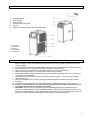
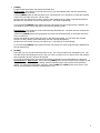
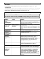
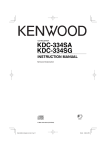
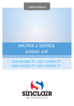
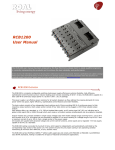
USER'S MANUAL
LOCAL AIR CONDITIONER
AMC-11AN, AMC-14AN
INTRODUCTION / TECHNICAL DATA
Congratulations on purchasing portable type air conditioner.
Your air-conditioner has been developed and manufactured in accordance with standards of state of the art
technology.
Please read the operating instructions carefully before connecting your unit to the power supply in order to
prevent damage from improper use. Pay special attention to the safety instructions. If you pass this unit on
to a third party, you must also include these operating instructions. Please keep these operating instructions
in a safe place for any questions which may arise in future.
Thank you for showing confidence in our product. We hope you enjoy a pleasant room climate with your airconditioner.
Original instructions
9
9
9
9
9
9
9
EASY TO OPERATE AND TO EASY TO MOVE AROUND
The unit can be moved easily on rollers from room to room.
The air quantity can be adjusted via up to three ventilation levels.
The air flow can be very strong and reach up to 5 or 6 metres.
Installation by a specialist is not required
Simply plug into a normal household socket with an operating voltage of 220-240V/ 50Hz.
The extract air hose can be stored in the unit for transport and when not in use.
This unit operates in accordance with the heat pump principle. On account of the special, innovative
construction of the unit, its heating function is extremely efficient compared to conventional heating units.
2
SCOPE OF DELIVERY
1 x unit
1 x remote control
1 x air hose 150 cm
1 x air hose connector
1 x bracket air hose
1 x sir outlet grid
1 x coarse filter top, 1 coarse filter
bottom
1 x operating instructions
1 x drainage hose 50 cm
2 x sealing plug
BEFORE INITIATION
1. To avoid damage, place the unit in an upright position for at least 24 hours before initiation.
2. Release the holder air hose in the unit and take out the extract air hose.
3. Fasten the air hose before initiating the unit.
4. Turn the extract air hose in the direction of the arrow 1 displayed and remove it from the unit.
5. Turn the extract air hose in the direction of the arrow 2 displayed and connect it to the unit.
6. Plug the power plug into a socket. Never pull the plug out of the socket with force using the
connection line. This can damage the power cable.
7. Since the unit emits hot air, please observe a sufficient minimum safety distance to each wall.
(Fig. 1)
8. Despite the splash water protection, you should not operate the unit in moist areas, such as
e.g. swimming baths or similar areas.
9. The colour of the unit can change slightly due to direct solar radiation.
10. The unit is equipped with a special thermal deactivation. This protects the unit from
overheating in extreme ambient conditions.
11. Please place the unit so that the air inlet is not impeded, e.g. by furniture or curtains, since this
can negatively effect the capacity.
12. Do not expose direct sunlight to shine on the unit, since it may then overheat and automatically
deactivate on account of the thermal deactivation.
3
NAME OF THE COMPONENTS
1.
2.
3.
4.
5.
6.
Operating panel
Control lamp
Air outlet grid
Air hose connection piece
Air hose
Upper condensation water outlet with rubber plug
7. Cool inlet
8. Cool Air filter
9. Hot inlet
10. Hot air filter
11. Drain pipe
IMPORTANT INSTRUCTIONS
1. Before initiation, check if the operating voltage specified on the type plate complies with the local
network voltage.
2. DO NOT BLOCK THE VENTILATION. Make sure that the air outlet and air inlet are never blocked.
3. Only operate the unit on a horizontal surface to ensure no water leaks out.
4. The unit must not be operated in an area with explosive and caustic substances.
5. Clean the air filter regularly. A contaminated air filter reduces capacity.
6. Please wait at least 5 minutes after switching off the unit before switching it back on, to ensure the
compressor is not damaged.
7. The compressor of the unit has a power demand of at least 7 amps. Do not use any extension
cable with this unit.
8. The unit is designed for the cooling, heating and dehumidification of inside rooms. Other use is
excluded.
9. If the power cable is damaged, it must be replaced by a qualified specialist for safety reasons.
10. The unit is not intended for non stop cooling, for proffessional use and for cooling in winter
in technical rooms, like for example server rooms.
11. CAUTION! This unit may only be used by persons (including children) with reduced physical,
sensorial or mental capacity or with insufficient experience and lack of specialist know-how, if such
persons are supervised by a person responsible for their safety or who has been trained in the use
of the unit. Children should be supervised to ensure they do not play with the unit.
4
OPERATING PANEL
DESCRIPTION OF FUNCTIONS
1.
[POWER]
Press this switch to switch on or off
2.
[FUNC]
Press this switch to select between the functions “Cooling”, „Heating“ or „Dehumidity“
3.
[TEMP+]
Press this switch in the cooling function in order to set the required room temperature by 1°C
respectively up to a maximum temperature of 30°C.
Press this switch in the heating function in order to set the required room temperature by 1°C
respectively up to a maximum temperature of 25°C
4.
[TEMP-]
Press this switch in the cooling function in order to set the required room temperature by 1°C
respectively up to a minimum temperature of 17°C.
Press this switch in the heating function in order to set the required room temperature by 1°C
respectively up to a minimum temperature of 15°C
5.
LED-DISPLAY
The display shows the required target temperature.
By pressing the [TEMP+] or. [TEMP-] switch, the required target temperature is briefly displayed. On
pressing the [TIMER] switch, the number of hours is briefly shown until activation or deactivation. After
each manual setting, the display automatically shows the required target temperature. In the
dehumidification function, “DH” is shown in the display. Error messages are also shown in the display.
5.
[SPEED]
Press this switch to set the ventilation speed to “LOW”, “MID” (middle), “HI” (high) or “AUTO”
(automatic). If “AUTO” is selected, the ventilator operates at temperature differences larger than 9
degrees at top speed. If the temperature reduces to a difference smaller than 4 degrees, the ventilator
switches to middle blower position. If the temperature reduces further until the target temperature, the
ventilator switches to the lowest blower position.
5
7.
[TIMER]
Programmable time switch with start and residual time
Starting time: This function is used to switch on the unit automatically when the time entered has
expired. Proceed as follows:
i) Press [TIMER] switch in Stand-by (this unit is connected but not in operation), to enter the required
number of hours after which the unit is to start.
ii) Select the required function (cooling, heating, dehumidification) and set the required temperature.
iii) When the set number of hours has expired, the unit starts automatically.
If you press the [POWER] switch before the time has expired, the time programming is deleted. The
unit switches on and can be operated in the required operating mode.
Residual time: This function is used to automatically deactivate the unit when the time entered has
expired. Proceed as follows:
i) Press the [TIMER] switch during operation and enter the required number of hours after which the
unit is to switch off.
ii) After the flashing of the number of hours on the LED has stopped, you can select the required
function (cooling, heating, dehumidification) and the required temperature.
iii) When the set number of hours has expired, the unit switches on automatically.
If you press the [POWER] switch before the time has expired, the Timer programming is deleted and
the unit switches off.
8.
[SLEEP]
Using this key you can set the sleep function of the unit. The microprocessor integrated in the unit
will raise the pre-set temperature by 2°C per hour up to a maximum of 4°C after 2 hours and maintain
this temperature until the set time has expired..
If you use the sleep function, first set the time switch to the set hours as described in the functions
Residual time or Starting time. Then press the [TIMER] switch until the required hours appear on the
display. After the hour display, the display switches automatically to the previous set temperature
display. To change the temperature, press the switch [TEMP+] or [TEMP-]. With each press on the
switch, the temperature increases or decreases by 1°C.
6
COOLING
9
9
It is recommended to start the unit early on hot days, thus avoiding heating up of the room.
This unit has a self-evaporation function for condensation water, so that it is normally not necessary to
empty the water tank in cooling mode. The drainage hose need not be connected. Please make sure that
the outlet is closed with the rubber cap during operation.
(This does not apply in the case of high air humidity. If the unit operates in cooling mode for a longer period and especially at a time
of year with high air humidity, the condensation tank may be full. The control lamp will remind you to empty the water. Refer to error
message E4. In such a case, empty the water tank via the condensation water outlet. If continuous high air humidity is likely, it is
recommended to drain the condensation continuously via the drainage hose.)
COOLING IN INDOOR OPERATION
The unit stands in the room to be cooled.
Connect the air hose and the air outlet grid to the unit as displayed in the illustration; the air hose
connection piece and air outlet grid need to be exchanged.
The warm extract air must be emitted from the room via the air hose. This can be executed e.g. via a tilted
window, a door or wall aperture. Make sure that no warm outside air can enter the room. For effective
cooling, we recommend our selection of various accessories which reduce or prevent entry of warm air into
the room.
Place the function to “COOLING”. Set the target temperature using the temperature control. The settable
temperature range is between 17 and 30 degrees target temperature. The unit must only be used in an
ambient temperature of maximum 32°C.
Note: After switching on, or over, the ventilator operates, but the compressor only starts after the control lamp has flashed for three
minutes. Cooling effect may require a further 10 minutes. Further information is available under the item, “Troubleshooting”.
COOLING IN OUTDOOR OPERATION
The unit is outside the room to be cooled.
Connect the air hose and the air outlet grid to the unit as displayed in the illustration; the air hose
connection piece and air outlet grid need to be exchanged.
Place the unit in the shade if possible and in a cool place in order to increase efficiency and to avoid
overheating. At an ambient temperature of over 32 degrees, the unit may deactivate. If this occurs
continuously, we recommend you temporarily use the INDOOR OPERATION of the unit. We recommend
that a drainage hose for condensation water be connected.
7
Set the function to “COOLING”. The settable temperature range is between 17 and 30 degrees. This can be
set using the temperature control.
The air with high oxygen content cooled by the unit is fed into the room via the air hose. This can be
executed e.g. via a tilted window, a door or wall aperture. Make sure that no warm outside air can enter the
room. For effective cooling, we recommend our selection of various accessories which reduce or prevent
entry of warm air into the room, or via the remote control.
Using the “Comfort Control Kits” you can also control the unit from inside using the remote control. The
“Comfort Control Kit” set is additional accessories. It is possible to buy it at the seller or supplier.
After switching on, or over, the ventilator operates, but the compressor only starts after the control lamp has flashed for three minutes.
Cooling effect may require a further 10 minutes. Further information is available under the item, “Troubleshooting”.
HEATING
9
9
9
On cold days it is recommendable to start the unit early in order to avoid intensive cooling of the room.
For the heating function and to improve the heating effect and avoid lower temperatures (lower than
17°C) we recommend you remove the rubber plug from the condensation water outlet and allow the
condensatation water to leak out of the unit using the drainage hose. However, the drainage hose does not
have to be connected in the heating mode, Please make sure that the condesnation water outlet is closed
with the rubber cap during operation. In such a case, proceed analogously to the emptying of the water tank
in the cooling function.
The heating function of the unit must not be operated at a room temperature of more than 23°C or less
than 7°C. The unit can also be operated with heating function, if the outside temperature is lower than 7°C.
However, you must then ensure that the unit is operated inside and the room temperature is at least 7°C.
Caution: In the heating mode, separate setting of the ventilator is not provided, since the
highest ventilation level is already preset to avoid overheating of the unit.
HEATING IN INDOOR OPERATION
The unit is in the room to be heated.
Caution: Connect the air hose and the air outlet grid to the unit as displayed in the
illustration; the air hose connection piece and air outlet grid need to be exchanged.
The cold extract air has to be fed out of the room via the air hose. This can be executed e.g. via a tilted
window, a door or wall aperture. Make sure that no warm outside air can enter the room. For effective
heating, we recommend our selection of various accessories which reduce or prevent entry of cold air into
the room.
Set the function to “Heating”. The settable temperature range is between 15 and 25 degrees target
temperature. You can set this using the temperature control.
After switching on, or over, the ventilator operates, but the compressor only starts after the control lamp has flashed for three minutes.
Cooling effect may require a further 10 minutes. Further information is available under the item, “Troubleshooting”.
8
HEATING IN OUTDOOR OPERATION
The unit is outside the room tio be heated. Outdoor operation is ideal for the transition period in which
outside temperatures do no fall below 7 degrees. (If the outside temperature should however fall below 7 degrees
continuously, we recommend indoor operation). Connect the air hose and the air outlet grid to the unit as
displayed in the illustration, or the air hose connection piece and air outlet grid need to be exchanged.
Set the function to “Heating”. The settable temperature range is between 15 and 25 degrees target
temperature. You can set this using the temperature control.
The air with high oxygen content heated by the unit is fed into the room via the air hose. This can be
executed e.g. via a tilted window, a door or wall aperture. Make sure that no warm outside air can enter the
room. For effective heating, we recommend our selection of various accessories which reduce or prevent
entry of cold air into the room.
Using the “Comfort Control Kit” you can also control the unit from inside using the remote control. The
“Comfort Control Kit” set is additional accessories. It is possible to buy it at the seller or supplier.
After switching on, or over, the ventilator operates, but the compressor only starts after the control lamp has flashed for three minutes.
Cooling effect may require a further 10 minutes. Further information is available under the item, “Troubleshooting”.
DEHUMIDIFICATION
Humidity is extracted from the air, collected in the water tank and discharged via the condensation water
outlet. Only air the room if the humidity of the outside air is below that in the inside room. Set the function to
“Dehumidity”.
Caution: In the dehumidify mode, separate setting of the ventilator is not provided, since
the lowest ventilation level is already preset to ensure efficient dehumidification of ambient
air.
The rubber plug of the condensation water outlet is removed and a drainage hose attached. To collect the
condensation water easily in a tank, a drainage hose is included in the scope of delivery which you can
connect to the upper condensation water outlet. Allow water to flow out continuously in order to achieve
higher dehumidification capacity. In the dehumidify mode, you must not feed the room air outside with the
extract air hose.
9
CLEANING AND MAINTENANCE
MAINTENANCE
PLEASE REMOVE THE POWER PLUG FROM THE SOCKET BEFORE CLEANING THE UNIT.
COARSE FILTER
The air filters on the side of the unit can be simply removed by pulling the frame sidewards. When cleaning,
use a vacuum cleaner with brush or wash the filters under running, warm water and dry them with a soft
cloth!
Please clean the coarse filters before initial use, and regularly when in use.
ERROR MESSAGES
The local air conditioner is equipped with a 3-minute compressor-delay system which means the
compressor needs 3 minutes to start.
This affects the switching on of the unit (POWER) as well as switching over from one function to
the next, e.g. dehumidify to cooling or heating.
ERROR/
PROBLEM
Can I switch the
unit on
immediately after
unpacking it?
CAUSE
When switching
on the unit I sense
a smell. What
should I do.
Production-related
cause or incorrect
storage of unit at e.g.
dusty areas.
Can I operate the
unit WITHOUT the
extract air hose.
At which intervals
should the
activated carbon
filter of the unit
be replaced?
How can I
increase the
efficiency of the
unit?
Compressor does
not activate
unit deactivates.
How is the m² or
m³ data of the
manufacturer
calculated
REMEDY
No.
The unit must be placed upright for at least 24 hours
after every transport. Otherwise the compressor may be
damaged and there is no capacity.
Odour development can arise on first use and after a
longer period of non-use by storing in unsuitable areas
(e.g. dusty areas).
Run the unit for ½ a day. The smell will disappear after a
while. In the case of intensive odour development, air the
room.
No.
To achieve temperature adjustments, surplus heat or
coldness must be discharged.
To use the purpose of the filter fully, it should be
replaced every 6 months.
External circumstances exist which may impact the
efficiency of the unit. Room insulation, use of
wall/window adapter, ratio of window space (solar
radiation), operation of electrical units in the room (EDP),
presence of several persons in the room. You can
increase the efficiency of the unit accordingly by
adjusting such circumstances.
Depending on ambient temperatures and unit type it may
take approx. 10 minutes after starting the compressor
until the cooling/heating capacity is reached.
On reaching the set required temperature, the unit
switches off automatically.Check manual setting of the
required temperature as well as the TIMER setting.
The m² or m³ data of the manufacturer for the various
units are average values related to a room height of 2.5
metres. It must be considered that such data can be
clearly underscored or exceeded under certain
circumstances. Circumstances which work against
efficiency of the units include e.g. bad insulation of the
building, large window areas, south facing, attic
apartment, many additional heat sources, such as e.g.
number of persons, EDP, light, kitchen units, washing
units etc.
10
Unit does not cool
correctly
E1
E2
Room temperature
outside the function
range:
Room temperature
inside the function
range:
Temperature of the
cooling agent lines too
high or too low
E3
Incorrect signal
E4
Water tank full
DF
Defrosting mode
Switching the
units from °F to °C
and viceversa.
Solution
You achieve the most effective and economical cooling
comfort if you already cool the room to be cooled when
the room temperature is not yet heated up. Air
conditioners operate more effectively if the temperature
is to be maintained. To drastically cool the air and
inventory in a fully heated room requires much more time
and energy.
Observe all data in these operating instructions
concerning function range.
New measurement of start temperature. Please switch
the unit off and start it again after approx. 30 minutes. If
the error occurs continuously, the unit requires specialist
inspection.
Temporary error on measuring output temperature.
Please switch the unit off and start it again after approx.
30 minutes. If the error occurs continuously, the unit
requires specialist inspection.
This error message in the cooling function refers to too
high ambient temperatures, and in the heating function
to too low ambient temperatures. Please observe the
instructions relating to ideal operation of the unit. This
may also be a temporary error measurement between
the start and output temperature. Please switch the unit
off and start it again after approx. 30 minutes. If the error
occurs continuously, the unit requires specialist
inspection.
If the water tank is full, the warning sign "E4" appears in
the display. To restart operation of the unit, please
remove the plug of the condensation water outlet to
allow water to leak out. Please use an appropriate
collection tank. When the water has been completely
removed, please start the unit again. The unit can now
be used as usual.
This procedure is completely normal and protects the
system from icing and failure. The unit starts
automatically after approx. 15 minutes again (depending
on the function setting). This procedure repeats itself
regularly.
Please switch off the unit to STAND-BY mode by
pressing the button POWER on the unit (the unit is
plugged in). Hold for 5-10 seconds button FUNC on the
unit and after a beep sound switch on the unit by button
POWER.
11
WIRING DIAGRAM
ENERGY LABEL
12
TECHNICAL PARAMETERS
Category
Local air conditioner
Model name
Description
AMC-11AN
Symbol
Value
Unit
Rated capacity for cooling
Prated for cooling
3,0
kW
Rated capacity for heating
Prated for heating
3,0
kW
Rated power input for cooling
PEER
1,2
kW
Rated power input for heating
PCOP
1,0
kW
Rated Energy efficiency ratio
EERd
2,6
-
Rated Coefficient of performance
COPd
3,1
-
Power consumption in thermostat-off mode
PTO
91,1
W
Power consumption in standby mode
PSB
0,47
W
Electricity consumption for cooling
QSD
1,1
kWh / h
Electricity consumption for heating
QSD
0,8
kWh / h
Sound power level
LWA
62
dB(A)
GWP
2088
kg ekv. CO2
Global warming potential
Energy class
cooling / heating
A / A++
-
type * / weight
R410A / 0,49
/ kg
area
15 - 25
Voltage
-
~ 220 - 240
V
Frequency
-
50
Hz
Refrigerant
Optimal room size
m
2
Rated current
-
5,8
A
Rated air flow
-
400
m /h
Hose for hot air
length / diameter
125 / 15
cm
Dehumidifying
-
50,0
litres / day
3
Dimensions of product
(w x h x d)
300 x 778 x 505
mm
Dimensions of package
(w x h x d)
550 x 815 x 330
mm
Weight of product
-
28,6
kg
Weight with package
-
30,7
kg
Name and address of the manufacturer
or of its authorised representative.
Contact details for obtaining more information
Manufacturer: SINCLAIR CORPORATION Ltd., 1-4 Argyll St., London, UK
Representative: NEPA spol. s r.o., Purkyňova 45, Brno 612 00, ČR
www.sinclair-eu.com / [email protected]
* R410A (50% HFC-32, 50% HFC-125)
* Contains fluorinated greenhouse gases covered by the Kyoto Protocol.
13
TECHNICAL PARAMETERS
Category
Local air conditioner
Model name
Description
AMC-14AN
Symbol
Value
Unit
Rated capacity for cooling
Prated for cooling
4,0
kW
Rated capacity for heating
Prated for heating
4,0
kW
Rated power input for cooling
PEER
1,5
kW
Rated power input for heating
PCOP
1,3
kW
Rated Energy efficiency ratio
EERd
2,6
-
Rated Coefficient of performance
COPd
3,1
-
PTO
91,4
W
Power consumption in thermostat-off mode
Power consumption in standby mode
PSB
0,4
W
Electricity consumption for cooling
QSD
1,5
kWh / h
Electricity consumption for heating
QSD
1,3
kWh / h
Sound power level
LWA
63
dB(A)
GWP
2088
kg ekv. CO2
Global warming potential
Energy class
cooling / heating
A / A++
-
type * / weight
R410A / 0,605
/ kg
area
25 - 35
Voltage
-
~ 220 - 240
V
Frequency
-
50
Hz
Refrigerant
Optimal room size
m
2
Rated current
-
7,7
A
Rated air flow
-
450
m /h
length / diameter
125 / 15
cm
litres / day
Hose for hot air
Dehumidifying
3
-
70,0
Dimensions of product
(w x h x d)
300 x 778 x 505
mm
Dimensions of package
(w x h x d)
550 x 815 x 330
mm
Weight of product
-
30,6
kg
Weight with package
-
32,8
kg
Name and address of the manufacturer
or of its authorised representative.
Contact details for obtaining more information
Manufacturer: SINCLAIR CORPORATION Ltd., 1-4 Argyll St., London, UK
Representative: NEPA spol. s r.o., Purkyňova 45, Brno 612 00, ČR
www.sinclair-eu.com / [email protected]
* R410A (50% HFC-32, 50% HFC-125)
* Contains fluorinated greenhouse gases covered by the Kyoto Protocol.
14
NOTE CONCERNING PROTECTION OF ENVIRONMENT
This product must not be disposed of via normal household waste after its service life, but
must be taken to a collection station for the recycling of electrical and electronic devices. The
symbol on the product, the operating instructions or the packaging indicate such disposal
procedures. The materials are recyclable in accordance with their respective symbols. By
means of re-use, material recycling or any other form of recycling old appliances you are
making an important contribution to the protection of our environment. Please ask your local council where
your nearest disposal station is located.
INFORMATION CONCERNING USED REFRIGERANT MEDIUM
This unit is containing fluorinated gases included in the Kyoto protocol. The maintanance and the liquidation
must be carried out by qualified personel.
Type of refrigerant: R410A
The composition of the cooling medium R410A: (50% HFC-32, 50% HFC-125)
The quantity of the refrigerant: please see the unit label. Hermetically sealed system.
The value GWP: 2088
GWP = Global Warming Potential
In case of quality problem or other please contact your local supplier or authorized service center.
Emergency number: 112
PRODUCER
Producer: SINCLAIR CORPORATION Ltd., 1-4 Argyll St., London W1F 7LD, UK, www.sinclair-eu.com
This product was manufactured in China (Made in China).
REPRESENTATIVE AND TECHNICAL SUPPORT
NEPA spol. s r.o.
Purkyňova 45
612 00 Brno
Czech Republic
Tel.: +420 800 100 285
www.nepa.cz
15