1
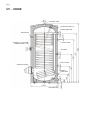
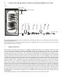
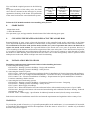
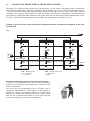
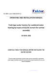
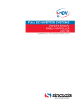
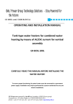
INSTRUCTIONS ENAMELED INDIRECT WATER HEATERS ST-300DE H E AT P U M P S Please read this manual carefully before installing the heater! Dear Customer, Sinclair Corporationt Ltd. thanks you for your decision to use a product of our brand. The manufacturer reserves the right to modify the product. This product is designed for permanent contact with drinking water. Table of Contents 1. 2. 3. 4. 5. 6. 7. 8. 9. 10. 11. Application Product Description Important Cautions Commissioning of the Heater Specifications and Description of the Heater Connecting the Heater to the Hot Water Distribution System Safety Fittings Spare Parts Cleaning the Heater and Replacing the Anode Rod Installation Regulations Connecting the Heater to the Heating System 2 2 3 3 4 5 5 6 6 6 7 Operating Conditions: We recommend to use this product in an indoor environment with air temperatures from +2°C to +45°C and a relative humidity of maximum 80%. 1. APPLICATION The ST-300DE indirect stationary heater is designed to prepare the hot water in connection with a heat pump. Additional heating can be done by electric heating element TJ 6/4". 2. PRODUCT DESCRIPTION The heater tank is welded from a steel sheet and the entire tank is protected by a hot water resistant enamel. As an additional protection against corrosion, a magnesium anode rod is installed inside the tank. This rod changes the electrical potential inside the tank and thus reduces the effects of corrosion. Inside the tank, there is welded a helical heat exchanger that is made of steel pipes with an outside enamel coating, hot water, cold water and circulation connections and thermostat socket. The tube heat exchanger is intended only for the heating circuit. On the heater side, there is a cleaning and inspection opening with flange cover (flange inside diameter is 110mm) secured by eight M8 bolts with 150mm spacing. The heater has also a G 1½" opening for screwing an auxiliary heating element. This option is used to heat up water in the upper part of the heater to the required temperature, when the heater is connected to a heat pump system. The tank is insulated with 50mm or 60mm polyurethane CFC-free foam; heater case is made of plastic. 3. IMPORTANT CAUTIONS Warranty card is invalid without certification from a professional firm, which confirms the electrical installation and plumbing. Check the protective Mg anode regularly and replace it if needed. No stop valve can be put between the heater and safety valve. All hot water outputs must be fitted with a mixing battery. Before filling the heater with water for the first time, it is recommended to tighten the nuts on the flange connection of the tank. 4. COMMISSIONING OF THE HEATER After connecting the heater to the water distribution system, hot water heating system, and eventually to the electrical network, and after checking the safety valve (according to the instructions attached to the valve), the heater may be put into operation. Procedure: a) Check the plumbing and electrical installation including the connection to the hot water heating system. Check the proper placement of both operational and safety thermostat sensors. The sensors must be inserted all the way in the socket; first the operational thermostat and then the safety thermostat. b) Open the hot water valve on the mixing battery. c) Open the valve on the cold water inlet to the heater. d) When the water starts to flow through the hot water valve, the heater is filled up and the valve should be closed. e) Should a leakage (of the flange cover) occur, we recommend to tighten the bolts of the flange cover. f) When heating the sanitary water using the thermal energy from the hot water heating system, switch off the electricity and open the valves on the inlet and outlet of heating water, eventually bleed the heat exchanger. When commencing operation, flush the heater until the cloudiness disappears. g) Fill properly the warranty card. 5. SPECIFICATIONS AND DESCRIPTION OF THE HEATER Table 1 1 Type Storage volume Height of the heater Diameter of the heater Max weight of the heater Max working pressure in the tank Max working overpressure in the exchanger Max heating water temperature Max hot water temperature Exchanger heating surface Exchanger volume Standing heat loss l mm mm kg MPa MPa °C °C m2 l W ST-300DE 286 1580 670 138 1 1 110 90 3,2 24 72 Fig. 1 ST – 300DE Hot water outlet Protective anode rod Heating water inlet Thermometer Opening G 1½" for electric heating element TJ 6/4" Sensor socket Circulation Sensor socket Inspection opening Heating water outlet Cold water inlet 6. CONNECTING THE HEATER TO THE HOT WATER DISTRIBUTION SYSTEM Fig. 3 Mixing valve Hot water output Stop valve Drain valve Manometer Control valve Stop valve Safety walve with check valve Expansion tank Drain valve Cold water Cold water input The cold water inlet of the heater must be fitted with a T-fitting with a drain valve to discharge water from the heater if needed (see Section 11). Each heater that can be individually blocked must also be equipped with a test valve, check valve, safety valve and pressure gauge at the hot water inlet. 7. SAFETY FITTINGS Each pressure hot water heater must have a membrane spring-loaded safety valve. Nominal clearance of safety valves is determined according to ČSN 06 0830 standard. Heaters are not equipped with a safety valve. The safety valve must be easily accessible and as close to the heater as possible. The inlet pipe must have at least the same clearance as the safety valve. The safety valve must be placed high enough to ensure dripping water drain by gravity. We recommend to mount the safety valve onto a branch pipe. This allows you to easier replace the valve without having to drain the water from the heater. Safety valves with fixed pressure set by the manufacturer are used for the assembly. The opening pressure of the safety valve must be identical to the maximum allowed heater pressure, and at least 20% higher than the maximum pressure in the water distribution system. If the pressure in the water distribution system exceeds this value, a reduction valve must be included in the system. No stop valve can be put between the heater and safety valve. Follow the installation manual provided by the manufacturer of the safety valve. Safety valve must be checked each time before putting it into operation. The check is performed by manual moving of the membrane away from its seat by turning the knob of the releasing device always in the arrow direction. After being turned, the knob must click back into a notch. The proper function of the releasing device results in water draining through the safety valve drain pipe. If the releasing device functions properly, water runs off the safety valve drain pipe. In normal operation, it is necessary to perform this check at least once a month and each time, when the heater was shut down for more than 5 days. Water may be dripping from the safety valve drain pipe; the pipe must be opened into the air, pointed down and placed in an environment where the temperatures does not drop below the freezing point. When draining the heater, use the recommended drain valve. First, close water inlet of the heater. You can find the required pressures in the following table. For proper operation of the safety valve, the check valve must be mounted on the inlet pipe to prevent spontaneous draining of the heater and penetration of hot water back into the water distribution system. Opening pressure of the safety valve(MPa) 0,6 0,7 1 Max allowable working overpressure of the water heater(MPa) 0,6 0,7 1 Max pressure in the cold water piping (MPa) do 0,48 do 0,56 do 0,8 Follow the ČSN 06 0830 standard when installing safety devices. 8. SPARE PARTS - Magnesium anode - Contact thermometer Give part name, type, and type number from the heater label when ordering spare parts. 9. CLEANING THE HEATER AND REPLACING THE ANODE ROD Repeated heating of water causes a limescale deposition on the enamelled tank surface and mainly on the flange cover. Deposition depends on the hardness of heated water, its temperature, and the amount of hot water consumed. We recommend to check the tank and the anode rod after two years of operation and remove the limescale or replace the anode rod if needed. The expected lifetime of the anode rod is two years of operation; however, it varies according to the hardness and chemical composition of the water at the place of use. Based on this inspection, it is possible to schedule the next replacement of the anode rod. Call a service company to clean the tank or replace the anode rod. When draining water from the heater, hot water valve of the mixing battery must be opened to avoid underpressure in the tank, which would prevent water from draining. 10. INSTALLATION REGULATIONS Regulations and instructions that must be followed when installing the heater: a) concerning the heating systems ČSN 06 0310 - Heating systems in buildings - Design and installation ČSN 06 0830 - Heating systems in buildings - Safety devices b) concerning the electrical systems ČSN 33 2180 - CSN electric engineering regulations. Rules for installation of electrical apparatus and appliances ČSN 33 2000-4-41 - Low voltage electrical installations - Protection for safety - Protection against electric shock ČSN 33 2000-7-701 - Electrical installations of buildings - Requirements for special installations or locations Locations containing a bath or shower c) concerning the hot water heating systems ČSN 06 0320 - Heating systems in buildings - Generation of domestic hot water - Designing ČSN 06 0830 – Heating systems in buildings - Safety devices ČSN 73 6660 - Water supply in buildings ČSN 07 7401 - Water and steam for hot water and steam boilers with nominal steam pressure of up to 8 MPa ČSN 06 1010 - Storage water heaters with water and steam heating and combined with electric heating. Technical requirements. Testing ČSN EN 12897 - Water supply - Specification for indirectly heated unvented (closed) storage water heaters Both electric and water installations must follow and meet the requirements and regulations in the country of use. WARNING: To prevent the growth of bacteria (e.g. Legionella pneumophila) in the tank heaters, it is recommended, if inevitable, to periodically and temporarily increase the temperature of the hot water to at least 70 °C. Another way to disinfect hot water may also be applied. 11. CONNECTING THE HEATER TO THE HEATING SYSTEM The heater is to be placed on the ground next to a heating source, or in its vicinity. The heating circuit is connected to the marked inlets and outlets of the heater exchanger, and the bleeding valve is to be mounted at the highest point. It is necessary to install a filter into the heating circuit to protect the pumps, three-way valve, check valves and heat exchanger from clogging. We recommend to flush the heating circuit before the installation. All interconnecting piping must be properly thermally insulated. If the system will work with the priority heating of DHW using a threeway valve, follow the installation instructions provided by the manufacturer of the three-way valve. Example of group of heaters connected using the Tichelmann method for balanced consumption of hot water from all tanks Fig. 3 DHW output DHW DHW DHW C C C HeW inlet HeW inlet HeW inlet HeW input HeW output Thermostat socket Thermostat socket Thermostat socket HeW outlet HeW outlet HeW outlet CW CW CW HeW – Heating water CW – Cold water C – circulation DHW – Domestic hot water 1 – Check valve 2 - Pump Disposal of packaging material and non-functional product A service fee for providing return and recovery of packaging material has been paid for the packaging in which the water heater was delivered. The service fee was paid pursuant to Act no. 477/2001 Coll. as amended, at EKO-KOM a.s. Client number of the company is F06020274. Dispose of packaging material at a public waste disposal site. Uninstall the discarded and unserviceable product after the end of operation and transport it to the waste recycling centre (collecting yard), or contact the manufacturer. CW input Warranty Card Product data: Store full address and stamp: Date of sale: Type: Type number: Serial number: Production date: Professional plumbing was made by: Date of Installation: Full address, stamp, sign: Add data from the manufacturing label or stick the label. The product has passed the final technical inspection and met the following tests: Insulation resistance measurements using the test voltage of 500V. Measurement of contact resistance using current 10A at voltage 012V AC. Test using applied voltage of 1300V. Functional test with simultaneous measurement of both active and leakage currents. Tank pressure test Professional electrical installation was made by: Date of Installation: Full address, stamp, sign: WARRANTY Product replacement or withdrawal from the contract is subject to applicable provisions of the Civil Code. The product will be repaired free of charge within the warranty period, if a product defect that is not caused by user or an unavoidable event (e.g. a natural disaster) occurs. The warranty period of the product starts from the date of sale to the end customer and lasts: 5 years for the inner tank of the heater including case, thermal insulating layer and the flange cover; 2 years for electrical installation, heater element and other accessories. The warranty period for replacement parts is 24 months. 1. Conditions for a warranty claim: The warranty card must be properly filled out (with a confirmed date of sale) Installation of the product must be performed by an authorized person (confirmed in the warranty card). The buyer is obligated to familiarize himself with the relevant installation and operational instructions before putting the product into operation. 2. Termination of Warranty: If the customer did not meet the conditions of point 1. If any repair during the warranty period was not performed by the seller nor its authorized service partner. If the product defect was obviously caused by improper installation or use of the product. If the product was not being used according to installation and operational instructions given by the seller or manufacturer. If any unauthorized modifications or construction changes of the product have been made. If the production label with serial number is damaged or missing. 3. Service: Warranty and after-warranty repairs are provided by the seller: SINCLAIR CORPORATION Ltd. 1-4 Argyll St., London, UK using its own service centre, or through contractual or authorised contractual service partners. 4. Warranty claim procedure: End customer will report the type of defect, serial number, type number, date of purchase of the product (from the warranty card) and brief description of the problem to its contractual service partner or directly to the seller. The customer will wait for a technician, who will fix the defect or take another necessary measures to settle the claim. Never uninstall the product from the system (it is important to assess the defect)! In the case of unjustified claim, the customer will be charged directly for the claim-related costs. 4-2014 Manufacturer: Sinclair Corporation Ltd., 1-4 Argyll Street, London W1F 7LD, UK Supplier and technical support: Nepa, spol.s.r.o. Purky ova 45 612 00 Brno Czech Republic www.nepa.cz Toll-free info line: +420 800 100 285