1
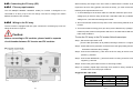
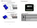
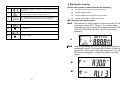
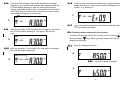
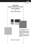
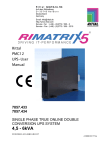
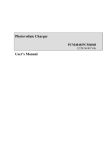
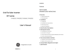
Contents
1
2
3
Grid Tie Solar Inverter
EnerSolis Series
ES 6000
ES 8000
ES 10000
ES 12000
Foreword...........................................................................................................2
IMPORTANT SAFETY INSTRUCTIONS ..........................................................3
Overview ...........................................................................................................6
3.1
External dimensions ...........................................................................6
3.2
External features ................................................................................7
4
Installation .........................................................................................................8
4.1
Unpacking ..........................................................................................8
4.2
Installation requirements ....................................................................9
4.3
Mounting the unit .............................................................................. 11
4.4
Electrical installation .........................................................................14
5
Front display panel .........................................................................................21
6
Starting the inverter ........................................................................................23
6.1
Start-up and operation test ...............................................................23
6.2
Checking values measured by the inverter ......................................25
6.3
Inverter status indicators ..................................................................29
7
Communication interfaces ..............................................................................30
7.1
Standard communication interfaces .................................................30
7.2
Optional communication card ...........................................................32
8
Remotely Communication ..............................................................................37
9
Inverter status diagnostics and repair.............................................................38
10 Specifications ..................................................................................................41
11 Contact ...........................................................................................................43
Three-Phase , 6 / 8 / 10 /12 kW
User’s Manual
VERSION 1.1
1
1 Foreword
2 IMPORTANT SAFETY INSTRUCTIONS
Thank you for purchasing the EnerSolis ES 6000(ES 8000/ES
10000/ES 12000) Grid Tie Solar Inverter. Many years of experience
■General
Warning! Incorrect operation and work performed
incorrectly can cause damage and serious injury! Only
qualified staff are authorized to install your inverter, and
only within the scope of the respective technical
regulations. Do not start operation or carry out
maintenance work before you have read the chapter
“Safety Regulations“!
in the design of power devices have gone into the construction of
this device. We hope that it will give your solar power system many
years of trouble-free operation. However, the inverter is a complex
electronic system which is confronted with a wide variety of local
conditions, so if questions arise or a malfunction occurs do not
hesitate to call your specialized dealer for assistance.
Please read this user's guide carefully to familiarize yourself with the
device, paying special attention to the information on installing and
commissioning the device.
This manual contains important instructions for the ES
6000(ES 8000/ES 10000/ES 12000) that must be followed
during installation and maintenance of the inverter.
Warning! These servicing instructions are for use by
qualified personnel only. To reduce the risk of electric
shock, do not perform any servicing other than that
specified in the operating instructions unless you are
qualified to do so.
■Housing
Only qualified installers are authorized to open the
connection area. Do not open the connection area when
the inverter is connected to power.
Only well-trained service staff may open the upper
portion (power stage) of the inverter, and only when it is
not connected to power.
2
3
■Warning
■Repair
Below warning symbols are described according to related
sections:
Only well-trained service staff are authorized to carry out
repairs to the inverter.
Symbol
Description
■Solar panels
Before connecting the solar panels (also called photovoltaic
Caution, risk of electric shock !
(PV) modules), you must check whether the voltage parameters
specified in the manufacturer’s data correspond with the actual
parameters. When checking the voltage please take into
account that solar modules supply a higher no-load voltage
Caution, risk of danger !
when temperature is low and sunlight level remains unchanged.
At
Caution , hot surface !
The PV inverter surface temperature
of the casing can exceed +70 °C .
4 °F ( -20 °C) the open-circuit voltage of the PV modules
must never exceed 1,000 V. The data sheet of the solar module
will include the temperature factors applicable for ascertaining
the theoretical open-circuit voltage at
4 °F ( -20 °C) . If the
solar modules exceed an open-circuit voltage of 1,000 V the PV
inverter might be damaged, which will void the warranty.
Caution, risk of electric shock
Energy storage timed discharge !
Refer to the operating instructions !
The PV inverter includes a residual current monitoring unit
(RCMU) according to VDE0126-1-1. This device measures the
ground current of the PV array and prevents the inverter from
feeding the grid in case of a ground fault.
■Grid connection
Only appropriately licensed contractors are authorized to
connect the PV inverter to the grid. Consult your local
authorities for specific requirements. Before connecting the PV
inverter to the grid, permission for the connection must be
granted by the utility company.
4
5
3.2 External features
3 Overview
3.1 External dimensions
Model
number
ES 6000
ES 8000
ES 10000
ES 12000
W
451
451
451
451
2. Solar array input: plug-and-play connectors for the solar modules
H
595
595
595
595
3. Standard communication ports: EPO, RS-232, and RS-485
D
247
247
247
247
4. Optional communication slot: USB, RS-485, Dry-Contact, TCP/IP, or WiFi。
Dimensions (mm)
1. LCD and LED display: Shows operation information and status.
5. AC output terminal: AC output for the utility supply
6. DC input switch: switches the PV string inputs on and off
6
7
4.2 Installation requirements
4 Installation
Warning: Be sure to read the safety instructions on pages 3 and 4 before
installing the PV inverter.
The PV inverter is heavy. Take this weight into account
when choosing the installation site and method of
installation.
4.1 Unpacking
Inspect the PV inverter upon receipt. The packaging is robust, but accidents and
damage may still occur during shipment. Notify the forwarder and dealer if there is
damage.
To ensure proper operation and long operating life,
position
the
inverter
according
to
the
following
requirements:
The packaging is recyclable and reusable.
After removing the inverter from the carton check for the following standard
package contents, in addition to the inverter itself.
(1) ES 6000(ES 8000/ES 10000/ES
12000) are designed to comply with
accessories set (cover, PV connector)
Index of Protection class 65, which
CD-ROM
allows units to be installed in outdoor
A wall mount kit set (backrest and backplane positioning paper)
and wet environment . The PV
inverter is designed for outdoor
installation. It should be installed in a
place here it is not exposed to direct
sunlight. The yield of the PV system
may
be
reduced
at
increased
ambient temperatures or when installed in poorly ventilated and warm indoor
locations. We recommend an ambient temperature range of -20°C to +60 °C .
8
9
(2) The PV inverter is designed to be mounted on a vertical wall. If installing the
4.3 Mounting the unit
unit outdoors make sure that it is not slanting forward.
We advise against installing the unit in a horizontal position outdoors.
For vertical installation and installation on solid concrete or block walls, when
selecting the mounting hardware be sure to take into account the weight of the PV
inverter.
(3) When choosing the installation site ensure that there is enough space for
heat dissipation. Under normal conditions the following clearance guidelines
should be applied:
The procedure for mounting the inverter is described on the following page.
10
11
4.3.1 Using the mounting bracket
Method II: Use screws to fix the unit
Step 1. Mark the positions to drill the holes and setting screw.
Method I: Use the backplane to fix the unit
Step 1. Put the backplane position paper on the intended spot of the wall.
Drill holes based on the diameter of the backplane to fix holes. Finally
, fix the backplane on the wall.
Step 2. Screw the nut on the sleeve without fastening.
Step 2. Hang the PV inverter on the wall that it cannot be moved sideways.
Step 3. Hang the PV inverter on the backplane. Make sure that it holds the
inverter unit firm and securelyFinally, fastening the nut.
Step 3. Make sure that the PV inverter is positioned securely on the bracket.
12
13
4.4 Electrical installation
4.4.1 Connecting to the grid (AC utility)
Caution ! Risk of electric shock !
■ Make sure the AC breaker or switch installed between the
PV Inverter and the grid (AC Utility).
Note:Please use Ue: 690Vac / Ie:25A circuit breaker.
Caution:
Before connecting to Grid(AC utility),please install a separate
circuit breaker between inverter and Grid
■ Make sure the DC breaker or switch installed between the
PV Inverter and the PV array.
To connect the AC power cable proceed as follows:
Note:Please use Ue: 1000Vdc / Ie:25A circuit breaker.
■ When working on the PV inverter, disconnect the AC breaker or
switch and DC breaker or switch.
■ Make sure that the AC breaker or switch and DC breaker or
Step 1. Measure the grid’s (i.e., the utility’s) voltage and frequency. The voltage
and frequency of the inverter are set at the factory to match the utility in
the country where the product will be delivered.
Step 2 .Before wiring the PV inverter ensure that the main breaker in the primary
switch cannot be unintentionally closed during installation and
utility breaker box is switched OFF. Switch this breaker ON only after all
commissioning works.
wiring is completed as instructed below.
The electrical connections for the PV inverter are shown in Figure 1.
Step 3 .Remove the screws that secure the wire terminal cover, and carefully
remove the cover. Alternatively, remove the connector as shown in
Figure 2.
Figure 2
Figure 1
14
15
Step 4. Insert the utility cable through the cable gland. Connect the wires to the
terminal block as shown in Figure 3.
4.4.2 Status identification of the DC input switch
Before operating the DC input switch, make sure of status identification as below
instructions .
Turn the DC switch
90° to the on position (position I ) shown in Figure 4
Turn the DC switch 180° to the off position (position 0 ). shown in Figure 5
Figure 3
Figure 4
Figure 5
Step 5. Reattach the cover, and evenly tighten the four screws.
Warning: To prevent risk off electric shock ensure that the ground
(PE) wire is properly earthed before operating the PV
inverter.
Suggested AC cable width
2
Model
Area (mm )
AWG no.
ES 6000
> 2.1
< 14
ES 8000
> 2.1
< 14
ES 10000
> 3.5
< 12
ES 12000
>3.5
<12
16
17
4.4.3 Connecting the PV array (DC)
When matching PV strings to the PV inverter, to determine the number of panels
4.4.3.1 PV array requirements
required in each PV string (panels connected in series), you must ensure that the
The ES 6000(ES 8000/ES 10000/ES 12000) PV inverter is designed to be
following three requirements are met:
connected to an array of up to two PV strings. The two PV strings can contain
1. To avoid damage to the inverter make sure that the maximum open circuit
voltage (Voc) of each PV string is less than 1,000 VDC under any conditions.
different numbers of PV modules.
Voltage over 1,000 VDC will damage the inverter.
4.4.3.2 Wiring to the PV array
2. Do not exceed the maximum array short-circuit current rating marked on the
The PV inverter is equipped with PV quick connects for connecting up to two PV
inverter.
3. To harvest maximum energy from your array ensure that the Vmp (voltage at
strings as shown in Figure 6.
maximum power) does not drop below 450 VDC or increase above 850 VDC
under most conditions.
Caution:
Before connecting to PV modules, please install a separate
circuit breaker between PV inverter and PV modules.
To wire the PV array to the PV inverter follow these steps:
Step 1: Set the DC input switch to 0
(Turn the DC input switch to off position,referring to section 4.4.2 Figure 5)
Step 2: Check that the PV generator connectors have the right polarity and do not
exceed the maximum string voltage.
Step 3: Connect the POSITIVE (+) wire from the #1 PV string to the PV inverter’s
positive (+) terminal.
Step 4: Connect the NEGATIVE (–) wire from the #1 PV string to the PV inverter’s
negative (–) terminal.
Step 5: Connect the ground wire from the #1 PV string to earth.
Step 6: If necessary repeat steps 2 through 5 for the #2 PV string. Double-check
that the wires are in the proper locations.
Suggested DC cable width
Figure 6
18
Model
ES 6000
ES 8000
ES 10000
ES 12000
2
Area (mm )
> 4.0
> 4.0
> 4.0
> 4.0
19
AWG no.
< 12
< 12
< 12
< 12
4.4.3.3 Requirements for connection
5 Front display panel
The number of solar panels in String A
need not equal the number in String B.
For a single PV string enter settings mode
and configure for parallel operation.
Symbols on the LCD
1 LCD
○
Symbol
Description
Utility source
Inverter is working in specified mode.
Solar cell
Inverter operation mode flow chart
4-digit measurement display
Figure 7. DC connections for a two-string PV array
20
21
6 Starting the inverter
LED Indicators
Before the inverter is started ensure the following:
2
○
Red LED shines steadily to indicate a ground fault or DC input
isolation fault.
3
○
Yellow LED shines steadily to indicate that the utility does not match
the input standard of the inverter (voltage, frequency, etc.).
4
○
Green LED shines steadily when the solar power is greater than sleep
power. It flashes when the solar power is less than sleep power.
The wire terminal cover is securely screwed on.
The AC breaker is OFF.
The DC cables (PV strings) are fully connected.
Control Keys
5
○
Special functions and log in/out
6
○
Go to next page.
7
○
Confirm change of inverter setting.
8
○
Go to previous page.
The AC (utility) cable is connected correctly.
6.1 Start-up and operation test
6.1.1
Connect the PV string voltage by switching on the DC switch,
referring to section 4.4.2. Figure 4. The inverter starts
automatically when it senses DC voltage greater than 250
VDC. All of the LEDs will shine. The LCD will display
drawing A.
A
6.1.2
After three seconds the LCD will change from drawing A to
drawings B1 and B2. The green LED will flash to indicate
that the DC input power is less than sleep power. The yellow
LED will shine steadily to indicate the absence of utility
power.
B1
B2
22
23
6.1.3
Turn on the AC breaker. If the utility specification (voltage,
frequency, etc.) matches the inverter, after thirty seconds the
LCD will display drawing C, and the yellow LED will stop
shining, indicating that the utility is acceptable to the inverter.
If the utility does not match the inverter then an error code or
error status will appear on the screen.
6.1.6
If the inverter encounters a problem (e.g. output current over
range) then an error code or error status will appear on the
screen. (e.g. drawing F)
F
C
6.1.7
6.1.4
After five seconds, if the inverter’s DC soft start is successful,
the LCD will display drawing D. The green LED will still
flash.
Upon successful completion of the start-up operation the
LCD will display drawing E.
6.2 Checking values measured by the inverter
To check values measured by the inverter use the scroll-up
and scroll-down
D
display the following:
6.2.1
6.1.5
keys. When you scroll down, the LCD will
Input DC voltage of string A
After ten seconds, if the inverter’s AC soft start is successful,
the LCD will display drawing E.
G
E
6.2.2
Input DC voltage of string B
H
24
25
6.2.3
Input DC current of string A
6.2.8
I
6.2.4
N
Input DC current of string B
J
6.2.5
Output power of booster A
Output voltage C of the inverter (utility voltage)
6.2.10 Output frequency of the inverter (utility frequency)
P
Output power of booster B
L
6.2.7
6.2.9
O
K
6.2.6
Output voltage B of the inverter (utility voltage)
6.2.11 Output current A supplied to the load
Q
Output voltage A of the inverter (utility voltage)
M
6.2.12 Output current B supplied to the load
R
26
27
6.2.13 Output current C supplied to the load
6.3 Inverter status indicators
The PV inverter starts up automatically when DC power from the PV array is
greater than 250 VDC. Once the PV inverter starts, it enters into one of the
S
following modes:
Operation
mode
6.2.14 Output power supplied to the load
T
LCD
Description
Normal
The PV inverter is working normally.
Whenever the PV-array voltage is
within range (300-1,000 VDC), the PV
inverter passes power to the grid as
generated by the PV array. In normal
mode the green LED shines to
indicate that the inverter is feeding
power to the grid.
Standby
If the voltage is insufficient (250-300
VDC) the PV inverter enters into
standby mode.
6.2.15 Energy in kWh supplied to the load
U
6.2.16 Inverter inner temperature (in either °F or °C)
or °C display change from scroll up and scroll down )
(°F
Error
The internal intelligent controller
continuously monitors and adjusts the
system status. If the PV inverter
encounters unexpected conditions
such as grid problems or internal
failure, it will display relevant
information on the LCD, and the red
LED will shine.
EPO
Emergency Power Off mode. In this
mode the PV inverter does not take
any power from the grid.
V
6.2.17 Heat sink temperature (in either °F or °C)
or °C display change from scroll up and scroll down )
In case of little or no sunlight the PV
inverter automatically stops running.
In this mode the PV inverter does not
take any power from the grid. The
LCD and all of the LEDs on the front
panel do not work.
(°F
Shutdown
W
28
29
7 Communication interfaces
RS-485 pin assignments are as follows:
7.1 Standard communication interfaces
7.1.1
RS-232 interface definition
The RS-232 interface must be configured as follows:
Baud Rate
Data Length
Stop Bit
Parity
9600 bps
8 bits
1
None
RS-232 Pin assignments are as follows (The connector is male.)
PIN 3 = 485 GND
PIN 4 = EPO GND
PIN 5 = EPO
PIN 7 = 485 A/Data+
PIN 8 = 485 B/Data-
7.1.3 EPO (Emergency Power Off) RJ45 connector
To activate EPO pin 4 and pin 5 must be shorted.
9
8
7
6
7.1.2
5
4
3
2
1
Pin 2: RS-232 Rx
Pin 3: RS-232 Tx
Pin 5: Ground
Make sure the RJ45 plug is properly
attached to the wire.
Ensure that the EPO function operates
properly with your application by testing the
inverter while it is injecting current. Check
that the inverter stops injecting current.
RS-485 interface definition
The RS-485 interface must be configured as follows:
Baud Rate
Data Length
Stop Bit
Parity
9600 bps
8 bits
1
None
30
31
7.2 Optional communication card
7.2.1
Hardware installation procedure
Caution ! Risk of electric shock !
Screw on the cover to
■ When working on the solar power system, disconnect the AC
complete the installation.
breaker or switch.
■ Turn the DC input switch to off position, referring to section 4.4.2.
Figure 5
■ Make sure that the AC breaker or switch cannot be unintentionally
closed during installation and commissioning works.
7.2.2
RS-485 card
Unscrew the two screws,
and remove the cover.
Jumper block CN2 is for the terminal resistor function.
Short pins 1 and 2 to enable the function.
Short pins 2 and 3 to disable it.
32
Insert the communication
Jack CN3 is the RS-485 terminal.
card into the slot.
Definition:
CN2
1 2 3
1
Ground
2
A/Data+
3
B/Data−
33
7.2.3
7.2.3.1
7.2.3.2
7.2.3.3
7.2.3.4
7.2.3.5
7.2.4
USB card
Jack CN2 is for USB.
Definition:
Complies with USB version 1.0 and 1.5 Mbps.
Complies with USB HID Version 1.0.
Pin assignments:
True Relay Contact Board (DCE-B card)
7.2.4.1 Pin assignments of the 10-pin terminal:
1 2 3 4 5 6 7 8
Pin 1: Utility voltage is abnormal.
Pin 2: PV array voltage is normal.
1
VCC (+5 V)
2
D-
3
D+
4
Ground
Pin 3: PV array voltage is abnormal.
Pin 4: Utility frequency is abnormal.
Pin 5: Anti-islanding
Pin 6: Inverter output current exceeds range.
Pin 7: Heat-sink temperature is too high.
Pin 8: Common
7.2.4.2 The capacity of each relay contact is 40 VDC/25 mA
.
7.2.4.3 Flexible signal output for N.C. (normally closed) or N.O.
(normally open) contact by shorting pins 1-2 or pins 2-3 on
jumper block JP1-5
34
35
7.2.5
TCP/IP Cards
8 Remotely Communication
8.1 Grid PV-Inverter is equipped with power remotely
communication interface and options. User can use
software to monitor the status of inverter with PC with the
following options.
7.2.5.1 TCP/IP (Ethernet) card
7.2.5.2 For installation please refer to the user’s manual included
with the card.
7.2.6
WiFi Cards
7.2.6.1 For installation please refer to the user’s manual included
with the card.
36
8.1.1
RS485: To use it, you have to remove the RS485
cover on bottom side of Inverter. It is a DB8
socket. For the pin definition, please refer
to 7.1.2.
8.1.2
Wired Ethernet: To install TCP/IP card, please refer
to 7.2.5.
8.1.3
Wireless Ethernet: To install WiFi card, please refer
to 7.2.6.
37
9 Inverter status diagnostics and repair
The PV Inverter is equipped with a self diagnostic system that automatically
identifies many possible operational issues and displays information about them
on the LCD. Therefore it is possible to quickly isolate technical problems and to
distinguish between service codes related to the installation and service codes
which are internal to the inverter. Whenever the diagnostic system identifies a
particular issue the respective service code is displayed on the LCD.
Er18
Heat sink over
temperature
The heat sink temperature is too
high.
Er02
Slave MCU failure
Slave MCU failure
Er05
Watch Dog
DSP Watch Dog
Er12
Charger fault
DC BUS
Er15
Slave Info fail
The data check failed between two
MCUs.
Er27
Booster Short
Circuit
Short-current on the DC side.
Er41
Boost A Sense fault
Table 2. Inverter error codes and descriptions
LCD
Designation
Er00
DC_BUS
pre-charge failure
Er07
DC_BUS
over-voltage
Er08
DC_BUS
under-voltage
Er17
EEPROM ERROR
on the control
board
Er22
Output relay failure
Er24
Er25
Er26
Output current
sense failure
BOOSTER_A
over-current
BOOSTER_B
over-current
Er06
EPO
Er09
Inverter output
over-current
Er11
Inverter overload
Er13
Inverter short
circuit
Er14
Inverter PLL failure
Er29
Inverter output DC
current over spec.
Er10
Inverter Over
temperature
Description
The inverter is in the soft start
procedure, but the DC bus cannot
reach and maintain anticipative
charging voltage
Repair
Er42
Er43
The DC bus voltage is lower or
higher than expected.
EEPROM data is wrong.
The inverter’s output relay is
abnormal.
The inverter’s output current fails to
be detected.
Over-current on the DC side. This
fault code is displayed if the current
in the DC network is larger than
specified.
Inverter enters into EPO mode
(Emergency Power Off).
Over-current on the AC side. This
fault code is displayed if the current
in the AC network is larger than
specified.
Overload on the AC side. This fault
code is displayed if the load in the
AC network is larger than specified.
Short circuit on the AC side
The phase of the inverter cannot
synchronize with the utility.
The DC component of the electricity
fed into the grid is larger than the
permissible range.
The internal temperature is too
high.
38
1. Disconnect ALL PV (+) and
PV (-) cables.
2. Wait for a few seconds.
3. After the LCD switches off
reconnect and check again.
4. If the error code keeps
recurring contact your local
distributor.
Er37
Boost B Sense
fault
Out Balance Sense
fault
Fan fault
place.
3. If the error code keeps
recurring contact your local
distributor for help.
pre-charge failure
1. If the error code keeps
recurring contact your local
distributor for help.
Current sensor fault on the stringA
of DC side.
Current sensor fault on the stringB
of DC side.
Current sensor fault on the AC side.
A fan is not rotating.
1. Remove the short circuit
occurring at the EPO terminal.
2. If the error code keeps
recurring contact your local
distributor.
1. Turn off the AC breaker, then
check the peripheral AC
system configuration and the
grid conditions.
2. If the error code keeps
recurring contact your local
distributor for help.
1. Try to reduce the ambient
temperature.
2. Move the inverter to a cooler
39
1. Check the fans.
2. If the error code keeps
recurring contact your local
distributor for help.
10 Specifications
Table 3. Grid fault alarm codes and descriptions
LCD
Designation
Description
Repair
AL00
Utility over-voltage
AL01
Utility under-voltage
The utility voltage is
greater than or less than
the permissible values.
AL02
Utility
over-frequency
AL03
Utility
under-frequency
1. Wait for 1 minute. If the grid returns
to normal then the inverter
automatically restarts.
2. Check the grid connection, such as
wires and connectors.
3. Make sure the grid voltage and
frequency meet the specifications.
4. If the error code keeps recurring
contact your local distributor for help.
AL04
AL05
AL06
AL07
AL08
BOOSTER_A input
over-voltage
BOOSTER_A input
under-voltage
BOOSTER_B input
over-voltage
BOOSTER_B input
under-voltage
The utility frequency is
greater than or less than
the permissible values.
Over or under voltage at
DC input
Anti-islanding
No utility, or utility failure
AL 13
AL10
AL11
AL23
Utility phase failure
GFDI
Isolation fault
PV Inverter is under
initialization
Leakage current on the
ground conductor is too
high.
The impedance between
PV (+) and PV(-) and
ground is less than 1
MΩ.
PV Inverter is under
initialization
40
1. Disconnect ALL PV (+) and PV (-)
cables.
2. Ensure that the open PV voltage is
outside the 300-1000 VDC range.
3. If PV voltage is normal and the
problem still occurs contact your local
distributor for help.
1. Disconnect ALL PV (+) and PV (-)
cables.
2. Check the grid connection, such as
wires and connectors.
3. Check for grid usability.
4. If the utility is normal and the error
code keeps recurring contact your
local distributor for help.
1. Unplug the PV generator from the
input. Check the AC peripheral
system.
2. After the problem is cleared re-plug
the PV generator. Check the PV
inverter status.
3. If the error code keeps recurring
contact your local distributor for help.
1. Disconnect ALL PV (+) and PV (-)
cables.
2. Check the impedance between PV
(+) and PV (-) and ground. The
impedance must be greater than 2
MΩ.
3. If the error code keeps recurring
contact your local distributor for help.
N/A
Model
Item
Conversion
Mode
Isolation
Method
DC Input Data
Nominal DC Voltage
Max. DC Input Voltage
MPP Voltage Range
Max. DC Input current
MPP Tracker
Isc
AC Output Data
Nominal AC Power
Max. AC Apparent Power
Nominal AC Voltage
Output Connect Method
AC Voltage Rang
Nominal AC Current
Inverter
Technology
Frequency
Power Factor
Current Distortion
Efficiency Data
Max. Efficiency
Euro Efficiency
Environmental
ES 6000
ES 8000
Transformer-less Design
2 × 8.5 Amp
620 VDC
1,000 VDC
300 ~ 1,000 VDC
2 × 11.4 Amp
2 × 14.3 Amp
2
35A
2 × 14.3 Amp
6,000 Watt
6,600 VA
8,000 Watt
10,000 Watt
12,000 Watt
8,800 VA
11,000 VA
12,000 VA
AC 230V × 3
3-Phase / 4-Wires (L1, L2, L3, N, PE)
184V ~ 264.5V (Base on 230 Vac)
8.69 Amp × 3
11.59 Amp × 3
14.49 Amp × 3
17.39 Amp × 3
50 / 60Hz Auto-Selection
(45.0 ~ 55.0Hz or 57.0 ~ 63.0Hz)
Leading 0.9 ~ Lagging 0.9
Total Harmonic Current : Less than 5%
Single Harmonic Current : Less than 3%
97.60%
96.20%
96.60%
97.00%
-20 °C to +60 °C
-4 °F to 139°F
PD3
Pollution degree
Overvoltage DC side
category
(IEC 60664-1) AC side
Altitude
Mechanical
Dimensions
(W x H x D in mm / in)
Net Weight (kg / lbs)
Gross Weight (kg / lbs)
Protection Class
Cooling
AC connector
ES 12000
Sine-wave, Current source, High-frequency PWM
Operating Temperature
Humidity
ES 10000
Category Ⅱ
Category Ⅲ
0 to 100% (Without condensation)
0-2,000 m / 0-6,600 ft
451 × 595 × 247 / 17.7 × 23.4 × 9.72
41 / 90.4
44 / 97.0
IP65, outdoor
Temperature-dependent fan
Connector
41
97.25%
DC Connector
Communication
Communication
Interfaces
Connector
Standard
Optional
RS-232 & RS-485
USB, RS-485, Dry contact, TCP / IP, WiFi
11 Contact
Front Panel
LCD
LED
Key Pad
Protection
Utility
Islanding operation
detection
Over temperature
Certification
On-Grid Performance
Safety
EMI/EMC
Boost input Voltage / Boost input Current / Boost input Power /
AC output Voltage / AC output frequency / AC output current /
AC output power / AC Energy / yield / Inner Temperature /
Heat sink Temperature / Status message / Error message
RED
On: Ground fault or DC input insulation fault
Yellow On: Unit Error or Alarm
Flash: Standby or Sleeping mode
Green
On: Normal Operation
Up key / Down key / Function key / Enter key
Ablerex Electronics Co., Ltd.
1F, No. 3, Lane 7, Paokao Rd., Hsintien,
23114, Taipei Hsien, Taiwan
Over / under Voltage, Over / under Frequency,
Ground fault, DC Isolation fault
Passive: Voltage phase jump detection
Active: Reactive power control
Downgraded output power
VDE 0126-1-1, VDE AR-N 4105, AS 4777.2/.3
ENEL 2010, G83/1
VDE 0126-1-1,
VDE AR-N 4105
EN 62109-1, EN 62109-2, EN 60730, AS 3100
EN 61000-6-1, EN 61000-6-2, EN 61000-6-3, EN 61000-6-4,
EN 61000-3-2, EN 61000-3-3
Note:
1.
This product can cause current with a d.c. component. Where a residual current operated
protective (RCD) or monitoring (RCM) device is used for protection in case if direct or indirect
contact, only an RCD or RCM of Type B is allowed on the supply side of this product.
2.
The PV modules must be have an IEC 61730 Class A rating.
42
43