1
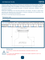
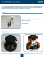
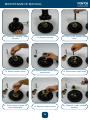
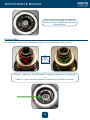
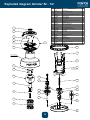
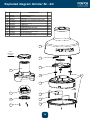
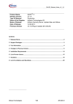
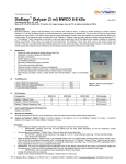
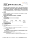
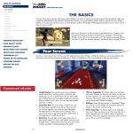
COMPLETE USER MANUAL
Grinder Winch 52
NO-013 (Ind A)
INDEX
INTRODUCTION3
Technical data
3
Dimension / Weight
3
Performances
4
INSTALLATION MANUAL
5
INSTALLATION PROCEDURE
6
USER MANUAL
7
MAINTENANCE MANUAL8
Tools
8
Disassembly
8
Cleaning
11
Reassembly
12
EXPLODED DIAGRAM 1/2 - GRINDER 52 13
EXPLODED DIAGRAM 2/2 - GRINDER 52
14
WARRANTY
15
2
INTRODUCTION
Pontos from Saint Malo in France has introduced a new standard to the world of winches. Our gamechanging winches revolutionize the way you manoeuvre. Our products are intended both for new boat
builders and for refitting. They are available on our website www.pontos.fr or in our approved retailers.
This technical manual gives important information on dimension, performance, installation, use and
maintenance of winches.
Thank you for respecting all the instructions presented in this textbook. The failure to respect these
instructions can expose the user to risks of injury or decrease considerably the life expectancy of the
winch and limit or cancel the product guarantee.
We invite you to read attentively this maintenance manual.
Technical data
Dimension / Weight
Working Load
DO NOT APPLY LOADS OVER INDICATED MWL, MAXIMUM WORKING LOAD.
Rope
IT IS HIGHLY RECOMMENDED TO FOLLOW OUR ROPES DIAMETER CHART ON
THE PREVIOUS PAGE.
3
INTRODUCTION
Performances
4
INSTALLATION MANUAL
GBR - INSTALLATION MANUAL
GRINDER AND TRIMMER INSTALLATION
Your winch must be installed on a flat part of the deck suitable to receive the winch. This area must be able
to support twice the announced maximum working load of the winch. It is the responsibility of the customer to
ensure the strength of the support and provide reinforcement if necessary.
Please follow carefully the installation instructions. Fitting bolts are not supplied by PONTOS. Only A4 stainless
steel bolts of the diameter indicated on the mounting template should be used.
10°
5°
1
2'
•
Place the template on the deck in such a way that the the output
gear is positioned where the sheet enters the drum. This ensures
the optimal performance of the winch. Carefully mark the bolt holes.
•
Arrow machined in the base shows the output pinion position.
•
Warning : Failure to correctly align the output gear can lead to
winch failure.
•
Output gear must be on the “line in” side.
•
Self-tailing feeder arm will be orientated in a position allowing free
stowage of extra line.
1. Unscrew the top ring.
2
2. Remove the top self. (either in 1 or 2 pieces depending on the version)
2''
3. Remove the drum.
3
4. Drill the holes in your deck.
4
5
5. Apply marine grade silicone sealant around the holes. Make sure
to keep draining holes clear.
•
Present bolts and tight up nuts progressively
•
Remove extra sealant
5
www.pontos.fr
NO-020 (Ind A)
INSTALLATION PROCEDURE
TM-5200 - Template Winch WMARC Size 52
REVISION "B" - DATE : 20/01/2015
THE WIND OF CHANGE
220
Ø extérieur
du winch
Winch external
diameter
Tambour
Drum
70
°
64 °
6 4°
Vérifier l'échelle de l'impression avant utilisation.
Check the scale of print before use this template.
°
6''
160 mm
70
46°
46°
150
(6x)
8,5
202
Vis : M8 Tête fraisée
inox A4 (DIN 267 part 11)
exclusivement.
Screws : use only M8 countersunk head,
A4 stainless steel (DIN 267 part 11).
Ø extérieur de la base
Base external diameter
: Fixer le winch pour que le pignon d'entrainement soit placé à l'endroit où le cordage entre
sur le winch. Utilisez la flèche sur l'embase pour vérifier l'orientation.
Un positionnement incorrect peut réduire la performance et la durée de vie du winch.
: The winch must be mounted in such a way that the drive gear is positioned where the
sheet enters the winch drum. Position the arrow perpendicular to the sheet.
An Incorrect mounting can reduce the performance and the life of the winch.
6
OPERATION MANUAL
GBR - OPERATION MANUAL
GRINDER - Ultra-Fast Winch-in
GRINDER winches from Pontos are designed to optimise the manipulation of halyards, sheets and
most lines used on a sailing boat. They will enable all crew members to hoist and trim much faster,
more easily and more safely in a comfortable and intuitive way.
In order to select the appropriate winch size, please refer to our website chart on www.pontos.fr
Warning: Reverse rotation for model 40
Gear 1 : 6 x first speed of a conventional winch
P
Gear 2 : 2 x first speed of a conventional winch
Or
O
N
T
Automatic clutch, PONTOS patented:
As soon as load is detected, 3rd gear is set-up.
O
> Carry on with gear 2
> Reverse the handle and engage gear 3
4
S
2 S
Gear 3 : = first speed of a conventional winch
S P
P E
E E
E D
Gear 4 : = second speed of a conventional winch
D
SELF-TAILING
Always make 3 turns on the drum or more if necessary. Engage the line on the
feeder arm and insert in the jaws about 300° around the winch.
EASING
A) Easing while keeping some load on the line maintains your winch in speed 3-4
B) Easing completely the line will bring you back to speed 1-2
NEVER APPLY LOADS OVER THE MAXIMUM VALUES GIVEN IN
OUR PERFORMANCE SPECIFICATIONS.
PONTOS WINCHES MUST NOT BE USED TO LIFT A PERSON.
7
www.pontos.fr
MAINTENANCE MANUAL
Your winch must be maintained and cleaned once a year. We recommend that you rinse your winch with
fresh water regularly in order to eliminate salt deposits. Failure to comply with these recommendations
could lead to damage to your winch and the cancelation of your warranty.
Tools
The tools required to dismount your winch are as follow:
- Marine Oil and Grease,
- 2.5 mm and 5mm Allen Key,
- A flat screw driver.
Disassembly
8
MAINTENANCE MANUAL
1. Unscrew the top screw
2. Remove the top self
3. Extract the drum by lifting
4. Remove the thrust
washer (if visible, depending
on the version)
5. Unscrew the stem top
6. Remove the stem stop
8. Remove the planetary shaft
9. Remove the white needle
roller bearings
7.
Remove the
Module
Grinder
9
MAINTENANCE MANUAL
10. Unscrew housing from
the base
11. Remove housing
12. Pull up the central main
shaft
13. Extract reverse pinion
14. Extract central pinion and
pawl carrier
15. Remove the output shaft
16. Push output pinions to
main central part
17. Remove output pinions
18. Remove lower needles
bearing
10
MAINTENANCE MANUAL
Cleaning
1. Clean and lubricate pawls
and springs
2. Verify the spring position before assembling the pawl.
3. Clean all pinions and shafts.
Add marine grease with
moderation. Excess Grease
will retain salt.
4. Rinse thoroughly the needle
bearings with fresh water.
Never grease them !
11
MAINTENANCE MANUAL
Rinse generously inside the drum at
least twice a year. Degrease and regrease
the crown gear.
Reassembly
To reassemble follow all of the disassembly steps in the reverse order. (Step 18 to 1).
Version 1 : Make sure the thrust washer is properly centered on the stem top.
or
Version 2 : Ensure the thrust washer is clipped into the head of the drum.
12
Exploded diagram Grinder 52 - 1/2
GRINDER 52 NOMENCLATURE - Folio 1/2
Rep REFERENCE
1
2
3
4
5
6
7
8
9
10
11
12
13
14
15
16
17
18
19
20
21
22
23
24
25
26
27
28
K1002
PM-5204-2
K5201
SM-0026
PM-0032
PP-5202
PP-5201
K1003
SM-0017
K1004
K1005
PM-0020
AE6475
PP-0012
AE-5203
SM-0024
PP-0002
PM-5208
PM-5220
PM-5210
K1001
PM-5230
K5204
PM-5213
PM-5203
PM-5212
AE-5204
K5205
DESCRIPTION
Qte
Top Screw
Top cap GRINDER 52
Self tailing kit 46-52
Screw CHC Low head M5x12 DIN 7984
Top self spring
Upper self jaw
Lower self jaw
Thrust Washer
Screw CHC Low head M4x10 DIN 7984
Stem top
Grinder module
Planetary shaft R Z15
Top needle bearing
Bearing spacer
Lower needle bearing
Housing Screw CHC M8X40
Crown ring
Main shaft
Pinion Z20
output pinion Z11
Pawl and spring kit
Pinion Z30
Pinion Kit
52 Stop washer
Out put gear pin
Pinion Z12
Output Needle bearing
BASE 52
Winch Grinder 52
même visuel pour Grinder 46
1
2
4
5
3
6
1
1
1
4
4
1
1
1
10
1
1
1
2
1
1
5
1
1
1
1
1
1
1
1
1
1
2
1
GRINDER 52 NOMENCLATURE - Folio 2/2
Rep REFERENCE
7
40
41
42
43
44
45
46
47
48
49
50
51
52
Sub-assembly
see next page
K5206
AE-0001
K1007
SM-0017
PM-5206
PM-0041
PP-0013
PP-0014
SM-0022
K5208
PM-5214
PP-5203
PP-5204
DESCRIPTION 15
GRINDER Support 52
Clutch assembly
Stop Ring
Screw CHC Low head M4x10 DIN 7984
16
Drum 52
Trigger ring spring
Trigger ring
Trigger Block
Screw CBL M3x8 UNI 7687
CROWN 52
52-46 Medium grinder spring
17
52-46 Friction pad
52-46 Drum washer cover
Qte
1
1
1
10
1
3
1
3
10
1
2
4
1
8
23
9
Sub-assembly
see page 2/2
C:\Users\xavier\Documents\Travail\01 ACCESSOIRES - KIT\Elements de travail\CAO BOM + éclaté Notice\NOMENCLATURE POUR KIT
10
27
18
20
11
19
12
13
21
22
24
23
25
26
14
28
13
23
24
25
26
27
28
K5204
PM-5213
PM-5203
PM-5212
AE-5204
K5205
Pinion Kit
52 Stop washer
Out put gear pin
Pinion Z12
Output Needle bearing
BASE 52
1
1
1
1
2
1
Exploded diagram Grinder 52 - 2/2
Même visuel pour
GRINDER 46
REFERENCE
DESCRIPTION
Qte
CHASSIS sub-assembly
DRUM sub-assembly
K5206
GRINDER
Support
52
1
Sous ensemble BÂTI
Sous ensemble POUPEE
AE-0001
Clutch assembly
1
GRINDER
52
GRINDER 52
K1007
Stop Ring
1
GRINDER 52 NOMENCLATURE - Folio 2/2
Rep
40
41
42
43
44
45
46
47
48
49
50
51
52
SM-0017
PM-5206
PM-0041
PP-0013
PP-0014
SM-0022
K5208
PM-5214
PP-5203
PP-5204
Screw CHC Low head M4x10 DIN 7984
Drum 52
Trigger ring spring
Trigger ring
Trigger Block
Screw CBL M3x8 UNI 7687
CROWN 52
52-46 Medium grinder spring
52-46 Friction pad
52-46 Drum washer cover
10
1
3
1
3
10
1
2
4
1
C:\Users\xavier\Documents\Travail\01 ACCESSOIRES - KIT\Elements de travail\CAO BOM
44 + éclaté Notice\NOMENCLATURE POUR KIT WINCH.xlsx
25/02/2015
See
previous
page
45
46
40
47
48
49
41
42
43
50
51
52
14
Warranty
Thank you for purchasing our PONTOS products. The warranty covers defects in materials and manufacturing of
the Pontos products during the warranty period as defined below.
It is intended for the original purchaser of the product upon presentation of proof of purchase. The Pontos range of
products is guaranteed for 5 years from the date of purchase.
To validate this warranty, please visit our website: www.pontos.fr and fill out the warranty form on the Customer’s
page. After the end of the warranty period, Pontos will not accept responsability for any other form of guarantee
either implicit or explicit for either private or commercial use. Depending on the country, other guarantees may exist
depending on the applicable law, the provisions of this warranty are not intended to counter these imperatives.
Application of warranty Procedure for warranty registration.
The warranty is applicable for the duration of its validity from the date of purchase.
I have a defective product ? What should I do ?
You will first need to define the problem by completing a «Product Return Form» available under customers profile
of our site www.pontos.fr. On receipt of the completed Product Return Form, Pontos will analyse the defect and
make a diagnosis. If the defect has not been caused by incorrect use of the winch then Pontos will decide to either
replace, repair or establish a credit note on the defective products reported. The shipping costs to return products
are not supported by Pontos. This warranty does not cover the costs associated with the diagnosis of an outside
professional, port fees or reinstallation of the product.
The Warranty does not cover, and Pontos cannot be held responsible :
• If the product is degraded during a return process (e.g inadequate protection)
• If the product has been modified with unauthorized spare parts
• If the product’s serial number has been removed, defaced or altered
• If the product has been subject to improper installation as per Pontos recommendations
• If the product has not been properly maintained as specified in the maintenance manual
• If the product has been used beyond its capacities or in an inappropriate way
• Used for a purpose other than for a maritime use for which the product was designed.
• If unauthorized modifications or repairs have been made
• For normal wear expected to be found during normal use of a winch
Responsibility
Pontos will not be responsible for:
• any loss of revenue expected, profits or indirect economic or consequential loss
• damages, costs or expenses payable to any third party
• damage to yachts or Equipment
• death or personal injury (unless they have been caused by the negligence of Pontos)
15