1
5K/10K Servo
Creep Controller
Instruction Manual
Interactive Instruments, Inc.
Corporations Park Bldg. 704
Scotia, N.Y. 12302
Interactive Instruments 5K-10K Servo Creep Controller
Information in this document is subject to change without notice and does not represent a commitment on
the part of Interactive Instruments, Inc. The software described in this document is furnished under license
agreement or non-disclosure agreement. The software may be used or copied only in accordance with the
terms of the agreement. It is against the law to copy the software on any medium except as specifically
allowed in the license or non-disclosure agreement. No part of this manual may be reproduced or
transmitted in any form or by any means, electronic or mechanical, including photocopying and recording,
for any purpose without the express written permission of Interactive Instruments, Inc.
2015 Interactive Instruments, Inc. All rights reserved.
Printed in the United States of America.
Companies, names, and dates used in examples herein are fictitious, unless otherwise noted.
Printed: October 20, 2015
2
Interactive Instruments 5K-10K Servo Creep Controller
Table of Contents
Introduction ................................................................................................................................................6
Safety Information ......................................................................................................................................6
Important Servo Maintenance Requirement ...............................................................................................6
Bearing Grease ...........................................................................................................................................6
Installation and Setup .................................................................................................................................7
Servo System Power Requirements ............................................................................................................10
Types of UPS systems ..................................................................................................................10
Power up ......................................................................................................................................11
Actuator Initialization...................................................................................................................11
Servo Controller Overview .........................................................................................................................12
Actuator Controller ......................................................................................................................12
Waveform Generator ....................................................................................................................13
Envelope Control ...........................................................................................................13
External Waveform Generator .......................................................................................13
Programmable Waveform Generator .............................................................................14
Programmable Waveform File Format
15
Data Acquisition ...........................................................................................................................16
Guide to the Servo Controller .....................................................................................................................17
Before starting a test .....................................................................................................................17
Resetting the Controller................................................................................................................17
LCD Menu options .......................................................................................................................17
Mode Control ...............................................................................................................................19
Immediate ......................................................................................................................19
Go To .............................................................................................................................19
Setpoint ........................................................................................................................................19
Waveform.....................................................................................................................................20
Constant Amplitude Control ..........................................................................................20
Cyclic Waveforms..........................................................................................................21
Waveform Envelope Start Control .................................................................................21
Waveform Envelope Reset Control................................................................................21
Ramping Waveforms .....................................................................................................22
Waveform Type .............................................................................................................24
Start ................................................................................................................................25
Hold ...............................................................................................................................25
Finish .............................................................................................................................25
Reset to Setpt .................................................................................................................25
Stop ................................................................................................................................25
Constant Amp ................................................................................................................25
View Max/Min .............................................................................................................................26
Peak Detector .................................................................................................................26
View Control ................................................................................................................................26
View Servo Stat. ...........................................................................................................................27
Setup.............................................................................................................................................28
View Setup .....................................................................................................................28
Setup Channels...............................................................................................................28
Reset Limit Trip Condition
29
Reset Control Loop Trip Condition
32
Actuator Rate .................................................................................................................35
Zero Channel ..................................................................................................................35
PID Parameters ..............................................................................................................36
Servo Parameters ...........................................................................................................37
Select Baud Rate ............................................................................................................37
Home Actuator ...............................................................................................................38
Reset Sys Stroke.............................................................................................................38
3
Interactive Instruments 5K-10K Servo Creep Controller
Setpoint Slew .................................................................................................................38
Network Config. ...........................................................................................................................39
View Config ...................................................................................................................39
Type ...............................................................................................................................39
IP, Subnet Mask, Gateway .............................................................................................39
About ............................................................................................................................................39
System Menu ................................................................................................................................40
USB Update ...................................................................................................................40
Lock Keypad ..................................................................................................................40
Recall Config. ................................................................................................................40
Store Config. ..................................................................................................................41
Reset Config...................................................................................................................41
Reset Servo Err. .............................................................................................................41
Restart Control ...............................................................................................................41
Reboot ............................................................................................................................41
View Status ....................................................................................................................41
Lock Remote Key ..........................................................................................................42
Feedback Display .........................................................................................................................43
Feedback Display Keypad ............................................................................................................44
Network Interface .........................................................................................................................45
WEB Server ...................................................................................................................45
Network Access .............................................................................................................46
ServoUpdate Windows Application ...............................................................................47
Identifying Servo Controllers
47
Network Configuration
47
Firmware Update
47
ServoRemote Windows Application ..............................................................................48
iPhone® Application......................................................................................................49
Block Diagram .............................................................................................................................49
Analog Port Connection ...............................................................................................................51
Shunt Cal........................................................................................................................53
Analog Output ..............................................................................................................................54
Servo Enable ................................................................................................................................55
Calibration ..................................................................................................................................................56
Load cell calibration .....................................................................................................................56
Auxiliary Calibration ....................................................................................................................56
Remote Commands .....................................................................................................................................57
Sending Commands ......................................................................................................................60
Set Servo Parameter (+S#,#) ..........................................................................................60
Read Servo Parameter (+s#) ..........................................................................................60
Set the programmable waveform (+P#,#) ......................................................................60
Read the programmable waveform (+p).........................................................................60
Set Acquisition Rate (AC#) ...........................................................................................60
Read Acquisition Rate (Ac) ...........................................................................................60
Sample one data sample set (AA) ..................................................................................60
Read Acquired Data (Ar#) .............................................................................................61
Stop Data Acquisition (AS) ...........................................................................................61
Clear Acquisition Memory (AR) ....................................................................................61
Start Data Acquisition Timer (AM) ...............................................................................61
Reset acquire index to 0 (AN) ........................................................................................61
Read acquire index (An) ................................................................................................61
Set the 3 acquired channel numbers (AD#,#,#) ..............................................................61
Read the 3 acquired channel numbers (Ad) ...................................................................61
Read Servo Status (.)......................................................................................................61
Read data (a) ..................................................................................................................61
Read Maximum Loop Control Error (b#) ......................................................................61
4
Interactive Instruments 5K-10K Servo Creep Controller
Set Maximum Loop Control Error (B#,#) ......................................................................61
Enter Remote Control (C#) ............................................................................................62
Read waveform output value (d) ....................................................................................62
Set waveform output value (D#) ....................................................................................62
Read Units (e#) ..............................................................................................................62
Set Units (E#,#)..............................................................................................................62
Read Setpoint (f) ............................................................................................................62
Set Setpoint (F#) ............................................................................................................62
Read Channel Ranges (g#) .............................................................................................63
Set Channel Ranges (G#,#) ............................................................................................63
Reset Total Max/Min's (H) ............................................................................................63
Read Max/Min's (h#) .....................................................................................................63
Read PID Parameters (i#) ..............................................................................................63
Set PID Parameters (I#,#,#,#) ........................................................................................63
Read system or channel value (j#) .................................................................................63
Write system and channel value (J#) ..............................................................................67
Read Max limit (k#) .......................................................................................................69
Set Max limit (K#,#) ......................................................................................................69
Read Min limit (l#) ........................................................................................................69
Set Min limit (L#,#) .......................................................................................................69
Read LCD data (m) ........................................................................................................69
Send Keypad character (M#) .........................................................................................69
Read port filter factors (n#) ............................................................................................69
Set port filter factors (N#,#) ...........................................................................................69
Read Control Channel (o) ..............................................................................................69
Set Control Channel (O#) ..............................................................................................69
Set Waveform Parameters (P#,#,#,#,#,#,#) ....................................................................70
Read Waveform Parameters (p#) ...................................................................................70
Set Waveform State (Q#) ...............................................................................................71
Read Actuator State (q) ..................................................................................................71
Set Limit Action (R#,#,#)...............................................................................................71
Read Limit Action (r#,#) ................................................................................................71
Read actuator rate (s) .....................................................................................................72
Set actuator rate (S#) ......................................................................................................72
Reset Waveform timer (T ) ............................................................................................72
Read Waveform timer (t) ...............................................................................................72
Read Controller status (u) ..............................................................................................72
Reset all action alarm flags (V#) ....................................................................................72
Firmware Version (v) .....................................................................................................73
Read waveform pause status (w) ....................................................................................73
Set waveform pause status (W#) ....................................................................................73
Restart Firmware (X#) ...................................................................................................73
Read cycle count (y) ......................................................................................................73
Read Channel Offsets (z#) .............................................................................................73
Set Channel Offsets (Z#,#) .............................................................................................73
Help (?) ..........................................................................................................................73
Error Conditions ...........................................................................................................................74
Servo Specification .....................................................................................................................................75
Troubleshooting..........................................................................................................................................76
Limited Warranty .......................................................................................................................................77
5
Interactive Instruments 5K-10K Servo Creep Controller
Introduction
The 5K-10K Servo Creep Controller is capable of continuous or cyclic loads up to 5,000 or 10,000
lbs depending on the servo load frame. The unit is capable of maintaining constant load conditions
for days, months and even years with minimal maintenance requirements. The Servo system is
also capable of sustained cyclic motion as well. Cyclic motion is programmable from as low as 10 300
Hz up to 10 Hz and beyond (under limited test conditions). The higher the test frequency runs
the shorter the actuator stroke due to the servos limited actuator rate. Optimal cyclic control rate is
typically less than 5 Hz.
Safety Information
The Servo is capable automatically moving the actuator with very high forces, very quickly.
It is important to observe and follow all safety information in this manual. While working
on the servo load frame is important to disable the servo controller by powering down the
system and prevent other operators from intentionally or unintentionally powering up the
system while someone is working on or around the load frame.
Remember, even of the load is programmed to control a low force, the actuator is still
capable of forces in excess of 10,000 lbs. so safety must be exercised at all times especially
while working on or around the load frame.
Important Servo Maintenance Requirement
Note: A limitation of the Servo system is that when operating cyclic loads over 300,000
cycles the bearings need to be maintained on a regular bases. When the actuator approaches
300,000 cycles it is very important to remove the system load and cycle the actuator over the
entire 3.25" stroke range for several cycles to redistribute the grease. It is also important to
lubricate the system with the recommended grease as well. The main bearing is not covered
under the limited warranty agreement and would require the load frame be sent to
Interactive Instruments for repair.
Bearing Grease
The main thrust bearing must be lubricated periodically or the bearing will fail. Attach a
standard grease gun loaded with the recommended grease (see below) to the fitting on the
motor thrust plate above the motor. It is recommended to lubricate the bearing every half
million to a million cycles by squeezing the grease gun handle 10 times. Once the grease is
injected it should be redistributed by moving the actuator over the full range of stroke.
The grease is a special lithium grease called "Lithium Complex EP Grease" and it can be
purchased from Dieco (www.dieco.us).
The actuator ball screw can be inspected by pulling down the bellows near the load cell to
expose the screw assembly. Add the same lithium bearing grease to the ball screw to keep it
lubricated and re-attach the bellows to keep dirt and debris from contaminating the screw.
6
Interactive Instruments 5K-10K Servo Creep Controller
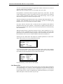
Installation and Setup
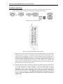
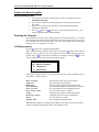
On the bottom of the Servo controller panel you will find several connectors as shown below.
Follow the steps below to prepare the system before powering up the load frame.
Bottom of Servo Controller Panel
Rear of Copley Xenus Plus XPL-230 Servo Drive
1) Mount the servo drive panel (with the red/yellow power switch) and the servo control panel
(with keypad) into a 19" rack. It is preferable for the servo drive to be mounted close to the
bottom of the rack keeping the servo drive as cool as possible so heat from panels below it
don't increase the ambient heat of the drive. The two servo motor cables will also have to
reach the load frame so placing the panel close to the ground is usually the best position. The
servo control panel should be placed at or below eye level to make it easy to read the LCD
and press the keys on the keypad. The interconnecting cables are only 6 foot long so be sure
the controller is close to the servo drive panel.
2) Install the load frame firmly to a stationary platform. The actuator is capable of rapid motion
so be sure the load frame is securely mounted before operating. Check to make sure the two
servo motor connectors are easily accessible. If the servo load frame is mounted
horizontally, be sure to support the weight of the load frame. The top mounting ring has 3
mounting holes that are 0.531" equally spaced on a 7.5" diameter bolt circle. The load cell
has a 1-14 UNS thread interface. Note: When threading into the load cell, be sure to stop
at least ¼ inch before hitting the bottom to prevent interference between the load cell
and the frame.
7
Interactive Instruments 5K-10K Servo Creep Controller
3) Plug the 26 pin high density controller cable connector into the bottom of servo control panel
labeled SERVO and plug the other end into the mating connectors located on the Copley
servo drive (J8). The 26 pin cable is used to exchange high speed digital position commands
between the servo controller and drive. Secure the ends of the cable with shell screws.
4) Plug a standard 9 pin cable into the Copley servo drive port J5 and the other end into the
male 9 pin port on the servo controller panel labeled “SERVO SAFETY”. This cable is used
to supply power to the servo driver as well as enable the driver. Secure the ends of the cable
with shell screws. DO NOT PLUG THE SAFETY CABLE INTO THE SERVO
COMMUNICATIONS PORT (also a DB9) OR THE SERVO DRIVER WILL BE
DAMAGED.
5) Plug a standard 9 pin cable into the Copley servo drive panel (Right side of driver) and the
other end into the matching port on the bottom of the servo controller panel labeled SERVO
COM. This cable is used to communicate serially between the servo controller and drive.
Secure the ends of the cable with shell screws. Be sure not to mistake the servo com cable
for the safety cable (both DB9) as noted in the previous step.
6) In some installations it is helpful to install a grounding wire between the servo drive and the
servo motor to reduce load feedback noise. Attach a stranded wire or a grounding strap
between the screw at the back of the servo drive panel to one of the screws on the servo
motor case can lower the analog load cell noise.
7) NOTE: The servo drive may not operate properly if the cables are not fully seated and
secured.
8) If a network is available, it is advised to plug a RJ45 Ethernet cable between the servo
controller port (bottom of controller panel) and your local network switch or hub. The
network can be used to monitor the servo system and can be used to update the system
firmware. The servo controller can operate without the use of a local network.
9) Plug the servo motor feedback cable (high density DB26) into the rear of the servo driver
port labeled “J10” and secure the connector with the two screws. Plug the other end of the
cable into the round mating connector (with narrow pins) on the servo motor. This cable
sends the rotational position feedback to the servo driver and to the servo controller. You
should not use any tools to tighten the connectors, only tighten by hand. Align the connector
before tightening the connector housing. Rotate the connector until it aligns with the motors
mating connector. Once the connector aligns, it will drop in and begin to make contact.
Thread the connector barrel until the connection is snug, securing it into place. As the barrel
is tightened, be sure to press in on the connector until it can't be pressed further and the barrel
is snug. The connector has an O ring seal to keep the connection clean so you will feel some
resistance before the connection is fully seated. Note: If the cable comes loose while the
system is operating, the system will produce unpredictable motion and possibly shut down
so it is important that the cable is properly secured.
10) Plug the round servo motor power cable from the rear of the servo drive panel into the
mating connector (with thick pins) on the servo motor. It's important that the connector is
fully seated or the system will not operate properly. You should not use any tools to tighten
the connectors, only tighten by hand. Align the connector before tightening the connector
housing. Rotate the connector until it aligns with the motors mating connector. Once the
connectors align, they will drop in and begin to make contact. Thread the connector barrel
until the connection is snug, securing it into place. As the barrel is tightened, be sure to press
in on the connector until it can't be pressed further and the barrel is tight. The connector has
an O ring seal to keep the connection clean so you will feel resistance before the connection
is fully seated.
8
Interactive Instruments 5K-10K Servo Creep Controller
11) Connect the round end of the load cell cable into the load cell and rotate it until it is seated.
Then rotate the outer connector barrel to lock it in place. Connect the other end of the load
cell cable into the load cell port (Port A) on the bottom of the servo control panel. Be sure
to secure the cable to the control panel using the two screws on the connector shell. The Cal
button (recessed) can be pressed to verify the calibration of the load cell attached to port A.
See Port connection for more information about using shunt cal.
12) Plug the power cord socket attached to the servo drive panel into the rear of the servo control
panel. The Servo controller gets its power from the servo drive panel so only one power
cord is needed for the system
13) Attach the main power cord plug into a 110 volt (or 220V if designated) grounded wall
outlet. Avoid GFI (ground fault interrupt) protected outlets because the servos electrical
noise on the ground line may falsely trip the breaker.
9
Interactive Instruments 5K-10K Servo Creep Controller
14) Inspect the load frame, control panel, servo drive panel and cables for shipping damage. If
any damage was caused in shipping, please contact Interactive Instruments immediately.
Operating a damaged unit may result in additional damage or personal injury.
15) Check all of the cables to make sure they are properly connected and secured. Verify the
servo driver com and safety cables go to the proper connectors to prevent damage to the
driver.
16) Check that the servo drive is enabled. The enable button on the front servo control panel
should be pushed in or the drive will not operate. Any time someone works on the near the
load frame while under power be sure to disable the servo drive to prevent unexpected
motion.
17) Verify the actuator is free of obstruction before applying power.
18) Power up the unit by rotating the Main Switch on the servo driver panel to the On position.
The controllers operating system will require about 12 seconds to boot up, in that time the
LCD will display 2 black bars.
19) As the unit is booting up, the controller will access the DHCP server if available and
automatically use the assigned network address. If a DHCP server is not available, a static
address can be assigned.
20) Note: After powering down the controller, be sure to wait 5 to 10 seconds before applying
power again. If the load feedback appears incorrect, turn off the controller power, wait 10
seconds and restore power.
Servo System Power Requirements
The servo controller and load frame doesn’t require a lot of power to operate. Below is a table
of approximate required power for a 110 volt 60 Hz system. As you can see a relatively small
uninterruptible power supply (UPS) could relatively easily supply power to one or more units,
maintaining a controllable load throughout a power outage.
10K Load Frame
Load
Power
0 lbs
35 watt
1000 lbs
50 watt
2000 lbs
65 watt
3000 lbs
80 watt
4000 lbs
110 watt
5000 lbs
130 watt
6000 lbs
180 watt
7000 lbs
210 watt
8000 lbs
260 watt
9000 lbs
330 watt
10,000 lbs
400 watt
Types of UPS systems
There are generally two types of UPS units, online and offline. The less expensive offline UPS
will work but some power line disturbances pass through to the UPS disrupting the controller.
More expensive Online UPS is a better choice for critical applications when you can’t afford to
lose load control.
10
Interactive Instruments 5K-10K Servo Creep Controller
Power up
If the controller diagnostics pass all internal tests, the LCD will then prompt:
Power Up OK
Initialize Actuator?
Press 1 to Home
or 0 to Stay
Press the 1 key on the front of the control panel to locate the home switch or press 0 to maintain
the same actuator position. Since the actuator position is stored in memory, the actual position
may be different than the stored position if the actuator moves while powered down.
Note: Before the actuator moves to locate the home position be sure the test are is free of test
specimens or the specimen may be damaged.
Actuator Initialization
Pressing 1 displays a confirmation prompt below. Pressing 1 a second time and the actuator moves
down to locate the bottom position. This is done by slowly moving the actuator and waiting for
the servo motor to stop at the bottom most position. Once the actuator stops moving it assumes it
is the lowest possible position. If an object blocks the actuator from moving, the home position
may be incorrect and it is best to relocate the proper end position.
Ready to Home
Press 1 to Confirm
or 0 to Cancel
Note: It is preferred to locate the home location after power up but if a specimen is already
mounted then it is better to assume the current position. If the actual and stored position is off by
more than 1/4" the actuator can bottom out internally causing the servo to stall and release the
load.
While the controller is active or in control, the status LED on the control panel will blink to
indicate possible servo activity. The same LED will indicate an error condition by flashing at a
faster rate and will be on steady if the actuator is stopped.
Note: The servo controller will ignore serial and network commands until the controller is active
(LED blinks continuously). This is a safety feature to prevent automated programs from taking
control of the actuator so the operator is in complete control after power up.
11
Interactive Instruments 5K-10K Servo Creep Controller
Servo Controller Overview
The servo controller software is the front end program that contains the user interface to the
actuator control and the waveform generator. The actuator controls main job is to determine where
the actuator should be positioned to maintain minimal control error while monitoring various
system limits and conditions. The actuator is controlled by sending digital position commands to a
servo driver program which is responsible for controlling and monitoring the servo motor. As the
servo motor is repositioned, the servo motor feedback is returned to the servo driver as a digital
signal which updates the servo control program. The digital position command and feedback
allows for high speed positioning and reliable noise free response over a wide dynamic range.
Actuator Controller
One of the requirements of the actuator controller is to be able to precisely position the actuator
over a wide range of speeds. The servo controller sends a constant stream of pulses to the servo
drive to control the actuator position. A separate line is used to control the direction of the motion
so the actuator can be controlled up and down at a controlled rate. Each controller pulse sent to
the driver moves the actuator a fixed distance, the smaller the distance, the finer the control
motion. The servo driver is programmed to input 524,288 pulses for every inch of actuator travel
so the effective positioning resolution is 1.90735e-6 inches per pulse. The fine position resolution
allows for very precise load stroke and strain control.
A programmable timer is used to adjust the speed of the pulses to control the actuator between
very slow rates to the maximum allowed system actuator rate. Unlike a servo hydraulic system, the
servo electric system is able to control the maximum allowed actuator rate to suit test
requirements. Typical servo hydraulic systems are pre-configured for one rate only, fast or slow.
The servo controllers maximum actuator rate is a programmable limit that prevents the actuator
from operating too fast. Some tests such as high cycle fatigue test require very fast rates where
control accuracy isn’t as much an issue. Long term creep strain tests sometimes require very slow
actuator rates for smoother control and improved control accuracy. The servo controller is able to
fill both requirements with the same piece of equipment. The typical actuator rate is set to a value
that would be acceptable for most test conditions or about 20 inches per minute for moderate
control response. The waveform generator is then used to control the actuator load, stroke or
strain control. The control error is calculated and the actuator rate is adjusted up to the maximum
actuator rate to reduce the control error back to near zero. Some test such as long term creep tests
require precise control, so a slower actuator rate is used instead of the typical 20 inch per minute
rate. As the waveform adjusts the control point, the actuator ramp is clamped to prevent rapid
actuator motion from disrupting the sensitive test environment. Actuator rates as low as 0.00001
in/min are possible for the finest actuator control so actuator adjustment will be dampened
significantly. Select an actuator rate that would be fast enough to maintain minimal control error.
A good rule is to use a rate at least twice the required rate, to make sure the actuator can move fast
enough to minimize control error. Some experimentation may be necessary for load control
applications to determine an acceptable actuator rate.
High cycle fatigue may require a faster rate than 20 in/min. Setting the actuator rate to 75 in/min
will greatly improve the cyclic frequency response at the expense of control accuracy. The higher
rates will permit speeds approaching servo hydraulic testers at a fraction of the system and
maintenance cost.
Note: Care must be taken when operating the load frame at high cyclic rates for long periods of
time. See the section Important Servo Maintenance Requirements above.
12
Interactive Instruments 5K-10K Servo Creep Controller
Waveform Generator
The waveform generator can be programmed to manipulate the control point over a wide range of
frequencies and amplitudes. The waveform generator is capable of controlling the current control
channels, load, stroke or strain. The generator is capable of generating cyclic frequencies as low
as 10-300 Hz on up to 30 Hz. It is also capable of controlling ramps from 10 -300 units/minute up to
10+300 units/minute (units are load, stroke or strain depending on the control channel). Although
the waveform generator is capable of 30 Hz, it is unlikely it will be able to reliably support that
rate. The waveform generator output is updated up to 1000 times a second and the waveform
output is added to the current setpoint to generate the new control point which the controller will
attempt to control. The waveform generator is open loop so it can’t guarantee the control error
will be near zero, that is up to the test conditions and the controller settings. The actuator rate
should be adjusted in conjunction with the waveform generator and control accuracy requirements.
Faster cyclic tests and ramps will require fast actuator rates while slower waveforms may require
slow actuator rates. As the waveform generator updates the control point, the actuator controller
will attempt minimize the error by moving the actuator rate slowly (for small errors) up to the
maximum actuator rate (for large errors). This is why it may be important to consider the actuator
rate for every test condition.
Envelope Control
The waveform generator has the ability to slowly increase and decrease the waveform amplitude
over a period of time. Controlling the start and reset time is useful when applying high amplitude
or high frequency waveforms. Start and reset times can be programmed form 0.001 to 100.000
seconds for each of the three independent waveform generators. The envelope control is only
available for cyclic bipolar and unipolar waveforms such as sine, haversine etc.
Envelope Waveform Control
External Waveform Generator
An external waveform can be used to control the load or stroke channel using an analog control
signal. The analog signal can be scaled to a desired range to best represent the analog control
signal. The control signal is received on the AUX channel analog input and scaled internally and
added to the load or stroke channel. For example you can program the controller to create a 0 to
2000 lb. waveform with a 0 to 10 volt signal. The analog voltage will modify the setpoint
depending on the voltage on the AUX port. This is useful if the test waveform can’t be duplicated
with the internal waveform generator.
13
Interactive Instruments 5K-10K Servo Creep Controller
Programmable Waveform Generator
Custom waveforms can be downloaded into the controller to create a unique sequence of cyclic
ramp segments. Once loaded, the waveforms amplitude and frequency can be further adjusted by
the user interface for added flexibility. Waveforms are programmed by loading a list of amplitude
values and optional ramp segment times (one segment per line). From 1 to 1000 ramp segments
can be programmed to perform smooth sequential list of ramps to emulate virtually any waveform.
Using Excel or other spreadsheet programs, complex waveforms can be created and exported to a
text file rather easily. The structure of the waveform file is very simple and easy to create. Each
line represents a waveform segment and contains an amplitude value which is typically of the
range +1.0 to -1.0 but can be any value. The amplitude values are used to control the overall shape
of the waveform. Once a waveform is loaded, the controller automatically normalizes the
amplitude values so the waveforms true amplitude is controlled by the waveform generators
amplitude. The waveform amplitude value is multiplied by half the waveform generator amplitude
to create the waveform generator output for the specific control channel. A stored waveform can
be reused for stroke or load control since each channel can has a different waveform generator
amplitude. Once a waveform is downloaded, it is available for any control channel just by
selecting the programmable waveform.
Each waveform segment text line can also have an optional time value (in seconds) separated by a
comma. The time controls how long it would take to ramp from the previous segment value to the
current value. A time of 0.5 would generate a ramp that transitions to the new amplitude in 1/2
second while a value of 2.0 would perform the ramp in 2 seconds. The time value allows for long
constant hold times or fast ramp segments if needed. If the time entry is zero or not included on
the segment line, the duration is automatically set based on the current waveform frequency and
the number of segments in the file. For example, loading a 10 segment waveform with the
waveform frequency set to 0.125 hz will program each segment time to 0.8 seconds
(1.0/(0.125*10) = 0.8 sec) so the waveform cycles every 8 seconds. Simple waveforms can be
loaded by using a file of amplitude values (one entry per line) and the servo controller calculates
each segment time automatically. This way complex waveforms can be easily loaded by using a
simple list of amplitudes.
Waveforms are loaded using USB flash memory drives. The waveforms are stored in a text file
with the extension “.WAV” and are loaded into the controller when Programmable Wave is
choosen and the waveform file is selected. The waveform file should be saved to a USB flash
drive then plugged into one of the two USB connectors on the bottom of the servo controller.
Once a waveform file is loaded into the controller, the USB flash is no longer needed and can be
safely removed. Any further changes to the waveform are performed on the locally controller
copy.
Note: You can use a standard USB extension cable to extend the USB port to a more convenient
position.
Multiple waveforms can be stored on the USB device at one time, the waveform menu interface
will display a list of “.WAV” waveform entries for you to select between. When a waveform is
loaded which is found to have programmed segment times, the waveform frequency is
automatically set to accommodate the total of all segment times. This value can be overridden by
programming another frequency, the controller then scales each time entry to arrive at the to the
new frequency. Reloading the original waveform from a file will restore the time segments to the
original values and the original frequency.
14
Interactive Instruments 5K-10K Servo Creep Controller
Programmable Waveform File Format
The waveform file is an editable format that can be created using Notebook or any ASCII text
editor. The file name must end in “.WAV” and can have from 1 to 1000 line entries, one for each
ramp segment. Each segment should be terminated with a carriage return. The first line is special
and can contain a descriptive name of the waveform such as “LoadProfile-2” or “Log Sweep-2X”.
The optional waveform name will be automatically truncated to 20 characters to fit on the display.
The name should begin with a letter to prevent it from getting confused with a waveform value. If
the waveform name is not available, the USB file name will be used instead. The name is
displayed whenever the programmable waveform type is viewed.
The examples below represent two different types of waveforms. Example #1 is a 14 segment
bipolar waveform (both +/- values) with constant segment times. Since the amplitudes don’t have
time durations associated with the segments, the time is based on the waveforms cycle frequency.
Example #2 is a similar waveform but programmed unipolar (positive values only). Notice each
line has two values, the first being the amplitude and the second (separated by a comma) is the
time in seconds the generator takes to ramp to the value. Even though example #2 amplitude is
half of example #1, both waveforms will have the same amplitude since the values are normalized
internally. Example #3 shows how easy it is to create a simple triangle waveform. With up to
1000 entries, virtually any waveform can be customized.
Waveform Example #1
Custom Wave-1
0.1
0.9
1.0
1.0
0.9
0.1
0.0
-0.1
-0.9
-1.0
-1.0
-0.9
-1.0
0.0
Waveform Example #2
Custom Wave-2
0.1,1.0
0.9,2.0
1.0,1.0
1.0,0.5
0.9,1.0
0.1,2.0
0.0,1.0
0.0,0.5
Waveform Example #3
Triangle Wave
1.0
-1.0
15
Interactive Instruments 5K-10K Servo Creep Controller
Data Acquisition
The controller has an internal data acquisition feature that will allow you to sample up to 3 internal
system or channel parameters synchronously or asynchronously for up to 10,000 samples. The
data acquisition feature is only accessible with remote commands due to the amount of data
involved.
The default data channels sampled are load, stroke, AUX feedback values but any 3 channel or
system parameter can be programmed to be acquired.
Synchronous sampling is performed by programming the sample rate in samples per second. Once
set the sampling is performed automatically until the sampling is suspended or the acquisition
memory fills. Sampling rates can be programmed from as fast as 1000 samples per second to as
slow as 1e-300 samples per second.
Asynchronous sampling is performed by sending a sample command to the controller whenever
data is to be sampled.
Once the data is collected or even as data is being collected, the data samples can read from
memory. You can read from 1 to all 10,000 data sample sets using remote commands.
Note: At times the controller is too busy to acquire a data sample when sampling at rates over 200
samples per second. Missing data samples will be replaced by duplicating the following data
sample. The time stamp will reflect the missing entry by indicating duplicate time stamps.
16
Interactive Instruments 5K-10K Servo Creep Controller
Guide to the Servo Controller
Before starting a test
Verify that the load frame controller and servo drive are properly setup (see
Installation and Setup)
Power up the controller by switching the power switch located on the Servo
drive panel
Wait 10 to 15 seconds for the controller to boot up and begin displaying
information on the LCD
Press the
(enter) or
(menu) key to locate the home switch or stay. The
LCD will prompt with the feedback display.
Resetting the Controller
The controller stores some of the control parameters in nonvolatile memory. To reset all
control parameters (and actuator position) back to the factory default settings, power up
the controller with the 0 key held down. The LCD will prompt with a confirmation
message. Press 1 to confirm or 0 to cancel.
LCD Menu options
Press the
(menu) key to display the Main Menu.
Note: When entering a parameter value with the keypad the
button will first delete
characters one at a time if one or more digits have been entered and then cancel the
numeric entry if
is pressed after all characters are deleted. Pressing the
key will
also exit from the menus, and return to the feedback display.
Main Menu
1) Mode Control
2) Setpoint
3) Waveform
Pressing the UP/Down arrows on the keypad will move the pointer through the list of
menu options. The list includes:
Mode Control
Setpoint
Waveform
View Max/Min
View Control
View Servo Stat.
Setup
Network Config.
About
System Menu
(Select between load, stroke or aux control)
(Set the desired control setpoint)
(Configure and control the waveform generator)
(View the Max and Min feedback values in real time)
(View the actuator control, feedback and error)
(View the status of the servo motor)
(Configure the System and Channel parameters)
(Configure and view Network configuration)
(View the Software Version)
(System updates and management)
Note: While the display is not showing the feedback screen and a key isn’t pressed in 60
seconds, the display automatically returns to the feedback screen.
17
Interactive Instruments 5K-10K Servo Creep Controller
Mode Control is used to select which channel (load, stroke or auxiliary) is in control.
Two options are available when transferring control to another channel. Option 1 is to
automatically set the setpoint to the measured feedback of the selected control channel
(Immediate) or option 2 is to go to a programmed setpoint immediately after the transfer
is complete (Go To).
Setpoint is used to program the current setpoint value (or reference point) all
waveforms are applied to. If the waveform is not active, the actuator controls to the
programmed setpoint.
Waveform selects the waveform generator configuration and control options menu.
Configurations include selecting the waveform type such as sine, square, triangle,
haversine, haversquare, havertriangle, single ramp, dual ramp and trapezoid along with
the required parameters. An external waveform is also available using the AUX analog
input channel. The waveform control options are available to start, hold, finish, reset and
stop the waveform generator. Each control channel maintains separate set of waveform
parameters so the parameters don't require reprogramming if the mode control is changed
back and forth. Waveform commands are also preserved after power up.
View Max/Min View a channels maximum and minimum feedback values in real time.
The display will indicate the overall max and min values since the waveform was started
along with the max and min values for the previous waveform cycle. The values are
evaluated and updated appropriately. The feedback amplitude and mean value can be
monitored in real time as well using the down arrow. Pressing the up arrow will redisplay the max/mins.
View Control View the current control value (waveform + setpoint) along with the
control feedback value and the current control error. The bar graph on the top of the
display represents the relative control error.
View Servo Stat. View the Servos drive current, drive temperature, status and
load. These indicators are a good way of determining how hard the servo motor is
working and whether the servo is being overstressed.
Setup Display the setup menu for configuring the system and channel setup parameters.
Network Config. Displays a list of menu items to view and modify the current
network configuration. The network can be configured as a DHCP or Static network. If
your local network has a DHCP server, the controller can request a valid IP address for
your network. A static IP address can be selected if DHCP is not available or if a static
IP is desired. If the servo controller is not plugged into a local network, ignore this menu.
About Views the software version and copyright notice.
System Menu The controller firmware can be updated using a USB flash memory
stick. Other menu options are available to restart the control software or reboot the servo
controller.
18
Interactive Instruments 5K-10K Servo Creep Controller
Mode Control
The controller can be programmed to control load, stroke or auxiliary (analog sensor).
To change from the current control mode into a new control mode select the Mode
Control menu item. The display will prompt with a list of control channels. Select one of
the channels by entering 1, 2 or 3 to select Load, Stroke or Aux. The display then
prompts with options on how the control change will take place. For Aux control, be sure
an appropriate sensor is installed in the Aux analog port and is properly scaled and
calibrated.
Immediate
The first option (Immediate) will quickly transfer control to the new channel and set the
current setpoint to the control channel feedback value. As long as the new feedback
channel is stable the transition should have minimal effect on the actuator position.
Go To
The second option (Go To) allows a new setpoint to be programmed immediately after
the transfer of control is performed. This is an efficient method of switching control and
programming the new setpoint in one operation. For example, while in stroke control you
can switch to load control at 100 lbs. by selecting Go To 100 lbs.
Setpoint
Programs the setpoint to a new value. The setpoint is the mean value of the of the
maximum and minimum excursions of the controlling waveform. On normal cyclic
waveforms (sine, square, triangle) it is the center point which the waveform swings. On
haver waveforms it is the starting and end point.
All setpoint transitions are made as quickly as possible. The actual rate depends on the
selected actuator rate.
The default setpoint is the current setpoint. Pressing Enter (or menu) without entering a
new value re-selects the current setpoint.
The setpoint can be changed at any time even while a waveform is running.
Note: The setpoint can’t be changed if the actuator is stopped. Restart the actuator by
pressing and holding the ‘.’ key for a second while in the feedback display mode, then set
the new setpoint.
19
Interactive Instruments 5K-10K Servo Creep Controller
Waveform
Each control channel has a programmable waveform generator with separate parameters
providing a command signal to drive the servo system when that channel is in control.
Only one set of waveform parameters are enabled at a time allowing the load, stroke or
auxiliary to be controlled while monitoring the independent feedback channels.
The waveform parameters are saved in non-volatile storage for each channel, if the
controller is powered down, the parameters will be preserved so the same waveform can
resume by just selecting the menu option Start from the waveform menu.
Internal waveforms fall into three groups: bipolar waveforms comprising sine, triangle
and square, unipolar waveforms comprising haversine, havertriangle and haversquare, and
ramps which can be connected and repeated to form single ramps, dual ramps and
trapezoidal waveforms.
Note: See the Important Servo Maintenance Requirement section above for long term
high cycle testing.
Constant Amplitude Control
Constant amplitude control is available for trapezoid, sine, square, triangle and the haver
cycle and programmable waveforms. The constant amplitude controller option can be
enabled to greatly improves the actuators frequency response for multiple cycle testing.
This option can be turned on and off remotely or by the keypad. When enabled the
waveform generator monitors the previous cycle feedback peaks and the results control an
outer loop adjusting the waveform amplitude to continuously adapt to the desired
amplitude. The constant amplitude control also monitors the feedback mean value and
compares it to the desired mean and adjusts the setpoint to adapt to the desired mean for
each cycle. Neither of these controls modify the operators amplitude and setpoint values,
they are temporarily tweaked using internal variables. Constant amplitude control only
works for sine, square, triangle and haver and programmable waveforms which are
primarily used for fast cycle control, ramps are not impacted even when constant
amplitude is enabled. Enabling this feature allows the actuator frequency response to be
pushed much farther. Turning constant amplitude control off (and after power up), the
waveform generator returns to the original control.
Effort was made to adapt the waveform output closely to the waveform parameters. In
some cases the constant amplitude control can go outside the bounds of the parameters
but this was typically when the waveform parameters (amplitude, setpoint, wave type etc.)
are adjusted dramatically manually by the operator. In most cases, the constant amplitude
control does a very good job of matching the waveform parameters as long as they are
within the servos performance range.
Note: To minimize the constant amplitude control adjustment errors while significantly
modifying the waveform parameters, it may be better to temporarily disable the feature,
change the parameters and wait an appropriate amount of time to stabilize control, then
re-enable.
20
Interactive Instruments 5K-10K Servo Creep Controller
Cyclic Waveforms
Bipolar
Bipolar waveforms are cyclic waveforms that start at a setpoint, proceed to a peak
amplitude (positive or negative), reverse direction pass through the setpoint to the
opposite peak amplitude and then return to the setpoint. When selecting bipolar
waveforms, you must specify the set point, amplitude, frequency and the starting direction
(amplitude sign) of the waveform.
Unipolar
Unipolar waveforms have the same shape as bipolar waveforms but are offset by the
cyclic mean value form the setpoint. The cyclic mean is the mean level of the peak-topeak amplitude. This means that the waveform excursions take place entirely above or
below the setpoint. This feature is useful when you wish to start your test with a pre-load
on your specimen then have the specimen load cycling take place entirely above or below
that pre-load without unloading the specimen.
Note: When the waveform generator output is added to the current setpoint. The +/- sign
in the upper left corner of the feedback display signals that a waveform output is
modifying the current setpoint. When the sign is blank, the waveform output is zero, and
not impacting the setpoint.
Waveform Envelope Start Control
The startup can be controlled for cyclic waveforms to softly start a test. A programmable
timer can be set to quickly or slowly ramp the waveform amplitude up to maximum
amplitude. The timer can be adjusted from 1 ms. up to 100.000 seconds before reaching
full amplitude. Each of the three internal waveform generators can be programmed to
have different start ramp times. Pausing the waveform will suspend the start envelope
timer as well but restarting the waveform will restart the envelope timer to zero but start
at the current amplitude. If the amplitude of the waveform is modified, the internal
envelope start cycle will automatically reset to slowly increase or decrease to the new
waveform amplitude.
Note: The start envelope is only available for cyclic waveforms, ramping functions are
not impacted by the envelope control.
Waveform Envelope Reset Control
The waveform reset can be controlled for cyclic waveforms to softly stop a test. A
programmable timer can be set to quickly or slowly ramp the waveform amplitude down
to zero amplitude. The timer can be adjusted from 1 ms. up to 100.000 seconds before
reaching zero amplitude. Each of the three waveform generators can be programmed to
have different reset ramp times. Pausing the waveform will suspend the reset envelope
timer as well but restarting the waveform will restart the envelope timer to zero but start
at the current amplitude. The reset envelope is only available for cyclic waveforms,
ramping functions are not impacted by the envelope control. Once a waveform is finished
resetting, the waveform will be placed in “End” mode.
21
Interactive Instruments 5K-10K Servo Creep Controller
Ramping Waveforms
Single Ramp
Ramp waveforms are linear functions which have a ramp rate and an end amplitude. The
reason it is called an end amplitude instead of an endpoint is because the final control
point is the programmed endpoint plus the setpoint which makes it an end amplitude.
Single ramps do not automatically return to the setpoint. To return back to the setpoint
(as fast as the actuator allows) use the waveform "Reset" function.
Select the finish command to set the setpoint to the current control point (setpoint + ramp
control) and the ramp control is set to zero. This in effect establishes the end of the first
ramp as the start of a second ramp.
Note: The direction of the ramp (towards tension or compression) is denoted by the sign
of the amplitude.
Dual Ramp
A dual ramp is a conjunction of two ramps of differing slope and end amplitudes. The
reason it is called an end amplitude instead of an end point is because the final control
point is the endpoint plus the setpoint which makes it an amplitude. Since the second
point can be non-zero it would be incorrect to call it an amplitude.
The first and second end amplitude values are completely independent of sign and/or
magnitude. For example the first point can be a tension value while the second can be
compression. The first point can also be greater in amplitude than the second as well.
A typical use for a dual ramp is during a tensile test in which a different tensile rate is
required once the plastic yield point of the specimen has been reached.
Once the dual ramp reaches the second end amplitude, the ramp control point does not
reset back to zero but holds the second end amplitude like the single ramp. To return
back to the setpoint (as fast as the actuator allows) use the waveform "Reset" function.
Select the finish command to set the setpoint to the current control point (setpoint + ramp
control) and the ramp control is set to zero. This in effect establishes the end of the dual
ramp as the start of a second ramp.
Note: The direction of the ramps (towards tension or compression) are denoted by the
sign of each amplitude.
Trapezoid
A trapezoid waveform is made up from two segments, each of which comprises a ramp
followed by a hold time. The first ramp slope, amplitude and hold time, and the second
ramp slope, and hold time all must be specified along with a setpoint value. Since the
trapezoid waveform is offset by the setpoint the trapezoid starts from the setpoint and
ramps to the amplitude (plus the setpoint) and begins the first hold. The second segment
ramps back to the setpoint for the second hold.
Note: The direction of the trapezoid (towards tension or compression) is denoted by the
sign of the amplitude.
22
Interactive Instruments 5K-10K Servo Creep Controller
External Control
An external waveform can be controlled using the analog voltage on the AUX input
channel. Selecting the “External Control” waveform will prompt for the maximum range
of the AUX waveform control. For example to program a 0 to 10 volt signal for 0 to
2000 lbs, program the External Range to 2000. This range will be programmed into the
AUX channel range so the AUX feedback will be used as the external waveform value.
The AUX channel will be read 1000 samples per second and the value will be used as the
waveform value to be added to the current setpoint. Since the external control signal is a
waveform command, it is added to the current setpoint so if you would like the AUX
channel to control the load exactly, make sure the setpoint is set to zero so the waveform
output is the same as the control point. Be sure to start the waveform to enable the
external waveform control. You can also pause the waveform by pressing the “.” On the
keypad which will suspend the waveform update and maintain the last value.
The External Control waveform is very flexible and can be used to control the load or
stroke setpoint.
The analog signal is input on the AUX channel DB9 connector on the bottom of the servo
controller on pin 4 with ground on pin 8. See “Analog Port Connection” for more
information.
Note: The AUX port defaults to a +/- 10 volt input if the range resistor is open circuit.
To fine tune the analog input signal you may want to use a range resistor so you can
calibrate the analog signal. See the section “Analog Port Connection” for more
information on selecting an appropriate ranging resistor.
An offset can be programmed into the AUX signal as well. Program the offset using the
AUX channel offset command under the “Setup”, “Setup Channels”, “Channel Offset”
menu item. Any changes to the AUX input channel such as digital filtering will impact
the External Control feature. Even though the AUX channel is used to adjust the setpoint,
the control channel (load or stroke) identifies which set of PID parameters are active.
When you are done with the external control feature, set the AUX range to 0 in the Setup
Channel menu. This disables the AUX channel and allows more time for the main
application.
Note: The resolution of the AUX channel doesn’t have to match the load or stroke
channel, scaling is performed internally. You can program an external control range of
100 lbs. while the load range is set for 7500 lbs. The analog input will be able to add or
subtract up to 100.00 lbs. from the current setpoint.
23
Interactive Instruments 5K-10K Servo Creep Controller
Waveform Type
To specify a cyclic or ramp waveform use the following procedure. Select Waveform
Type from the Waveform menu. Select which control channel waveform is to be
modified.
Select Channel
1) Load
2) Stroke
3) Aux
The next selection is the type of waveform. Scroll through the list by using the up/down
arrows and press
(enter) to select.
Waveform Type
1) Sine
2) Square
3) Triangle
Depending on the selected waveform, the display prompts for the required parameters.
The first line of each parameter prompt identifies the parameter to be entered. The
second line prompts with the default value. To modify a parameter, key in the new
number on the keypad and press
. Pressing
will delete back one character then
cancel the prompt once all characters have been removed. The up arrow can be used for
entering numbers in exponential format. To enter 0.000012 type 1.2-5 or 1.2e-5.
Once the last parameter is entered all parameters are programmed at once for that specific
control channel. Pressing
before entering the last parameter cancels all parameter
entries.
The display then prompts for the Start Envelope Time which is the amount of time
required to ramp to the final amplitude. The time can be adjusted from 0.001 sec to 100.0
sec. After entering a time, the display prompts for the Reset Envelope Time as well. This
is the time it takes to ramp from the current amplitude down to 0 when the Waveform
Reset command is issued.
The last display shows the summary of the selected waveform and parameters.
Once the waveform parameters are entered the waveform must be started before it begins
to operate.
24
Interactive Instruments 5K-10K Servo Creep Controller
Start
After programming the waveform generator for the current control channel the waveform
can be started. For cyclic waveforms, the waveform ramps from zero to the chosen
amplitude. If the setpoint is programmed to be a value other than zero the waveform
starts at the setpoint and adds the waveform amplitude to the setpoint. When the output
of the waveform generator is negative, the control point (setpoint + waveform output) can
track below the setpoint. Once started the cycle counter, waveform timer and the total
max/min values for all channels are reset.
If a Start Envelope time value is programmed for the selected channel, the waveform
amplitude will ramp from 0 to the desired amplitude over the time period.
The first line of the feedback display prompts with "Run:" while the function generator is
running. The symbol in the upper left corner identifies the status of the current waveform
output. A '+' or '-' identifies the sign of the controlling waveform output value. A blank
(not ‘+’ or ‘–‘) identifies the waveform output as zero so the control point is the same as
the setpoint.
Hold
Hold the waveform generator at the current control point. The feedback display prompt
changes from “Run:” to “Pause:”. Select Start from the Waveform menu to restart the
waveform without resetting the time, cycle count or total max/min's.
Holding a waveform during a start or reset envelope will also suspend the respective
envelope timer as well. Releasing the hold by selecting Start or Reset will also restart the
envelope timer so the cycle time will require the full time but from the current amplitude.
Note: Pressing the
(enter) key while displaying the feedback display will also pause
the function generator displaying “Pause:”. Pressing
a second time restarts the
generator.
Finish
For a cyclic waveform, complete the current cycle then hold at the setpoint in the current
control mode. For a ramp function, the ramping is halted and the setpoint is set to the
current control point (amplitude + setpoint). The actuator will move at the fastest rate
allowed (See Actuator Rate command). Once the waveform stops, the feedback display
prompt changes from "Run" to "End".
Reset to Setpt
For a cyclic waveform, ramp to the setpoint from the current waveform value at the
maximum actuator rate (see Actuator Rate command). For cyclic waveforms if the Reset
Envelope time value is set, the waveform amplitude will reduce to zero over the
programmed time period. Once the reset cycle is complete, the feedback display prompt
changes from "Run:" to "End:".
Stop
Transfers the controller to stroke control and halts the actuator at the current stroke
feedback and the waveform generator output resets to zero. The feedback display prompt
changes from "Run:" to "Stop:". At this time the servo controller is halted until
restarted, any change in setpoint will not alter the actuator. To resume control, press and
hold the ‘.’ key to restart the controller.
Constant Amp
Waveform constant amplitude control can be enabled or disabled with this menu option.
When enabled, the waveform amplitude and mean value are controlled more closely.
This option is typically used for fast cycle tests or if the specimen is very compliant. This
control will work with all cyclic waveforms, not ramps.
25
Interactive Instruments 5K-10K Servo Creep Controller
View Max/Min
This menu item displays the maximum and minimum channel feedback results, updated in
real time. Selecting this option prompts with the Select Channel menu. Once the desired
channel is selected the total (overall) and cycle maximum and minimum values are
displayed. The controller continuously updates these values 1000 times a second so even
if the display is not fast enough to show the peak value, this viewer will. Pressing the
down arrow will display the measured waveform amplitude (max – min) and mean (maxmin/2) value in real time. Pressing the up arrow returns to displaying the max/min values
for the selected channel.
The Total max/min values are reset when a waveform is first started. Pressing the
(enter) key while viewing the Max/Mins will reset the total peaks as well.
Peak Detector
The controller continuously monitors the load, stroke and auxiliary feedback values 1000
times a second. Any time a value exceeds the currently stored value the new value is
recorded in its place. Cycle peaks are maintained on a cycle by cycle bases. Once a cycle
completes (determined by the waveform generator), the current cycle peak results are
saved and the current peak detector is reset to the current feedback values. This method
requires two sets of registers. The first set used to establish the current cycle peaks and
the second is used to display the previous cycle peak results once the cycle is complete.
To exit press the
(menu) key.
View Control
The controller’s main responsibility is to minimize the error between the control value
and the selected control channels measured feedback. The “View Control” menu
selection displays the control point value (setpoint + waveform amplitude) along with the
feedback value. The difference represents the control error. The smaller the error the
better the controller is at positioning the actuator. The control error is displayed on the
bottom line.
The top line of the display is a bar graph representing the absolute value of the control
error. The default bar graph scale is 1:10 or every horizontal pixel = feedback display *
10. Pressing the 0 to 9 keys rescale the bar graph from 1:1 (key 0) to 1:1000 (key 9).
Select a range that displays a reasonably scaled bar graph.
To exit press the
(menu) key.
The compliance of the specimen and the speed of the loading significantly affect the size
of the control error. As the compliance reduces and loading speed increases, the
controller has a difficult time reducing the control error. This is why it is sometimes
necessary to reprogram the control parameters for varying specimens and test condition.
To minimize the control error, try adjusting the maximum actuator rate and/or the PID
parameters. These two items significantly change how the controller reacts to the control
error. No one setting can be used for all test conditions but typically one set of
parameters can in general be used for a wide range of conditions.
26
Interactive Instruments 5K-10K Servo Creep Controller
27
View Servo Stat.
The servo drive has limitations that must be monitored to prevent it from becoming
overheated and reduce system performance or disable the servo entirely. The View Servo
Stat. Menu item is a good tool for monitoring the status of the servo motor and the
system. Below is an example of the View Servo Stat menu option.
Current
Temp
Status
Load
23.42%
39.32 C
Enabled
3525.1 Lbs
The display prompts with 4 important servo parameters as discussed below.
Current: The current is displayed in percentage of the drives capacity. The motor and
drive is capable of 100% current for short periods of time. Continuous current should be
kept below 50% to keep the servo from overheating and loosing torque. The higher the
current the higher the drive temperature and the lower the maximum motor torque. If the
motor can't supply enough torque the drive will automatically shut down the motor. To
restore the power to the driver you must cycle the power on the entire system or reset the
servo driver error using the System menu “Reset Servo Err.” menu option.
Temp: The temperature is a measured at the servo drives heat sink. The higher the
temperature the lower the maximum drive capability. As the drives temperature climbs
40 C above ambient, the motor torque linearly degrades so that 50 C the servo driver is
2/3 the capacity when the drive is at 40 C. If the temperature is consistently high be sure
the motor isn't over stressed with continuously high loads and verify that the drive fan is
not blocked. If the load frames main bearing is damaged, causing an increased load to the
motor, it can also cause the drive temperature to increase. Monitoring the heat sink
temperature is a good indication of the condition of the bearing.
Status: The status line displays the general status of the servo drive.
Enabled: The drive is operating and the motor is under power.
Disabled: The drive is disabled and the motor is not under power. The drive can become
disabled if the front panel switch is not engaged (pressed in) or if the servo controller
cable is unplugged. Even if the drive is disabled the software keeps track of the actuator
position.
Fault: A Fault value is displayed if the servo drive recognizes a serious fault. See
Copley User Manual for more information. The system must be powered down to reset a
temporary drive fault. Contact Interactive Instruments if the problem persists.
Unconfigured: The Servo drive configuration has been unintentionally reset and is
inoperable. The servo drive must be reprogrammed to operate properly. See Interactive
Instruments for further details on programming the servo drive parameters.
Load: Load reflects the load measured from the load cell which is the same value shown
on the feedback display. The load value doesn't come from the Servo driver but it is a
useful parameter to monitor the servos torque while watching the servo status.
To exit the View Servo Stat. menu press the
(menu) Key.
Note: If the display prompts with nan for any of the values, it means the communication
link between the servo drive and the controller is broken. Check to see that the DB9
cable is in place and secured at both ends.
Interactive Instruments 5K-10K Servo Creep Controller
Setup
The Setup menu selection is used to review and modify the channel and system
configuration parameters.
View Setup
View the various system and channel configuration settings. Select between viewing the
waveform, channel configuration, channel limits, maximum loop error, or system
configuration settings.
Setup Channels
Modify the desired channel parameters. The menu prompts with a list of channel
configurations. The list includes Limit Selection, Max Loop Error, Digital Filter, Display
Units, Channel Scale and Channel Offset.
Limit Selection:
Change the desired channels maximum limit, minimum limit and action. The channel
limits can be used to prevent the actuator from extending beyond a programmed limit
whether the channel is the current control channel or not. When a limit is tripped, an
action command can be programmed to perform an operation when a limit is reached or
exceeded. Each feedback channel can have different set of programmed limits and limit
actions.
For example, if the controller is in load control and a stroke limit is reached, the stroke
action is performed and the controller is placed in the stroke limit mode until reset. In the
same example if a load limit is tripped while in load control, the load limit action is
performed.
When the servo controller is powered up and before the actuator is sent to home, all limit
actions will be automatically set to “Ignore”. Be sure to reprogram the actions back to the
desired action before continuing.
Note: Max/Min Limits and a loop limits are monitored separately and each feedback
channel can have separate actions although each channels min and max limit, share the
same action. A limit is considered enabled when an action other than “ignore” is selected.
Once a limit is tripped, the limit condition is latched and the display will reflect the error
until reset. Reset the limit state by selecting the “Reset Limit” menu item in the “Limit
Selection” menu (or remotely, with the “V” command).
Note: Modifying a Max or Min limit with a limit action already enabled will be ignored if
the limit will cause an immediate trip. Enabling a limit action that would cause an
immediate limit trip will also be ignored.
The list of limit action items are as follows.
Ignore: Any error for the specified channel will be ignored and no action will be
taken.
Note: This does not exclude an over range of the load or stroke channel. If the
load A/D value exceeds 100.8% of the programmed range, the controller
automatically suppresses control in that direction. If the stroke exceeds the limit
of the machine, control is also suppressed in that direction.
Reset Waveform: Any feedback values beyond the max or min limits will
automatically reset the waveform generator. See Waveform Reset for more
information.
Unload: Any feedback values beyond the max or min limits and the controller is
placed into load control and the control point is set to a programmed value. The
28
Interactive Instruments 5K-10K Servo Creep Controller
programmed unload value can be set to any load value (within the limits of the
controller).
Xfer and Hold: Any feedback values beyond the max or min limits and the
controller will transfer to the offending channel and begin controlling to the + or
- limit to remove the error condition.
Stop: Any feedback values beyond the max or min limits place the controller in
stroke control and halts the actuator at the current stroke feedback and the
waveform generator output resets to zero. The feedback display prompt changes
from "Run:" to "Stop:". At this time the servo controller is halted until restarted,
any change in setpoint will not alter the actuator. To resume control, press and
hold the ‘.’ key to restart the controller.
Actuator Off: The controller will send a command to the servo drive to disable
the actuator (servo) power The servo motor will be disabled from any motion
until re-enabled.
Note: When a limit action is activated the LCD prompts as shown below for example.
Stroke Limit Trip
Stop Actuator
0.12345 in
15.3 lb
0.00000 %
0 #
The first line of the display identifies the limit that was tripped in this case the stroke limit
and the second line displays the action taken. The action takes place immediately and the
programmed action for the offending channel is automatically reset to the "Ignore" action.
This allows the controller to perform the action without potentially loop cycling between
multiple limits. The error message will continue to display on the top two limes until the
limit is acknowledged by resetting the message.
Reset Limit Trip Condition
To reset the action, select the menu item “Limit Selection” from the main menu “Setup”,
“Setup Channels”, menu. The software will automatically recognizes a limit was tripped
and prompt with the message “Reset all Limits?”. Confirming the reset with a “1” will
clear both max and min limit trip conditions for all channels. Canceling the request will
not reset the limit trip condition so the limits can be reset individually or reset at a later
time.
Note: Be sure any tripped limits actions are reactivated prior to restarting a test. Once a
limit is tripped the action is reset to ignore.
29
Interactive Instruments 5K-10K Servo Creep Controller
Control Stops:
Control stops can be set to prevent further actuator motion from encroaching beyond the
programmed control stop settings. Each feedback channel has a set of control stops that
are programmed by default to the maximum range of each feedback channel. Tighter
stops can be set by decreasing the control stops to restrict control and/or feedback from
exceeding its programmed stop. The current control channel will be restricted to values
between the maximum and minimum stop. Feedback channels that reach one or more of
the programmed stops will restrict motion of the control channel as well although control
can be issued to move away from the control stop.
Control stops behave differently than limits. A stop will always restrict actuator motion
when a stop is reached or exceeded but limits will execute a programmed action to
resolve the limit, limits can be ignored entirely if an action isn’t set. Control stops don’t
have associated actions, they are always active and never require a reset. The only way a
control stop can be ignored is to move them to the range limits of the feedback channel.
Once a control stop is exceeded, the display will flash an error on the second line of the
feedback display until the appropriate feedback is between the max and min stops. For
example, the display below (over the load feedback bargraph) identifies a stroke stop
while in load control. Notice the message also identifies the maximum stop limit with the
‘+’ sign.
End:
19.2 lb
+Stroke Stop
0.12345 in
15.3 lb
0.00000 %
0 #
30
Interactive Instruments 5K-10K Servo Creep Controller
Max Loop Limit:
Change the maximum allowed control loop error and action for a desired channel. When
a channel is in control, an error is calculated (desired command – measured feedback) and
the maximum error (or loop error) can be tested to be sure the feedback is in an
acceptable range. Detecting an excessive loop error is useful to help determine if the
current control loop is controllable. Excessive loop errors are typically due to a
measurable change in the compliance of the specimen. As a specimen yields or breaks it
may be helpful to stop or reset the waveform generator to halt the test and possibly
prepare for another specimen.
Each channel maintains its own maximum loop limit value and associated action but the
channel in control is the only channel monitored. Since each channel can have a different
loop limit and action, the control channel can change from stroke to load and auxiliary
without needing to reprogram the loop limit.
When the current loop limit exceeds the programmed maximum loop limit, an action can
takes place as shown below. After the action is selected the action is forced to Ignore. Be
sure to re-enable an action after an action trips.
When the servo controller is powered up and before the actuator is sent to home, all loop
error actions will be automatically set to “Ignore”. Be sure to reprogram the actions back
to the desired action before continuing.
Ignore: Any error for the specified channel will be ignored and no action will be
taken.
Hold Waveform: The waveform is held at the current value. Select "Waveform
start" to continue. See Waveform Hold for more information.
Finish Waveform: The waveform will proceed until finished and then end. See
"Waveform Finish" for more information.
Reset Waveform: The waveform will be reset. See "Waveform Reset" for more
information.
Unload: The controller is placed in load control and the control point is set to a
programmed value. The programmed unload value can be set to any load value
(within the limits of the controller).
Stop: Transfers the controller to stroke control and halts the actuator at the
current stroke feedback and the waveform generator output resets to zero. The
feedback display prompt changes from "Run:" to "Stop:". At this time the
servo controller is halted until restarted, any change in setpoint will not alter the
actuator. To resume control, press and hold the ‘.’ key to restart the controller.
Actuator Off: The controller will send a command to the servo drive to disable
the actuator power The servo motor will be disabled from any motion until reenabled.
31
Interactive Instruments 5K-10K Servo Creep Controller
Note: When a loop limit action has tripped, the LCD prompts as shown below
Control Loop Trip
Reset Waveform
0.19456 in
215.3 lb
0.00000 %
123 #
The first line of the display identifies the control loop has exceeded its limit and the
second line displays the action taken. The action takes place immediately and the
programmed action for the offending channel is automatically reset to the "Ignore" action.
The display will continue to indicate the loop trip until the limit is reset. The reset
command is located in the Loop Limit Selection menu.
Reset Control Loop Trip Condition
To reset the loop trip action, select the menu item “Max Loop Limit” from the main menu
“Setup”, “Setup Channels”, menu. The software will automatically recognizes the control
loop was tripped and prompt with the message “Reset all Limits?”. Confirming the reset
with a “1” will clear the loop trip conditions for all channels. Canceling the request will
not reset the control loop trip condition so the loop trip can be reset individually or reset
at a later time.
Note: Be sure any control loop actions are reactivated prior to restarting a test.
32
Interactive Instruments 5K-10K Servo Creep Controller
Digital Filter:
A low pass digital filter can also be programmed to filter out analog noise. Setting a high
filter value (80 Hz) allows the controller to report fast changes to the feedback channels
but the digital feedback reflects more analog noise. High level of electrical noise can
impact the peak detectors and possibly record and trip a false peak at times. Lowering the
filter value (5 Hz or lower) reduces the noise and increase the feedback resolution but the
feedback can be slow to the control response. The controller uses the filtered feedback
values for display purposes and for recording peak values. The servo controller uses prefiltered feedback values for control purposes so the digital filter will not impact control
characteristics. This allows the use of maximum filtering without having to worry about
inducing control oscillation.
Note: The digital filter is a simulated single pole filter so the filter frequency is attenuated
by 3db at the selected frequency. For example setting the filter to 1 Hz will reduce a 1 Hz
feedback waveform by 3 decibels or reduce the amplitude by a factor of SQRT(2)/2 or
about 70% which is actually half the energy. Higher frequencies will be attenuated at
20db per frequency decade (power of 10). For example if the filter is set to 1Hz, the
incoming feedback will attenuate the signal 3db at 1Hz and 20db at 10Hz, 40db at 100Hz
etc.
Display Units:
The load, stroke or auxiliary units should represent the current range and calibration of
the specific channel. Selecting different display units will NOT automatically scale the
calibration of the load or auxiliary channel. See "Channel Scale" below to scale the load
cell range to match the load units.
Stroke is a unique channel. It does not rely on analog signal conditioning and is a fixed
range therefore selecting between inches and centimeters will automatically scale the
value to match the units.
Available display units for each channel
Load Units:
lb, kp, N, kN, kg
Stroke Units:
in, cm
Auxiliary Units: %, V, in, cm, lb, kp, N, kN
33
Interactive Instruments 5K-10K Servo Creep Controller
Channel Scale:
Load: The load cell range arrives from the factory calibrated for 7500 lbs. (or 10,000 lbs
for 10K load frames) but other load cell ranges can be configured as well. If the load cell
calibration of 7500 is maintained then the load cell range can be set to 3402.0 (kg/7500
lbs.) and the kg units can be used. Another way to calibrate the load cell with metric
units. For example the load cell can be calibrated for 3500 kg (or 7716.0 lbs.) and use
3500 as the new load range. Be careful calibrating the loads in excess of the attached
load cell. The motor is capable of loads beyond the load cell, but not continuously.
Once a range is entered, the LCD will prompt if you would like to reset the limits and
control stops to match the new range. Select Yes by pressing 1 to match the limits to the
new range. You can select No by pressing 0 to maintain the original limits and control
stops. With the limits set to the channel range, you don’t have to remember to reprogram
the limits to avoid unnecessary limit actions.
Note: The load channel scale is a “digital scaling factor” and does not alter the analog
calibration. Modifying the channel scale without adjusting the analog calibration will
effectively change the displayed values not the actual calibration of the machine. For
example assume the load frame is calibrated for the frames load cell 7500 lbs. with the
load channel scale also set for 7500 lbs. Changing the load scale to 3750 lbs. without
adjusting the analog calibration and the unit will apply twice the commanded load. This
is because the calibrated 7500 lbs. now is digitally scaled to represent 3750 lbs. so each
load display unit is actually 2 lbs.
Stroke: The stroke scale is fixed internally and can't be increased or decreased. The
stroke channel is the only channel that scales the value when the units are modified. This
is because the stroke range is fixed and can't be modified. If a higher stroke resolution is
needed (< 0.00001"), you can use an LVDT or linear potentiometer attached to the
auxiliary channel.
Aux (or strain): The auxiliary range can be scaled to match the sensor attached to the
unit. Attaching an extensometer to the Aux channel will allow the controller to monitor
strain as feedback and also control strain. If a 20 percent extensometer is used change the
auxiliary channel scale to 20.00 and the auxiliary (strain) will be displayed in percent.
The auxiliary can also represent in volts (V), load (lb, kp, N, kN) or stroke units (in, cm)
as well if the appropriate sensor is properly installed and calibrated in the Aux analog
port.
Channel Offset:
Offsets can be added to the channel output to adjust the true output feedback value to a
given load, position or auxiliary feedback. This value is digitally added to the channels
feedback and remote output and does not impact the analog offset or the analog output
signal. Since the offset is added to the feedback, the offset can be negative to removed or
positive to add to the feedback signal. The only way the analog offset can be adjusted is
using the trim pots built into each port connector. See Analog Output for more
information.
Note: If the offset is modified on the current control channel, the actuator will be disabled
to prevent the actuator from repositioning to the old setpoint. Reprogram the setpoint and
restart the actuator by pressing the '.' key.
34
Interactive Instruments 5K-10K Servo Creep Controller
Actuator Rate
Select Actuator Rate from the Setup menu to display the information as shown below.
Enter Actuator Rate
Def:
20.08 in/mn
:_
The current actuator rate is displayed as the default entry. To select a new rate key in the
desired rate and press the
(enter) button. To accept the default rate, press
without re-entering the rate. This is the maximum rate that the actuator controller will use
in all modes. The controller calculates how fast the actuator can move to minimize
control error. If the calculated rate is faster than the maximum rate, the rate is clamped to
the maximum rate. The maximum actuator rate is stored in memory so the selected rate
will be preserved until changed at a later time. The rate can be programmed for slower
actuator speeds to improve the accuracy and stability of the controller. The rate can also
be programmed faster to reduce control error faster. The lowest actuator rate possible is
0.00001 in/min. Values less than that will be clamped to 0.00001 in/min.
Note: Faster actuator rates may be slightly faster than the programmed value due to the
limited internal 100 ns timer resolution. Slower actuator rates will match the requested
rates more accurately while faster rates will be programmed to the next highest value.
Zero Channel
Selecting this menu item will update the load, stroke or auxiliary channel's offset so the
current channel digital feedback (display and remote) value is zero, independent of the
previous offset value. The LCD will prompt with the new offset programmed for the
selected channel. This menu item does not affect the analog output.
Note: If the offset is modified on the current control channel, the actuator will be disabled
to prevent the actuator from repositioning to the old setpoint. Reprogram the setpoint and
restart the actuator by pressing the '.' key.
35
Interactive Instruments 5K-10K Servo Creep Controller
PID Parameters
The PID parameters are used to control the motion of the actuator. The three parameters
can be modified for the load, stroke and auxiliary channels to improve the response time
and minimize control error for each control mode. The default PID parameters were
originally selected to work over a wide range of conditions. Sometimes it becomes
necessary to modify these parameters to improve the controller’s response characteristics
for a specific test.
Each of the PID parameters are used to scale the results of control calculations and affect
the control behavior. Selecting this menu option prompts the operator for the appropriate
control channel that is to be modified. Each channel has a separate array of scale factors
so the control channel can be changed without having to re-enter the PID parameters.
Once the channel is selected then the display prompts for the Proportional, Integral and
Differential scaling factors sequentially. Be careful in modifying these terms because
they can quickly cause the actuator control to become unstable. Once all variables are
entered they all become programmed at the same time after accepting the parameters by
pressing ‘1’ to confirm the change. Pressing the
(menu) key cancels the variable
update.
The values are stored in memory so they don't require reprogramming after power up. If
the control mode is changed, the proper PID parameters are automatically loaded.
Each of the PID parameters can be programmed from 0 (off) to 9999999 (high gain). To
disable a parameter set the gain to 0. The Proportional factor cannot be removed entirely
so its lowest value is 1. When adjusting, start with small factor and increase them slowly
until the proper control is obtained. Be sure both steady state control and waveform
control is stable with minimal error. Each channel behaves differently so PID parameters
will be different as well.
The best method for tuning a PID controller is to start with a low proportional gain with
no integral and no differential gain. Apply a square wave to the control channel and
monitor the channel's analog output with an oscilloscope.
Slowly increase the proportional gain until the control overshoots slightly. Then increase
the differential gain to minimize the overshoot. Once the waveform is clean and sharp try
to increase the integral to improve the accuracy of a stable setpoint. Too much gain will
cause an unstable oscillation.
The parameter definitions are as follows.
Proportional
The Proportional value scales the proportional error. This error is calculated by taking
the difference between the current and desired setpoint. The proportional value is
responsible for most of the error correction. Many controls require only the proportional
term
Integral
The integral value scales the accumulated or integral error. This error is calculated by
accumulating the proportional errors over time. The purpose of this term is to be more
aggressive in the control output the longer the error persists.
Differential
The differential value scales the rate of change of or the differential error. This error is
calculated by measuring how fast the error is changing and to slow the control down if the
change in error is too rapid. This term is useful in minimizing setpoint overshoot and
allowing a larger proportional value.
36
Interactive Instruments 5K-10K Servo Creep Controller
Servo Parameters
The Servo Parameter menu option enables the viewing and modification of the Copley
servo drive parameters. Please refer to the Copley XPL-230 servo drive manual for
details about the parameters and their effects. Be careful when modifying servo tuning
parameters because they can cause uncontrollable actuator activity. The parameter
modifications are only temporary and are restored back to the original settings when
powered down.
To scroll through the list of parameters alphabetically use the up and down arrows or type
the parameter number on the keypad and press
(ENTER). The parameter name is
displayed on the second line. The parameter ID is used for accessing the parameter
remotely. The (R) or the (R/W) message identifies the parameter as read only or capable
of read and write.
ENTER to Modify
ID:45 (R)
+1800
To modify a parameter press the
key while displaying the proper parameter and the
display will prompt for the modified value. For example to modify parameter 34 (Max
Current), type 34 followed by the
key or use the up arrow until parameter 34 is
displayed. Then press the
key to modify the parameter. The servo drive will only
modify parameters that are valid modifiable variables since not all parameters can be
written. For example the velocity feedback can be read but not modified.
Select Baud Rate
Select a BAUD rate that better matches the rate for the attached computer. The factory
default is 115200 which is fast enough for most applications and computers. If your
computer is not capable of operating at the faster rates, select a slower BAUD rate.
Slower rates will significantly slow the data transfer rate into and out of the system.
Select Baud Rate
4) 38400
5) 57600
6) 115200
Note: All RS-232 communications are performed with no parity, 1 stop bit, and 8 data
bits.
37
Interactive Instruments 5K-10K Servo Creep Controller
Home Actuator
This performs the Home Actuator procedure similar to power up. After selecting this
menu item, the software will request 1 to confirm operation.
Reset Sys Stroke
If the actuator position becomes out of sync with the display values, this feature will
enable the operator to program the controller’s stroke position to match the actuator. The
preferred method is to re-initialize the actuator by disconnecting the specimen cycling the
controller’s power. Sometimes it isn't possible to re-initialize the system due to test setup
so we included an option to manually configure the actuators position relative to the
frame. Care should be taken when programming the position because the actuator has no
way of properly verifying its position unless it locates the home switch upon power-up.
Programming the position with an incorrect value may cause the actuator to run out of
room on one end and possibly overdrive the actuator at the other end. Neither cases will
harm the actuator, the only problem may be that system will lose power and release the
load. The actuators position is programmed by measuring the distance between the top of
the actuator and the highest possible actuator position and entering this value. For
example, if the actuator is about 3/4" from the upper position, then program 0.75" into the
system stroke and the actuator will now know it is 3/4" from the upper end (not including
for the stroke offset). Select Reset Sys Stroke from the setup menu displays the
following.
Enter Position
Def: +2.5000
_
The Def: value is the current actuator position relative to the upper position. Note this
number does not include the stroke offset it is the absolute distance from the highest
actuator position.
If the system actuator position is reset while in stroke mode, the actuator will be disabled
to prevent the actuator from repositioning to the old stroke setpoint. Reprogram the
setpoint and restart the actuator by pressing the '.' key.
Setpoint Slew
The setpoint can be programmed to slowly slew to the desired setpoint over a
programmable period of time. Entering a time value in this menu prompt will slew
setpoint adjustments from the current setpoint to the desired setpoint in the time entered.
For example, if the Setpoint Slew timer is set to 5 seconds and the setpoint is currently at
1000 lbs., setting the setpoint to 2000 lbs. will slew the setpoint from 1000 to 2000 lbs. at
200 lbs. per second reaching 2000 lbs. in 5 seconds. Selecting a 3000 lb. setpoint would
ramp the load at 100 lbs. per second to reach the load in 5 seconds.
If the waveform is running at the time, the entire waveform will slew referencing the
ramping setpoint until the desired setpoint is reached.
The setpoint slew timer can be programmed from 0.001 sec to 100.000 sec. All channels
are programmed to use the same setpoint slew timer.
38
Interactive Instruments 5K-10K Servo Creep Controller
Network Config.
View and configure the local network configuration. When selected, displays the menu
below.
Network
1) View Config
2) Type
3) IP
View Config
Selecting menu item 1 will display the current network parameters which include the Host
Name, Network type (DHCP or Static IP), current IP, Subnet Mask and the gateway. Use
the Down arrow to display the gateway address.
Type
Menu item 2 allows you to modify the network type between DHCP and Static IP. DHCP
is the preferred type if your network supports it. A DHCP network will program the
appropriate network parameters automatically. If the local network doesn’t support
DHCP, the parameters can be entered manually. The default factory setting has DHCP
selected so most users only have to plug the network cable into the Ethernet jack to
establish connection. You can use the View Config menu item to see what the assigned
IP address is if DHCP is available.
IP, Subnet Mask, Gateway
Menu items 3 through 5 are available to modify the static IP address, subnet mask and
gateway address if DHCP is not available or a static IP address is required.
Consult with your network administrator for information on network configuration.
The only parameter that can’t be modified using the keypad is the host name because it
requires a full keyboard to enter. The host name can be modified using the supplied
Windows application along with the other network related parameters.
About
Displays the current software version number along with the copyright notice.
39
Interactive Instruments 5K-10K Servo Creep Controller
System Menu
Various system level commands can be accessed to update the firmware via USB memory
or reboot the firmware.
USB Update
This menu item will allow you to update the system firmware without the use of the
network. It is much easier to update firmware using the network connection but
sometimes it isn’t practical in all situations.
Be sure the memory stick is properly formatted for Windows FAT32 or the servo
controllers firmware will not recognize the firmware file. Insert the memory stick in one
of the two USB device ports on the bottom of the servo controller and select the “USB
Update” menu option. Scroll through the memory stick directory entries until the proper
file is located and press Enter to select. When the firmware is automatically read and
loaded, the controller software will then restart with the new firmware. Verify the new
firmware version number after restart using the “About” menu selection.
Note: Not all flash memory sticks can be read by the servo controller. If you have
trouble locating a device that works, we can repartition and format your memory device
for you so it will work in both Windows and on the servo controller.
Lock Keypad
Selecting this option will lock the keypad from accidental key entries. Once the keypad is
locked, the display will return to the feedback display and ignore keys. To unlock the
keypad, either power down the controller or press any key for about 3 seconds. The
keypad will remain unlocked until it is locked again using the same menu option. This
option is restored to unlock on powerup.
Recall Config.
Recall from storage a previously stored configuration file. Configuration files contain all
of the parameters preserved in storage that are restored after power up such as the
actuator rate, PID parameters, feedback channel range, offsets, waveform settings etc.
except the actuator position. The current actuator position is preserved and is not
restored. The current control channel is not changed as well because the control channel
is not preserved in the configuration file since the controller always restores to stroke
control from power up. Each file is stored to a file name “configN.txt” where N can be
any number so you can theoretically store thousands of unique configurations. This is
useful to store various configurations for fast, slow test scenarios, special waveform
configurations, limit setups etc.
40
Interactive Instruments 5K-10K Servo Creep Controller
Store Config.
Selecting this option will store the current controller configurations into a file named
“configN.txt” where N is any number. The parameter file can be recalled another time to
restore PID parameters, channel limits, waveform settings etc. The actuator position is
not restored even though it is saved in the configuration file.
Reset Config.
Reset the current configuration to the factory defaults. It would be a good idea to home
the actuator to make sure the stored home position is accurate. Once the factory
configuration is restored, the controller software will restart to properly restore the
parameters. If the servo controller is configured to use the Copley driver, the firmware
will ask if the load frame is 10K (capable of 10,000 lbs). If so answer 1 for yes so the
configuration will be initialized for the 10K load frame parameters. Answering No will
initialize the parameters for a 5K load frame. The Copley driver is only compatible with
the AKM72K (5K) and AKM74L (10K) servo motors with digital (BiSS) feedback. The
Copley driver is not compatible with the AKM72K (5K) motor with a analog (resolver)
feedback.
Reset Servo Err.
If the servo drive enters an error condition (fault), it will disable power from the drive to
prevent further motion of the actuator. You can view the error condition that caused the
fault by using the “View Servo Stat.” menu option. To restore power and control to the
servo drive, you can issue a software reset to the servo drive with this menu option. Care
must be taken to address the original error condition because after the drive is reset, it will
resume previous operation.
Restart Control
This menu item will restart the firmware without having to reboot the controller.
Restarting the firmware is always much faster than rebooting. At times it may be
necessary to restart the controller firmware to perform diagnostics. The controller will
stop the actuator during the control restart and transition to stroke control after the restart.
Note: It is not recommended to have a specimen in the actuator during restart,
unpredictable results may occur.
Reboot
The controller computer can be rebooted to resolve unforeseen controller or computer
problems. This process may take 10 to 20 seconds to complete.
Note: It is not recommended to have a specimen in the actuator during reboot,
unpredictable results may occur.
View Status
The servo controller preserves several long term system status variables which can be
useful to determine how long (and active) a particular load frame has been operating.
This information can be useful for preventative maintenance and as general system usage
information. The controller maintains the total (non-resettable) system stroke, total cycles
and total time in operation even after powering down since the machine was
manufactured. A user resettable set of parameters is also available which maintains the
same parameters but may be reset any time by the operator. These variables are also
preserved after powerdown.
The stroke value is stored as inches of actuator travel reflecting how far the actuator has
moved up and down over time. The cycles value is a total count of the waveform
generator output which reflects approximately the number of cycles on the main bearing
41
Interactive Instruments 5K-10K Servo Creep Controller
over time. The time interval reflects the approximate number of hours the servo motor in
operation, while moving or stationary.
Note: Non cyclic waveform cycles are not recorded in the cycle counts.
Each parameter is useful and reflects the general usage activity of the frame. The total
actuator displacement is useful to determine the activity of the actuator screw while the
cycles is useful to determine the relative activity of the main bearing. Time is a good
indicator how long the servo motor has been powered up.
Since this information is periodically saved to file (10 minutes while under motion to 1 hr.
stopped), some information may be lost if the system is powered off without going
through a reboot cycle, but the data loss should be minimal.
New units will have the Reset date set when the unit was purchased and should be
maintained for the life of the controller. If the firmware is updated with this feature for
the first time, the Reset date will have to be entered by the operator for the first and only
time as noted below.
When the control software is run for the first time, the “Set” value is initially set to “****”
until the set date is programmed by the operator. When the operator views the status
parameters for the first time the software prompts for the current month, day and year so
this information can be used as a reminder when the total status was initially set.
Selecting the View Status menu will display the resettable parameters as sown below.
These values can be reset to 0 by pressing the period key.
Resettable with .
Stroke: 1.2
Cycles: 13
Time:
0.5 hr
To view the non-resettable values, press the down arrow and to return to the resettable
values, press the up arrow. Note the display also prompts with the Set value which should
represent the day the total parameters were zeroed for the first time.
Set:
5/24/2012
Stroke: 8743.9
Cycles: 1543
Time:
196.6 hr
Press the Menu key to return to the run time display.
Lock Remote Key
Selecting this option will lock all remote keypad entries preventing remote applications
from controlling the servo controller. Remote applications can still monitor the status of
the controllers display in real time but any key commands are ignored. To reactivate the
remote keypad access, reselect Lock Remote Key option and remote keys are accepted.
Note: This option is restored to unlock on power-up.
42
Interactive Instruments 5K-10K Servo Creep Controller
Feedback Display
The feedback display contains the typical information an operator would like to view
while the controller is in operation. It provides the current setpoint value and units,
actuator and waveform generator status, waveform output sign, feedback output values for
load, stroke and auxiliary, along with the current cycle count. The display also
graphically displays the load cell feedback in the form of a bar graph for a quick visual
feedback of the load frame loading condition.
First Display Line: The first character of the first line is a symbol that identifies the sign
of the waveform generator output if active. The symbol switches from '+' to '-' to a blank
indicating the output of the waveform generator. This is useful to see if the waveform
generator is applying an output to the controller. The label after the first character
represents the current state of the actuator. The table below identifies the label with the
actuator status.
Actuator Status Indicator
Run: Waveform Generator is running.
Stop: Actuator is stopped and held at the current position and the controller is disabled
(setpoint changes ignored). Press the ‘.’ key to resume control.
Hold: Waveform output is held at the current value but the controller is enabled
Or the trapezoid is in the hold mode.
Pause: Waveform output is currently paused by keypad Enter key. Press Enter again to
resume waveform updates.
End:
Waveform generator has completed its operation.
Off:
Actuator servo motor is powered off (due to a limit action).
The number after the actuator status indicator is the current control point and units. The
control point is made up of the setpoint added to the waveform generator output. As the
waveform generator runs, the control output updates in real time to reflect the new
control point. As the mode control changes from load to stroke or auxiliary, the control
units reflect the control channel.
Second Display Line: The second line is entirely taken up with a 100 element bar graph
that represents the absolute value of the load feedback signal. The bar graph is
automatically scaled to represent the current load feedback from 0 to the maximum load
range. The default represents load from 0 to 7500 lbs. max.
Third Display Line: Displays the feedback values of the stroke and load feedback
channels. The display units are also shown as well for each channel.
The load feedback represents the current load measured by the load cell. The display
values are filtered with the digital filter. See Setup Channels for more information on
configuring the load range, offset, filter and units.
The stroke feedback reflects the current actuator position relative to the stroke offset.
Since the stroke is calculated digitally based on the applied actuator position the
resolution and accuracy is much better than using an analog displacement transducer.
See Setup Channels for more information on configuring the stroke units and offset.
Fourth display Line: This line displays the optional auxiliary feedback value along with
the waveform cycle counter.
The auxiliary channel is used to optionally display and record the results of an
extensometer, a second load cell, LVDT or temperature sensor so the results can be read
along with the load and stroke data. If a signal is not attached to this port the range
should be programmed to 0 to disable the port channel.
43
Interactive Instruments 5K-10K Servo Creep Controller
The cycle counter is a 32 bit counter that is incremented after each waveform cycle is
completed. The cycle counter is capable of displaying up to 9999999 cycles. After
exceeding 9999999, it will divide the count by 1000 and place a K in the last location.
Exceeding 999999999 counts and the counter stops counting.
Feedback Display Keypad
Holding the Waveform Generator
Pressing the
(enter) key under test will temporarily pause the waveform generator
clock until the
key is pressed a second time.
Display the Main Menu
Pressing the
(menu) key while the feedback display is shown will continue to update
the waveform, monitor limits etc. while navigating the menu. This is to allow parameter
changes such as actuator rate, limit, PID modifications etc., during a test. While in the
menu, pressing a second time will return back to display the feedback display.
Stopping the Controller
Pressing the period '.' key while displaying the feedback data or in the menu will stop the
controller and suspend the waveform generator update. The first line prompts with
"Stop:" to indicate the controller is disabled. Pressing the period key a second time will
restart the controller but not the waveform generator. To restart the waveform generator
go to the waveform menu and select Run.
Modifying the setpoint
Press the Up or Down arrows while displaying the feedback data will jog the setpoint up
or down. Holding the up/down arrows will slew the setpoint. Pressing a number on the
keypad will display a prompt allowing the setpoint value to be reprogrammed.
Note: The setpoint can’t be changed if the actuator is stopped. Restart the actuator by
pressing the ‘.’ key and hold it for a second in the feedback display mode, then set the
new setpoint.
44
Interactive Instruments 5K-10K Servo Creep Controller
Network Interface
WEB Server
The servo controller has a built in computer with a network interface. The computer
contains a WEB server for the purpose remote monitoring of the current control and
feedback parameters. To access the WEB page, identify the IP address of the servo
controller using the “View Config” menu option under the “Network Config” menu.
Enter the IP address in the WEB browser URL address bar and press enter. And the WEB
page should display something similar to the following.
The current default WEB page automatically refreshes every 5 seconds so the data is
somewhat current. To refresh more often, press the WEB page refresh key (F5 on most
browsers).
The WEB page can be easily customized or enhanced to suit personal requirements. The
WEB page layout and parameters can be customized using a simple HTML editor then
saved in the controller’s nonvolatile memory for future access. Multiple WEB page can
be stored and linked together for unlimited flexibility. The default WEB page is named
index.html, over writing it can replace the default WEB page with another. You can
store different HTML file names in the controller for various WEB pages. For example
an updated HTML document named “test.html” can be accessed by trailing the IP address
in the WEB browser with “/test.html”.
45
Interactive Instruments 5K-10K Servo Creep Controller
The various system parameters are updated to reflect the latest value every time the WEB
page is refreshed. Standard HTML documents can embed various system parameters any
place in the document as needed as shown above in the default page. The WEB server
searches for special tags with the format ~[NNN] and replaces the string with the
appropriate system or channel value (including appropriate units) by the number NNN.
Using the {} braces instead of [] will replace the string with the same value without units.
The system variables (0 to 999) can be found in the remote command ‘j’ list (see Read
System or Channel Value) below. For example to display the current cycle count, in an
HTML document, the text string ~[3] will be replaced automatically by the current cycle
count value. Download the default HTML document from the controller to get an
example how the various HTML documents are tagged.
To access the controllers default WEB page, use any FTP client program and connect
using the controllers IP address. Log into the controllers FTP server using “root” as the
username, no password is needed. Browse to the “/root/www” directory to find the
default index.html document. Download it to a local computer and view the document in
an HTML editor to see the various tags.
Any HTML document placed in the www directory can be accessed with a WEB browser
even if it doesn’t contain system variable tags. Try to keep custom WEB pages as small
as possible, with minimal graphics so the WEB updates don’t impact the servo controllers
update speed. The WEB server is shared by the servo controller so high cyclic updates
will be impacted by the large WEB updates.
Note: Be careful when accessing data using FTP, data files can easily be overwritten or
deleted causing the controller to fail. Corrupted controllers may need to be sent to the
factory for repairs.
Network Access
The controller can be controlled and monitored over the network as well. The controller
monitors port 50000 to allow the remote commands to be sent to the controller and the
results returned as well remotely. More than one computer can access the port at the
same time. See the list of remote commands below for more information.
46
Interactive Instruments 5K-10K Servo Creep Controller
ServoUpdate Windows Application
The servo controller comes with a Windows application that makes it easy to identify various servo
controllers on a local network, update the network configurations remotely and even update the
controller firmware over a network. The servoUpdate application can automatically locate all
controllers on a local network subnet and communicate with controllers on a different subnet as
well. If the controller is addressable over the Internet, it is also possible to monitor a servo
controller from anywhere.
Identifying Servo Controllers
When the Windows application is started, it send a command over the local subnet to find any
controller and identify itself to the Windows application. Multiple controllers can respond and the
device drop down list will identify them individually. Controllers beyond the local subnet can be
accessed as well one at a time by manually entering the controllers IP address in the Device text
box and pressing enter. As each device is linked, the servo controller status and network
information will appear below. The servo status is updated regularly and should reflect the same
information as the feedback display.
Note: Be sure the servo controller is powered up and activated before attempting to communicate
over the network. After the servo controller is powered up, it displays a message to initialize the
actuator or stay put. Select one of these options to activate the controller. If the servo controller is
not active, it will ignore all network commands. This is a safety feature to restrict remote access
until the operator has confirmed the system is ready.
servoUpdate Windows application
Network Configuration
Select the menu item “Network” from the “System” menu and the controller’s network
configuration will be displayed. Feel free to change the servo devices name to something more
appropriate, avoid using spaces in the name. You can use an underscore for a separator instead.
Select DHCP if your local server supports it, the IP address will be automatically selected for you
along with the subnet mask and default gateway. You can also select a static IP address if
necessary for force the controller to a specific fixed address. Consult with your network
administrator to see which would be more appropriate for you.
Firmware Update
The Firmware menu item under the System menu will prompt for a properly formatted firmware
file supplied by Interactive Instruments. This file has an extension .BIN and can contain various
data files such as driver and controller firmware, WEB pages, system files etc. The .BIN file also
contains information where the file should be placed in the controller’s computer. Once the proper
.BIN file is selected by the file dialog, it will be sent over the network to the controller, verified
and then placed in the appropriate location. The control firmware will then automatically restart
with the new firmware. The firmware will automatically configure itself to use the Copley servo
driver or the Pac Sci servo driver depending on the hardware configuration of the controller.
47
Interactive Instruments 5K-10K Servo Creep Controller
48
ServoRemote Windows Application
The servo controller also has a remote Windows Application that will allow an operator to
remotely operate the controller over the network as though they are in front of the system. Any
keypad function can be remotely operated just as it is done on the keypad panel. As the keys are
pressed on the Windows app, commands are sent to the controller and the LCD responds with the
results. Both the remote keypad and the panels keypad can be manipulated at the same time,
pressing a key on the control panel will update both the LCD and any remote panel monitoring the
servo system on the network. One application can monitor multiple systems just like the
servoUpdate Windows app. Pressing the Find button will attempt to identify any and all systems
on the local networks subnet. If the system is not on the local subnet, enter the IP address
manually and press Find to connect. Use the standard IP address format with decimal point
separators (eg. 192.168.0.100). Communicating over a slow network connection, it may be
necessary to slow the display update rate to 2 updates/sec. Select the “Slow” rate from the menu
“Display Rate” at the top of the application. Faster display rate is also available for local networks
for 10 updates per second. The medium display rate is about 4 updates per second.
With the Windows app as the primary application, you can use your computer keyboard to enter
the keypad commands remotely as long as the Windows app keyboard is not focused on the
devices hostname text field. If it is, press the Tab key to move to another area of the app.
The 0 to 9 keys and the decimal point, minus, Up, Down and Enter can be entered directly. The
other keys are mapped as shown below.
Computer Keyboard
Windows App
Operation
Home
Backspace
F2
F3
F4
F5
F6
F7
F8
F9
Menu
Clear
Waveform
Actuator
Control
Channels
System
Limits
Feedback
Max/Min
Display controller menu
Remove entered characters
Access the waveform menu
Access the actuator menu
Toggle between load and stroke control
Setup channel menu
System menu
Limit menu
View feedback display
View current control channel Max/Min
Remote Keypad Interface Application
Note: Be careful when operating the servo load frame remotely, if an operator is making
changes locally, they can be seriously hurt if the controller behaves unexpectedly.
Interactive Instruments 5K-10K Servo Creep Controller
Note: You can dedicate an icon to the Windows desktop to one specific servo controller. This can
be done by changing the properties of the Windows application or shortcut icon. Right click on
the icon and select properties. Next to the application target “ServoRemote.exe” enter the IP
address of the servo controller. For example “C:\AppPath\ServoRemote.exe 192.168.123.200”. If
the servo controller is available, it will be the default controller for the app on startup. Press Find
to find the other controllers on the same subnet.
iPhone® Application
A free application is also available through Apple® iTunes store which will allow you to remote
operate the servo controller from your iPhone®, iPad or iPod Touch®. For the application to
work properly, the servo controller must be connected and configured properly for your local
network. The iPhone/iPod must also have access to the same network as well either with a VPN
network connection or Wi-Fi using a local Wi-Fi access point. It is helpful if both the servo
controller and the iPhone are on the same subnet but it isn’t necessary.
Download the application from iTunes application library by searching for “Servo Remote” and
install it on your iPhone or iPod. Run the application and the display will prompt with a list of
accessible servo controller on your local subnet. Spin the selector to the appropriate servo
controller if more than one are identified and press Select. To access a computer on a different
subnet, enter the controllers IP address in the IP: text box and press Select. The application will
begin to communicate with the servo controller over the network and the controllers display
information will be updated in real-time. Pressing keys on the keypad will send the commands to
the controller and return the update LCD information similar to the Windows application.
Note: The servo controller can be programmed to disable the remote keyboard if needed to restrict
access. While the remote keypad is disabled, the LCD information can still be viewed but remote
key entries are ignored. To disable the remote keypad, enter the “System Menu” and select “Lock
Remote Key”. Once disabled, the only way to re-enable remote access is from the keypad on the
servo controller.
Block Diagram
The following is a block diagram of the basic internal structure of the Servo controller.
The control input selector selects the desired input to the system. If the keypad is selected
as the control then a keypad menu commands will control the unit. Selecting Waveform
49
Interactive Instruments 5K-10K Servo Creep Controller
allows the internal waveform generator to manipulate the control point. Placing the unit
in Remote Mode allows a computer to control the desired control point.
The feedback switch selects which parameter is controlled. Selecting load as the
feedback will place the unit in Load Control and adjust the motor to reduce the load error
to zero.
Servo Control Block Diagram
50
Interactive Instruments 5K-10K Servo Creep Controller
Analog Port Connection
Two analog port connections are available on the bottom of the servo control panel to attach
external sensors such as load or strain transducers. Once attached the output of the transducer is
amplified for monitoring feedback or possibly as a control channel. The port A connector is
typically used to interface with a load cell. The controller reads port A to measure and scale the
system load. The port B connector is typically used to measure the specimen strain but can be
used to measure almost any type of differential voltage or bridge sensor. Virtually any type of
sensor can be attached with the use of an external signal conditioning amplifier.
The pins are arranged so common 3/8" (25 turn) trim pots can be easily attached to the DB9 port
using solder or crimp connectors minimizing discrete wiring as shown below. Note Select a value
of R1 that gives an acceptable range of gain for the particular sensor. For a typical 2 to 3 mv/volt
bridge you can use a 200 ohm trim pot.
Analog Port A and B Calibration and Sensor Interface
Note: Port A and B are electrically identical. Port A is used primarily for the load cell while port
B can be used for strain feedback or strain control.
Analog Port A and B Pinout
51
Interactive Instruments 5K-10K Servo Creep Controller
52
The input to the port is made between pin 8 (-) and pin 4 (+). The default amplifier gain is +/- 10.0
volts full scale. The gain of the amplifier depends on the value of the resistor between pin 5 and 9.
To increase the amplifier gain, add resistance between pin 5 and 9. See the table below to select
the appropriate gain.
Voltage Range
+/- 10.0 V
+/- 5.0 V
+/- 2.0 V
+/- 1.0 V
+/- 0.5 V
+/- 0.2 V
Range Resistor
Open
50.0K
12.5K
5.55K
2.638K
1020
Voltage Range
+/- 0.10 V
+/- 0.05 V
+/- 0.02 V
+/- 0.01 V
Range Resistor
505
251
100
50.0
Other ranges can be selected using the equation below.
Range Re sistor
50000
10.0 / RangeVolta ge) 1
The ports analog offset (zero control) can be adjusting by setting the voltage on the offset input
(pin 2). Two pins are available that can be used to help set the offset voltage. Pin 1 and 6 output
+15V and –15V and can be used to trim the offset voltage using a trim pot. With each end of the
trim pot attached between +15V and –15V and the wiper attached to the offset pin, the offset can
be trimmed to suit most needs. Large offsets may not be possible if the offset is significantly out
of range.
Note: The excitation voltage is available to power a full bridge sensor such as a load cell. The
excitation voltage is fixed at +10 volts and is able to deliver up to 75 ma. If the excitation is not
needed then this pin can be ignored.
Interactive Instruments 5K-10K Servo Creep Controller
Shunt Cal
A shunt cal button is available to perform a quick verification of the load cell calibration attached
to port A.
Establishing the shunt cal value.
1) Calibrate the load cell. See the Calibration procedure for more information.
2) With the load cell on Port A properly calibrated and balanced at 0, insert a paper clip into the
hole located below the port A connector. This will closes a switch placing a precision 59k
resistor between the +excitation voltage and the +input. The resistor will unbalance the load
cell bridge simulating a load.
3) Record the simulated load value displayed on the controller for future reference along with the
digital load range and the load cell serial number. Once the shunt cal load value is known the
load cell can be checked for proper operation and calibration.
Verifying the load cell calibration.
1) Power up the Servo controller and wait (~15 minutes) for the electronics and load cell
temperature to stabilize.
2) Verify the load is removed from the load cell and the digital offset is set to zero. If the load
cell does not read close to zero then adjust the load offset to balance the amplifier. Also check
the load range is programmed to the same value used to establish the shunt cal. value.
3) Press the shunt cal. button with a paper clip and read the digital load on the controllers LCD.
If this value is the same as the value recorded earlier then the load cell calibration is verified.
Minor load cell calibration adjustments can be made using the shunt cal. method by adjusting the
load cell scale calibration in the connector. Large discrepancies should be accommodated by
performing a complete calibration procedure.
The shunt cal. verify method is not a replacement for a proper periodic calibration procedure but is
useful for verifying between scheduled calibrations
Note: Do not press the shunt cal. button while in load control or the controller will be fooled into
thinking the load cell is loaded and the actuator will attempt to compensate.
53
Interactive Instruments 5K-10K Servo Creep Controller
Analog Output
Each of the two amplifiers have analog outputs that can be monitored with external instruments
such as oscilloscopes, volt meters or analog acquiring systems. The port A amplifier which is
typically used for the load cell can be monitored with the BNC connector on the front of the servo
control panel. The Port B amplifier which is typically used for an extensometer can also be
monitored with the BNC connector on the right.
The analog outputs for port A and B represent the signal that the controller sees. Each signal is a
+/- 10 volt magnitude representing the full analog range of the sensor. If a 7500 lb. load cell is
attached to one of the ports then the scale factor of the voltage out would be 7500 lb./10 volts or
750 lb. per volt. A 10K load frame would output 1000 lbs per volt.
Note: The two analog output ports for load and auxiliary can be calibrated for better accuracy if
necessary. Both ports are currently calibrated so maximum load and maximum AUX output
represents +/-10 volts out on the BNC connectors. The potentiometers on the left side of the
control panel can be used to adjust the span and offset for each port.
54
Interactive Instruments 5K-10K Servo Creep Controller
Servo Enable
The red switch below the analog output ports enables the servo drive. When the switch is pressed
in the drive applies power to the servo motor and the actuator position can be controlled by the
servo controller. When the drive is disabled, the servo motor current is removed so actuator can't
move. If a load is applied to the servo actuator when the drive is disabled, the motor may
backspin, removing some or all of the load. Even though the servo motor is disabled, the servo
controller still maintains the position of the actuator.
If the controller detects the servo drive is disabled or reports a fault, the controller will prompt
with a message after a few seconds similar to the message below.
Servo Disabled
Press 1 to Ignore
or 0 to Retry
If the servo drive is re-enabled, the message will automatically be removed and actuator control
will resume. If the message doesn’t clear when the drive is re-enabled, pressing 0 will attempt to
enable the servo drive and resume actuator control. Pressing 1 will ignore the servo status error
until the controller recognizes the servo becomes enabled.
If the DB9 servo communication cable becomes disconnected from the drive, it will prompt the
message below after a few seconds.
Servo Disconnected
Press 1 to Ignore
or 0 to Retry
Even though the cable is disconnected, actuator motion can continue as normal. Reconnect the
DB9 cable and the message will automatically be removed. If the message doesn’t clear when the
drive is re-enabled, pressing 0 will re-attempt communications. Pressing 1 will ignore the servo
status error until the controller recognizes the servo becomes enabled.
Note: When you are working on the system and your hands are near the actuator, it is highly
recommended to turn off the system power to prevent the actuator from moving. If the controllers
power must be left on then you must disable the actuator by pressing in on the enable switch to
toggle the driver off, preventing unexpected actuator motion. Verify the servo is disabled by
observing the blinking green light on the rear of the servo drive.
55
Interactive Instruments 5K-10K Servo Creep Controller
Calibration
Load cell calibration
Load calibration is accomplished by adjusting the load range and offset trim pots on the load cell
connector plugged into the side of the load frame. Before calibrating the load cell a second load
cell and external amplifier is needed as a reference. One of two methods can be used to perform
the calibration.
1) With the Servo system properly warmed up (~15 minutes) Remove the load cell from the
Servo and install it in another load controlling system that is considered a calibration
standard. The load cell must still be attached to the servos internal load cell amplifier.
2) Add a calibration standard load cell and load cell in series with the servos load cell and use
the servos load frame to apply the load.
Once a calibration system is set up to control the load with a calibration load cell in series,
perform the following steps.
1) Adjust the load filter as low as possible and slow the maximum actuator rate to maintain an
accurate load control.
2) Be sure the load cell is plugged securely into Port A connector on the servo controller and is
screwed in place to make a good connection.
3) Check that the servos load range is configured properly in the load configuration menu and
the offset is set to zero.
4) Allow time for the electronics and load cell to warm up and stabilize for approx. 15 minutes.
5) Set the load to zero (using the calibration standard, or disconnecting the load bar) and adjust
the servos offset (zero) trim pot (O adjustment) on the load cell connector for as close to zero
as possible.
6) Apply the maximum calibration load (in tension) using the calibration standard as the
reference.
7) Adjust the span trim pot (S adjustment) on the load cell connector so the LCD feedback
matches the calibration standard load.
8) Repeat with step 3 until the two load cells are close as possible. Once you can verify that
both ends of the scale agree with the calibration standard, the system is properly calibrated.
Auxiliary Calibration
The Auxiliary data port can be calibrated the same as shown in the load cell calibration with the
exception it is plugged into Port B connector and the reference depends on the type of sensor
used.
56
Interactive Instruments 5K-10K Servo Creep Controller
Remote Commands
Remote commands (serial or network) can be sent to the unit to control the basic
operation of the unit and collect data in real time. Using a basic set of commands, the
servo controller can be programmed with the use of a computer to perform various
operations. The default serial configuration for the Controller is 115200 baud, 8 data bits,
1 stop bit, and no parity.
Note: Commands are case sensitive, they behave differently if they are upper or lower
case.
Below is a list of the remote commands along with a brief description of the command.
AC(RATE)
Set acquisition rate (samples/second)
Ac[RATE]
Read acquisition rate
AS
Disable data acquisition
AA
Make one sample
Ar[SAMPLES]
Read acquired data (samples to read, 0 for all)
AR
Clear acquisition memory
AM
Start automatic acquisition
AN
Reset acquire index to 0
An
Read current acquire index
AD(CHAN1,CHAN2,CHAN3)
Set 3 channel numbers to acquire
Ad[CHAN1,CHAN2,CHAN3]
Read the 3 acquire channels
+S
Set Servo Parameter
+s
Read Servo Parameter
+D
Set LCD Value Types
+d
Read LCD Value Types
+P
Download Programmable Waveform
+p
Read Programmable Waveform
.
Read servo status
a [LOAD,STROKE,AUXILIARY,TIME] Read load, stroke, auxiliary, waveform time
B(CHAN,MAX)
Set max loop error
b (CHAN) [MAX]
Read max loop error
C(ON)
Set/Reset Remote control mode
C[ON]
Read Remote control mode
D(AMP)
Set waveform output
d [AMP]
Read waveform output
E(CHAN,U)
Set Units
e(CHAN) [U]
Read Units
F(SET)
Set Setpoint
f [SET]
Read Setpoint
G(CHAN,RNG)
Set Channel Range
g(CHAN) [RNG]
Read Channel Range
H
Reset Total peaks
h(CHAN) [TMX,TMN,CMX,CMN] Read Total and Cycle peaks
I(CHAN,P,I,D]
Set PID parameters
i(CHAN) [P,I,D]
Read PID parameters
j(N)
Read system or channel value n
J(N)
Set waveform value n
K(CHAN,MAX)
Set Max Limit
k(CHAN) [MAX]
Read Max limit
L(CHAN,MIN)
Set Min Limit
l(CHAN) [MIN]
Read Min limit
M(KEY)
Send a keypad value to the controller
m
Read the 4 LCD lines
N(CHAN,FLT)
Set Channel Filter
n(CHAN) [FLT]
Read Channel Filter
57
Interactive Instruments 5K-10K Servo Creep Controller
O(CHAN)
o [CHAN]
P(CHAN,W,P1,P2,P3,P4,P5)
p(CHAN) [W,P1,P2,P3,P4,P5]
Q(STATE)
q [STATE]
R(TYPE,CHAN,ACT)
r(TYPE,CHAN) [ACT]
s [RATE}
S(RATE)
T
t [TIME]
u [BITS]
v [VER]
V(type)
W(HOLD)
w [HOLD]
X[REBOOT]
y [CYCL]
Z(CHAN,OFFSET)
z(CHAN) [OFFSET]
?
Set Control Channel
Read Control Channel
Set Waveform/Parameters
Read Waveform/Parameters
Set Waveform State
Read Actuator State
Set Limit or Loop Action
Read Limit or Loop Action
Read actuator rate
Set actuator Rate
Reset waveform time to 0
Read waveform time
Read status bits in HEX format
Read software version
Reset limit or loop limit tripped status flags
Set Waveform Hold state
Read Waveform Hold state
Restart/Reboot Firmware
Read cycle counter
Set Offset
Read Offset
Display brief Help
Note: Parameters in (parentheses) are input parameters and parameters in [square
brackets] are returned parameters
58
Interactive Instruments 5K-10K Servo Creep Controller
When the servo controller is first powered up, it is in manual control. To place the unit in
remote (serial or network) control mode, the command ‘C1’ followed by a return (CR)
can be sent to the controller to lock out the keypad. The LCD prompts with an Asterisk
'*' in the upper left corner identifying the remote mode is now enabled. To return back
to manual control either press the
(menu) command on the keypad, send the command
‘C0(CR)’, or cycle the power switch on the servo controller. When the controller is in
remote mode, the keypad commands are ignored.
Commands can be sent to program the controller in various modes without having to
select them from the control panel menu. For example to set the setpoint to 500 lbs, send
the command O0 followed by a carriage return (CR) to select load control, if not already
in load control. The response from the controller should be a CR to acknowledge the
command. Invalid commands are ignored by the controller. A ZERO is often returned
from bad parameters. Then send F500.0(CR) to program the setpoint to 500 lbs. To
move the specimen actuator to a desired stroke of -.250 inches, send the command
O1(CR) to select stroke control followed by F-0.250(CR) and the motor will move to this
position within the limits of the unit.
Note: No <cr> is needed after commands that don’t need a subsequent parameter, e.g.:
a, d, f, H, m, o, q, s, t, T, u, v, w, y. The <CR> is only needed to terminate numerical
entries.
59
Interactive Instruments 5K-10K Servo Creep Controller
60
Sending Commands
All commands begin immediately unless a number or a list of numbers are needed for the
command. For example to read the three feedback channels and the waveform time, send
the ASCII ‘a’ command without a CR terminator. All commands are case sensitive and
can perform completely different operations depending on the case. If a command
requires a parameter, the number is terminated with a carriage return (0D hex) to
terminate numbers. If a return is not sent, the unit will wait until a non-number is
received.
It is important to send the commands and numbers as quickly as possible because some
controller operations are suspended until the data is completely received. While the
controller is waiting for the complete command, background operations such as display
updates are temporarily suspended. Once the command is completed normal operation
resumes. This is typically only a problem while manually entering commands with a
terminal interface. Using a computer to send and receive commands virtually eliminates
the problem because commands can be entered instantaneously. Information transmitted
from the controller will not hold up the background updates because the serial transmitter
is performed in the background.
To send a list of parameters, each parameter is separated by a comma. For example to
program the load PID parameters the following command can be sent ‘I0,100,1,200’
followed by a return to terminate the last number. This will program the load PID
controller parameters with P = 100, I = 1, D = 200.
Set Servo Parameter (+S#,#)
Send servo parameter to Copley servo drive. The first value is the integer register number
(from Copley documentation) and the second value is the value to be written to the
register. See the Copley documentation for more information.
Read Servo Parameter (+s#)
Read the servo drive parameter from the Copley servo drive.
documentation for more information.
See the Copley
Set the programmable waveform (+P#,#)
Send programmable waveform values to the controller. The first line is an optional
waveform name terminated by a carriage return. Following lines are of the form X,Y
where X is the waveform amplitude (+/-1.0) and Y is the ramp duration in seconds. You
can set 1 to 1000 entries (one per line) and the final entry is terminated with a blank line.
Similar to USB waveforms, the time value isn’t required if all the segments are of the
same length of time.
Read the programmable waveform (+p)
Read the programmable waveform generator name and values.
Set Acquisition Rate (AC#)
Set the data acquisition rate. The rate can be programmed from 1000 samples per second
to 1e-300 samples per second.
Read Acquisition Rate (Ac)
Read the current data acquisition rate. The returned rate is the number of samples per
second.
Sample one data sample set (AA)
Sample one data sample set. This command is useful to sample data asynchronously so
data is collected based on an event instead of time.
Interactive Instruments 5K-10K Servo Creep Controller
Read Acquired Data (Ar#)
Read acquired data in the form of CHAN1,CHAN2,CHAN3,TIME where CHAN1 to 3
are the desired sample channels and TIME is the sample time stamp. The default
channels are LOAD, STROKE, AUX. You can read N number of samples from 1 to all
10,000. If you use 0 for the sample count, all sampled data values are read back. If the
storage buffer isn’t full, it will read back only the stored values. TIME is the floating
point time in seconds with 0 referencing the start of the acquisition.
Note: Each line of data sets is separated by a CR. The last line in the data set is
terminated with a CR, LF.
Stop Data Acquisition (AS)
Suspend data acquisition. Sampling can be restarted at any time using the AM command.
Clear Acquisition Memory (AR)
Clear Data acquisition memory and return the index to 0.
Start Data Acquisition Timer (AM)
Start timed data acquisition at the programmed data sample rate. Keep sampling until
stopped or buffer fills. Up to 10,000 samples can be stored in memory.
Reset acquire index to 0 (AN)
Resets the data acquisition storage index to 0.
Read acquire index (An)
Reads current acquire index. Returns a number between 0 and 9999 to show the current
number of data samples acquired.
Set the 3 acquired channel numbers (AD#,#,#)
Programs the 3 data channels which will be stored for each sample. The channel numbers
are the same as used by the ‘j’ command. Avoid using ‘j’ commands that access the servo
drive due to the time needed to access the data over the serial port .
Read the 3 acquired channel numbers (Ad)
Reads back the 3 acquire channel numbers. The values are same as used by the ‘j’
command. The default acquired channels are load, stroke and AUX feedback which are
represented by channels 100, 200 and 300.
Read Servo Status (.)
Read servo motor status and return “0” if the servo is enabled and operating (no faults) If
a problem has been detected with the servo motor or drive the status will return “1” if the
servo is disabled, “2” if the servo drive has detected a fault and shut down, “3” if the
servo drive has an internal problem and 4 if the servo drive is undetected (unplugged or
powered down).
Read data (a)
Read the load, stroke, auxiliary feedback and the waveform time in seconds (since the
waveform started). The data is collected together as closely as possible so the data is not
skewed.
Read Maximum Loop Control Error (b#)
Set Maximum Loop Control Error (B#,#)
61
Interactive Instruments 5K-10K Servo Creep Controller
Reads and writes the maximum loop control error for a specific control channel. Reading
or setting a max error first requires the channel number (0 - load, 1 - stroke, 2 - auxiliary)
followed by the max parameter. Reading the command returns the Max error for the
selected channel.
Be sure to set the appropriate loop error action to enable the limit. See set limit action 'R'
for more information.
The max loop limit protects only the current control. Each channel has its own
programmed loop limit and each is saved in nonvolatile storage but the current control
channel is only channel that is monitored.
Enter Remote Control (C#)
Once the servo controller has been powered up the unit can then be placed in remote
control by sending it the ‘C1(CR)’ command. The LCD will display an asterisk in the
upper left corner in place of the waveform sign status to show the unit is being controlled
remotely. Once in the remote command mode, the commands come directly from the
serial port or the network, not from the keypad. To exit the remote command mode either
press the Menu button on the control panel, send a C0(CR) command or powering down
the control panel. If the controller is not placed in remote mode, the keypad can modify
system parameters at the same time.
Read waveform output value (d)
Set waveform output value (D#)
Read or set the current internal waveform generator output value. This value is typically
updated by the waveform generator when the generator is operating. This value is added
to the setpoint internally to create the control point. If the waveform is stopped the
waveform output can be modified otherwise the output value is maintained by the
waveform generator.
Read Units (e#)
Set Units (E#,#)
Read or set the channels units. To read a channel units send the command "e" followed
by the channel number (0: load, 1: stroke, 2: auxiliary). The number returned represents
the display units as shown in the table below. To set the display units send the "E"
command followed by the channel number then an index from the table below. For
example, “E0,2” will set the load channel units to kN.
Index
Load
Stroke
Auxiliary
0
lb
in
%
1
kp
cm
V
2
N
in
3
kN
cm
4
kg
lb
5
kp
6
N
7
kN
Note: Changing the load or auxiliary display units will not automatically scale the data
range to match the new units. Be sure to modify the load or auxiliary range to reflect the
proper unit scale.
Read Setpoint (f)
Set Setpoint (F#)
Read or set the setpoint value. The setpoint value is used as a base reference for the
waveform generator. The signal that comes from the waveform generator is added to the
setpoint to derive the control point.
62
Interactive Instruments 5K-10K Servo Creep Controller
Read Channel Ranges (g#)
Set Channel Ranges (G#,#)
Reads and writes the range or the positive full scale value of a channel. Reading or
setting a range first requires the channel number (0-load, 1-stroke, 2-auxiliary). Reading
the channel range returns the maximum value allowed by the channel. Writing the
channels range will program the data channels maximum value. Adjusting the channel
ranges does not affect the analog voltage output only the digital scaling factor.
Note: Since the stroke channel is fixed digitally, stroke range is not adjustable.
Reset Total Max/Min's (H)
Read Max/Min's (h#)
Reset the total peak readings to the current feedback value or read the total and cycle
peak readings for the specified channel.
The controller continuously monitors the filtered load, stroke and filtered auxiliary
feedback values 1000 times a second. Any time a value exceeds the currently stored
value the new value is recorded in its place. Cycle peaks are maintained on a cycle by
cycle bases. Once a cycle completes (determined by the waveform generator), the current
cycle peak results are saved and the current peak detector is reset to the current feedback
values. This method requires two sets of registers. The first set used to establish the
current cycle peaks and the second is used to display the previous cycle peak results once
the cycle is complete.
To read the current peaks send the command "hn" where n is the desired feedback
channel. The controller responds with 4 numbers. The first two are the overall max and
min values since the waveform was started or the "H" command was sent. The second
two are the peaks for the previous waveform cycle. The peak monitor is useful to verify
that controller performed as expected.
Read PID Parameters (i#)
Set PID Parameters (I#,#,#,#)
Read or set the PID parameters for a specific channel. To read the PID parameters send
the command 'i' followed by the channel number (0: load, 1: stroke, 2: auxiliary) and a
carriage return. The controller will return with the Proportional, Integral and Differential
parameters.
To set the PID parameters send the command 'I' followed by the channel number and the
proportional, differential and integral terms. If the PID parameters are for the current
control channel then they will be used immediately. See the "PID Parameters" under
"Setup" above for more information on adjusting the parameters.
Read system or channel value (j#)
Reads an internal value or servo drive parameter. The table below represents the values
that can be read using this command.
Note: Multiple parameters can be accessed with a single command line by separating a
list of parameters with commas terminating the last parameter with a carriage return. For
example to read parameter 1, 2 and 3 (control point, amplitude, setpoint) enter the
command “j1,2,3<CR>” and the controller will return with the 3 values separated by tabs.
System Variables
Index System Variable
0
Control Point (Waveform output + setpoint)
1
Waveform output
2
Setpoint
3
Cycle Count
4
PID Proportional Term
5
PID Integral Term
6
PID Differential Term
63
Interactive Instruments 5K-10K Servo Creep Controller
7
8
9
10
11
12
13
14
15
16
17
18
19
20
21
22
23
24
25
26
27
28
29
30
31
32
33
34
35
Control Channel
Current Waveform Type
Actuator/Waveform State
(0:Stop,1:Run1,2:Hold1,3:End,4:Off,5:Run2,6:Hold2)
Maximum Actuator rate
Waveform Time (seconds)
System status Bits
Waveform Paused State
PID output value
Control error
Current Actuator Rate (stroke units/minute)
Limit Tripped Status
Limit Tripped Action
Limit Tripped Time (relative to waveform time)
Network Type (0: DHCP, 1: Static)
Load Bar (0 to 100%)
Run Time (seconds since controller started)
Setpoint Slew Time (seconds)
Total System Stroke
Total System Time
Total System Cycles
Resettable Stroke
Resettable Time
Resettable Cycles
Waveform State (0:Stop, 1:Run, 2:Hold, 3:Finishing, 4:End)
Actuator State (0:Stop, 1:Active, 2:Off, 3:Fault)
Constant Amplitude Control (0: Disable, 1: Enable)
Waveform in-cycle time (seconds)
CA Setpoint Adjustment
CA Amplitude Adjustment
Channel Variables (x = 1 for load, 2 for stroke or 3 for auxiliary channel)
Index Channel Variable
x 00
Channel Feedback (filtered)
x 01
Channel Range
x 02
Channel Offset
x 03
Filter factor
x 04
Units
x 05
Overall Maximum
x 06
Overall Minimum
x 07
Cycle Maximum
x 08
Cycle Minimum
x 09
Cycle Amplitude
x 10
Cycle Mean value
x 11
Max Limit
x 12
Min Limit
x 13
Limit error Action
x 14
Current loop error
x 15
Loop error Action
x 16
Limit error unload value
x 17
Loop error unload value
x 18
PID proportional gain constant
x 19
PID Integral constant
x 20
PID Differential constant
x 21
Waveform Amplitude
x 22
Waveform Frequency
64
Interactive Instruments 5K-10K Servo Creep Controller
x 23
x 24
x 25
x 26
x 27
x 28
x 29
x 30
x 31
x 32
x 33
x 34
x 35
x 36
x 37
x 38
x 39
x 40
Waveform Ramp Endpoint #1
Waveform Ramp Endpoint #2
Waveform Ramp Rate #1
Waveform Ramp Rate #2
Waveform Trapezoid Hold time #1
Waveform Trapezoid Hold time #2
Waveform Type
Waveform Envelope Start Time (seconds)
Waveform Envelope Reset Time (seconds)
Currently at Max Limit
Currently at Min Limit
Currently at loop Limit
Max Limit Tripped
Min Limit Tripped
Loop Error Tripped
Control Stop Max
Control Stop Min
Channel Control Point (zero if not control channel)
For example to read the load feedback send the command j100. The controller will return
with the current load feedback value.
Note: Some variables can be read using direct commands but variables such as cycle
amplitude and mean can only be read using this command.
System strings can also be accessed as well. Strings are variables that don’t fit into a
numerical value such as the products name, IP address etc. A list of variables can be
accessed using the list of variables below.
Index
400
401
402
403
404
405
406
407
408
409
410
411
412
413
414
415
416
417
String Variable
Product Name and firmware Version
Setpoint (with units)
Load (with units)
Stroke (with units)
Aux (with units)
Load Units
Stroke Units
Aux Units
Control Channel
Network IP Address
Network MAC address
Network Subnet Mask
Network Gateway Address
Network host name
Last Limit Trip
Last Limit Action
Actuator State
Setpoint
Other internal system variables can be accessed as well for diagnostics (500 – 899).
The Copley Servo drive parameters can be read using this command. Servo parameters
can be accessed at any time. Refer to the Copley XPL-230 manual for a list of these
parameters and the units associated with them. To isolate the servo drive parameters from
the system and channel parameters, the servo drive parameters are numbered 1000 and
up. For example to access the temperature parameter (XPL-230 drive parameter 32),
65
Interactive Instruments 5K-10K Servo Creep Controller
issue the command j1032<CR> and the servos heat sink temperature (in degrees C) will
be returned. These commands will require serial communication with the servo drive so
they may be slow to respond to numerous commands.
Note: If a parameter can’t be accessed because it is an invalid ID or the servo drive serial
cable is disconnected, the software will return “nan” for not a number.
66
Interactive Instruments 5K-10K Servo Creep Controller
Write system and channel value (J#)
Writes to a selected system or channel internal values and servo drive parameter. The
table below represents the values that can be written using this command.
System Variables
Index Variable
1
Waveform Generator Output
2
Setpoint
3
Cycle Counter
4
Current PID Proportional Value
5
Current PID Integral Value
6
Current PID Differential Value
7
Control Channel
8
Current waveform type
9
Actuator State
10
Actuator Rate
13
Waveform Pause
23
Setpoint Slew Time (seconds)
36
Constant Amplitude Control (0: Disable, 1: Enable)
Channel Variables (x=1 for load, 2 for stroke or 3 for auxiliary channel)
Index Variable
x 01
Range
x 02
Offset
x 03
Filter
x 04
Units
x 11
Max limit
x 12
Min limit
x 13
Limit action
x 14
Max Loop limit
x 15
Loop limit action
x 16
Limit unload value
x 17
Loop error unload value
x 18
Channel PID Proportional
x 19
Channel PID Integral
x 20
Channel PID Differential
x 38
Control Stop Maximum
x 39
Control Stop Minimum
67
Interactive Instruments 5K-10K Servo Creep Controller
Waveform Channel Variables (x=1 for load, 2 for stroke or 3 for auxiliary channel)
Index Variable
x 21
Waveform Amplitude
x 22
Waveform Frequency
x 23
Waveform Ramp Endpoint #1
x 24
Waveform Ramp Endpoint #2
x 25
Waveform Ramp Rate #1
x 26
Waveform Ramp Rate #2
x 27
Waveform Trapezoid Hold time #1
x 28
Waveform Trapezoid Hold time #2
x 29
Waveform Type
x 30
Waveform Envelope Start Time (seconds)
x 31
Waveform Envelope Reset Time (seconds)
For example to modify the stroke waveform frequency to 0.012 Hz send the command
"J222,0.012". The waveform controller will immediately adjust to the new frequency.
Note: It is possible to modify the waveform parameters without disabling the generator be
careful switching between cyclic and ramp type waveforms. It is recommended the
waveform generator is disabled before switching in and out of ramping functions or using
the P command to properly initialize the entire waveform.
The Servo drive parameters can be modified at any time. Refer to the Copley XPL-230
manual for a list of these parameters and the units associated with them. To isolate the
servo drive parameters from the system and channel parameters (1 - 1000), the servo
drive parameters are numbered 1000 and up. For example to modify the "continuous
current loop" servo drive parameter to 10.00 amps, send the command J1034,1000<cr>.
The parameter modifications are only temporary. Parameters are restored to the original
value when the servo drive is powered down. Not all servo drive parameters can be
written too. Refer to the XPL-230 manual for more information.
Note: Be very careful when modifying some of the parameters because they can have a
significant impact on control stability.
68
Interactive Instruments 5K-10K Servo Creep Controller
Read Max limit (k#)
Set Max limit (K#,#)
Read Min limit (l#)
Set Min limit (L#,#)
Reads and writes the maximum or minimum channel limit. Reading or setting a limit first
requires the channel number (0 - load, 1 - stroke, 2 - auxiliary) followed by the max or
min parameter. Reading the command returns the Max or Min limit for the selected
channel.
Be sure to set the appropriate limit action to enable the limit. See set limit action 'R' for
more information.
The limits protect not only the current control channel limits but the indirect channels as
well. The limits are saved in nonvolatile storage so be sure to reset them back to the
default after modifying them.
Read LCD data (m)
Reads the 4 lines of the LCD with a carriage return terminating each line for a total of 84
characters (21 per line).
Send Keypad character (M#)
Send a single keypad character to the controller simulating a key being pressed on the
keypad. Valid ASCII characters are 0 to 9, decimal point and dash. Letters are used for
the other keys so “A” is used for enter, “B” for menu , “C” for up arrow and “D” for
down arrow. This command in conjunction with the Read LCD data command allows
remote access to the controller over a network link.
Read port filter factors (n#)
Set port filter factors (N#,#)
Reads and writes the filter value of a channel. Reading or setting a filter value first
requires the channel number (0-load, 2-Auxiliary). Reading the channel range returns a
number representing the current filter value. Writing the channels filter will program a
digital filter for the desired channel. At times it is useful to filter the data from a channel
to remove noise. Be careful about over filtering the data because it can also remove
useful information from the data. Adjusting the channel filters do not affect the analog
voltage output only the digital values.
Filter Values with associated filter frequency
0 – None
5 – 5 Hz.
1 – 80 Hz.
6 – 2.5 Hz
2 – 40 Hz
7 – 1.25 Hz
3 – 20 Hz
8 – 0.625 Hz
4 – 10 Hz
Note: Since the stroke channel is created digitally this channel should not require
filtering.
Read Control Channel (o)
Set Control Channel (O#)
Read or set the current control channel. (0 = Load, 1 = Stroke, 2 = Auxiliary). When a
transfer takes place the new control feedback value is used as the new setpoint for
minimal movement of the actuator.
69
Interactive Instruments 5K-10K Servo Creep Controller
70
Set Waveform Parameters (P#,#,#,#,#,#,#)
Read Waveform Parameters (p#)
Set and read the waveform parameters. The number of parameters depends on the type of
waveform. Cyclic waveforms require 4 parameters. The first parameter is the channel
number since each channel maintains its own waveform generator parameters. The
second parameter contains the type of waveform 0 to 5 for the 6 cyclic waveform types.
See the table below for the types of waveforms. The third and fourth parameters contain
the amplitude (in control channel units) and frequency (in Hz.) of the waveform. Ramps
require the same channel number and wave type (6) and the end amplitude (in control
channel units) and ramp rate (in control channel units/sec). The dual ramp requires the
same as the single ramp but the type is 7 and the second ramp parameters (end amplitude
and rate) follow after the first ramp parameters. The trapezoid contains 7 parameters. It
requires the channel, waveform type (8), the amplitude, ramp rate and hold time (in
seconds) followed by the second ramp rate and hold time.
The table below identifies the parameters for each type of waveform.
Waveform Type
Par #2
Par #3
Par #4
Sine
0
Amplitude
Freq.
Square
1
Amplitude
Freq.
Triangle
2
Amplitude
Freq.
Haver Sine
3
Amplitude
Freq.
Haver Square 4
Amplitude
Freq.
Haver Triangle 5
Amplitude
Freq.
Single Ramp 6
End Amplitude Rate
Dual Ramp
7
End Amp #1 Rate #1
Trapezoid
8
Amplitude
Rate #1
External
9
Amplitude
Offset
Programmable 10
Amplitude
Freq.
Par #5
Par #6
Par #7
End Amp #2
Hold #1
Ramp #2
Rate #2
Hold #2
Once the waveform parameters are programmed the waveform needs to be started with
the waveform state control (Q).
If the parameters (waveform type, frequency amplitude etc.) are reprogrammed while the
waveform is running, the new parameters take place immediately without resetting the
waveform generator. This is useful to modify the test frequency or ramp rate on the fly.
Use the j or J command to read or modify the Start/Reset Envelope time for each channel.
For example to set the load waveform start time to 5.234 seconds, enter the command
J130,5.234<CR>. Each control channel maintains a separate start and reset time as well.
Note: See the Important Servo Maintenance Requirement section above for cyclic
testing
Interactive Instruments 5K-10K Servo Creep Controller
Set Waveform State (Q#)
Read Actuator State (q)
Set the waveform generator state or read the actuator state. The table below identifies the
actuator state with the state numbers. The waveform state becomes negative when LED
status indicator flashes. (eg. if the actuator is running while the status LED blinks, the
state becomes -1).
Actuator states (read only)
0 - STOP
Actuator Control stopped
1 - RUN1
Waveform or ramp is running
2 - HOLD1
First trapezoid hold state
3 - END
Waveform or ramp finished
4 - OFF
Actuator is powered off
5 - RUN2
Second trapezoid (or dual ramp) ramp running state
6 - HOLD2
Second trapezoid hold state
Waveform states (write only)
0 - START
Start programmed waveform (if on hold then release hold)
1 - HOLD
Hold waveform timer (restart using START state)
2 - FINISH
If Cyclic or Trap: Complete waveform and stop
If Single or Dual Ramp: Program setpoint to the current control point
3 - RESET
Reset waveform output to 0 and quickly returns to setpoint
4 - STOP
Stop waveform generator timer and transfer to stroke control.
Set Limit Action (R#,#,#)
Read Limit Action (r#,#)
Set and read the limit or loop limit action for each channel. Reading or setting the action
value requires the action type (0=limit, 1=loop), channel number (0-load, 1-stroke, 2auxiliary). Reading the action returns the value shown below. To set the action, send the
corresponding value after the action value and channel number. The actions are stored in
battery backed memory.
Action Type
0 - Limit
1 - Loop Error
Description
The following action is used if the channels limit is exceeded
The following action is used if the loop error is exceeded
Once an action is tripped, the action is automatically reset to ignore.
Limit Action
0 - Ignore
1 - Reset Waveform
2 - Unload
3 - Xfer and Hold
4 - Stop
5 - Actuator Off
Description
Ignore Limit
Reset Waveform Generator
Switch to load control and control to a programmed load
Switch to the limited channel program the setpoint to the limit
Switch to stroke control and hold current position
Servo Drive is powered off
Loop Error Action Description
0 - Ignore
Ignore Loop Error
1 - Hold Waveform Hold Waveform Generator
2 - Finish Waveform Finish Waveform Generator
3 - Reset Waveform Reset Waveform Generator
4 - Unload
Switch to load control and control to a programmed load
5 - Stop
Switch to stroke control and hold current position
71
Interactive Instruments 5K-10K Servo Creep Controller
6 - Actuator Off
Servo Drive is powered off
Note: The unload action requires an extra parameter which is the load setpoint value.
When setting this action remember to add the load value as the last parameter. Reading
the unload action returns the load as a second parameter.
Read actuator rate (s)
Set actuator rate (S#)
Read and set the maximum allowed actuator rate in inches per minute or centimeters per
minute. The new rate will be stored in nonvolatile storage. To set the actuator rate to
15.2 in/min. send the command “S15.2” followed by a carriage return. Rates that exceed
the limits of the unit will be limited to the valid range. The fastest recommended rate is
75.0 in/minute and the slowest is 0.00001 in/minute. Note the actual rate may be slightly
faster due to rounding with the internal 100 ns timer resolution.
Reset Waveform timer (T )
Read Waveform timer (t)
Read or reset the waveform and ramp timer to see how long the waveform has been
running. When the waveform is started the waveform time is automatically set to 0.
Pausing the waveform will temporarily stop the waveform timer as well. Resetting the
waveform timer will also reset the waveform cycles to zero.
Read Controller status (u)
Read the state of the controller. The returned status is a single number (in HEX format)
representing which controller status bits are set and reset.
The table below identifies the status bit to the internal control mode.
Bit
0
1
2
3
4
5
6
7
8
9
10
37
38
39
40
41
42
43
44
45
46
Status
Limit Tripped (Set if any max/min limit or any loop error is tripped)
Currently at Max Load (automatically reset when condition is resolved)
Currently at Min Load (automatically reset when condition is resolved)
Currently at Max Stroke (automatically reset when condition is resolved)
Currently at Min Stroke (automatically reset when condition is resolved)
Currently at Max Auxiliary (automatically reset when condition is resolved)
Currently at Min Auxiliary (automatically reset when condition is resolved)
Waveform Finishing
Keyboard Locked (via key switch)
Waveform pause Mode
Remote Control mode
Max load limit tripped
Min load limit tripped
Max stroke limit tripped
Min stroke limit tripped
Max auxiliary limit tripped
Min auxiliary limit tripped
Max load loop control error tripped
Max stroke loop control error tripped
Max auxiliary loop control error tripped
Max Loop Limit Tripped
Reset all action alarm flags (V#)
72
Interactive Instruments 5K-10K Servo Creep Controller
The controller maintains the limit and loop error alarm status even after the error has been
removed. To reset all max/min limit latches enter the command V0 followed by a CR.
To reset all loop limit latches enter the command V1 followed by a return.
Firmware Version (v)
Access the unit’s firmware name and version number. For example version 5.01 is
returned as “Servo 5.01” followed by the build time and date.
Read waveform pause status (w)
Set waveform pause status (W#)
Read or set the waveform pause status. Setting the pause status to 1 will suspend the
waveform timer placing the waveform on hold. Setting the status to 0 will release the
pause and continue running the waveform generator. While in pause, the motor controller
will be active so any change in the control feedback will result in motion form the
actuator.
Note: this pause is not the same as the trapezoid hold status. The trapezoid hold must
continue to run the waveform timer to determine when to begin ramping. Waveform
pause can be used with the trapezoid temporarily suspending the trapezoids hold timer.
Restart Firmware (X#)
X0 to restart firmware (warm boot), X1 to reboot controller (cold boot).
Read cycle count (y)
Read the cycle count. The cycle counter is a 32 bit counter counting up to 4,294,967,295
cycles before overflowing back to 0. To reset the counter, you must reset the waveform
timer to 0.
Read Channel Offsets (z#)
Set Channel Offsets (Z#,#)
Reads and writes the offset of a channel. Reading or setting the offset first requires the
channel number (0-load, 1-stroke, 2-auxiliary). Reading the channel offset returns the
value that is currently added to the scaled channel data. It is sometimes necessary to
change the channels offset to better represent the actual measured results. For example
the load offset can be modified to remove the weight of a test grip or the stroke offset can
be programmed to reposition the zero position. The load and aux default zero offset is
zero but stroke default is –1.6250 so position 0 is mid stroke (3.2500 inch/2)
Help (?)
Displays a brief list of available commands.
73
Interactive Instruments 5K-10K Servo Creep Controller
Error Conditions
While returning the actuator to home, if the controller detects a servo error, the display
will prompt with the error and the LED will blink rapidly. The following descriptions
explain each error condition:
"Servo Not Found”
If the servo drive is not connected to the servo controller or the servo drive isn't
powered up and running the controller will display this message.
"Servo Error: n”
If the servo drive returns an error (n) this message is displayed along with the
error number. Please refer to the Copley manual for more information on the
error.
74
Interactive Instruments 5K-10K Servo Creep Controller
Servo Specification
5K Load Frame:
Maximum peak actuator load 7500 tension (2000 lbs. compression)
Maximum continuous actuator load is 5500 lbs. tension
Maximum actuator stroke range is 3.25 inches
Maximum actuator rate is 75.0 inches per minute
High performance brushless servo motor for rugged long term reliability
Can be mounted in virtually any position
Power requirements 110 Volts 5 amps peak, 1.5 amps Nominal
Load frame weight 152 lbs, controller and drive weight 18 lbs
Load frame height is only 28 inches
Load resolution: 0.1 lbs., Stroke resolution: 0.0000015625 inch
10K Load Frame:
Max peak actuator load 10,000 tension (2000 lbs. compression)
Maximum continuous actuator load is 10,000 lbs. tension
Maximum actuator stroke range is 3.25 inches
Maximum actuator rate is 75.0 inches per minute
High performance brushless servo motor for rugged long term reliability
Can be mounted in virtually any position
Power requirements 110 Volts 5 amps peak, 3 amps Nominal
Load frame weight 182 lbs, controller and drive weight 18 lbs
Load frame height is only 32 inches
Load resolution: 0.2 lbs., Stroke resolution: 0.000001907 inch
Instrumentation:
Load is measured via mounted pancake load cell or external S-beam load cell
Rack mountable servo drive and servo controller
2 adjustable internal amplifiers with external ports for remote data logging
Shunt calibration button is available for quick load cell verification
Analog load and auxiliary is measured using a 16 bit analog to digital converter
Programmable digital filter ranges from 0.625 Hz to 80 Hz
Results are displayed in Metric or English or custom units
Remote operation and data monitoring using integrated RS-232 serial port
Ethernet control and WEB port monitoring
Controls:
Waveform generator supports sine, square, triangle and havercycle functions
-300
Cyclic rates from 10
Hz to 30 Hz (conditions permitting).
Ramp generator supports single, dual and trapezoid functions
-300
-300
Ramp rates from 10
in/min or 10
lbs/min or faster
LCD panel constantly displays load, stroke auxiliary data in real time
Load control accuracy < 0.05% full scale
Stroke control accuracy < 0.004% full scale
Adjustable digital PID control algorithm precisely maintains control point
Maximum actuator response rate is adjustable from 0.00001 to 75.000 in/min
System parameters are stored in flash memory
Programmable max/min limits, loop limits and control stops
Software:
Analog data channels are scaled and offset to match any display units.
Fully programmable waveform and ramp controller
Control loop error can be monitored for excessive values
Programmable high and low limits with programmable actions
Programmable Control Stops to restrict feedback conditions
Overall and cycle peak monitors for each channel
Graphical application interface (LabVIEW, Visual Basic etc.) via serial or network
75
Interactive Instruments 5K-10K Servo Creep Controller
Electronics:
200 MHz, ARM9 Controller with TS-Linux 2.4.26 Operating System
32M RAM, 32M of Flash storage
1 10/100 Ethernet Port
2 USB 2.0 (12 Mbit/s max) ports
16 key keypad for function selection and parameter entry
Audio Beeper and LED to signal operation status
2 channel high speed 16 bit Analog to Digital converter
RS-232 serial interface adjustable to 115200 baud
4 line by 20 character LCD panel
Copley Xenus Plus XPL-230-40 Servo driver for smooth reliable control
Digital servo feedback for accurate and reliable control
Troubleshooting
LCD does not display information
Check to see that the main power switch on the servo drive panel is on.
Verify the power cord from the servo drive is plugged into the servo controller and the servo
drive is plugged into an outlet.
Verify that wall socket is getting power. Don't use GFI protected outlets or electrical noise
from the servo drive may falsely trip the breaker.
Controller may take up to 20 seconds to boot up from power-up.
System Error is displayed
See that the controller cable is securely plugged into the control panel and the load frame.
Check that the load cell is properly connected
Be sure the load, stroke or auxiliary channels are not limited
Actuator will not move
Check that the controller cable is plugged securely into the control panel and the servo drive
Be sure the 2 cables from the servo drive are plugged securely into the servo motor
Make sure that the load, stroke or auxiliary is not out of range
Be sure the controller is not paused or disabled. Press Enter or ‘.’ to release, restart
Check to see if the servo motor is disabled. If so press the Enable button on the control panel
Has trouble controlling load
Slow the maximum actuator rate so it does not move for any little control error
Adjust the load filter to minimize noise
Retune the PID control parameters to stabilize the controller.
Be sure the specimen is properly anchored
Check to see that the load cell cable is properly inserted at both ends.
Stroke Limit reached before the end of test
Reset the actuator to a higher position before starting a test.
Make sure the control stops aren’t set too close restricting stroke
Actuator will not initialize
Check to see if the servo motor is disabled. If so press the Enable button on the control panel
See that the controller DB9 and DB26 cables are securely attached to both the controller and
servo drive.
Keypad is not accepting keys
The remote mode may be programmed to prevent keypad modifications. See the remote ‘C’
command for more information.
Check to see if the Keypad is locked. Press and hold any key for 3 seconds to unlock.
76
Interactive Instruments 5K-10K Servo Creep Controller
Limited Warranty
Interactive Instruments, Inc. warrants the Servo Controller and Load Frame against
defects in material and workmanship for a period of one year from receipt by the end
user. If Interactive Instruments, Inc. receives notice of such defects during the warranty
period, Interactive Instruments will either, at its option, repair or replace products which
prove to be defective.
Should Interactive Instruments be unable to repair or replace the product within a
reasonable amount of time, customer's alternative exclusive remedy shall be a refund of
the purchased price upon return of the product.
If this product was purchased as part of a system in a coordinated shipment or as a system
add-on, it is warranted against defects in material and workmanship during the same
period as the system.
Exclusions
The above warranty shall not apply to defects resulting from:
Improper or inadequate maintenance by customer; customer-supplied software or
interfacing; unauthorized modification or misuse; operation outside of the environmental
specifications for the product; or improper site preparation and maintenance.
NOTE: The main thrust bearing is NOT covered under the limited warranty
agreement.
77