1
Distributed Power System
SA500 DC Bus Supply
615055-2R (50 Amp)
615055-2T (50 Amp)
615055-2S (100 Amp)
615055-2V (100 Amp)
Instruction Manual S-3017-1
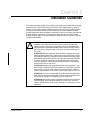
Throughout this manual, the following notes are used to alert you to safety considerations:
!
ATTENTION: Identifies information about practices or circumstances that can lead to personal
injury or death, property damage, or economic loss.
Important: Identifies information that is critical for successful application and understanding of the product.
The thick black bar shown on the left margin of this paragraph will be used throughout this manual to signify
new or revised text or figures.
!
ATTENTION: Only qualified personnel familiar with the construction and operation of this
equipment and the hazards involved should install, adjust, operate, or service this equipment.
Read and understand this manual and other applicable manuals in their entirety before
proceeding. Failure to observe this precaution could result in severe bodily injury or loss of life.
ATTENTION: DC bus capacitors retain hazardous voltages after input power has been
disconnected. After disconnecting input power from the DC bus supply, wait five (5) minutes and
then measure the voltage at the POS and NEG terminals of the DC bus supply and each Power
Module to ensure the DC bus capacitors are discharged before touching any internal components.
Failure to observe this precaution could result in severe bodily injury or loss of life.
ATTENTION: The user is responsible for conforming with all applicable local, national, and
international codes. Failure to observe this precaution could result in damage to, or destruction
of, the equipment.
The information in this user’s manual is subject to change without notice.
AutoMax™ is a trademark of Rockwell Automation.
©1998 Rockwell International Corporation
CONTENTS
Chapter 1
Introduction
1.1 Related Publications ........................................................................................ 1-2
1.2 Related Hardware............................................................................................ 1-2
Chapter 2
Mechanical/Electrical Description
2.1 Mechanical Description ................................................................................... 2-1
2.1.1 LED Indicators....................................................................................... 2-2
2.1.2 Interface Connector (TB1)..................................................................... 2-2
2.2 Electrical Description ....................................................................................... 2-3
Chapter 3
Installation Guidelines
3.1 Selecting a DC Bus Supply ............................................................................. 3-2
3.2 Selecting an External Braking Resistor ........................................................... 3-3
3.3 Wiring .............................................................................................................. 3-4
3.4 Grounding ........................................................................................................ 3-4
3.5 DC Bus Supply Initial Installation..................................................................... 3-5
3.6 Replacing the DC Bus Supply ....................................................................... 3-10
Chapter 4
Diagnostics and Troubleshooting
4.1 DC Bus Supply Faults ..................................................................................... 4-1
4.1.1 The PHASE LOSS LED Is On............................................................... 4-1
4.1.2 The OVERTEMP LED Is On ................................................................. 4-1
4.1.3 The PSM READY LED Is Off ................................................................ 4-2
4.2 DC Bus Braking Fuse Is Blown ....................................................................... 4-2
Appendix A Technical Specifications ...........................................................................................A-1
Appendix B Block Diagram ..........................................................................................................B-1
Appendix C Motor Current Specifications ....................................................................................C-1
Appendix D Compliance with Electromagnetic Compatibility Standards......................................D-1
Index
Table of Contents
........................................................................................................................... Index-1
I
II
SA500 DC Bus Supply
List of Figures
Figure 2.1 – SA500 DC Bus Supply Faceplate......................................................... 2-1
Figure 2.2 – Circuitry of Terminals 1 and 2 of Interface Connector TB1 .................. 2-3
Figure 3.1 – SA500 DC Bus Supply Mounting Dimensions...................................... 3-6
Figure 3.2 – Jumper W1 ........................................................................................... 3-7
Figure 3.3 – SA500 DC Bus Supply Wiring .............................................................. 3-8
Figure 4.1 – DC Bus Braking Fuse ........................................................................... 4-3
Table of Contents
III
IV
SA500 DC Bus Supply
List of Tables
Table 1.1 – SA500 DC Bus Supplies........................................................................ 1-1
Table 1.2 – SA500 Documentation (Binder S-3002) ................................................ 1-2
Table 2.1 – Faceplate LED Indicators ...................................................................... 2-2
Table 3.1 – SA500 DC Bus Supply Motoring Current
and Internal Power Dissipation Specifications ...................................... 3-2
Table 3.2 – Typical Braking Resistor Continuous Duty Power Dissipation............... 3-4
Table 3.3 – Short Circuit Protection.......................................................................... 3-9
Table 3.4 – Minimum/Maximum Input Wire Sizes .................................................... 3-9
Table 3.5 – Internal Braking Resistor Specifications ................................................ 3-9
Table of Contents
V
VI
SA500 DC Bus Supply
CHAPTER 1
Introduction
Distributed Power System (DPS) SA500 DC Bus Supplies rectify three-phase AC
input voltage and provide constant DC voltage to the SA500 AC Power Modules. The
DC bus supplies also contain circuits that permit regeneration from the SA500 AC
Power Modules during motor deceleration or overhauling.
The main circuit, which supplies motoring current, consists of a full-wave bridge made
from three SCRs in the upper legs and three diodes in the lower legs. The SCRs are
gradually phased on to provide pre-charging and are fully turned on during normal
operation.
The regenerative circuit consists of a transistor and a resistor in series across the DC
bus. It is switched on when the bus voltage is higher than the AC line feeding the
bridge and turned off when the bus voltage has dropped to an acceptable level.
The DC bus supplies require no programming or user tuning. These are self-contained
units that provide full regulation and diagnostic capabilities.
The four DC bus supply models are listed in table 1.1.
Table 1.1 – SA500 DC Bus Supplies
Model Number
Output Amps
(DC)
Description
615055-2R
50 A
DC Bus Supply with internal braking resistor
615055-2T
50 A
DC Bus Supply with user-supplied, external
braking resistor(s)
615055-2S
100 A
DC Bus Supply with internal braking
resistor(s)
615055-2V
100 A
DC Bus Supply with internal braking
resistor(s)
Input power for the bus supplies may be either isolated or non-isolated three-phase
230 VAC. Output power from the bus supplies is nominally 325 VDC with 230 VAC
input power. A single Bus Supply can power up to six SA500 AC Power Modules.
Refer to section 3.1 for more information on selecting a bus supply.
Note that throughout this manual references to a “bus supply” apply to all four bus
supplies unless stated otherwise.
Introduction
1-1
1.1
Related Publications
This instruction manual provides a description of the SA500 DC bus supply hardware.
Installation and troubleshooting guidelines are also provided. Note that this instruction
manual does not describe specific applications of the standard hardware or software.
For more information, refer to the instruction manuals contained in the SA500 drive
binder, S-3002, as listed in table 1.2. It is assumed that the user is familiar with the
manuals in S-3002 before installing, operating, or performing maintenance upon this
equipment. Refer to these instruction manuals as needed.
:
Table 1.2 – SA500 Documentation (Binder S-3002)
Document
Document Part Number
DPS Overview
S-3005
Universal Drive Controller Module
S-3007
Fiber Optic Cabling
S-3009
SA500 DC Bus Supply
S-3017
SA500 AC Power Modules
S-3018
SA500 Diagnostics, Troubleshooting, & Start-Up
Guidelines
S-3022
SA500 Information Guide
S-3024
SA500 Drive Configuration & Programming
S-3044
Additional information about using the SA500 Bus Supply is found in the instruction
manuals, prints, and other documents shipped with each drive system. Always consult
the prints shipped with the drive system for specific mounting and connecting
information about your drive.
1.2
Related Hardware
Bus connection wires are normally provided with engineered drive systems. These
wires connect the DC Bus Supplies to the SA500 AC Power Modules and are required
for proper operation. Substitute cables should not be used.
1-2
SA500 DC Bus Supply
CHAPTER 2
Mechanical/Electrical Description
This chapter describes the DC bus supply’s faceplate and internal electronics.
2.1
Mechanical Description
The DC bus supply consists of a phase-controlled SCR bridge, a DC bus regulator,
DC bus capacitors, and cooling fan(s). The components are housed in a sheet metal
enclosure.
The regulator circuit board assembly contains the LEDs and interface connector (TB1)
which are visible on the bus supply’s faceplate. On-board SCR and pre-charge
circuitry generate the DC bus voltage. On bus supply models 615055-2R and
615055-2S, the braking resistor(s) used to control the DC bus voltage during
regeneration are included. On bus supply models 615055-2T and 615055-2V, the
braking resistors must be added externally.
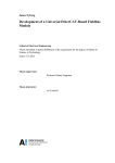
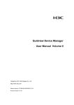
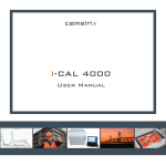
The faceplate cover of the DC bus supply is shown in figure 2.1. The cover is attached
to the DC bus supply’s chassis by the two square 1/4-turn fasteners shown.
1/4 Turn Cover Fasteners
LED Indicators
PHASE LOSS
OVER TEMP
DISABLED
PSM READY
Interface Connector (TB1)
TB1
Figure 2.1 – SA500 DC Bus Supply Faceplate
Mechanical/Electrical Description
2-1
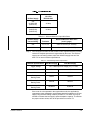
2.1.1 LED Indicators
The four LEDs visible through the faceplate provide diagnostics information about the
DC bus supply. See table 2.1.
:
7DEOH ¤ )DFHSODWH /(' ,QGLFDWRUV
LED Name
LED Color
Description
PHASE LOSS
Red
Off: OK (normal)
ON: Loss of one phase or more of the incoming
AC power
OVERTEMP
Red
Off: OK (normal)
ON: The bus supply has overheated
DISABLED
Red
Off: The bus supply has AC input power applied
and is enabled (normal)
ON: DC bus supply is disabled (check jumper
W1, see section 2.1.1)
PSM READY
Green
Off: No DC bus voltage
ON: DC bus voltage is present (normal)
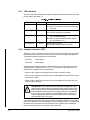
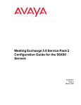
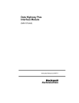
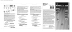
2.1.2 Interface Connector (TB1)
Terminals 1 and 2 or interface connector TB1 are used to indicate an overtemperature
fault detected by the internal protective circuitry of the DC bus supply. See figure 2.2.
The following signals are present on the terminals.
• Terminal 1:
– status signal
• Terminal 2:
+ status signal
Together these terminals provide an output signal from a normally-open relay rated
24 VDC @ 0.4A, resistive load, 25° C (77° F). This signal can be monitored in an
AutoMax rack through a 24V DC input module.
• When the bus supply is not powered up, the relay’s contacts are open.
• When the bus supply is powered up and no overtemperature fault exists, the relay’s
contacts are closed.
• When the bus supply is powered up and an overtemperature fault does exist, the
relay’s contacts are open.
!
ATTENTION: DC bus capacitors retain hazardous voltages after input
power has been disconnected. After disconnecting input power from the
DC bus supply, wait five (5) minutes and then measure the voltage at the
POS and NEG terminals of the DC bus supply and each Power Module
to ensure the DC bus capacitors are discharged before touching any
internal components. Failure to observe this precaution could result in
severe bodily injury or loss of life.
If an overtemperature fault exists, the pre-charge is disabled. However, it is possible
the DC bus capacitors may not discharge due to a component failure. The user should
disconnect AC input power and verify that the DC bus capacitors are discharged
before touching any internal components. See section 3.6.
2-2
SA500 DC Bus Supply
INTERFACE CONNECTOR TB1
SAMPLE EXTERNAL CONNECTIONS
1
1
2
2
STATUS-
+V
COM
STATUS+
3
Not Supported
Do Not Use
4
Not Supported
Do Not Use
1
+V
COM
2
Figure 2.2 – Circuitry of Terminals 1 and 2 of Interface Connector TB1
Terminals 3 and 4 of interface connector TB1 are not supported at this time and must
not be used.
Note that jumper W1, which is visible only when the cover is removed, must be set to
position B (factory setting) for the bus supply to operate correctly. See figure 3.2 in
chapter 3. With the jumper in position B, the bus supply will be on (enabled) whenever
the correct three-phase AC input voltage is present.
2.2
Electrical Description
The bus supply rectifies the incoming 230 VAC and charges the DC bus capacitors
using “soft charge” circuitry to reduce the inrush currents. Braking transistor circuitry is
included to automatically connect a braking resistor across the DC bus whenever the
motor load is regenerative and the DC bus voltage rises above the threshold level
(1.47 x RMS line voltage + 5V).
Bus supply models 615055-2R and 615055-2S have internal braking resistors. Bus
supply models 615055-2T and 615055-2V require external, user-supplied braking
resistors. Refer to section 3.2 for more information on selecting braking resistors.
Mechanical/Electrical Description
2-3
2-4
SA500 DC Bus Supply
CHAPTER 3
Installation Guidelines
This chapter provides guidelines for installing and replacing the SA500 DC bus supply.
Instructions are included describing how to select a bus supply based on the bus
supply’s current rating and the combined current draw of the motors attached to the
bus supply through the SA500 AC Power Modules. For those installations where
greater regenerative power dissipation requires the use of a bus supply with external
braking resistors, a procedure is provided to assist in the selection of the proper
braking resistors. Refer to the wiring diagrams supplied with your system for specific
installation information.
!
ATTENTION: Only qualified personnel familiar with the construction and
operation of this equipment and the hazards involved should install,
adjust, operate, or service this equipment. Read and understand this
manual and other applicable manuals in their entirety before proceeding.
Failure to observe this precaution could result in severe bodily injury or
loss of life.
ATTENTION: DC bus capacitors retain hazardous voltages after input
power has been disconnected. After disconnecting input power from the
DC bus supply, wait five (5) minutes and then measure the voltage at the
POS and NEG terminals of the DC bus supply and each Power Module
to ensure the DC bus capacitors are discharged before touching any
internal components. Failure to observe this precaution could result in
severe bodily injury or loss of life.
ATTENTION: Ungrounded equipment presents a shock hazard. If your
drive cabinet is mounted such that the cabinet is not grounded, a ground
wire must be connected to the cabinet for personnel safety. Failure to
observe this precaution could result in severe bodily injury or loss of life.
ATTENTION: The user is responsible for conforming with all applicable
local, national, and international codes. Failure to observe this precaution
could result in damage to, or destruction of, the equipment.
ATTENTION: Equipment must be connected to a power source for which
it was designed. Verify that the available input is 230 VAC. Failure to
observe this precaution could result in damage to, or destruction of, the
equipment.
Installation Guidelines
3-1
3.1
Selecting a DC Bus Supply
The number of SA500 AC Power Modules that a single DC bus supply can power
depends upon the bus supply’s current rating and the combined current draw of the
attached motors.
Use the following procedure to select a bus supply based on motor current values.
Refer to Appendix C for motor current information on Industrial Brushless, Brushless
Servo, and Induction motors.
Step 1. Add together the continuous Idc currents of all the motors to be powered
from the bus supply. See Appendix C.
Step 2. If all of the motors can accelerate, decelerate, or overhaul (draw maximum
current) at the same time, add together the maximum Idc currents of the
motors. See Appendix C.
If only some of the motors can accelerate, decelerate, or overhaul at the
same time, add their maximum Idc currents to the continuous Idc currents of
the other motors to obtain a total maximum Idc current.
Step 3. Select the DC bus supply based on both Idc continuous current and Idc
maximum current. See table 3.1 for bus supply ratings.
Note that regardless of the total current drawn by the motors, the maximum
number of SA500 AC Power Modules that can be powered from a single DC
bus supply is six.
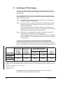
If the motors are to be operated in the regenerative mode, the applications’s
regenerative power dissipation requirements should be evaluated. The power
dissipation capabilities of the bus supplies with internal braking resistors are shown in
table 3.1. Refer to table 3.5 for the resistance values of the internal braking resistor(s).
Table 3.1 – SA500 DC Bus Supply Motoring Current and Internal Power Dissipation Specifications
DC Bus Supply
615055-2R
615055-2S
615055-2T
615055-2V
Internal Braking Resistor
Maximum Power Dissipation
Output Rating
Continuous
Current
(Idc) RMS
Output Rating
Maximum
Current
(Idc) RMS1
Continuous2
0.5 Second3
Overload
Turn-On
Voltage4
50A
150A
414W5
1568W5
343V
100A
450A
1200W6
4624W6
343V
1. 10 second overload
2. Maximum continuous braking power = (continuous fuse current)2 x R, where continuous fuse current = 0.9 x fuse rating.
3. Maximum 0.5 second overload braking power = (maximum fuse current)2 x R, where maximum fuse current = 2 second fuse melting
current.
4. VLL x 1.47 + 5 volts, where VLL is 230VAC nominal.
5. Snubber Fuse Limited
6. Resistor Limited
If the application’s requirements exceed these values, refer to section 3.2 for
information on selecting external braking resistors.
3-2
SA500 DC Bus Supply
3.2
Selecting an External Braking Resistor
DC bus supplies with external braking resistors (615055-2T or 615055-2V) allow for
greater power dissipation during motor regeneration. Perform the following steps to
determine the required external braking resistor specifications.
Step 1. Using the stopping time specifications, calculate the required braking torque:
Torque =
J
x
Alpha
(lb-ft) =
(N-m) =
(lb-ft-sec2)
(kg-meter2)
x
x
(radians/second2)
(radians/second2)
J is the combined total inertia of the motor and the machine (which can be
either calculated or measured). Alpha is the rate of deceleration of the
motor’s shaft.
Step 2. Calculate the resistance value of the external braking resistor.
R =
(Turn-on Voltage) 2
x 6.33 ohms
Torque x RPM
Turn-on Voltage = 1.47 x VLL + 5 volts, where VLL is the RMS input
line-to-line voltage. Turn-on voltage is 343 VDC for a nominal 230 VAC.
Torque is in lb-ft. 1 lb-ft = 0.7376 N-m.
Note that the recommended ranges of resistance values are as follows:
• 50 A DC bus supply: 8 (minimum) to 55 ohms
• 100 A DC bus supply: 4 (minimum) to 15 ohms
A lower resistor value provides higher short-duration regenerative currents
but results in a reduction of the continuous power rating. A higher resistor
value provides for maximum continuous power operation. Over the
recommended ranges of resistance values, operation is balanced between
short duration overload current conditions and continuous power conditions.
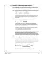
Step 3. Determine the continuous power dissipation specifications of the external
braking resistor.
The continuous power rating is limited by both the fuse rating (0.9 x fuse
rating) and the resistor value. The regenerative duty cycle is limited by the
internal fuse. The lower value resistors will have higher peak currents and
therefore the duty cycle must be limited to prevent nuisance fuse openings.
The following equations are used to determine the typical braking resistor
specifications for each power supply, as shown in table 3.2.
τ
= Max Duty Cycle =
2
(0.9 x Fuse Rating) x R 2
(Turn-on Voltage) 2
seconds
Max Continuous Braking Power = (0.9 x Fuse Rating) 2 x R
Installation Guidelines
watts
3-3
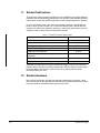
Table 3.2 – Typical Braking Resistor Continuous Duty Power Dissipation
50 Amp Supply
R
(ohms)
8 Amp Fuse
τ
100 Amp Supply 30 Amp Fuse
τ
(seconds)
Max CBP
(watts)
R
(ohms)
(seconds)
Max CBP
(watts)
8
0.03
414
4
0.10
2916
16
0.11
829
6
0.22
4374
24
0.25
1244
8
0.40
5832
32
0.45
1658
10
0.62
7290
40
0.71
2073
12
0.89
8748
47.61
1.0/Cont
2468
12.71
1.0/Cont
9258
48
Continuous
2451
14
Continuous
8403
55
Continuous
2139
15
Continuous
7843
1. Maximum continuous power resistor value
For intermittent duty the external braking resistor power dissipation is
specified by:
Resistor Power Dissipation = 1 / x (0.5 Second Overload Braking Power) watt-secs
2
2
0.5 Second Overload Braking Power = (Maximum Fuse Current) x R watts
Maximum Fuse Current is the level of current that will cause the braking fuse
to melt in 2 seconds, as indicated on the KLK fuse rating curves. Use 14
amps for an 8 amp fuse, and 85 amps (maximum regenerative current with
4 ohms) for a 30 amp fuse.
Note:
Instantaneous Maximum Braking Power = (Maximum DC Bus Voltage)
R
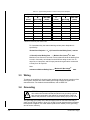
3.3
2
watts
Wiring
To reduce the possibility of electrical noise interfering with the proper operation of the
drive system, exercise care when installing the wiring between the system and
external devices. For detailed recommendations, refer to IEEE 518.
3.4
Grounding
!
ATTENTION: Ungrounded equipment presents a shock hazard. If your
drive cabinet is mounted such that the cabinet is not grounded, a ground
wire must be connected to the cabinet for personnel safety. Failure to
observe this precaution could result in severe bodily injury or loss of life.
The grounding stud (GND) on the DC bus supply must be connected externally to
earth ground (PE) as shown in figure 3.3 on page 3-8 and checked with an ohmmeter
before power is applied. Use a star washer (toothed lock washer) on the grounding
stud to ensure continuity.
3-4
SA500 DC Bus Supply
3.5
DC Bus Supply Initial Installation
The following procedure is intended to be only a guide to assist you in installing the
DC bus supply. Refer to the wiring diagrams supplied with you system for more
specific information.
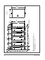
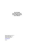
Step 1. Mount the DC bus supply. DC bus supplies are designed to be mounted on a
flat surface using M5 or #10 screws. The holes in the top flange are key-hole
shaped and the lower holes are U-shaped to facilitate mounting. The bus
supply should be mounted in a location with good air flow and in close
proximity to the SA500 AC Power Modules (3 mm (1/8 in) to 13 mm (1/2 in)
spacing between units). See figure 3.1. Provide at least 85 mm (3.3 in) of
clearance above and below the bus supply for ventilation.
Ambient air around the bus supply must be clean, dry, and free of flammable
or combustible vapors, chemical fumes, oil vapor, steam, and excessive
moisture and dirt.
The highest current AC Power Module should be placed closest to the bus
supply. Note that the SA500 AC Power Modules (6 maximum) should be
evenly distributed on each side of the bus supply. If two Power Modules are
being used, one should be wired from the left of the bus supply and one
should be wired from the right. If four Power Modules are being used, two
should be wired from the left of the bus supply and two from the right. If an
odd number of Power Modules is being used, they should be distributed as
evenly as possible on each side of the bus supply. This method of Power
Module placement minimizes wire length which reduces wire inductance.
The continuous DC bus current for all SA500 AC Power Modules connected
to the bus supply is limited to either 50A or 100A.
Installation Guidelines
3-5
Figure 3.1 – SA500 DC Bus Supply Mounting Dimensions
3-6
SA500 DC Bus Supply
Typical
115 mm
(4.5")
B
1
B
SA500
AC Power
Module
1/4 Turn Cover
Fasteners
SA500
DC Bus
Supply
#10 (M5)
Mounting Screws
SA500
AC Power
Module
B
Front View
2
Mounting Screw Head Diameter is 10 mm (0.39") maximum
Covers are removed by pulling them straight out as indicated by arrow
A = 102 mm (4") minimum
B = 118 mm (4.62") minimum, 127 mm (5") maximum
C = 13 mm (0.5") minimum
1
35 mm
(1.38")
SA500
AC Power
Module
35 mm
(1.38")
C
B
SA500
AC Power
Module
411 mm
(16.18")
429 mm
(16.88")
7 mm
(0.27)
12 mm
(0.47")
Minimum Recommended
Panel Space Requirement
A
A
C
Air Intake
2
Air Exhaust
243 mm
(9.5")
Side View
445 mm
(17.5")
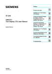
Step 2. Rotate the quarter-turn cover fasteners and remove the bus supply’s front
cover. Check the bus supply’s nameplate to ensure that the bus supply has
the proper power rating (50A or 100A).
Examine jumper W1 on the printed circuit board (see figure 3.2). The jumper
must be set to position B for the bus supply to operate properly. This is the
factory setting. When the jumper is set to position B, the bus supply will be
enabled whenever the correct three-phase input voltage is present.
LEDs
DC Bus Supply
PC Board
(Component Side)
Interface
Connector
(TB1)
1 } Fault Contact Output
2
3
} Not Supported
4
1
Jumper W1
A
B
4
A
B
Figure 3.2 – Jumper W1
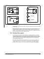
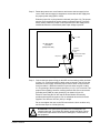
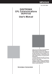
Step 3. Connect the input power wiring per the NEC and local wiring codes as shown
in figure 3.3. A fuse disconnecting switch must be placed in the AC line that
feeds the DC bus supply. Select the proper value of short circuit protection
fuse from table 3.3. Minimum/maximum input wire sizes are given in table
3.4. The phasing of the three-phase input lines (L1, L2, L3) is not critical. The
proper DC bus polarity, however, must be observed. Be sure to connect the
grounding stud (GND) to earth ground (PE) as shown in figure 3.3.
Wires for connecting the DC bus and the Power Module are normally
provided with engineered systems. Do not substitute other wires for those
supplied. The wires are 225 mm (8.8 in) in length.
Do not over-tighten the nuts on the DC bus terminals. Use a nut-driver only
and limit the torque to 4.0 Nm (36 lb-in).
!
Installation Guidelines
ATTENTION: Fuse disconnecting switches are not designed to be
opened under load. Turn off the drive before opening the switch. Failure
to observe this precaution could result in damage to, or destruction of,
the equipment.
3-7
Figure 3.3 – SA500 DC Bus Supply Wiring
3-8
SA500 DC Bus Supply
U V W
M6 Nut
Terminal Post Base
U V W
Fuse
Fuse
Fuse
GND
47
48
Drive or Power
Supply Bus Bar
Flat Washers
L1 L2 L3
SA500
DC Bus
Supply
POS NEG
Lock Washers
Positive and Negative Terminals
M6 Terminal Post
PE
Connecting Lugs
To Grounding Rod
or Building Steel
POS NEG
SA500 AC
Power Module
Fuse Disconnecting Switch
GND
Short Circuit Capacity
5000 Amps or Less
AC Input
Voltage
(3-Phase)
*Wires are 225 mm (8.8") long
Red Wire*
Black Wire*
Green Wire*
POS NEG
SA500 AC
Power Module
External
Braking Resistor
GND
POS NEG
GND
Ground Terminals
U V W
SA500 AC
Power Module
Motor
U V W
GND
Connecting Lugs
M6 Nut
M6 Terminal Post
POS NEG
SA500 AC
Power Module
7DEOH ¤ 6KRUW &LUFXLW 3URWHFWLRQ
Maximum Input Fuse
UL Class
RK5 250 VAC
DC Bus Supply
50A
(615055-2R)
(615055-2T)
40 Amp
100A
(615055-2S)
(615055-2V)
90 Amp
Table 3.4 – Minimum/Maximum Input Wire Sizes
DC Bus Supply
Current Rating
Terminals
Minimum/Maximum Wire Sizes
(mm2 / gauge)
50A
L1, L2, L3
4.8 to 21.6 mm2 (10 - 4 AWG)
100A
L1, L2, L3
13.6 to 35 mm2 (6 - 2AWG)
Step 4. DC bus supplies 615055-2R and 615055-2S are supplied with built-in braking
resistors to dissipate power that is regenerated by the motor. The 50A bus
supply has one braking resistor, while the 100A bus supply has two. See
table 3.5. for internal resistor specifications.
Table 3.5 – Internal Braking Resistor Specifications
Resistor Specifications
Trigger Voltage
50A Bus Supply
100A Bus Supply
1.47 ∗ RMS input line voltage (VLL) + 5 volts
Ohms
8Ω
4Ω
Watts
600 W
1200 W
Continuous
Braking Power
414 W
1200 W
0.5 Second Overload
Braking Power
1568 W
4624 W
Instantaneous Overload
Braking Power
19,500 W
39,000 W
If the motor is to be operated in the regenerative mode, the application’s
regenerative power dissipation requirements should be evaluated. A DC bus
supply using external braking resistors (615055-2T or 615055-2V) may be
needed to increase the bus supply’s power dissipation capacity. To calculate
the proper resistor values, refer to the procedures in section 3.2.
Installation Guidelines
3-9
If external resistors are to be used, connect the wires from the resistors to the
terminal block at the top of the bus supply. A notch in the front cover allows
the wires to be routed from the terminal block even when the front cover is
installed.
Step 5. Apply power to the input wiring and check that the voltages are within
operating parameters. Voltage specifications are given in Appendix A.
Step 6. Re-attach the bus supply’s front cover.
3.6
Replacing the DC Bus Supply
Use the following procedure to replace a DC bus supply:
Step 1. Turn off and lock out AC input power to the bus supply.
!
ATTENTION: DC bus capacitors retain hazardous voltages after input
power has been disconnected. After disconnecting input power from the
DC bus supply, wait five (5) minutes and then measure the voltage at the
POS and NEG terminals of the DC bus supply and each Power Module
to ensure the DC bus capacitors are discharged before touching any
internal components. Failure to observe this precaution could result in
severe bodily injury or loss of life.
Step 2. Wait five minutes to allow the DC bus voltage to dissipate.
Step 3. Measure the DC bus potential across the POS and NEG terminals of the DC
bus supply and at each Power Module before working on the unit.
When the DC bus potential is down to less than 5V, touch a 50 Ω, 50 W or
larger resistor across the POS and NEG terminals for 20 seconds to allow
any remaining DC bus voltage to dissipate.
Remove the resistor and re-measure the DC bus potential to ensure the DC
bus capacitors are completely discharged before touching any internal
components.
Step 4. Disconnect the input power wires from the L1, L2, and L3 terminals.
Step 5. Disconnect the DC bus wires from the POS, NEG, and GND terminals.
Step 6. Disconnect the external braking resistor (if used) from the terminal block at
the top of the DC bus supply.
Step 7. Remove the screws that attach the bus supply to its mounting surface.
Step 8. Install the replacement bus supply by following steps 3 through 7 in reverse
order.
3-10
SA500 DC Bus Supply
CHAPTER 4
Diagnostics and Troubleshooting
!
ATTENTION: DC bus capacitors retain hazardous voltages after input
power has been disconnected. After disconnecting input power from the
DC bus supply, wait five (5) minutes and then measure the voltage at the
POS and NEG terminals of the DC bus supply and each Power Module
to ensure the DC bus capacitors are discharged before touching any
internal components. Failure to observe this precaution could result in
severe bodily injury or loss of life.
Use the procedures described in the following section to diagnose and troubleshoot
DC bus supply faults. If the problem cannot be corrected by following these
instructions, the DC bus supply is not user-serviceable.
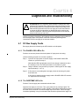
4.1
DC Bus Supply Faults
Bus supply faults are indicated by the LEDs visible on the faceplate.
4.1.1 The PHASE LOSS LED Is On
Problem: At least one phase of the three-phase AC input power is missing.
Use the following procedure to correct the problem:
Step 1. Cycle the AC input power to the bus supply. If the PHASE LOSS LED
remains on, proceed to step 2.
Note that this LED may light when low AC line voltage is detected or when
line notching occurs. The LED will remain on until power is cycled.
Step 2. Using a voltmeter, verify that AC input power is reaching the DC bus supply
input terminals (L1, L2, L3).
Step 3. If AC power is not reaching the bus supply, check the incoming AC power
lines and fuses.
If AC power is reaching the bus supply and the PHASE LOSS LED remains
on, replace the DC bus supply.
4.1.2 The OVERTEMP LED Is On
Problem: The bus supply has overheated and shut down.
Allow the bus supply to cool down. Then cycle power and try running it again. The
LED will remain on until power is cycled. Typically, if the ambient temperature is above
the rated value, fan failure or air flow blockage may be the cause. If the bus supply
overheats repeatedly, it may be overloaded and should be replaced with a larger unit.
Diagnostics and Troubleshooting
4-1
4.1.3 The PSM READY LED Is Off
Problem: The DC bus voltage is different from what is expected.
During normal operation, the PSM READY LED is on when AC power is applied and
there are no bus supply faults. If this LED turns off, use the following procedure to
isolate the problem:
Step 1. Using a voltmeter, verify that the DC bus supply is receiving the correct AC
input voltage (terminals L1, L2, L3).
Step 2. If the bus supply is not receiving the correct input voltage, check the AC input
power lines.
If the bus supply is receiving the correct voltage, proceed to step 3.
Step 3. Check the other fault LEDs. the PHASE LOSS and OVERTEMP LEDs should
be off. If either LED is on, refer to the appropriate troubleshooting section in
this chapter.
Step 4. If the PSM READY LED remains off, replace the DC bus supply.
4.2
DC Bus Braking Fuse Is Blown
Problem: SA500 AC Power Module regeneration does not work properly (i.e., braking
is slower than expected) and the Power Module experiences frequent DC bus
overvoltage faults.
These problems may be caused by a blown braking fuse. Use the following procedure
to determine if the braking fuse is blown:
Step 1. Turn off and lock out AC input power to the bus supply.
!
ATTENTION: DC bus capacitors retain hazardous voltages after input
power has been disconnected. After disconnecting input power from the
DC bus supply, wait five (5) minutes and then measure the voltage at the
POS and NEG terminals of the DC bus supply and each Power Module
to ensure the DC bus capacitors are discharged before touching any
internal components. Failure to observe this precaution could result in
severe bodily injury or loss of life.
Step 2. Wait five minutes to allow the DC bus voltage to dissipate.
Step 3. Measure the DC bus potential across the POS and NEG terminals of the DC
bus supply and each Power Module before working on the unit.
When the DC bus potential is down to less than 5V, touch a 50 Ω, 50 W or
larger resistor across the POS and NEG terminals for 20 seconds to allow
any remaining DC bus voltage to dissipate.
Remove the resistor and re-measure the DC bus potential to ensure the DC
bus capacitors are completely discharged before touching any internal
components.
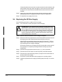
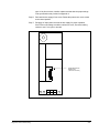
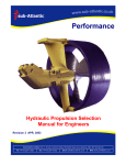
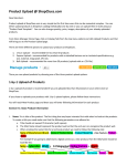
Step 4. Rotate the quarter-turn cover fasteners to the open position and remove the
bus supply’s front cover.
Step 5. Remove the fuse (see figure 4.1). Use an ohmmeter to check if the fuse is
4-2
SA500 DC Bus Supply
open. If the fuse is blown, install a replacement that has the proper ratings.
Fuse specifications are provided in Appendix A.
Step 6. Re-install the bus supply’s front cover. Rotate the quarter-turn cover screws
to the closed position.
Step 7. Re-apply AC input power and test the bus supply for proper operation.
If the DC bus overvoltage condition continues to occur, check the braking
resistor to see if it is open or shorted.
Replaceable DC Bus
Braking Fuse
(with cover removed)
Figure 4.1 – DC Bus Braking Fuse
Diagnostics and Troubleshooting
4-3
4-4
SA500 DC Bus Supply
APPENDIX A
Technical Specifications
Ambient Conditions
• Operating Temperature: 0 to 50° C (32 to 122° F)
• Relative Humidity: 5 to 95% (non-condensing)
Dimensions
• Height: 445 mm (17.5 in)
• Width: 115 mm (4.5 in)
• Depth: 250 mm (9.8 in)
• Weight: 11.9 kg (26.2 lbs)
Input Voltage
• 230 VAC RMS (+15%, -5%) three-phase
• 5000 Amps Maximum Symmetrical Available Fault Current Source
Output Voltage
• 310 to 375 VDC
Continuous Output DC Amperes
• 50A units: 50A
• 100A units: 100A
Maximum Output DC Amperes (10 Second Overload)
• 50A units: 150A
• 100A units: 450A
Internal Braking Resistor Continuous Power Dissipation
• 50A units: 414W
• 100A units: 1200W
Internal Braking Resistor 0.5 Second Overload Power Dissipation
• 50A units: 1568W
• 100A units: 4624W
Technical Specifications
A-1
Internal Braking Resistor Instantaneous Overload Power Dissipation
• 50A units: 19,500W
• 100A units: 39,000W
DC Bus Braking Fuse
• DC Bus Supply (50A) with Internal Braking Resistor: Littelfuse KLK D8, Fast
Acting, 600V, 8A or Bussman KLM-8
• DC Bus Supply (50A) with External Braking Resistor: Littelfuse KLK D8, Fast
Acting, 600V, 8A or Bussman KLM-8
• DC Bus Supply (100A) with Internal Braking Resistor: Littelfuse KLK D20, Fast
Acting, 600V, 20A or Bussman KLM-20
• DC Bus Supply (100A) with External Braking Resistor: Littelfuse KLK D30, Fast
Acting, 600V, 30A or Bussman KLM-30
Maximum Power Losses1
• 50A units: 110W + intermittent watts from braking circuit
• 100A units: 240W + intermittent watts from braking circuit
1. Typical power losses are one-half of these values
A-2
SA500 DC Bus Supply
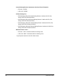
APPENDIX B
Block Diagram
Fuse
Resistor
230 VAC
Input
Voltage
Resistor
DC-to-DC
Power
Supply
Block Diagram
Pre-charge
SCR
Driver
Voltage
Feedback
DC Bus
Output
Voltage
to SA500 AC
Power Module
Braking
Transistor
Driver
LEDs
B-1
B-2
SA500 DC Bus Supply
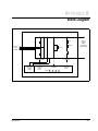
APPENDIX C
Motor Current Specifications
Table C.1 – Industrial Brushless Motors
Model No.
HP
Max
Speed
RPM
Encl
Cont
Iac RMS
Amps
Cont Idc Amps
(Bus Supply
Requirement)
Max Iac
RMS
Amps
Max Idc Amps
(Bus Supply
Requirement)
Min DC
Bus
Supply
B14H3050
1
2000
TENV
3.3
4.2
6.5
8.2
1
B14H3060
2
2000
TENV
6.5
8.2
13.1
16.5
1
B18H3070
3
2000
TENV
9.8
12.4
19.6
24.7
1
B18H3080
4
2000
TENV
13.1
16.5
26.3
33.2
1
P21M0309
7.5
1750
TENV
24.0
30.3
48.0
60.5
1
P21M0310
10
1750
TENV
32.0
40.3
64.0
80.7
1
P21M0311
15
1750
TENV
48.0
60.2
96.0
121.0
2
1. Minimum bus supply: 615055-2R or 615055-2T. Output continuous current (Idc) = 50A.
2. Minimum bus supply: 615055-2S or 615055-2V. Output continuous current (Idc) = 100A.
Refer to the DPS SA500 Power Modules instruction manual (S-3018) for Iac current overload rating information
(speed-torque charts).
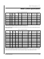
Table C.2 – Brushless Servo Motors
Model No.
HP
Max
Speed
RPM
Encl
Cont Iac
RMS
Amps
Cont Idc Amps
(Bus Supply
Requirement)
Max Iac
RMS
Amps
Max Idc Amps
(Bus Supply
Requirement)
Min DC
Bus
Supply
S2005-K-R
5.9
4000
TENV
3.0
3.8
6.5
8.2
1
S3007-N-R
7.6
3000
TENV
2.0
2.5
6.3
7.9
1
S3016-N-R
20
3000
TENV
5.7
7.2
14.3
18.0
1
S4030-P-R
30
3000
TENV
4.8
6.1
13.6
17.1
1
S4050-P-R
60
3000
TENV
9.6
12.1
30.4
38.3
1
S4075-R-R
90
2500
TENV
9.5
12.0
28.4
35.8
1
S6100-Q-R
100
2000
TENV
11.8
14.9
26.8
33.8
1
S6200-Q-R
200
2000
TENV
24.2
30.5
58.1
73.3
1
S6300-Q-R
320
2000
TENV
36.0
45.4
77.6
97.8
1
S8353-S-R
350
2000
TENV
32.5
41.0
57.6
72.6
1
S8500-S-R
480
2000
TENV
39.1
49.3
95.6
120.5
1
1. Minimum bus supply: 615055-2R or 615055-2T. Output continuous current (Idc) = 50A.
Refer to the DPS SA500 Power Modules instruction manual (S-3018) for Iac current overload rating information
(speed-torque charts). I/M S-3018 also contains horsepower ratings for the brushless servo motors.
Motor Current Specifications
C-1
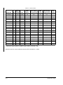
Table C.3 – Induction Motors
Model No.
HP
Max
Speed
RPM
Encl
Cont Iac
RMS
Amps
Cont Idc Amps Max Iac
(Bus Supply
RMS
Requirement)
Amps
Max Idc Amps
(Bus Supply
Requirement)
Min DC
Bus
Supply
P14A5810
1
1757
TENV
3.0
3.8
4.5
5.7
1
P14A5804
1.5
1756
TENV
4.4
5.5
6.6
8.3
1
P14A5813
2
1764
TENV
5.8
7.3
8.7
11.0
1
P18A6111
3
1758
TENV
9.0
11.3
13.5
17.0
1
P18A6113
5
1737
TENV
14.4
18.2
21.6
27.2
1
P21L0212
5
1781
TENV
15.3
19.3
23.0
28.9
1
P21L0213
5
1180
TENV
14.8
18.7
22.2
28.0
1
P21L0214
5
880
TENV
14.8
18.7
22.2
28.0
1
P21L0215
7.5
1780
TENV
21.5
27.1
32.3
40.7
1
P21L0216
7.5
1177
TENV
20.6
26.0
30.9
39.0
1
P21L0217
7.5
866
TEAO
21.8
27.5
32.7
41.2
1
P21L0218
10
1779
TENV
27.8
35.1
41.7
52.6
1
P21L0219
10
1171
TEAO
27.3
34.4
41.0
51.6
1
P21L0220
10
868
TEAO
28.0
35.3
42.0
53.0
1
P21L0221
15
1768
TEAO
42.0
53.0
63.0
79.4
2
P21L0222
15
1172
TEAO
42.0
53.0
63.0
79.4
2
P21L0223
15
872
TEAO
41.1
51.8
61.7
77.7
2
1. Minimum bus supply: 615055-2R or 615055-2T. Output continuous current (Idc) = 50A.
2. Minimum bus supply: 615055-2S or 615055-2V. Output continuous current (Idc) = 100A.
Induction motor Iac current values are rated at 150% overload for 1 minute.
C-2
SA500 DC Bus Supply
APPENDIX D
Compliance with Electromagnetic
Compatibility Standards
D.1 Introduction
This appendix provides information on the SA500 DC Bus Supplies and AC Power
Modules’ compliance with European Community electromagnetic compatibility (EMC)
standards and covers the following:
• requirements for standards compliance
• guidelines on installing the equipment
• instructions on how the drive must be wired.
The SA500 DC Bus Supplies and AC Power Modules listed on the Declaration of
Conformity (DOC) (Ref: Drawing 422802-201) have been tested and are in
compliance with the following standards when installed as described in this manual
and amended herein:
• EN55011 (1991) Limits and methods of measurement of radio disturbance
characteristics of industrial, scientific, and medical (ISM) radio-frequency
equipment.
• EN50082-2 (1995) Electromagnetic Compatibility - Generic Immunity Standard
Part 2: Industrial Environment
Note that the conformity of the SA500 DC Bus Supplies and AC Power Modules to the
above standards does not guarantee that the entire installation will be in conformance.
For a copy of the Declaration of Conformity, contact your local Rockwell Automation
sales office.
D.2 Compliance Requirements
In order for the SA500 DC Bus Supplies and AC Power Modules to conform to the
standards listed in section D.1, the equipment must:
• be accompanied by the DOC (Ref: Drawing 422802-201).
• have a CE mark. This mark is found on the product.
• be mounted inside a cabinet.
• be powered through a EMI line filter.
• be installed in accordance with the instructions in this appendix.
If these conditions are not met and CE conformity is desired, contact your local
Rockwell Automation Drive Systems Sales Representative.
Compliance with Electromagnetic Compatibility Standards
D-1
D.3 Installing the Equipment
The equipment must be mounted inside a steel cabinet. The cabinet door must be
grounded to the main cabinet. Any accessory plates attached to the cabinet door must
be grounded to the same point on the cabinet as the door. The cabinet must also have
floor pans with the cutouts for cable entries kept to an absolute minimum.
The SA500 DC Bus Supplies and AC Power Modules and EMI Filter should be
mounted to the panel in accordance with the installation instructions provided in
chapter 3 of this manual.
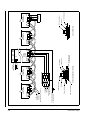
D.4 Wiring Practices
This section describes how the SA500 drive must be wired to conform to the
standards listed in section D.1. Figure D.1 shows an SA500 wiring example.
D.5 AC Input Power
A 110 Amp three-phase line filter (M/N 612421-2A) must be installed in the power
lines. The leads between the filter and the DC Bus Supply should be as short as
possible and must be routed away from the leads to the input of the filter. Both ground
connections must be used and the ground leads should be kept as short as
possible.(£ 6.0”). This filter may be mounted to a separate bracket and placed on edge
to reduce the panel footprint so long as the bracket is properly grounded to the control
panel.
A three-phase input power surge protector (M/N 600686-45A) must be installed on the
230 VAC lines at the line input to the EMI Filter. The leads on the surge protector
should be kept as short as possible.
The 115 VAC source voltage used to power the digital I/O must be supplied through a
1 kVA control transformer (M/N 417155-V) with a MOV (M/N 411026-X) mounted
across transformer terminals X1 and X2. The X2 terminal of the control transformer
must also be grounded to the control panel.
D.6 Motor Output
The motor leads (three phases and ground) must be installed in conduit. The conduit
should be terminated at the cabinet.
D.6.1 Grounding
The incoming 230 VAC three-phase power must be connected to the grounding stud
on the DC Bus Supply.
The DC Bus Supply and AC Power Module must be grounded in accordance with the
guidelines provided in section 3.4 of this manual. The ground lead from the motor
must be connected to the AC Power Module and then connected to the DC Bus
Supply via the jumper supplied with the AC Power Module.
D-2
SA500 DC Bus Supply
D.6.2 Rail Ports
The two rail Rail Ports must not be used for CE applications. As an alternative, digital
I/O can be configured using either the digital I/O on the Resolver and Drive I/O Module
or the Allen-Bradley Remote I/O Interface Module (M/N 57C443) and Allen-Bradley
I/O.
D.6.3 Resolver and Analog Input Wiring
Resolver cable M/N 417900-207CG is recommended. This specific cable was chosen
per instruction manual D2-3115-2, (Installing, Operating, and Maintaining Engineered
Drive Systems), as the only cable not required to be installed in conduit. Conduit is not
required for CE purposes, but it may be required for a specific application.
Use shielded 2-conductor cable for analog input wiring. The shield drain wire is to be
grounded to the cable terminal board and left open at the opposite end.
D.6.4 Digital I/O Wiring
The 115 VAC source voltage for the digital I/O must be supplied from the secondary of
the isolation transformer. When a main contactor is used, an RC suppressor
(M/N 600686-33A or equivalent) must be installed across the coil contacts.
Compliance with Electromagnetic Compatibility Standards
D-3
Figure D.1 – Typical SA500 Wiring Example for CE Compliance
D-4
SA500 DC Bus Supply
U V W
M6 Nut
Terminal Post Base
U V W
Fuse
Fuse
Fuse
GND
47
48
Drive or Power
Supply Bus Bar
Flat Washers
L1 L2 L3
SA500
DC Bus
Supply
POS NEG
Lock Washers
Positive and Negative Terminals
M6 Terminal Post
PE
Connecting Lugs
To Grounding Rod
or Building Steel
POS NEG
SA500 AC
Power Module
Fuse Disconnecting Switch
GND
Short Circuit Capacity
5000 Amps or Less
AC Input
Voltage
(3-Phase)
*Wires are 225 mm (8.8") long
Red Wire*
Black Wire*
Green Wire*
POS NEG
SA500 AC
Power Module
External
Braking Resistor
GND
POS NEG
GND
Ground Terminals
U V W
SA500 AC
Power Module
Motor
U V W
GND
Connecting Lugs
M6 Nut
M6 Terminal Post
POS NEG
SA500 AC
Power Module
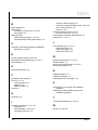
INDEX
B
Block diagram, B-1
Braking fuse
checking for a blown fuse, 4-2 to 4-3
fuse location, 4-3
Braking resistor
external braking resistor, 3-3 to 3-4
internal braking resistor specifications, 3-9
C
Compliance with electromagnetic compatibility
standards, D-1 to D-4
selecting a DC bus supply, 3-2
selecting an external braking resistor, 3-3 to 3-4
short circuit protection, 3-9
wiring, 3-4, 3-8
Interface connector TB1, 2-2 to 2-3
circuitry of terminals 1 & 2, 2-3
Internal power dissipation specifications, 3-2
Introduction, 1-1 to 1-2
L
LED indicators, 2-2, 4-1 to 4-2
Overtemp LED on, 4-1
Phase loss LED on, 4-1
PSM ready LED off, 4-2
D
DC bus supply motoring current, 3-2
Diagnostics and troubleshooting, 4-1 to 4-3
Documentation, 1-2
E
M
Mechanical description, 2-1 to 2-3
Model numbers, 1-1
Motor current specifications, C-1 to C-2
Mounting dimensions, 3-6
Electrical description, 2-3
R
F
Related hardware, 1-2
Related publications, 1-2
Replacing the DC bus supply, 3-10
Faceplate of bus supply, 2-1
Faults, 4-1 to 4-2
over temperature, 4-1
phase loss, 4-1
PSM not ready, 4-2
Fuses, 3-9
G
S
Selecting a DC bus supply See Installation
guidelines
Selecting an external braking resistor See
Installation guidelines
Grounding, 3-4
T
I
Technical specifications, A-1 to A-2
Installation guidelines, 3-1 to 3-10
grounding, 3-4
initial installation, 3-5 to 3-10
mounting dimensions, 3-6
W
Index
Wiring, 3-4, 3-8, D-4
Index-1
Index-2
SA500 DC Bus Supply
DIF
Documentation
Improvement Form
Use this form to give us your comments concerning this publication or to report an
error that you have found. For convenience, you may attach copies of the pages with
your comments. After you have completed this form, please return it to:
Rockwell Automation
RGA (Technical Publications)
25001 Tungsten Road
Cleveland, Ohio 44117
Fax: 216.266.7120
Publication Name:
Publication Number:
Publication Date:
Comments:
Your Name:
Date:
Company Name:
Phone: (
)
Address:
Thank you for your comments.
Technical Writing Internal Use
Date:
Follow-Up Action:
DIF Number:
Rockwell Automation / 24703 Euclid Avenue / Cleveland, Ohio 44117 / (216) 266-7000
Printed in U.S.A.
S-3017-1
September 1998