1
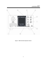
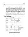
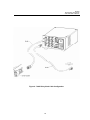
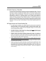
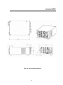
M76995 150 Long Beach Boulevard Stratford, CT 06615 Phone: (203) 377-8282 (800) 714-5393 Fax: (203) 378-2457 E-MAIL: [email protected] ORIEL FAST SHUTTER SYSTEMS MODELS 76992, 76993, 76994, 76995 USER MANUAL Please read these instructions completely before operating this equipment. The specification and operating instructions apply only to the model(s) covered by this manual. If there are any questions or problems regarding the use of this equipment, please contact Newport or the representative from whom this equipment was purchased Rev:10.23.12 M76995 ELECTRONIC SHUTTERS AND SHUTTER CONTROL TABLE OF CONTENTS 1. INTRODUCTION....................................................................................................................................... 3 2. GETTING STARTED ................................................................................................................................ 4 3. SHUTTERS............................................................................................................................................... 5 4. SPECIFICATIONS .................................................................................................................................... 6 5. 76995 SHUTTER DRIVER ....................................................................................................................... 8 5.1 Start Up ........................................................................................................................................ 8 5.2 Line Fuse Replacement ............................................................................................................... 9 5.3 Voltage Change ......................................................................................................................... 10 5.4 Initial Operation and Testing ...................................................................................................... 11 6. 76995 FRONT PANEL OPERATOR CONTROLS ................................................................................. 12 6.1 Description ................................................................................................................................. 12 7. 76995 REAR PANEL OPERATOR CONTROLS.................................................................................... 15 7.1 Description ................................................................................................................................. 15 8. 76995 OPERATING BASICS.................................................................................................................. 18 8.1 Function Switches ...................................................................................................................... 18 8.2 Gate Input................................................................................................................................... 19 8.3 Gate Timing Diagrams ............................................................................................................... 19 8.4 Mode Selection .......................................................................................................................... 20 8.5 RS-232C Operation.................................................................................................................... 20 8.6 RS-232 Test Program ................................................................................................................ 23 8.7 Shutter Frequency of Operation................................................................................................. 25 8.8 Trigger Cautions and Trouble Shooting Tips ............................................................................. 25 8.9 Pulse Voltage Graphs ................................................................................................................ 26 8.10 Maintenance............................................................................................................................. 28 9. INSPECTION AND CLEANING OF THE 76995..................................................................................... 29 9.1 General Care.............................................................................................................................. 29 9.2 Inspection and Cleaning Procedures ......................................................................................... 29 9.3 Inspection - Exterior ................................................................................................................... 29 9.4 Cleaning Procedure - Exterior.................................................................................................... 29 9.5 Cleaning Procedure – Interior .................................................................................................... 30 10. 76995 SPECIFICATIONS ..................................................................................................................... 31 10.1 System Characteristics ............................................................................................................ 31 10.2 External Input Characteristics .................................................................................................. 31 10.3 External Output Characteristics ............................................................................................... 32 10.4 General Characteristics............................................................................................................ 33 10.5 Applicable Certifications........................................................................................................... 35 11. WARRANTY AND RETURNS .............................................................................................................. 36 2 M76995 ELECTRONIC SHUTTERS AND SHUTTER CONTROL 1. INTRODUCTION The Oriel Electronic Shutters, Models 76992, 76993 and 76994, in conjunction with the Oriel Model 76995 Shutter Controller, provide accurate and repeatable exposures as short as 2.6 milliseconds at exposure frequencies as high as 150 Hz. Typical applications for these shutters include CCD frame transfers, precision exposure control, laser pulse gating lithography and holography. The overlapping shutter blades are coated with aluminum magnesium fluoride (AlMgF2) for high reflectance at the input to reduce the radiation absorbed and the resultant temperature rise. These shutters have a standard Newport 1.5 inch series male mounting flange on the input side and a 1.5 inch female Quick Connect flange on the output. These flanges couple directly to Oriel detectors or monochromator slit assemblies. The three shutters in this family are the Model 76992 (6 mm aperture, 150 Hz operation), the Model 76993 (14 mm, 40 Hz), and the 76994 (25 mm, 40 Hz). The Model 76995 Shutter Controller provides all the controls and signals necessary to drive these shutters. The controller may be driven manually (front panel controls), by external TTL signals or by RS232 commands. A synchronizing signal is provided from the shutter via the controller indicating when the shutter is greater than 80% open. A key switch mounted on the controller selects one of three operating modes: the standard mode, STD, allows direct control of the shutter at all times; the line interrupt mode, A, disables the shutter drive when power is lost; and the DC interrupt mode, B, disables the shutter drive when an external circuit is broken. Either interrupt requires a reset action after the fault condition is cleared. The shutter controller has a power entry module which incorporates a power on/off switch, AC mains voltage selection, fuse holder and IEC 320 receptacle. A 10 foot (3 m) cable is provided to connect the shutter to the controller. 3 M76995 ELECTRONIC SHUTTERS AND SHUTTER CONTROL 2. GETTING STARTED The most basic system set up consists of a shutter, the controller, the shutter to controller cable, and the appropriate AC power cord. This simple procedure will confirm the basic function of the controller and the shutter. Unpack the shutter and controller and check for any visible damage. Remove the protective covers from the input and output ports and the connector. We recommend that you save these protective pieces and reuse them whenever the shutter is being stored or at other times when damage can occur. NOTE: Verify that the AC mains voltage is correctly selected as either 115 V or 230 V via the power entry module on the rear panel. Connect the shutter to the controller with the cable provided. On the front panel of the controller verify that the power switch is OFF and the mode selection is STD (key slot vertical). Attach the AC power cord to the controller and the mains source. Turn the controller ON and note that the POWER LED is illuminated. Toggle the N.O./N.C. (normally open/normally closed) switch and note that the shutter function follows the switch. When the shutter is open both the DRIVER ACTIVE (red) and SYNC. ACTIVE (green) LEDs will be lighted. With the shutter closed, these LEDs will be off. With this fundamental functionality confirmed, the other operating features may be exercised individually as desired. See the following sections on the shutter and the controller for more detailed information on the shutter system operation and capabilities. 4 M76995 ELECTRONIC SHUTTERS AND SHUTTER CONTROL 3. SHUTTERS The Newport Electronic Shutter Models 76992, 76993 and 76994 have been designed to provide accurate, fast and repeatable exposures over a long mechanical life. These shutters feature lightweight beryllium copper (BeCu) blades coated on the input side with highly reflective aluminum magnesium fluoride (AlMgF2) to minimize heating. The input port also features a Newport 1.5 inch male flange while the output port has a 1.5 inch series Quick Connect female flange. A 1/4-20 mounting hole for standard rod mounting applications is also included. All shutters are driven by the Oriel Model 76995 Shutter Controller and are equipped with a solid state synchronization system that provides, through the controller, precise shutter transfer information. Each shutter is specified for maximum and continuous operating frequency. If the shutter is driven faster than specified you may encounter inconsistent operation, a blown shutter fuse or, in the extreme, damage to the shutter. The maximum frequency is limited by the mechanical design of the shutter and can be sustained only in bursts. Continuous frequency is limited by the thermal properties of the shutter. The continuous frequency specification is based on free standing operation @ 25°C ambient. By removing heat from the shutter, e.g. mounting it to a metal heat sink and/or providing air flow across the shutter, you can run it at a higher continuous frequency or for longer bursts at the maximum frequency. Reducing the duty cycle of the shutter, i.e. decreasing the shutter open time for a given operating frequency, will also alleviate the thermal limitations. <<< CAUTION >>> ALTHOUGH THE REFLECTING BLADES ARE NOT OF OPTICAL QUALITY, REFLECTED BEAMS CAN BE HAZARDOUS. ENSURE THAT REFLECTED BEAMS DO NOT POSE A SAFETY HAZARD AND DO NOT RETROREFLECT INTO A SENSITIVE LASER SOURCE. REFLECTED RADIATION CAN DESTABILIZE MANY LASERS. Shutter Specifications 76992 76993 76994 6 14 25 150 20 40 10 40 10 Delay Time on open (ms) [command to start open] 1.10 2.60 3.90 Rise Time on open (ms) [start open to opened] 0.77 1.95 3.90 Fall Time on close (ms) [start close to closed] 0.88 3.90 6.50 Minimum pulse width (ms) [start open to closed] 2.53 8.45 13.00 Aperture Diameter (mm) Frequency (Hz) burst mode1 Continuous2 1 Burst frequency rating specified for four seconds maximum with one minute minimum between burst. 2 Continuous frequency operation specified at shutter minimum exposure pulse. 5 M76995 ELECTRONIC SHUTTERS AND SHUTTER CONTROL 4. SPECIFICATIONS Housing Aluminum, black anodize finish Blades BeCu, AlMgF2 finish on input side Input Port 1.5 inch male flange Output Port 1.5 inch female Quick Connect flange Power Capability* 2.5 W / mm2 for 76992 5 W / mm2 for 76993, 76994 Bounce, Opening 15% max Bounce, Closing 5% max Operating Temperature 0°C to +80°C Size: See Figure 1 Weight: 14 ounces (0.4 kg) Shutter must be oriented so that reflective surfaces of blades are on the input side. NOTE for 77792 shutter: The duty cycle (the percent of the open/close cycle that the shutter is open) must be controlled to prevent damage to the shutter. For continuous cycling, the open time should not exceed 25% of the cycle time. 6 M76995 ELECTRONIC SHUTTERS AND SHUTTER CONTROL MODEL A B C D 76992 3.1 (79) 0.24 (6) 1.75 (44) 1.54 (39) 76993 3.9 (99) 0.55 (14) 1.8 (46) 1.94 (49) 76994 3.9 (99) 0.98 (25) 1.8 (46) 1.94 (49) Figure 1: Shutter and Controller Dimensions 7 M76995 ELECTRONIC SHUTTERS AND SHUTTER CONTROL 5. 76995 SHUTTER DRIVER The NEWPORT model 76995 shutter driver is capable of controlling all the fast shutters in the NEWPORT product line. The 76995 incorporates a state of the art shutter driver while relying on the user’s input signal to determine exposure and frequency. The 76995 is CE compliant. One feature of the 76995 is the selection of interrupt mode. With the mode switch in the “A” position, the unit will disable itself upon an AC line loss. When power is restored, the unit will remain disabled until reset. In the “B” position the unit will become disabled when a DC voltage level is removed from the interrupt input. When the input is restored, the unit will remain disabled until reset. The STD mode will bypass the interrupt capability. This mode selection makes the 76995 more versatile for applications where the shutter must not re-open until acted upon by the user. Another feature of this unit is the GATE INPUT used in conjunction with the TRIGGER INPUT. This input allows the user to “pick” one or a finite number of trigger pulses to trigger the controller from a continuous stream of pulses presented at the TRIGGER INPUT. This unit also contains an addressable RS-232 input. By connecting the RJ-45 OUTPUT of one controller to the RJ-45 INPUT connector of the next controller in the chain, multiple controllers can be connected together. In fact eight separate addresses allow up to eight units to be individually controlled via one computer serial port! A 3 meter 7-pin female to 5-pin male shutter inter-connect cable is also included with each 76995. 5.1 Start Up The 76995 consists of: one 76995 driver one driver to shutter cable one US line cord one standard European line cord two ¼ A time-lag fuses for 230 VAC operation this manual Unpack and inspect your unit for any defects. If a problem is found, or a part (or parts) are missing, notify Newport immediately. Be sure you are using the line cord provided with this unit. If the included line cords are not appropriate, please use a line cord rated 230VAC, minimum 1A, and minimum 0.75 mm 2 conductor size. The maximum cord length is 3 meters. After the initial inspection the unit is ready to use. To properly install and power on the 76995, perform this procedure. 1. Check that you have the proper electrical connections. The rear label, which covers the AC input module, is there to remind you to manually configure the AC input module if the 8 M76995 ELECTRONIC SHUTTERS AND SHUTTER CONTROL unit requires operation at 230VAC. See section 5.3 Voltage Change. THIS LABEL MUST BE REMOVED PRIOR TO INSERTING THE POWER CORD INTO THE AC INPUT CONNECTOR REGARDLESS OF WHICH AC VOLTAGE LEVEL IS USED. 2. Check the line fuses to be sure they are the proper rating. The 76995 has been shipped with the proper fuses for 115VAC operation (3AG ½ A “T” type - time-lag). For 230VAC operation, change line fuses to the ¼ A time-lag (supplied w/unit, packaged separately). See section 5.2 Line Fuse Replacement. 3. Be sure the AC module power switch is toggled to the “0” position and the power end of the line cord is not connected to the AC line. Then connect the opposite end of the supplied line cord to the rear panel AC module connector. Be sure the cord is inserted completely into the AC module connector. 4. Connect the power end of the line cord to the AC line. Power unit ON by toggling the AC module power switch to the “1” position. Power LED indicator will illuminate. 5. Due to the position of the unit’s power switch at the rear panel, do not position the unit such that it is difficult to operate the on/off switch. 5.2 Line Fuse Replacement *** WARNING *** To avoid injury or death, unplug the line cord from the line voltage power source before continuing. 1. Have handy a small flat-bladed screwdriver or similar tool and refer to Figure 2. 2. Set the 76995 unit so that the rear panel is facing you. 3. BE SURE THE LINE CORD IS DISCONNECTED FROM THE LINE VOLTAGE POWER SOURCE. Unplug the line cord from the AC module connector. You cannot proceed with this procedure without removing the line cord from the 76995. 4. Using the small flat bladed screwdriver or similar tool; insert the tool into the cover door slot; pry open cover door. 5. Using the same tool; insert the tool into the fuse holder slot; pry out the fuse holder block. 6. Remove defective fuse(s); replace with new fuse(s) and replace fuse holder into housing; close the cover door. 9 M76995 ELECTRONIC SHUTTERS AND SHUTTER CONTROL 5.3 Voltage Change *** WARNING *** To avoid injury or death, unplug the line cord from the line voltage power source before continuing. 1. Repeat steps 1-5 in “Line Fuse Replacement” instructions and refer to Figure 2. 2. Rotate the fuse holder block 180; if changing to 230VAC, replace fuses with two ¼ A “T” type (time-lag) fuses. (Be sure to change fuses back to 3AG ½ A time-lag fuses when changing back to 115VAC). 3. Replace fuse holder block and close the cover door. The desired voltage will be indicated and appear in the cover door window. FUSE HOLDER FUSE HOLDER SLOT 115V 230V PRSR FUSE #2 FUSE #1 (SAME POSITION OPPOSITE SIDE OF FUSE #2) COVER DOOR SLOT COVER DOOR WINDOW COVER DOOR Figure 2: AC Input Module 10 M76995 ELECTRONIC SHUTTERS AND SHUTTER CONTROL 5.4 Initial Operation and Testing The 76995 will operate from 115VAC or 230VAC (50-60Hz). The mains operating voltage must be manually selected. CAUTION PLEASE BE SURE THAT THE UNIT IS PROPERLY SET UP FOR THE LINE VOLTAGE TO BE USED.* Once the line cord has been attached to unit and connected to properly grounded wall receptacle, the unit may be operated. CAUTION *BE SURE POWER SWITCH IS IN THE OFF POSITION BEFORE CONNECTING PLUG TO LINE. ATTACH LINE CORD TO THE UNIT FIRST BEFORE PLUGGING INTO THE AC POWER SOURCE.* See “Start Up” section. Insert the 5-pin male connector of shutter interconnect cable into 5pin female receptacle labeled SHUTTER on the 76995 rear panel. Connect the 7-pin female connector of the shutter interconnect cable to the 7-pin male connector on the shutter. Place POWER switch to the ON “1” position, the POWER will illuminate. Place the N.O./N.C. switch into the N.O. position. The shutter will open and remain open until the switch is returned to the N.C. position. The SHUTTER ACTIVE LED will illuminate when this switch is in the N.O. position. All Newport drivers provide the circuitry necessary to support shutters equipped with the solid state synchronization option. Simply plug the shutter interconnect cable into the driver. The green LED, labeled SYNC ACTIVE, will illuminate when the shutter is in the open position. In addition, the SYNC output will change to the active state when the shutter is open. The SYNC system can be disabled by sliding the “G” FUNCTION switch to the upper position. CAUTION Should the shutter and/or control not respond as described previously, be sure line cord is installed into the receptacle and connections to the shutter are made properly. Note that the shutter output is also fused (located at the front panel - .6A time-lag). TURN OFF THE UNIT AND REMOVE THE PLUG FROM THE AC SOURCE BEFORE CHECKING FOR BLOWN FUSES. Be advised, a visual inspection of a fuse is usually NOT an adequate test to determine if a fuse failure has occurred. Use a DMM (Digital MultiMeter) or equivalent test device to determine fuse continuity. Also, particular shutter units respond to different minimum pulse widths. For example, a standard 1” shutter has a minimum exposure pulse of 6ms, if the timing is set for an exposure pulse width less than 6ms, the shutter may not open fully. If the unit still does not operate properly, please contact Newport. See specifications and operator controls for additional operational information concerning other functions of the 76995. 11 M76995 ELECTRONIC SHUTTERS AND SHUTTER CONTROL 6. 76995 FRONT PANEL OPERATOR CONTROLS 6.1 Description (Refer to Figure 3) 1. CONTROL Terminal block. The five position terminal block referred to on the driver (and throughout this manual) as CONTROL provides access to several of the input and output connections for external operation of your driver. Each terminal is explained below: a. CONTROL #1 Output. +10VDC provided for remote switching applications or control circuits. b. CONTROL #2 Pulse In. Active high input to control shutter exposure for duration of positive pulse, or electronic or mechanical switch contact closure. Shutter will follow pulse and frequency applied to this input. (This will operate the same as the PULSE IN BNC set to the active high mode.) c. CONTROL #3 GND. This convenient ground point allows user to connect input or output signals to ground (common) the 76995 circuit. d. CONTROL #4 Input. DC interrupt voltage. With key switch set to mode B, the interrupt will be activated when input DC voltage (+8VDC min.) is disrupted via a switch, transistor, or similar method. This input is for DC voltage only. e. CONTROL #5 Output. When interrupt is activated, this normally low output is high until reset deactivates the interrupt. f. CONTROL #6 AUX Output. The 76995 AUX output is an active low pulse put that can be toggled TTL high and low from commands presented to the RS232C control input. See “AUX Out (CONTROL pin 6)” under EXTERNAL OUTPUT CHARACTERISTICS. g. CONTROL #7 Output. +5V is provided for remote switching applications or control circuits. 2. MODE Keyswitch. The position of the key switch sets the mode of interrupt. The interrupt switch disables the shutter driver when a voltage interrupt is detected, either AC or DC. Upon reset, the shutter will return to the position set by an external input or the position of the N.O./N.C toggle switch. a. A (AC interrupt mode). Prevents the driver from re-opening the shutter immediately upon power-up if the line voltage were to be interrupted. The driver remains disabled until user supplies reset by specified means. b. B (DC interrupt mode). When the key switch is in Position B the driver will become disabled when it detects that the DC input voltage at CONTROL #4 has been removed or disrupted. When the voltage level is re-applied, the driver remains disabled until. User supplied reset by specific means. The DC input voltage is supplied (from CONTROL #1) or from an external source, determined by the user. c. STD The STD mode bypasses the driver's interrupt capabilities. CONTROL #4 and CONTROL #5 become inactive. The 76995 will not remain disabled after a disruption in line voltage. 12 M76995 ELECTRONIC SHUTTERS AND SHUTTER CONTROL 3. SYNC active LED indicator. Indicates status of the Solid State Sync. output. The green LED is illuminated when the shutter's electronic sync. is activated. 4. DRIVER active LED indicator. This green LED indicates when the internal shutter driver circuit input has an active signal present. 5. DISABLED Indicator. This red LED indicates that one of the two interrupt modes (mode A or mode B) has disabled the driver. LED is off after reset, and STD operation. 6. RESET Momentary Pushbutton Switch. Resets 76995 disabled by interrupts (mode A or mode B) and returns shutter to the position determined by the N.O./ N.C., or the status of the PULSE input. (The TRIGGER flip-flop is also reset. If the shutter had been activated by this input the shutter will close after a reset pulse.) Please note if an open command is sent to the RS-232 input, a reset command will not clear the RS-232 output and the shutter will not close. You must send a close command to allow the shutter to close. If you wish to have the shutter close (or return to the state as set by the N.O./N.C. switch) with a reset command or the RESET switch, you must open the shutter with a trigger command. 7. LOCAL/REMOTE Toggle switch. When in the LOCAL position all inputs to the unit are effectively "disconnected” allowing the user to manually control the shutter without the need to remove the signals from the BNC inputs or the terminal strip (located at the front panel). In the REMOTE position, the unit will function normally. RS-232C signals are also disabled with this switch in the LOCAL position. 8. POWER LED indicator. 9. SHUTTER FUSE. Replace with 5mm x 20mm 0.6A time-lag fuse. This fuse may fail if the shutter is operated at an excessive frequency and duty cycle to protect the coil from premature failure. If the operation of the shutter used is causing “nuisance blowing” of this fuse, please contact a Newport sales engineer to discuss your application. 10. N.O./N.C. Toggle switch. The position of this switch determines shutter status BEFORE a trigger signal is received by 76995. In the N.C. position the shutter will be activated open by an input pulse signal. In the N.O. position the shutter will be activated closed. The N.O./N.C switch acts to invert the shutter operation. Any RESET command will return the shutter to the position determined by the N.O./N.C. switch. Please note if an open command is sent to the RS-232 input, a reset command will not clear the RS-232 output and the shutter will not close. You must send a close command to allow the shutter to close. If you wish to have the shutter close (or return to the state as set by the N.O./N.C. switch) with a reset command or the RESET switch, you must open the shutter with a trigger command. 13 M76995 ELECTRONIC SHUTTERS AND SHUTTER CONTROL Figure 3: 76995 Front Panel Operator Controls 14 M76995 ELECTRONIC SHUTTERS AND SHUTTER CONTROL 7. 76995 REAR PANEL OPERATOR CONTROLS 7.1 Description (Refer to Figure 4) 1. ADDRESS SELECT switch. Rotation of the 8 position octal rotary switch selects the active RS-232C address of the unit. See “ADDRESS Select” under GENERAL CHARACTERISTICS. 2. PULSE INPUT BNC. Allows control of the shutter exposure and frequency from a TTL signal source. The pulse duration determines the shutter exposure interval. The frequency of the signal presented to this input determines the frequency of shutter exposures. This input can be set active high or active low by FUNCTION switch C. See “FUNCTION Select” under GENERAL CHARACTERISTICS. 3. RS-232C. Dual RJ45 female connectors. Provides access to the 76995 RS-232C interface, allowing the user to control input functions via commands sent from a computer RS-232C serial port. The INPUT connector accepts commands directly from a computer’s serial port or from another 76995 in the daisy chain. The OUTPUT connector allows the controller to send commands to the next controller in the daisy chain. For further reference see Figure #6 on page 22, RS-232C INPUT (Dual RJ45) under EXTERNAL INPUT SPECIFICATIONS (page 31) and RS-232C OUTPUT (Dual RJ45) under EXTERNAL OUTPUT SPECIFICATIONS (page 32). 4. TRIGGER INPUT BNC. Allows for pulsed open/pulsed close shutter operation. Opens the shutter on the first pulse trigger edge, closes the shutter on the next trigger edge. This input operates in conjunction with the GATE INPUT. When the GATE INPUT is active, the TRIGGER INPUT will be enabled. This input can be set active high or active low by FUNCTION switch A. See “FUNCTION Select” under GENERAL CHARACTERISTICS. 5. RESET INPUT BNC. Resets the 76995 if disabled by an interrupt (MODE A or MODE B) when switched to ground level via TTL logic or simply shorting to ground through a switch contact. TTL logic pulse returns the shutter to the position determined by the N.O./N.C. toggle switch. When the shutter is opened via the TRIGGER INPUT, a TTL pulse presented to the RESET input will close the shutter. Please note if an open command is sent to the RS-232 input, a reset command will not clear the RS-232 output and the shutter will not close. You must send a close command to allow the shutter to close. If you wish to have the shutter close (or return to the state as set by the N.O./N.C. switch) with a reset command, you must open the shutter with a trigger command. This input can be set active high or active low by FUNCTION switch B. See “FUNCTION Select” under GENERAL CHARACTERISTICS. 6. GATE INPUT BNC. An active signal present at this input will enable trigger signals presented to the TRIGGER INPUT. (An unused GATE INPUT is in the active state.) When this signal goes inactive, the TRIGGER INPUT will disable. In this way, the user can effectively “gate” a stream of trigger pulses and allow one or more to be received, as determined by the user, by the 76995. Therefore, this input can be used to “pick” a pulse or pulses from a series of trigger pulses presented to the TRIGGER INPUT. This input must be used in conjunction with the TRIGGER INPUT. This input can be set active high or active low by FUNCTION switch D. See “FUNCTION Select” under GENERAL CHARACTERISTICS. 15 M76995 ELECTRONIC SHUTTERS AND SHUTTER CONTROL 7. SHUTTER Output 5-pin female locking type receptacle. 5-pin female connector to mate with 5-pin male plug of the shutter cable included. Pin out as follows, wire colors indicate cable and shutter wiring layout: a. b. c. d. e. f. 76995 Pin 1 Pin 2 Pin4 Pin 5 Pin3 Chassis Description Shutter Actuator Coil Drive Output Shutter Actuator Coil Drive Output Circuit Ground Sync. Detector Transistor Input +5.0VDC Power Supply Output Shutter Ground wire color Red Brown Green Yellow Blue Shield Shutter Pin A Pin B Pin D Pin E Pin F Pin H 8. 115 VAC 60Hz. /230 VAC 50Hz. Input module. Mates with female IEC plug on supplied line cord. Includes the following additional functions: a. b. c. d. Power switch – “0” is off, “1” is on. Power fuses: ½Amp SB for 115 VAC 60Hz., ¼Amp SB for 230 VAC 50Hz. See “Line Fuse Replacement” instructions in Section 5.2. Voltage change switchover block. , Section 5.3 “Voltage Change” instructions. 3A line filter. (Internal, not user accessible) 9. FUNCTION switches. Eight sub-miniature slide switches. A-D switches are used to select the active states of each of the four BNC input connectors. E-F switches are used to select the active states of each of the two BNC output connectors. (See “FUNCTION select” under GENERAL CHARACTERISTICS.) The G switch allows the user to disable the electronic sync circuit. Slide switch to the up position to disable the electronic sync. This shuts off the infrared emitter internal to the shutter that, in turn, disables the SYNC OUTPUT. The H switch is used to select the proper pulse energy for the shutter being driven. The LOW (down) position is appropriate for all Newport shutters. 10. SYNC OUTPUT BNC. Output for shutters equipped with the SOLID STATE SYNCHRONIZATION SYSTEM option. The shutter’s internal sync circuit sets the BNC to a low level when the sync. circuit becomes active. The output goes low when the shutter reaches 80% of full open, and goes to the high state when the shutter reaches 20% closed. The front panel SYNC LED illuminates when the sync. is active. This output can be disabled with the G FUNCTION switch – see #9 above. This input can be set active high or active low by FUNCTION switch F. See “FUNCTION Select” under GENERAL CHARACTERISTICS. 11. PULSE OUTPUT BNC. The duration of this pulse is equal to the duration of the shutter exposure pulse. This output can be used to daisy chain 76995 units together. A TTL exposure pulse input to the PULSE INPUT BNC will appear at the PULSE OUTPUT BNC. Note toggling the N.O./N.C. will not change the state of the PULSE OUTPUT. This input can be set active high or active low by FUNCTION switch E. See “FUNCTION Select” under GENERAL CHARACTERISTICS. 16 M76995 ELECTRONIC SHUTTERS AND SHUTTER CONTROL Figure 4: 76995- Rear Panel Operator Controls and I/O 17 M76995 ELECTRONIC SHUTTERS AND SHUTTER CONTROL 8. 76995 OPERATING BASICS Refer to section 5.4 describing the “Initial Operation and Testing” for initial preparation to put your 76995 into operation. 8.1 Function Switches Located at the Rear Panel and labeled “Function” are eight miniature slide switches. Switches A – F allow the user to select the active state of the four BNC inputs and two BNC outputs. When the switch actuators are selected to the down position (a small hole will be visible just above the switch’s actuator, this actuator could be either black or red), the corresponding BNC input or output will be TTL active low. This indicates that a logic “0” (0 volts) will activate the selected input or that the output will switch to “0” when active. If you wish to drive an input using a contact closure (a pendant or foot switch or a relay), be sure that the “0” volt active mode is selected. CAUTION DO NOT CONNECT A CONTACT CLOSURE DEVICE TO AN OUTPUT BNC. THE OUTPUT COULD BE DAMAGED By sliding any of these switch actuators to the up position (covering the small hole), the selected BNC input will become TTL active high. This indicates that a logic “1” (+5 volts) will activate the selected input or produce an active high output. Switch G will allow the user to disable the electronic sync circuit. Slide switch to the up position to disable the electronic sync. This shuts off the infrared emitter internal to the shutter which in turn disables the SYNC OUTPUT. Switch H selects HIGH/LOW pulse energy. This switch must be in the LOW energy position since none of the shutters presently offered by Newport utilize the HIGH energy position. When the switch is in the down (Lower) position (a small hole will be visible just above the switch’s actuator, this actuator could be either black or red), the pulse energy is selected LOW. When the switch actuator is in the up (Upper) position (covering the small hole), the pulse energy is selected HIGH. CAUTION USE THE LOW ENERGY POSITION FOR ALL NEWPORT SHUTTERS. USE OF THE HIGH POSITION FOR NEWPORT SHUTTERS COULD CAUSE IRREPARABLE DAMAGE TO THE SHUTTER AND WILL VOID THE WARRANTY. 18 M76995 ELECTRONIC SHUTTERS AND SHUTTER CONTROL 8.2 Gate Input The GATE INPUT is used in conjunction with the TRIGGER INPUT. This input allows the user to “pick” one or a finite number of trigger pulses to trigger the controller from a continuous stream of pulses presented at the TRIGGER INPUT. See Figure #5. The following description assumes the GATE INPUT is selected active high (function switch ”D” up position) and the TRIGGER INPUT is selected to the active low state (function switch “A” down position). When a stream of trigger pulses is input to the TRIGGER INPUT and the GATE INPUT is in the high state (TTL logic “1”, +5V), the trigger signals will operate the 76995 as described in the “OPERATOR CONTROLS” section. Once the GATE INPUT changes to the low state (TTL logic “0”, 0V), all trigger signals being sent to the TRIGGER INPUT are disabled. A single TTL high pulse presented to the GATE INPUT, equal to the trigger period, will allow one trigger signal from the trigger stream to be enabled. (See Figure 5A.) If a single TTL high pulse presented to the GATE INPUT is equal to twice the trigger period, two trigger signals from the trigger stream are enabled. (See Figure 5B.) Therefore, the number of trigger pulses input (or GATE INPUT duration) is equal to the trigger period times the number of exposures desired. The 76995 TRIGGER INPUT opens the shutter with the first pulse presented to the input and closes the shutter on the subsequent pulse. 8.3 Gate Timing Diagrams Figure 5: 5A and 5B GATE Input Timing Diagram 19 M76995 ELECTRONIC SHUTTERS AND SHUTTER CONTROL 8.4 Mode Selection The 76995 mode of operation can be selected with the key switch located on the front panel. The key can be removed in any position thus preventing the switch from inadvertently being changed while in operation. This will ensure that if an interrupt is set, the shutter will not return to its original state until the 76995 unit is reset (by any of a number of methods). In the “A” mode the unit will operate normally until loss of AC line voltage. When the AC voltage is restored, the DISABLED LED will be illuminated and CONTROL #5 will be active high. When reset (by any means enumerated in the SPECIFICATION section) the unit will return to its original state. Be advised that when the key switch is switched from the STD mode to the “A” mode the unit will be disabled initially. A reset will return the controller to its operating state. In the “B” mode the unit will operate normally until a loss of DC voltage to the CONTROL #4 input. A complete circuit must be made from either CONTROL #1 (+10VDC) or an External power source to the CONTROL #4 input. When the power source is removed from the CONTROL #4 input, the unit will be disabled and the DISABLED LED will be illuminated if and only if the input is restored. When the input voltage is restored the DISABLED LED will be illuminated and the CONTROL #5 will be active high. When reset (by any means enumerated in the SPECIFICATION section) the unit will return to its original state. (Please note that in this mode, a loss of AC voltage will also disable the unit, as an added safety feature.) The shutter’s original state can be set by the N.O./N.C. switch or by an external input signal. If the shutter has been opened by an RS-232 open command, and a “B” interrupt occurs, upon a reset, the shutter’s state will be restored. Only a close command will close the shutter. If an “A” interrupt occurs, when power is restored, the RS-232 system is reset and the shutter will be closed (this assumes a normally closed shutter type). If the shutter has been opened by the TRIGGER INPUT or an RS-232 trigger command and an “A” or “B” interrupt occurs, the shutter will close when the unit is reset. A new command will need to be input to re-open the shutter. In the STD mode all functions of the interrupt will be disabled and the unit will operate from all system controls and inputs. 8.5 RS-232C Operation The 76995 inputs can be controlled via RS-232C serial communication using a computer COM port. Multiple 76995s can be connected together (daisy chained) to operate from a single RS-232 port. The RS-232 cable is a null modem configuration. The RS-232 connectors on the 76995 for both input (from the computer or another 76995) and output (for daisy chaining to another 76995) are RJ-45 receptacles. 20 M76995 ELECTRONIC SHUTTERS AND SHUTTER CONTROL If the host contains a 25-Pin D-sub or an 8-Pin Mini-DIN, check your computer user's manual to find the corresponding pin outs. In most cases the RJ-45, 9 pin D-Sub, 25 pin D-Sub and MAC 8-Pin Mini-DIN pin outs are as follows: Function Rx Receive Data Tx Transmit Data GND Signal Ground RJ-45 INPUT Pin 5 Pin 6 Pin 4 RJ-45 OUTPUT Pin 5 Pin 6 Pin 4 IBM DB-9M Pin 2 Pin 3 Pin 5 IBM DB-25M Pin 3 Pin 2 Pin 7 MAC Mini-DIN-8F Pin 5 Pin 3 Pin 4 Only 2 connections are required between any two devices - the Tx (transmit) and signal ground from the host computer to the INPUT RJ-45 Rx (receive) pin and signal ground on the 76995 control unit. To daisy chain controllers, connect the Tx (transmit) and signal ground from the OUTPUT RJ-45 of the computer connected 76995 to the next 76995 in the chain. All other pins not used. Be sure to connect the Tx pin, Pin 3 from the IBM 9-pin D-Sub (or Pin 2 from the 25-Pin D-Sub) male connector to the Rx pin, Pin 5 of the 76995 RJ-45 INPUT connector (located at the rear panel) for proper operation. Connect all other functions as indicated above. Figure 6 shows the typical configuration: standard RJ-45 male to male cables for both input and output connections, an RJ-45 female to DB-9 adapter is used to complete the connection to a host computer. You may require a special cable or an adapter to connect the RJ-45 cable to the host. Contact a Newport sales engineer for assistance. By sending the proper commands, the unit will respond by activating the proper function. The program listed on pages 20, 21 will allow operation of the 76995 from the computer keyboard. With activation of the shutter with a trigger command through the RS-232 interface, a reset command from the control unit's front panel, through the RESET INPUT on the rear panel, a reset command through the RS-232, or a subsequent trigger command from the RS-232 will deactivate the shutter. When an open command is sent to either controller, a reset command will not close the shutter. The shutter must be closed with a close command. Up to eight 76995 can be daisy chained together. One cable is required for each controller in the chain. Figure #6 illustrates connecting two controllers from a single serial port. Once connected, each unit will require a unique address in the chain. Use the octal switch beneath the dual RJ-45 connectors on the rear panel to set the desired address/command range. (See “ADDRESS Select” under GENERAL CHARACTERISTICS in the SPECIFICATIONS section for a complete listing of the command range for each octal switch position.) The specific command range sent will decode commands sent via the serial port. A set of “ALL” commands is also available to control all units connected to the serial port. 21 M76995 ELECTRONIC SHUTTERS AND SHUTTER CONTROL Figure 6: 76995 Daisy Chain Cable Configuration 22 M76995 ELECTRONIC SHUTTERS AND SHUTTER CONTROL 8.6 RS-232 Test Program The following is a test program written to test the input commands to the RS-232 interface of the 76995 controllers. This program and LabView programs (not listed) are available for downloading. Please contact a Newport sales engineer. REM PROGRAM TO SEND DECIMAL COMMANDS TO RS232 INTERFACE, XILINX CPLD. REM WRITTEN BY RICHARD ST. LOUIS REM LAST REVISION 5/13/2003 CLS 0 K = -1 WHILE K OPEN "COM1:9600,N,8,1,CS0,DS0" FOR RANDOM AS #1 J = 64 C$ = "X" MENU: PRINT PRINT PRINT PRINT "WAITING FOR KEYSTROKE COMMAND " PRINT "TYPE:" PRINT " 76995 " PRINT " -------" PRINT " O - OPEN Shutter " PRINT " C - CLOSE Shutter " PRINT " T - TRIGGER Control " PRINT " R - RESET Control " PRINT " E - ENABLE Aux-Out " PRINT " D - DISABLE Aux-Out " PRINT " G - GATE On " PRINT " F - GATE Off " PRINT PRINT " S - SET Octal Switch Address " PRINT " (Current Starting Decimal # ="; J; ")" PRINT " (Current Octal Address Value = "; C$; ")" PRINT PRINT " Q - QUIT Program " PRINT PRINT START: A$ = INKEY$ IF A$ = "O" OR A$ = "o" THEN PRINT #1, CHR$(J); PRINT "SHUTTER OPEN COMMAND SENT" GOSUB TIMEOUT GOTO MENU ELSEIF A$ = "C" OR A$ = "c" THEN PRINT #1, CHR$(J + 1); PRINT "SHUTTER CLOSE COMMAND SENT" GOSUB TIMEOUT GOTO MENU ELSEIF A$ = "T" OR A$ = "t" THEN PRINT #1, CHR$(J + 2); PRINT "CONTROL TRIGGER COMMAND SENT" GOSUB TIMEOUT GOTO MENU ELSEIF A$ = "R" OR A$ = "r" THEN PRINT #1, CHR$(J + 3); PRINT "CONTROL RESET COMMAND SENT" GOSUB TIMEOUT GOTO MENU ELSEIF A$ = "E" OR A$ = "e" THEN PRINT #1, CHR$(J + 4); PRINT "ENABLE AUX COMMAND SENT" 23 M76995 ELECTRONIC SHUTTERS AND SHUTTER CONTROL GOSUB TIMEOUT GOTO MENU ELSEIF A$ = "D" OR A$ = "d" THEN PRINT #1, CHR$(J + 5); PRINT "DISABLE AUX COMMAND SENT" GOSUB TIMEOUT GOTO MENU ELSEIF A$ = "G" OR A$ = "g" THEN PRINT #1, CHR$(J + 6); PRINT "GATE ON COMMAND SENT" GOSUB TIMEOUT GOTO MENU ELSEIF A$ = "F" OR A$ = "f" THEN PRINT #1, CHR$(J + 7); PRINT "GATE OFF COMMAND SENT" GOSUB TIMEOUT GOTO MENU ELSEIF A$ = "Q" OR A$ = "q" THEN K=0 PRINT "PROGRAM TERMINATED" ELSEIF A$ = "S" OR A$ = "s" THEN INPUT "ENTER OCTAL ADDRESS 0 - 7 or X: ", B$ GOSUB ADDRESS GOTO MENU ELSE GOTO START END IF WEND END TIMEOUT: ADDRESS: FOR I = 1 TO 100: NEXT I CLS 0 RETURN IF B$ = "X" OR B$ = "x" THEN J = 64 C$ = "X" ELSEIF B$ = "0" THEN J = 128 C$ = "0" ELSEIF B$ = "1" THEN J = 144 C$ = "1" ELSEIF B$ = "2" THEN J = 160 C$ = "2" ELSEIF B$ = "3" THEN J = 176 C$ = "3" ELSEIF B$ = "4" THEN J = 192 C$ = "4" ELSEIF B$ = "5" THEN J = 208 C$ = "5" ELSEIF B$ = "6" THEN J = 224 C$ = "6" ELSEIF B$ = "7" THEN J = 240 C$ = "7" ELSE J = 64 C$ = "X" END IF PRINT "STARTING ASCII DECIMAL # = ", J GOSUB TIMEOUT CLS 0 RETURN 24 M76995 ELECTRONIC SHUTTERS AND SHUTTER CONTROL 8.7 Shutter Frequency of Operation The repeat exposure specification as listed in this manual is specified at 35ms. This is an optimum value to ensure enough pulse energy to open any Newport fast shutter. However the 76995 is capable of operating each Newport shutter to its maximum frequency with a slight sacrifice in shutter opening speed. This is due to the drive circuit, which allows the pulse voltage to drop with an increase in frequency to compensate for the heat that is developed in the shutter coil. See graphs Figure 7 and 8. Please contact Newport for specific information concerning shutter modifications and/or drive modifications that may be necessary for operating shutters at their maximum frequency. Please note also that fuse blowing problems, specifically shutter fuses, may be due to high frequency operation without proper fuse selection. Due to the large number of different frequencies and duty cycles that the shutter is used with, please contact Newport for further details regarding specific fuse selection. 8.8 Trigger Cautions and Trouble Shooting Tips 1. The 76995 system's capability can be greatly enhanced by external control as described previously, however, extreme care must be taken to ensure that high voltages (see SPECIFICATIONS) are not inadvertently switched into external control inputs. Also, note that large negative voltages can cause irreparable damage to the unit's internal circuitry. Exercise extreme caution. 2. As noted previously, a visual inspection of a fuse is usually not an adequate test to determine if a fuse failure has occurred. Use a DMM (Digital Multi-Meter) or equivalent test device to determine fuse continuity. 3. Particular shutter units respond to different minimum pulse widths. For example, a standard 1” aperture shutter (with Teflon shutter blades) has a minimum exposure pulse of 6ms, if the exposure or pulse width presented to the 76995’s PULSE INPUT is less than 6ms, the shutter may not open fully. If the unit still does not operate properly, when using the proper pulse width, please notify Newport. 4. When operating shutters with a 1’ (25mm) aperture or smaller, please be sure the FUNCTION slide switch H is in the lower position. Use of the Upper position for 1” shutter apertures and smaller could cause irreparable damage to the shutter used and will void the shutter’s warranty 5. When you receive your controller and shutter, the shutter may be shipped with a small circular white plastic protective ring around the shutter’s male connector contacts. This ring protects the male connector’s contacts during shipping. This ring is held on by friction and must be removed prior to attaching the cable to the shutter. This ring can be removed by gently pulling up off the top of the connector. Tools are not required to remove this ring. 25 M76995 ELECTRONIC SHUTTERS AND SHUTTER CONTROL 8.9 Pulse Voltage Graphs Pulse Voltage vs. Exposure Time at Select Frequencies 70.0 5 Hz. 10 Hz. 60.0 Pulse Voltage 50.0 40.0 15 Hz. 20 Hz. 30.0 25 Hz. 40 Hz. 30 Hz. 35 Hz. 20.0 10.0 0.0 0 5.0 8.0 10.0 13.0 15.0 18.0 20.0 23.0 25.0 28.0 30.0 35.0 40.0 45.0 50.0 55.0 60.0 65.0 Exposure Time (msec.) Figure 7: Pulse Voltage vs. Exposure Time Pulse Voltage vs. Frequency at Select Exposure Time 70.0 1 msec. 60.0 5 msec. Pulse Voltage 50.0 40.0 30.0 30 msec. 40 msce. 35 msec. 20.0 20 msec. 25 msce. 15 msec. 10 msec. 10.0 0.0 0 5.0 8.0 10.0 13.3 15.0 17.2 20.0 22.0 25.0 30.0 35.0 40.0 45.0 Frequency Figure 8: Pulse Voltage vs. Frequency 26 50.0 55.0 60.0 65.0 70.0 M76995 ELECTRONIC SHUTTERS AND SHUTTER CONTROL Figure 9: Overall 76995 Dimensions 27 M76995 ELECTRONIC SHUTTERS AND SHUTTER CONTROL 8.10 Maintenance Although the stability of the timing and drive voltage is assured and calibrated prior to shipment, it may become necessary to make some minor adjustments to the operating systems of the 76995 over time. *** WARNING *** It is highly recommended that if you suspect a problem with your unit that it be returned to the factory for proper adjustments and calibration. The unit's complicated circuitry may be damaged and/or not function as specified if adjusted improperly. Proper care and maintenance of the unit should be taken as with any electronic instrument. 28 M76995 ELECTRONIC SHUTTERS AND SHUTTER CONTROL 9. INSPECTION AND CLEANING OF THE 76995 Inspection and cleaning describes how to inspect and clean the 76995. Inspection and cleaning are preventative maintenance. Preventative maintenance, when done regularly, may prevent driver malfunction and enhance its reliability. How often to do maintenance depends on the severity of the environment in which you use the driver. 9.1 General Care The housing top cover helps keep dust out of the driver and it is a major component of its cooling system. It should normally be in place when operating the driver. 9.2 Inspection and Cleaning Procedures Inspect and clean the driver as often as operating conditions require. The collection of dirt on components inside can cause them to overheat and breakdown. (Dirt acts as an insulating blanket, preventing efficient heat dissipation.) Dirt also provides an electrical conduction path that could cause the 76995 to fail prematurely, especially under highhumidity conditions. CAUTION Avoid the use of chemical cleaning agents that might damage the plastics used in the driver. Use a 75% isopropyl alcohol solution as a cleaner and rinse with deionized water. Use only deionized water when cleaning the panels Avoid the use of high pressure compressed air when cleaning dust from the interior of this device. (High pressure air can cause ESD.) Instead, use low pressure compressed air (about 9 psi). 9.3 Inspection - Exterior Inspect the outside of the 76995 for damage, wear, and missing parts. A device that appears to have been dropped or otherwise abused should be checked thoroughly to verify correct operation and performance. If this damage is suspected, please return the unit to the factory for repair – no user serviceable parts inside. 9.4 Cleaning Procedure - Exterior 1. Remove loose dust on the outside of the 76995 with a lint free cloth. 2. Remove remaining dirt with a lint free cloth dampened in a general purpose detergentand-water solution. Do not use abrasive cleaners. CAUTION To prevent getting moisture inside the driver during external cleaning, use only enough liquid to dampen the cloth or applicator. 29 M76995 ELECTRONIC SHUTTERS AND SHUTTER CONTROL 9.5 Cleaning Procedure – Interior If, after doing steps 1 and 2 below, the device is clean upon inspection, skip the remaining steps. 1. Blow off dust on the exterior with dry, low pressure, deionized air (approximately 9 psi). 2. Remove any remaining dust with a lint free cloth dampened in isopropyl alcohol (75% solution) and rinse with warm deionized water. (A cotton-tipped applicator is useful for cleaning in narrow spaces.) *** WARNING *** To avoid injury or death, unplug the line cord from the line voltage power source before continuing. BE SURE THE LINE CORD IS DISCONNECTED FROM THE LINE VOLTAGE POWER SOURCE. UNPLUG THE LINE CORD FROM THE AC MODULE CONNECTOR LOCATED AT THE REAR PANEL. 3. Gain access to the interior of the unit by removing the four 6-32 flat head screws that hold the top cover in place. 4. Once the line voltage has been disconnected, remove the top cover by pulling straight up. Lift off alignment plate to reveal interior of the housing. Use care when removing the plate not to twist circuit boards. 5. Blow off dust that is visible from the interior with dry, low pressure, deionized air (approximately 9 psi). 6. Do not use any liquids or cleaning agents internal to housing or on circuit boards or any components. 7. Replace alignment plate and top cover by reversing the procedure used to remove them and replace the four screws. Do not use excessive force when re-tightening screws. 30 M76995 ELECTRONIC SHUTTERS AND SHUTTER CONTROL 10. 76995 SPECIFICATIONS 10.1 System Characteristics Name Repeat Exposure Description 35 ms minimum between exposures for 1” and smaller shutters. Shutter Drive Continuously variable frequency of exposures from DC to the shutter's maximum rate; maximum peak pulse power 400 W, pulse voltage 60 VDC, pulse current 5.7 A (test conditions: standard 5 Volt, 12 ohm coil cycled with 20 ms exposure at 5 Hz). 10.2 External Input Characteristics Name TRIGGER INPUT (BNC) RESET INPUT (BNC) PULSE INPUT (BNC) GATE INPUT (BNC) Pulse In (CONTROL Pin 2) Interlock In (CONTROL Pin 4) RS-232C INPUT (Dual RJ45) Description Input impedance 4.7K ohms; source current 100 µA; active-low or activehigh selectable with FUNCTION slide-switch A; minimum pulse width required to ensure triggering 100 µs; TTL compatible: minimum high-level +2.0 VDC, maximum low-level +0.8 VDC; sink current 1µA. Located on rear panel. Input impedance 4.7K ohms; source current 100 µA; active-low or activehigh selectable with FUNCTION slide-switch B; minimum pulse width required to ensure reset 100 µs (5 ms min. for key-switch MODE A or B); TTL compatible: minimum high-level +2.0 VDC, maximum low-level +0.8 VDC; sink current 1 µA. Located on rear panel. Input impedance 4.7K ohms; source current 100 µA; active-low or activehigh selectable with FUNCTION slide-switch C; minimum pulse width determined by applicable shutter; maximum pulse width unlimited; TTL compatible: minimum high-level +2.0 VDC, maximum low-level +0.8 VDC; sink current 1µA. Located on rear panel. Input impedance 4.7K ohms; source current 100 µA; active-low or activehigh selectable with FUNCTION slide-switch D; minimum pulse width determined by period of signal applied to TRIGGER Input; maximum pulse width determined by multiple of TRIGGER signal period; TTL compatible: minimum high-level +2.0 VDC, maximum low-level +0.8 VDC; sink current 1µA. Located on rear panel. Input impedance 4.7K ohms; active-high only; minimum pulse width determined by applicable shutter; maximum pulse width unlimited; TTL compatible: minimum high-level +2.0 VDC, maximum low-level +0.8 VDC; sink current 1µA. Located on front panel. Input impedance 1K ohms; active-high only; minimum input voltage required to activate interlock +4.6 VDC. +10 volt DC output of CONTROL Pin 1 can be used as supply voltage for this input. Located on front panel. Baud rate 9600, 8 Data bits, 1 Stop bit, No Parity, No flow control; "null-modem" type input; 8 commands available; 1 global, 8 local address locations for commands (see ADDRESS specification for octalswitch settings of local address locations); command transmission time 0.94 ms. Located on rear panel. See 8.6 for listing of sample RS-232 test program. 31 M76995 ELECTRONIC SHUTTERS AND SHUTTER CONTROL RS-232 Commands Open Close Trigger Reset AUX enable AUX disable Gate On Gate Off GND (CONTROL Pin 3) Global Address Code Locations Decimal HEX Octal Binary ASCII 64 40 100 01000000 @ 65 41 101 01000001 A 66 42 102 01000010 B 67 43 103 01000011 C 68 44 104 01000100 D (sets AUX Pin 1 low) 69 45 105 01000101 E (returns AUX Pin 1 high) 70 46 106 01000110 F 71 47 107 01000111 G 0 VDC ground reference provided for CONTROL input pins. Located on front panel. 10.3 External Output Characteristics Name Description PULSE OUTPUT (BNC) Active-low or active-high selectable with FUNCTION slide-switch E; source impedance 1K ohms; maximum source current 5 mA; maximum sink current 128 mA; maximum low-level +0.5 VDC, minimum high-level +4.5 VDC. Duration time determined by width of active pulse applied to applicable PULSE Input. Located on rear panel. SYNC OUTPUT (BNC) RS-232C OUTPUT (Dual RJ45) Active-low or active-high selectable with FUNCTION slide-switch F; source impedance 1K ohms; maximum source current 6.8 mA; maximum sink current 25 mA; maximum low-level +0.5 VDC, minimum high-level +4.5 VDC. This output provided for shutter equipped with electronic synchronization feature. Located on rear panel. Baud rate 9600, 8 Data bits, 1 Stop bit, No Parity, No flow control. This output provided for daisy-chain application of up to eight 76995 controllers. Located on rear panel. AUX Out (CONTROL Pin 6) Active-low only; source impedance 1K ohms; maximum source current 5 mA; maximum sink current 128 mA; maximum (low-level) output voltage +0.5 VDC; Activated by RS-232C commands "AUX enable" and "AUX disable". Located on front panel. Interlock Out (CONTROL Pin 5) Active-high only; source impedance 1.3K ohms; maximum source current 7.2 mA; maximum sink current 25 mA; maximum (high-level) output voltage +5 VDC. This output goes high whenever DISABLED LED illuminates. Located on front panel. +10V (CONTROL Pin 1) 10 volt DC, 50 mA unregulated output provided for use in remote switching and/or control circuits; internal fuse protection. Located on front panel. +5V (CONTROL Pin 7) 5 volt DC, 50 mA regulated output provided for use in remote switching and/or control circuits; internal fuse protection. Located on front panel. GND (CONTROL Pin 3) 0 VDC ground reference provided for CONTROL output pins. Located on front panel. 32 M76995 ELECTRONIC SHUTTERS AND SHUTTER CONTROL 10.4 General Characteristics Name POWER Indicator Description Green 3mm LED indicates when power is present. Located on front panel. DRIVER Indicator Green 3mm LED indicates when the shutter driver circuit is active. This LED will illuminate with or without the load of a shutter's actuator coil. Located on front panel. SYNC Indicator Green 3mm LED indicates when a shutter's electronic synchronization feature is active. SYNC OUTPUT (BNC) will be active only when this LED is illuminated. Located on front panel. DISABLED Indicator Red 3mm LED indicates when interruption of AC (Mode A) or DC (Mode B) supply voltage is detected. Shutter driver will be disabled and "Interlock Out" will be set high when this LED is illuminated. Located on front panel. ADDRESS Select 8-position octal-switch allows selection of individual (local) address locations of commands sent by a computer's serial port; useful for daisychain application from one computer serial port. Located on rear panel. ADDRESS Switch Locations (x = don't care) x 0 1 2 3 4 5 6 7 64 128 144 160 176 192 208 224 240 (Decimal) 65 129 145 161 177 193 209 225 241 (Decimal) 66 130 146 162 178 194 210 226 242 (Decimal) 67 131 147 163 179 195 211 227 243 (Decimal) 68 132 148 164 180 196 212 228 244 (Decimal) 69 133 149 165 181 197 213 229 245 (Decimal) 70 134 150 166 182 198 214 230 246 (Decimal) 71 135 151 167 183 199 215 231 247 (Decimal) RS-232 Commands Open Close Trigger Reset AUX enable AUX disable Gate On Gate Off FUNCTION Select Function TRIGGER INPUT RESET INPUT PULSE INPUT GATE INPUT PULSE OUTPUT SYNC OUTPUT SYNC Feature Pulse Energy Power Requirements Fuse Requirements Slide-switches A, B, C, D, E and F allow selection of active-low or activehigh states for the six BNC inputs and outputs; slide-switch G disables the synchronization feature of a shutter; slide-switch H allows the selection of additional pulse energy; set this switch for low pulse energy. These 8 switches are located on the rear panel. SlidePosition Switch Lower Upper A active-low active-high B active-low active-high C active-low active-high D active-low active-high E active-low active-high F active-low active-high G enabled disabled H all shutters n/a 115 VAC ±5%, 60 Hz or 230 VAC ±5%, 50 Hz; 60 Watts Selected manually by rotating the fuse-holder of power-entry module. See 5.3 for “Voltage Change” procedure. Two ½ Amp "T" slow blow (3AG ¼ x 1¼") for 115 VAC line Two ¼ Amp "T" slow blow (3AG ¼ x 1¼") for 230 VAC line One 0.6 Amp "T" slow blow (5 x 20mm) for Shutter coil See 5.2 "Line Fuse Replacement" instructions for AC power fuse change) 33 M76995 ELECTRONIC SHUTTERS AND SHUTTER CONTROL Operating Temperature 5° C to 40° C (41° F to 104° F) Storage Temperature -20° C to 55° C (-4° F to 131° F) Relative Humidity 80% at a 31° C (88° F) ambient, decreasing linearly to 50% at 40° C (104° F). Altitude up to 2000 m (6562 ft), Indoor use Pollution Overvoltage Size (H x W x D) Weight Accessories (supplied) Degree 2 Category II 2.73" x 5.41" x 8.18" (69.3 x 137.4 x 207.8 mm) 3.50 lbs (1.59 kg) AC line cord, IEC type - Be sure to use the line cord provided with this unit. For Domestic (USA) the proper line cord is included. For Overseas (EU) a Standard European line cord is included in place of the domestic line cord. If the included EU line cord is not compatible, please use a line cord rated 230VAC, minimum 1A, and minimum 0.75 mm2 conductor size. The maximum cord length is 3 meters. 230 VAC line fuses, two ¼ Amp "T" slow blow (3AG ¼ x 1¼") Supplied separately only when configured for Domestic (USA). Keys, two for MODE key-switch 115 VAC line fuses, two ½ Amp "T" slow blow (3AG ¼ x 1¼") Supplied separately only when configured for Overseas (EU). User’s Manual 34 M76995 ELECTRONIC SHUTTERS AND SHUTTER CONTROL 10.5 Applicable Certifications EC DECLARATION OF CONFORMITY Manufacturer’s name: Newport Corporation Manufacturer’s address: 150 Long Beach Boulevard Stratford, CT 06615 USA Declares that the product: Product Name: ORIEL® Fast Shutter System Model Numbers: 76992, 76993, 76994, 76995 Type of equipment: Electrical equipment for measurement, control and laboratory use in industrial locations conforms to the following Product Specifications: Safety: EN 61010-1:2010 EMC: EN 61326-1:2006+cor:2008+cor:2010 complies with the following Directives: 2004/108/EC EMC Directive 2006/95/EC Low Voltage Directive and accordingly, carries the mark Beaune; May 4, 2011 mark affixed: Site Manager, Oriel Products Division Bruno Rety Authorized to compile technical documentation Group Director, PPT Instrument and Motion Europe 150 Long Beach Boulevard Micro-Controle Division of Newport Corporation Stratford, CT 06615 Zone Industrielle Domenic Assalone USA 45340 Beaune la Rolande, France 35 M76995 ELECTRONIC SHUTTERS AND SHUTTER CONTROL 11. WARRANTY AND RETURNS Newport warrants that all goods described in this manual (except consumables such as lamps, bulbs, filters, ellipses, etc.) shall be free from defects in material and workmanship. Such defects become apparent within the following period: 1. All products described here, except spare parts: one (1) year or 3000 hours of operation, whichever comes first, after delivery of the goods to the buyer. 2. Spare parts: ninety (90) days after delivery of goods to the buyer. Newport’s liability under this warranty is limited to the adjustment, repair and/or replacement of the defective part(s). During the above listed warranty period, Newport shall provide all materials to accomplish the repaired adjustment, repair or replacement. Newport shall provide the labor required during the above listed warranty period to adjust, repair and/or replace the defective goods at no cost to the buyer ONLY IF the defective goods are returned, freight prepaid, to a Newport designated facility. If goods are not returned to Newport, and the user chooses to have repairs made at their premises, Newport shall provide labor for field adjustment, repair and/or replacement at prevailing rates for field service, on a portal-to-portal basis. Newport shall be relieved of all obligations and liability under this warranty of: 1. The user operates the device with any accessory, equipment or part not specifically approved or manufactured or specified by Newport unless buyer furnishes reasonable evidence that such installations were not the cause of the defect. This provision shall not apply to any accessory, equipment or part which does not affect the safe operation of the device. 2. The goods are not operated or maintained in accordance with Newport’s instructions and specifications. 3. The goods have been repaired, altered or modified by other than authorized Newport personnel. 4. Buyer does not return the defective goods, freight prepaid, to a Newport facility within the applicable warranty period. IT IS EXPRESSLY AGREED THAT THIS WARRANTY SHALL REPLACE ALL WARRANTIES OF FITNESS AND MERCHANTABILITY. BUYER HEREBY WAIVES ALL OTHER WARRANTIES, GUARANTEES, CONDITIONS OR LIABILITIES, EXPRESSED OR IMPLIED, ARISING BY LAW OR OTHERWISE, WHETHER OR NOT OCCASIONED BY NEWPORT’S NEGLIGENCE. This warranty shall not be extended, altered or varied except by a written document signed by both parties. If any portion of this agreement is invalidated, the remainder of the agreement shall remain in full force and effect. CONSEQUENTIAL DAMAGES Newport shall not be responsible for consequential damages resulting from misfunctions or malfunctions of the goods described in this manual. Newport’s total responsibility is limited to repairing or replacing the misfunctioning or malfunctioning goods under the terms and conditions of the above described warranty. INSURANCE Persons receiving goods for demonstrations, demo loan, temporary use or in any manner in which title is not transferred from Newport, shall assume full responsibility for any and all damage while in their care, custody and control. If damage occurs, unrelated to the proper and warranted use and performance of the goods, recipient of the goods accepts full responsibility for restoring the goods to their condition upon original delivery, and for assuming all costs and charges. RETURNS Before returning equipment to Newport for repair, please call the Customer Service Department at (203) 377-8282. Have your purchase order number available before calling Newport. The Customer Service Representative will give you a Return Material Authorization number (RMA). Having an RMA will shorten the time required for repair, because it ensures that your equipment will be properly processed. Write the RMA on the returned equipment’s box. Equipment returned without a RMA may be rejected by the Newport Receiving Department. Equipment returned under warranty will be returned with no charge for the repair or shipping. Newport will notify you of any repairs not covered by the warranty, with the cost of the repair, before starting the work. Please return equipment in the original (or equivalent) packaging. You will be responsible for damage incurred from inadequate packaging, if the original packaging is not used. Include the cables, connector caps and antistatic materials sent and/or used with the equipment, so that Newport can verify correct operation of these accessories. 36