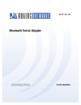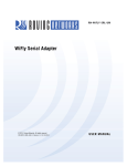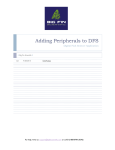
1
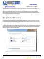
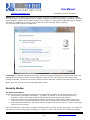
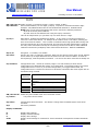
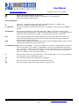
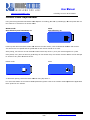
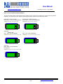
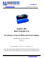
User Manual
www.rovingnetworks.com
rn-fireflubp-um Version 1.0 3/9/2010
FIREFLY BP
RN
RN-270 & RN-274
AAA Battery Powered Bluetooth Serial Adapter
Install Guide and User Manual
Version 4.77
Sept 5th 2009
Copyright © 2009 Roving Networks, Inc. All Rights Reserved.
The contents of this document can be changed by Roving networks without prior notice and do not
constitute any binding undertakings from Roving networks. Roving Networks is not responsible under any
circumstances for direct, indirect, unexpected or consequent damage that is caused by this document.
809 University Avenue • Los Gatos, CA 95032 • Tel (408) 395-6539 • [email protected]
~1~
User Manual
www.rovingnetworks.com
rn-fireflubp-um Version 1.0 3/9/2010
Overview
The FireFly BP is a battery powered Bluetooth to serial RS232 (RN-270) or RS422 (RN-274) adapter. Powered by
two AAA batteries or and external source, the adapter can be used with NiMH batteries and recharged from
external power plug or pin 9 on the DB9 connector. The FireFly BP will run for 10-14 hours while connected over
Bluetooth on a fully charged set of batteries.
Like the FireFly (RN-240) serial adapter the FireFly BP is a Bluetooth cable replacement solution for connecting
external devices up to 100 meters away to a PC or PDA.
The FireFly BP can also be used in cable replacement mode where two Roving Networks Bluetooth devices are
paired using the configuration switches. The USB to Bluetooth (RN-USB-X) has pairing switches and can be used
with the FireFly BP to create a wireless connection to a PC without using the PC’s Bluetooth stack.
When configured in master mode the FireFly BP will connect over Bluetooth to a remote client or Bluetooth access
point on power up, data or by command.
Powering on the FireFly
The red button on the top of the FireFly is the ON/OFF switch. The FireFly must have batteries to function, even if
the device is powered externally.
Warning: Do NOT use alkaline batteries when connecting the external power plug or applying power
on pin 9 of the DB9 connector.
To turn ON the FireFLy press down the red button for 1 second until the green and blue LEDS start flashing, then
release it. After a moment the blue LED will go off and the green LED will be flashing to indicate the device is ON
and not connected.
To turn OFF the FireFly press down on the red button for 1 second until the green and blue LEDS start flashing,
then release it. All the LEDs will go off.
By default the FireFly BP automatically shuts itself off if not connected over Bluetooth for more than 3 minutes =
180 seconds. The auto shut off duration is controlled by the sleep timer which is programmable with the "S+”
command.
For example:
S+,600” Sets the timer to 10 minutes.
Use the "O" command to display the current settings of the sleep timer.
Status LEDs
The blue LED indicates the status of the Bluetooth connection and when the device is in configuration mode.
MODE
GREEN LED BLINK
In Configuration mode
Boot up, Remote Configurable
Discoverable/Idle
Connected
Fast, 10 x per second
2 times per second
1 time per second
On Solid
809 University Avenue • Los Gatos, CA 95032 • Tel (408) 395-6539 • [email protected]
~2~
User Manual
www.rovingnetworks.com
rn-fireflubp-um Version 1.0 3/9/2010
The yellow LED blinks when data is sent or received on the serial inteface. This does not indicate that the data
was sent over the Bluetooth connection. If the yellow LED is not flashing when your device is sending data to the
serial port, you likely have the connection or flow control incorrectly set.
The blue LED indicates battery status and will blink slowly when the batteries are low except when charging.
When charging the blue LED remains off. If the unit is powered on while the batteries are charging the blue LED
will come on when the batteries are fully charged
The red LED indicates external power is present at either the power plug of DB9 connector.
Making a Bluetooth Connection
In most cases the FireFly BP acts as a slave (default mode) and the PC is the master. Connecting to the FireFly
BP is done through the Bluetooth device manager which has a different look and feel in Window CE, 2K, XP and
Vista Regardless of the PC operating system, the process is essentially the same: Discovery, Pairing, Connecting.
These processes are described below for a Windows 7 machine.
Discovery: The FireFlyBP must be discoverable by simply turning it on. The Green LED should be blinking. On
your PC open the Bluetooth device manager and click on “add” a new device. The Bluetooth device manager will
display a list of all the Bluetooth devices that are discoverable. The FireFly will be displayed as “FireFlyBP-XXXX”
where XXX is the last 4 digits of the MAC address.
809 University Avenue • Los Gatos, CA 95032 • Tel (408) 395-6539 • [email protected]
~3~
User Manual
www.rovingnetworks.com
rn-fireflubp-um Version 1.0 3/9/2010
Pairing: Next you must pair with the device by double clicking on FireFlyBP-XXXX in the list. Enter the default
pin code of 1234. Once the Bluetooth device manager completes you will see a message to the effect, “Bluetooth
device installed on COMX” where COMX is unique to your machine. In some cases the Bluetooth device manager
will create two COM ports, in this case you only want to use the COM port labeled “outgoing”
You only need to pair with the FireFlyBP once.
Connecting: To establish a Bluetooth connection, open up the COM port assigned to the device from either your
application or a terminal emulator. Once the COM port is open you will notice the green LED switches from
blinking to solid ON. The device will remain connected until the COM port is closed or the FireFly BP is turned off.
NOTE: Only one client can connect to the FireFly BP at a time.
Security Modes
Pin Codes and Link Keys
If either the local or the remote Bluetooth device has authentication enabled, the following process occurs.
1. The first time a connection is attempted, a “passkey” is required. This is a series of numbers or
characters. (1234 is the default for the Roving Networks Bluetooth devices and modules)
2. Once this is entered, the remote Bluetooth device and local device compare their passkeys and if they
match, a link key is generated, and stored. Usually, but not always this is stored by the remote device.
3. Upon subsequent connections, the devices will first compare link keys and if they are correct, no pin code
will have to be re-entered.
If the remote device is a PC or PDA, a prompt is generally made to the user to enter this pincode. To remove the
stored link key on the remote device, generally you “unpair” or remove the device from the Bluetooth manager.
809 University Avenue • Los Gatos, CA 95032 • Tel (408) 395-6539 • [email protected]
~4~
User Manual
www.rovingnetworks.com
rn-fireflubp-um Version 1.0 3/9/2010
You can change the Pin Code to remove the link key on the FireFlyBP. This will force a new Pin Code exchange
process to occur upon subsequent connection attempts.
Encryption
By default the encryption is OFF on the FireFly BP. With that said Bluetooth is very difficult to intercept because
the transmission are frequency jumping across 79 channels. The ordering is pseudo random with the devices
agreeing on a seed during the pairing process. Data encryption can enabled using the SE,1 command. SE,0
disables encryption.
Configuration Switches
The configuration switches on the top of the FireFly BP are small. You will need a paper clip or small screw driver
to change them. Hold the devices with the DB9 connector facing to the right, the switches are numbered one to
four from bottom
ttom to top and the off position is towards the DB9 connector.
1 – RESTORE FACTORY DEFAULTS
Set this switch ON, power up unit, and toggle the switch from ON to OFF 3 times to return the unit to factory
settings.
2 - AUTO DISCOVERY
In slave mode, sets a special class of device that is used the master to auto connect. If Switch 3 also ON, the
device performs a search, stores, and connects to a remote slave which has this switch 2 set.
3 - AUTO MASTER
Device acts as Bluetooth master, auto-connects
connects to a stored remote address. First set the Bluetooth address of
the slave device using the SR command or through instant cable replacement settings.
4 - DEFAULT BAUD RATE
OFF = 115K will be overridden by software baud rate configuration commands, ON = 9600 ignores any software
configuration
809 University Avenue • Los Gatos, CA 95032 • Tel (408) 395-6539 • [email protected]
~5~
User Manual
www.rovingnetworks.com
rn-fireflubp-um Version 1.0 3/9/2010
Batteries and Charging
Only use NiMH rechargeable batteries when externally powering the FirFly BP. Applying power with
alkaline batteries will damage the device and could cause a fire hazard.
The red LED comes on SOLID when external power is present. When turning on the firefly a BLINKING blue LED
indicates low battery. Battery life between charges depends on use. With typical usage you should get at least 10
hours of continuous use between charges. Enabling sniff mode can extend the battery life.
External power can be applied from either the 5 VDC plug or pin 9 on the DB9 connector. The power plug is
center pin positive, outer cylinder GND. Input MUST be 5 VDC for proper battery charging. Higher voltages can
permanently damage the charger and battery.
In configuration mode the bat command will return the current battery voltage. Note that with rechargeable NiMh
batteries the voltage will remain relatively unchanged just until they go dead.
RN-270 Battery Life Table (Tested using rechargeable 1000mAHr AAA batteries)
Sniff Time (milli sec)
Sniff mode
0
100
200
400
Battery Life (with
status LEDs)
8 hrs, 20 mins
17 hrs
17 hrs, 30 mins
18 hrs
Battery Life (without
status LEDs)
10 hrs
19 hrs, 30 mins
20 hrs
20 hrs, 30 mins
Please Note: The above readings are approximate and are to be used as a reference only. Battery life varies
depending on the type of batteries used and usage profiles. New rechargeable batteries tend to have a longer
battery life than older rechargeable batteries
Operating Modes
The operating modes for the FireFly BP are set using the “SM” command when in command mode. The possible
operating modes are:
Slave (SM,1<CR>) Default mode, whereby other Bluetooth devices can discover and connect to the
FireFly BP
Master (SM,1<CR>) In this mode, the FireFly BP makes connections when a Connect Command “C”, is
received. This command can also contain the Bluetooth address of the remote device. If no device is
specified, then the store remote address is used. The connection can be broken if the special break
character or string is sent (use the SO command to set the break character) This is a low speed
connect mode.
Trigger (SM,2<CR In this mode, the FireFly BP makes connections automatically when a character is
received on the serial port. The connection will continue as long as characters are received on either end.
There is a configurable timeout (which is set using the ST command) which will cause a disconnect after
XX (from 1 to 254) seconds of inactivity. This is a low speed connect mode.
Auto Master (SM,3<CR>) In this mode, the FireFly BP makes connections automatically on power up,
and re-connects when connection is lost. This mode can also be enabled by setting Dip Switch #2. This
is the high speed connect mode, and cannot be broken by software break characters.
In all master modes the device will not be discoverable or allow configuration remotely over Bluetooth.
809 University Avenue • Los Gatos, CA 95032 • Tel (408) 395-6539 • [email protected]
~6~
User Manual
www.rovingnetworks.com
rn-fireflubp-um Version 1.0 3/9/2010
Low Speed Connect Mode: in Manual and Trigger mode, the FireFly BP is making a LOW speed connection,
that is, data is being processed by the FireFly BP before being sent over the air. Because the FireFly BP is looking
for break or config character(s), the latency will increase and data rate will be decreased in these modes. Thus it
is recommended that for data rates above 57.6K these modes not be used.
Low Power Mode
Reducing power while connected
Lower power while connected can be achieved by setting the sniff mode. By default, Sniff mode is disabled, and
the radio is active continuously when connected (about 25-30ma). In Sniff mode, the radio wakes up at specific
intervals, and sleeps in very low power mode (around 2ma) otherwise. The power savings can be quite
dramatic.
To enable it, use the “SW,<hex word>“ command.
Example interval timers:
0x0020 = 20ms. (32 decimal * .625 = 20).
0x0050 = 50ms, 0x00A0 = 100ms, 0x0190 = ¼ second, 0x0320 = ½ second,
(Maximum) 20 seconds = 0x7FFF
0x0640 = 1 second,
Sniff mode only pertains to an active connection. When a connection is made, both master and slave must
support Sniff mode, and agree to the Sniff window, otherwise the radio will stay in full active on mode.
Automatically turning off the FireFly when not connected
By default the FireFly BP automatically shuts itself off if not connected over Bluetooth for more than 3 minutes =
180 seconds. The auto shut off duration is controlled by the sleep timer which is programmable with the "S+”
command.
For example:
S+,600” Sets the timer to 10 minutes.
Use the "O" command to display the current settings of the sleep timer.
Reducing power while not connected
Low power connect mode disables the Bluetooth radio and LED timers while not connected. When set, the module
will cycle between active (discoverable and connectable) and low power deep sleep. This can save considerable
power when the module is waiting for long periods of time without a connection. The trade off is additional
latency when connecting or pairing.
Lower power connect mode is turned on using the command
S|,<value>
Value is a four digit number made up of two one byte intervals. The first interval is the ON period and the second
the OFF period. Both are in seconds. The maximum value is 20 seconds for either of the periods. Default is 0000
always actively waiting for a connection.
809 University Avenue • Los Gatos, CA 95032 • Tel (408) 395-6539 • [email protected]
~7~
User Manual
www.rovingnetworks.com
rn-fireflubp-um Version 1.0 3/9/2010
Serial Connector
tor Specification
DB9 connector Pin Out
Pin
RN-270M
Male DB9
RN
RN-270F
Female DB9
RN-274M
Male DB9
1
2
3
4
5
6
7
8
9
NC
RXD
TXD
NC
GND
NC
RTS
CTS
4-12VDC
NC
TXD
RXD
NC
GND
NC
CTS
RTS
4-12VDC
12VDC
NC
NC
RXDTXD+
GND
+5 VDC (input)
RXD+
TXDNC
NOTE: The RS422 interface uses the MAX490 transceiver.
range of 4.75 to 5.25 VDC.
This device is designed to operate with input voltage
RXD+ and TXD+ each have a 4.7K pull up to 5VDC.
RXD- and TXD- each have a 4.7K pull down to GND.
NOTE: The RS232 interface uses the SIPEX SP3232ECA chip with capacitor switch to generate the + and – signals
and thus is not driving the full RS232 voltages. Devices stealing power from the RS232 pins may not have enough
voltage.
Device Configuration
The default configuration
ration for the FireFly BP is
Bluetooth slave mode
Bluetooth pin code 1234
Serial port 115K baudrate, 8 bits, NP, 1 stop bit
Serial port flow control disabled
Low power mode off
Configuration is done by putting the FireFly BP into command mode and sen
sending
ding ASCII commands. This can be
done over the serial port or over the Bluetooth link.
Once you change the configuration parameters, they persist until changed or a factory reset is performed.
Local configuration over the serial port
Connect the FireFly
y BP to the serial port your computer. You may need a null
null-modem
modem cable (DB9 pins 2 and 3
swapped) if you have a RN-270M
270M or a straight cable if you have a RN
RN-270F.
270F. If your computer does not have a
serial port you can use a USB serial cable such as the RN
RN-USB-SERIAL to connect the FireFly BP to your
computer.
The RN-274
274 will require a RS422 to RS232 converter or RS422 to USB cable to connect the FireFly BP to your
computer.
809 University Avenue • Los Gatos, CA 95032 • Tel (408) 395-6539 • [email protected]
~8~
User Manual
www.rovingnetworks.com
rn-fireflubp-um Version 1.0 3/9/2010
With the FireFLy BP connected and powered on, start your favorite terminal emulator and open the COM port that
the serial interface or serial USB is connected to. (A free terminal emulator, Teraterm for the PC is available at
www.rovingnetworks.com/support/teraterm.zip)
The communication settings of the terminal emulator should match the default serial port settings of the FireFly
BP of 115,200Kbps, 8 bits, No Parity, 1 stop bit.
Remote Configuration over Bluetooth
You must first pair the Bluetooth device with your computer. Click on the “Bluetooth devices” icon in the system
tray at the bottom right of your computer. Select “Add a Bluetooth device”
NOTE:
Remote configuration can only occur if the bootup configuration timer (default 60 seconds) has not
expired. This timer is set to 0 (remote config disabled) for master mode, and auto-connect slave
mode, so that data can immediately flow between the 2 devices in cable replacement fashion.
You must first pair the Bluetooth device with your computer. Click on the “Bluetooth devices” icon in the system
tray at the bottom right of your computer. Select “Add a Bluetooth device”
Getting into command mode
Launch TeraTerm and make sure that the default settings are selected (115,200Kbps, 8 bits, No Parity, 1 stop
bit). You can change these settings by clicking on Setup Serial Port from within TeraTerm.
Type $$$ into the terminal emulator (3 dollar signs). You should see CMD returned to you. If you see CMD you
know that your connection and terminal settings are correct.
Entering a valid command will return an AOK, invalid syntax returns ERR, and unrecognized commands will
return a ?. Type “h”<cr> to see a list of commands, and “d”<cr> to see a summary of current settings.
To return to data mode, type
“---“ ( 3 minus signs) <cr>, or reset the device and connect again.
809 University Avenue • Los Gatos, CA 95032 • Tel (408) 395-6539 • [email protected]
~9~
User Manual
www.rovingnetworks.com
rn-fireflubp-um Version 1.0 3/9/2010
Command Summary
All configuration information is stored in flash memory. The “set” command modifies the flash memory however
the Bluetooth module only reads the configuration from flash when powering up or after a reboot.
Some examples of common configuration commands:
SU,9600
SN,myname
SA,1
SP,secret
SF,1
R,1
sets Uart Baudrate to 9600
sets Bluetooth name to “myname”
enables secure authentication
sets security pincode to “secret”
restores all values to factory defaults
reboots the module
Set commands
S7,<1,0>
SL,<E,O,N>
SU,<rate>
7 bit data mode. 1 to enable, 0 to disable. (setting can be seen with the “d” command).
Set UART parity.
Can be any of, Even, Odd, or None. Only the first character is needed and
must be capital.
Baudrate, {1200, 2400, 4800, 9600, 19.2, 28.8, 38.4, 57.6, 115K, 230K, 460K, 921K },
only the first 2 characters are needed.
SN,<name>
SS,<text>
Name of the device, 20 characters maximum. Example: “SN,MyDevice”
Service Name (1 to 20 characters ).
S-,<name>
Serialized Friendly Name of the device, 15 characters maximum. This command will
automatically append the last 2 bytes of the BT MAC address to the name. Example: S,MyDevice will set the name to “MyDevice-ABCD”
Service Class (four hex values, 11 bits used) this is used with Device Class command below
to create the 24 bit Class of Device number.
Device Class (four hex values, major and minor in a 16 bit word, used with service class
above)
To set the Class of Device (COD) to 0x1F0123 use the commands
SC,<hex word>
SD,<hex word>
809 University Avenue • Los Gatos, CA 95032 • Tel (408) 395-6539 • [email protected]
~ 10 ~
User Manual
www.rovingnetworks.com
rn-fireflubp-um Version 1.0 3/9/2010
SC,001F
SD,0123
SM,<5,4,3,2,1,0> Mode (0=slave, 1=master,2=trigger, 3=auto, 4=DTR, 5=ANY)
SR,<address>
Store remote address, 12 hex digits, (6 bytes) no spaces or characters between digits
Example: SR,00A053112233 sets the remote Bluetooth address to 00A053112233
NOTE there are two special characters that can be used for the address parameter:
SR,Z will erase any stored address.
SR,I will write the last address seen using the inquiry command.
This can be helpful when you just have only one other device in range.
S?,<0,1>
Role Switch. Enables and disables Role Switch. If set, when an incoming connection is
occurs to a slave mode device, an attempt will be made to force a role switch, allowing the
slave to become the master. This is useful in situations where high speed data is being sent
from the local device up to the remote host, and can result in better performance. However
this may create a situation whereby the connecting host will not be able to make additional
outbound connections (multipoint) while connected to this device. Default is DISABLED.
SE,<1,0>
SP,<text>
Encryption 1 to enable, 0 to disable.
Security pin code, 20 character maximum. Each time the device success pairs, the BT address
will be saved. Up to eight addresses can be stored on a first in first out bases. To erase all
stored pairings, reset the passkey command. You can use the same value that is already set.
ST,<number>
Configuration timer, number of seconds (range= 0 to 255 decimal) to allow remote
configuration over Bluetooth after power up in Slave Mode. In all Master modes, the remote
configuration timer is set to 0 (no remote configuration). In Trigger Master Mode, the
configuration timer is used as an idle timer to break the connection after time expires with no
characters being received.
VALUE
(decimal)
0
1-252
253
254
255
DESCRIPTION
No remote config, No local config when
connected
Time in seconds from power up to allow
config
Continous config LOCAL only
Contiuous config, REMOTE only
Continous config, both LOCAL and REMOTE
SW,<hex word> Enable low power SNIFF mode. See Low Power section
S|,<value>
Low power connect mode.
S$,<char>
SF,1
Configuration detect character. This allows a change from the default $$$ to some other
character.
Set Factory Defaults.
Display commands:
D
E
O
G<X>
Display
Display
Display
Display
above.
basic settings.
extended settings
other settings
stored settings for command X. These commands correspond to the SET commands
809 University Avenue • Los Gatos, CA 95032 • Tel (408) 395-6539 • [email protected]
~ 11 ~
User Manual
www.rovingnetworks.com
GB
GK
V
rn-fireflubp-um Version 1.0 3/9/2010
Returns the Bluetooth Address of the device.
Returns the current connection status: 1=connected, 0 = not connected.
Return the software release version
Action Commands
+
C
C,<address>
Local echo. Toggle local echo of RX chars in command mode only. (default is off ).
Attempt to connect to the REMOTE stored address.
Connect to the address specified in hex format. The address is also stored as the REMOTE
address.
CF<address>
Connect and immediately go into FAST data mode. NOTE: you will not be able to enter
command mode while connected. PIO6 can still be used to disconnect. Thus PIO6 should be
held HIGH before sending this command, as lowering PIO6 will cause a disconnect.
CFI
Connect and immediately go into FAST data mode using the LAST address found from the
Inquiry command. NOTE: you will not be able to enter command mode while connected.
PIO6 can still be used to disconnect.
Connect and immediately go into FAST data mode using the REMOTE address. Similar to the C
command but bypasses the configuration timer.
CFR
CT<address>,<timer> Connect with TIMER. The device will NOT use or store the remote address, rather will
make a connection to the <address> (REQUIRED). The device will automatically disconnect
after 7 seconds if no data is seen from UART or BT. An optional timer value can be entered to
change the timer. This value is in ¼ seconds. So for a 30 second timer, use 120 as the
value. The maximum value is 255 (64 seconds)
K,
F,1
Kill (disconnect) from the current connection. The characters KILL<cr><lf> will be echoed to
the local UART once the connection is broken.
Go into fast data mode, ends configuration immediately.
H
R,1
Help, will print out a list of commands and their basic syntax
Forces a complete reboot of the device (similar to a power cycle
809 University Avenue • Los Gatos, CA 95032 • Tel (408) 395-6539 • [email protected]
~ 12 ~
User Manual
www.rovingnetworks.com
rn-fireflubp-um Version 1.0 3/9/2010
Instant Cable Replacement
Using two Roving Networks Bluetooth serial adapters or FirePlug (RN
(RN-USB-X)
X) USB dongle, with the power OFF set
the switches on each device as shown below.
Master mode
Auto discovery and auto Master on
on
Slave
Auto discovery on
off
on
4
3
2
1
off
4
3
2
1
Power up both devices and the master will discover the slave device, store its Bluetooth address and connect.
The devices are now paired and the green LED on each device should be on solid.
After pairing, set switch 2 on both devices to OFF so that they don’t try to re
re-pair
pair each time power is cycled.
Once paired, every time the devices get in range of one another they will connect and the master will
wil not attempt
to connect to any other Bluetooth device.
Master mode
Slave
To break this pairing restore the factor defaults using dip switch 1.
For more information on the instant cable replacement, please refer to the ‘Instant Cable Replacement Application
Note” posted on our website.
809 University Avenue • Los Gatos, CA 95032 • Tel (408) 395-6539 • [email protected]
~ 13 ~
User Manual
www.rovingnetworks.com
rn-fireflubp-um Version 1.0 3/9/2010
Flow control and Null modem Jumpers
The Firefly 270M and RN-270F RS232 serial interface can be configured to enable flow control and null modem
signaling. On older units, this requires removing the plastic enclosure to access the jumpers.
Male DB9 (Default Config)
DTE 3 Wire - Flow control DISABLED
Jumpers 1<>2, 3<>4, 9<>10
1
3
5
7
9
2
4
6
8
10
Male DB9
Female DB9
DTE - Flow control ENABLED
Jumpers 1<>2, 3<>4, 5<>6, 7<>8
1
3
5
7
9
Female DB9 (Default Config)
DTE 3 Wire - Flow control DISABLED
Jumpers 1<>3, 2<>4, 9<>10
2
4
6
8
10
1
3
5
7
9
2
4
6
8
10
DTE - Flow control ENABLED
Jumpers 1<>3, 2<>4, 5<>6, 7<>8
1
3
5
7
9
2
4
6
8
10
Male DB9
DCE - Flow control ENABLED
Null Modem
Jumpers 1<>3, 2<>4, 5<>6, 7<>8
1
3
5
7
9
2
4
6
8
10
809 University Avenue • Los Gatos, CA 95032 • Tel (408) 395-6539 • [email protected]
~ 14 ~