1
RN Commands Version 4.25,
11/1/2007
Page 13 of 25
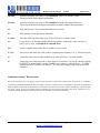
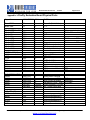
COMMANDS to MANIPULATE GPIO
CMD
@
&
%
^
*
VALUE
<hexword>
<hexword>
<hexword>
<hexword>
<hexword>
DESCRIPTION
Set direction bits for GPIO
Set values for GPIO
Store powerup direction bits for GPIO
Store powerup values for GPIO
Set values for PIO8,9,10,11
The GPIO command interface uses combination
of 2bytes, a mask, and value, packed into a hex
word for each command. The first byte, the
mask, determines which GPIO are to be
affected, and the second byte is the value to set.
15 --------- 8 7 -------- 0
<hexword> = MASK[7...0] VALUE[7..0]
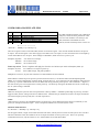
There are 2 registers used to control the GPIO, the first is a direction register. This controls whether the GPIO is an input or
an output. The second register is the value to apply to the GPIO if set to an output, or is the value of the built-in weak pull-up
resistor if the GPIO is set to an input. These settings are immediate, and do not survive a power cycle.
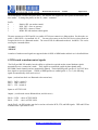
Examples: S@,8080
S&,8080
S&,8000
sets GPIO-7 to an output
drives GPIO-7 high
drives GPIO-7 low
Power-up values: These 2 registers will apply the direction and values upon each subsequent power-up:
Examples: S%,0101 sets GPIO-0 to an output on power-up
S^,0303
drives GPIO-0 high, and pulls up GPIO-1.
Multiple bits can be set, any bits with a mask of 0 are left unaffected for the command.
Some GPIO are checked at power-up time to perform certain functions, so care must be taken when manipulating them.
GPIO3, 6, are used to automatically set master mode, and auto discovery. If it is desired to use these GPIO for other purposes
at power-up, a special command mu st be used to disable their being sensed at power-up time. This command is “SQ,4<cr>”
this will set a flag in a stored register that is read at power-up. The Power-up settings for the GPIO can also be viewed using
the “O” (other settings) command.
WARNING:
GPIO-4 is used by the system to reset stored parameters to factory defaults. If GPIO4 is pulled high on power-up, and then
toggled 3 times, all user settings will return to default values. Therefore this pin should not be used as an output, and should
not be driven high at power-up time (first 1 second of operation).
NOTE:
GPIO2 and 5 are driven by the embedded software as outputs, they can be disabled using the direction command, (to save
power, for example) and used as inputs. If set to outputs the software will override any user values.
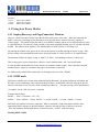
SETTING GPIO 8-9-10-11
S*,<hexword> = MASK[11..8] VALUE[11..8]
For the upper 4 GPIO, a single word controls the mask and values, and only the lower 4 bits of each byte are used. The first
time this command is used, all 4 GPIO are driven as outputs and remain so until a power cycle. There is no powerup
command for these bits, only the interactive one. Some modules do not offer these GPIO.
809 University Avenue
• Los Gatos, CA 95032 • 1-(408) 395-6539 • [email protected]
www.rovingnetworks.com