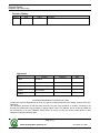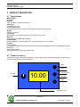
1
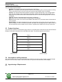
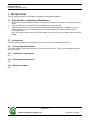
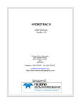
REMOTE DISPLAY
HARDWARE HIGH LEVEL DESIGN
Version: 0.2
Status: Draft
Report No.: OHSI/IR12345.1
Odom Hydrographic Systems, Inc.
1450 Seaboard Avenue
Baton Rouge, Louisiana
USA
70810-6261
Telephone: (225) 769-3051
Fax: (225) 766-5122
[email protected]
http://www.odomhydrographic.com
Number of pages: 10
Date: November 19, 2004
Remote Display
Hardware High Level Design
Revision History
Version
1.0
Date
11-19-2004
Author
C. Myer
Remarks
Initial version – draft
Approved
By:
Function
R. Byrd
President
S. Apsey
Vice-president
C. Myer
Sr. Technical Engineer
M. Wilis
Sr. Architect
Signature
Date
<Author>
© ODOM HYDROGRAPHIC SYSTEMS, INC. 2004
All rights are reserved. Reproduction in whole or in part is prohibited without the prior written consent of the copyright owner.
The information presented in this document does not form part of any quotation or contract, is believed to be
accurate and reliable and may be subject to change without notice. The publisher will not accept any liability for
any consequence of its use. Publication thereof does not convey nor imply any license under patent- or other
industrial or intellectual property rights.
Page 2 of 2
Odom Hydrographic Systems, Inc.
November 19, 2004
Remote Display
Hardware High Level Design
Page 3 of 3
Odom Hydrographic Systems, Inc.
November 19, 2004
Remote Display
Hardware High Level Design
CONTENTS
1
Introduction.......................................................................................................................................................5
1.1
1.2
1.3
1.4
2
PRODUCT description .....................................................................................................................................6
2.1
2.2
2.3
2.4
2.5
3
Purpose ........................................................................................................................................................5
Scope ...........................................................................................................................................................5
Glossary .......................................................................................................................................................5
References ...................................................................................................................................................5
Specifications ...............................................................................................................................................6
Product Functions ........................................................................................................................................6
Product Interfaces ........................................................................................................................................7
Assumptions and Dependencies .................................................................................................................7
Apportioning of Requirements......................................................................................................................7
Installation.........................................................................................................................................................8
3.1
Echo Sounder configurations / Modifications...............................................................................................8
3.2
Connections .................................................................................................................................................8
3.2.1
Powering Up the Equipment .................................................................................................................8
3.2.2
Component configurations ....................................................................................................................8
3.2.3
Performance Requirements ..................................................................................................................8
3.2.4
Design constraints ................................................................................................................................8
3.2.5
Bill of Materials......................................................................................................................................9
3.3
Quality issues ...............................................................................................................................................9
3.4
Troubleshooting ...........................................................................................................................................9
Page 4 of 4
Odom Hydrographic Systems, Inc.
November 19, 2004
Remote Display
Hardware High Level Design
1 INTRODUCTION
The Remote Display is a single 4 x 20 LCD used to display depth information from the Echotrac series of echo
sounders. The depth information is displayed in the same units as the echo sounder, where one decimal place
represents feet and two decimal places represent meters. It is contained in a metal housing installed on a swivel
mounting bracket. There is one DB9 connector mounted on the back, which supplies power and the serial data
from the sounder.
1.1
Purpose
The purpose of this document is to describe the features and operation of the Echotrac MKIII or the Deso 30
Remote Display.
1.2
Scope
The content of this document is focused on the user.
1.3
Glossary
N/A
1.4
References
N/A
Page 5 of 5
Odom Hydrographic Systems, Inc.
November 19, 2004
Remote Display
Hardware High Level Design
2 PRODUCT DESCRIPTION
2.1
Specifications
Model Number
RDU-2004
Display
4x20 Dot matrix Character LCD Module.
Resolution
0.01 Meters, 0.1 Feet
Power Requirements
24V supplied by the echo sounder through the standard serial cable (pin #8)
Weight
0.765 kg (1.6875 lb.)
Dimensions
Width 5.08cm (2”) X Length 22.86cm (9”) X Height 14.35cm (5.65”)
Mounting
Swivel bracket for a Bulkhead installation
Ports/Interface
RS422 (depth data; operating power 24V; connect to COM2 of the echo sounder)
Features
LCD Brightness
Channel Select (dependent on mode of echo sounder: Single High Bathymetry, Single Low Bathymetry, Dual
Bathymetry)
Alarm on/off (audible)
Mark (Used to fix mark the echo sounder chart)
2.2
Product Functions
This product is used to give the boat operator to remote view the echo sounder’s depth data. The following is a
picture representing the unit and its functions.
Mark
High Led
Contrast
10.00
Channel Select
Low Led
Alarm
Depth (ft of mt)
Page 6 of 6
Odom Hydrographic Systems, Inc.
November 19, 2004
Remote Display
Hardware High Level Design
The unit functions work as follows:
- Contrast: The contrast knob controls the brightness of the Display.
- Mark: The mark button allows the operator to mark the echo sounder printer, when the printer is running.
This can be used to mark an event of some kind such as a M.O.B marker (man over board).
- Channel: The channel select button allows the operator to select between Dual, Low, and High depths
when the echo sounder is set in dual frequency operation. Please note that if the echo sounder is in a
single frequency mode that the channel select button will have no effect and the appropriate Led will be
illuminated.
- Low Led: This led is illuminated when low frequency is displayed.
- High Led: This led is illuminated when the high frequency is displayed.
- Alarm: When the alarm is on, the led in the middle of the button is on, the internal alarm will buzz when a
echo is missed.
- Depth Display: The depth is displayed in the same units that the echo sounder. If there is one decimal
place, the depth is in feet. If no decimal is present, the depth is in feet and greater then 1000ft. If there are
two decimal places, then the depth units are meters. At greater then 1000mt, there is only one decimal.
2.3
Product Interfaces
The connection, between Communications port number 2 on the back panel of the Echo sounder and the Remote
Display, is made with a standard off the shelf DB9 serial cable. The pertinent signals are as follows.
2
TX2-A
2
3
RX2-A
3
5
GND
5
6
TX2-B
6
7
RX2-B
7
8
+24V
8
Echo Sounder
2.4
Remote Display
Assumptions and Dependencies
Set communication port 2 to on and set the baud rate to 9600 (on the echo sounder). Power is supplied through
this port so do not connect COM2, of the echo sounder, to any device other than the Remote Display.
2.5
Apportioning of Requirements
N/A
Page 7 of 7
Odom Hydrographic Systems, Inc.
November 19, 2004
Remote Display
Hardware High Level Design
3 INSTALLATION
The unit comes mounted on a swivel bracket, designed for a bulkhead installation.
3.1
Echo Sounder configurations / Modifications
1.
Set shunts for JP1 through JP4 to position 1-2 (current loop operation for COM2), on the 2416-0019-REVA
board.
Install a jumper wire on the back of 2416-0019-REVA between J3/6 and J2/6.
Install a jumper wire on the Communications Interface Board 2416-0010-REVA , between J1/6 (on the
back of the board) to Pin 8 of COM2 (on the front of the board). Run the jumper wire through the left
mounting hole of J1.
Note: The purpose of the jumper wires on both boards is to put 24V on pin 8 of COM2 to power the Remote
Display.
2.
3.
3.2
Connections
Connect the Remote Display to Communications Port 2 on the back of the MKIII or the Deso 30.
3.2.1
Powering Up the Equipment
The remote display will only power up when the echo sounder is turned on. It will only receive depth data when
the unit is running.
3.2.2
Component configurations
N/A
3.2.3
Performance Requirements
N/A
3.2.4
Design constraints
N/A
Page 8 of 8
Odom Hydrographic Systems, Inc.
November 19, 2004
Remote Display
Hardware High Level Design
3.2.5
Bill of Materials
#
1
2
3
4
4
5
QTY
10
1
2
2
3
1
PART REFERANCE #
C1,C3,C4,C5,C6,C7,C8,C9,C12,C13
C2
C10,C11
C14,C15
J1,J4,J6
J2
6
7
8
9
10
11
12
13
14
15
16
17
18
19
20
1
1
1
1
2
1
3
3
2
1
1
1
2
1
1
J3
J5
L1
Q1
R10,R1
R3
R4,R5,R6
R7,R8,R9
R12,R13
RV1
U1
U1
U2
J2
U3
21 1
3.3
U4
Value
0.1uf
4.7uf/16v
100uf
470uf
3PIN RIGHT ANGLE HEADER
16 PIN HEADER SINGLE ROW
HEADER
8 PIN RIGHT ANGLE HEADER
6 PIN RIGHT ANGLE HEADER
100UH POWER INDUCTOR
BCX5616
100 OHM
8.25K
10K
200 OHM
121 OHM
100 OHM POT
PIC16F877
PLCC44 SOCKET
MAX490
LCD Module
16MHZ 1/2 SIZE CRYSTAL
OSCILLATOR
PT5101C
SMT
SMT
SMT
THU
THU
THU
0805
1206
THU
THU
SMT
ODOM PART#
2710-0104-1000
2710-0475-1316
2710-0107-1100
1110-0477-1910
0610-0049-0000
0610-0053-0000
SMT
0610-0135-0000
0610-0040-0000
3111-0003-0000
1380-0010-0000
2712-1000-0001
2712-8251-0001
2712-1002-0001
2712-2000-0001
2712-1210-0001
1113-0100-0008
1400-0011-0000
0613-0011-0000
2710-0225-1325
0200-0014-0000
1011-0013-0000
SMT
1252-0004-0000
SMT
SMT
SMT
SMT
SMT
THU
SMT
THU
SMT
0805
0805
0805
0805
0805
S08
Quality issues
N/A
3.4
Troubleshooting
1. No display: Check to make sure the serial cable is properly attached to the back of the Remote
Display and connected to communication port 2 on the back of the echo sounder. If the cable is
connected correctly, open the echo sounder up and make sure the ribbon cable going to the COM
interface board is connected. Use a multimeter to verify that there is 24V between pin 8 and 5 of the
serial cable. If there is no voltage, check the fuse F1 on the top of the Com-ethernet board. You will
need to remove the cover to see the fuse. If none of this solves the problem, send the unit back. If,
however, 24V is present on the DB9, remove both sides of the Remote Display and verify the internal
connections. If everything is connected properly and the Remote Display still doesn’t power up, send
the unit back.
2. The Display comes on but remains in standby: This would indicate that no serial data is being sent
from the echo sounder. First, make sure that communication port 2 is set to ON in the echo sounder.
Please note that the echo sounder defaults to communication port 2 turned OFF. Make sure the baud
rate is set to 9600. If the remote still doesn’t display data, check the cable connection, and the jumper
configuration mentioned in the modifications notes 3.1. Remove both sides of the Remote and verify
the internal connections. If everything is connected properly and the unit still doesn’t power up, send
the unit back.
Page 9 of 9
Odom Hydrographic Systems, Inc.
November 19, 2004
Remote Display
Hardware High Level Design
Electrical diagram
Page 10 of 10
Odom Hydrographic Systems, Inc.
November 19, 2004