1
BugHunter Pro and the
VeriLogger Simulators
Copyright © 2011, SynaptiCAD Sales, Inc.
BugHunter Pro and the VeriLogger
Simulators
Copyright Copyright © 2011, SynaptiCAD Sales, Inc., version 14
All rights reserved. No parts of this work may be reproduced in any form or by any means - graphic, electronic, or
mechanical, including photocopying, recording, taping, or information storage and retrieval systems - without the
written permission of the publisher.
Products that are referred to in this document may be either trademarks and/or registered trademarks of the
respective owners. The publisher and the author make no claim to these trademarks.
While every precaution has been taken in the preparation of this document, the publisher and the author assume no
responsibility for errors or omissions, or for damages resulting from the use of information contained in this
document or from the use of programs and source code that may accompany it. In no event shall the publisher and
the author be liable for any loss of profit or any other commercial damage caused or alleged to have been caused
directly or indirectly by this document.
Printed: January 2011 in (whereever you are located)
BugHunter Pro and Verilog Simulators
BugHunter Pro, VeriLogger Extreme, VeriLogger Pro
Welcome to the BugHunter Pro, VeriLogger Extreme, and
VeriLogger Pro manual. This manual covers using the
BugHunter Pro graphical simulation and debugging interface.
This is the interface for both VeriLogger Extreme and
VeriLogger Pro and can also be used with most commercial
simulators.
BugHunter uses the SynaptiCAD graphical environment and
supports all major HDL simulators. It has the ability to launch
the simulator, provide single step debugging, unit-level test
bench generation, streaming of waveform data, project
management, and a hierarchy tree. The unit-level test bench
generation is unique in that it lets the user draw stimulus
waveforms and then generates the stimulus model and
wrapper code and launches the code. It is one of the fastest
ways to test a model and mak e sure that everything is
work ing correctly. The debugger also has exceptional support
for VCD waveform files.
With an integrated debugging environment you can
graphically build a project, launch a simulation, and view the
results in just a few minutes. The interface also manages the
test bench interface so that it is easy to create a set of
regression tests to run the design through
4
BugHunter Pro and the VeriLogger Simulators
Table of Contents
Foreword
0
7
Chapter 1: Getting Started with BugHunter
Step 1: Setup the ...................................................................................................................................
Simulator Path
7
Step 2: Setup the ...................................................................................................................................
Project Simulation Options
9
Step 3: Create a ...................................................................................................................................
Project
13
Step 4: Add Source
...................................................................................................................................
Files to the Project
15
Step 5: Draw a Test
...................................................................................................................................
Bench (optional)
16
Step 6: Build the ...................................................................................................................................
Project and Set the top
17
Step 7: Simulate ...................................................................................................................................
and Debug - General Overview
19
Step 8: Save the ...................................................................................................................................
Project, Code and Waveform Files
20
22
Chapter 2: Simulation and Debugging Functions
2.1 Build and Simulate
................................................................................................................................... 23
2.2 Watching Signal
...................................................................................................................................
and Component Waveforms
25
2.3 Breakpoints ................................................................................................................................... 27
2.4 Inspect Values
................................................................................................................................... 29
2.5 Find Drivers ................................................................................................................................... 32
2.6 Report Window
...................................................................................................................................
Error and Log file tabs
33
2.7 Command Console
...................................................................................................................................
for Interactive Debugging
34
2.8 Using Component
...................................................................................................................................
Libraries
40
2.9 Using VPI applications
...................................................................................................................................
to interface to the simulator
40
Chapter 3: Waveforms and Test Bench Generation
43
3.1 Stimulus and...................................................................................................................................
Results Diagram
43
3.2 Drawing Waveforms
...................................................................................................................................
for Stimulus Generation
46
3.3 Zooming, Scrolling,
...................................................................................................................................
Measuring, and Searching
48
3.4 Bit-Slicing a Watched
...................................................................................................................................
Signal
50
3.5 Waveform Comparisons
...................................................................................................................................
(Optional Features)
51
3.6 Generating and
...................................................................................................................................
Reading VCD and BTIM Files
54
Chapter 4: Editor Functions and Code Navigation
55
4.1 Opening, Saving,
...................................................................................................................................
and Creating New Source Code
55
4.2 Navigating Code
...................................................................................................................................
with Buttons and Report Tabs
57
4.3 Navigating Code
...................................................................................................................................
with the Project Window
59
4.4 Searching in ...................................................................................................................................
the Project Window
61
4.5 Editor and Report
...................................................................................................................................
Window Commands
62
4.6 The Editor/Report
...................................................................................................................................
Preferences Dialog
64
Copyright © 2011, SynaptiCAD Sales, Inc.
Contents
5
4.7 XEmacs Integration
...................................................................................................................................
and other External Editors
65
Chapter 5: VeriLogger Command Line Simulators
67
5.1 VeriLogger Extreme
...................................................................................................................................
tools: Simx and Simxloader
67
5.2 Preparing Verilog
...................................................................................................................................
Source files
69
5.3 Batch Files for
...................................................................................................................................
Command Line Simulators
69
5.4 Simx Commonly
...................................................................................................................................
used Command Line Options
70
5.5 Simx Simulation
...................................................................................................................................
Build Command Line Options
71
5.6 Simx Debug and
...................................................................................................................................
Logging Options
71
5.7 Simx Specify...................................................................................................................................
block and SDF Timing Options
72
5.8 Simx Override
...................................................................................................................................
Parameter Values Options
74
5.9 Simx Loading...................................................................................................................................
a PLI application Options
74
5.10 Race Detection
...................................................................................................................................
Options
75
5.11 Simx Miscellaneous
...................................................................................................................................
Options
76
5.12 Simx On-Event
...................................................................................................................................
and On-Detect Pulse Filtering
76
5.13 VeriLogger Pro
...................................................................................................................................
tools: Vlogcmd
76
5.14 Vlogcmd Simulator
...................................................................................................................................
Control Commands
80
5.15 Vlogcmd Predefined
...................................................................................................................................
Plus Options
80
Chapter 6: SDF, Encrypted Models, and SmartModels
82
6.1 Using a Standard
...................................................................................................................................
Delay File (SDF)
82
6.2 Verilog Protected
...................................................................................................................................
Envelopes (Encrypted Models)
83
6.3 SmartModels...................................................................................................................................
(Swift Models)
87
Chapter 7: Speed Tricks and Techniques
89
7.1 Dumping Simulation
...................................................................................................................................
Waveforms
89
7.2 What not to Watch
................................................................................................................................... 89
Chapter 8: Verilog2VHDL Translation
92
8.1 Graphical Interface
...................................................................................................................................
for Translation
92
8.2 Verilog2VHDL...................................................................................................................................
Translation Options
95
8.3 Compiling and
...................................................................................................................................
Simulating VHDL Output
97
8.4 Frequently Asked
...................................................................................................................................
Questions: Verilog2 VHDL
109
8.5 Recommended
...................................................................................................................................
Modeling Style Verilog
111
8.6 Verilog2VHDL
...................................................................................................................................
Known Issues
116
8.7 Verilog2VHDL
...................................................................................................................................
Release Notes
119
Chapter 9: VHDL2Verilog Translation
122
9.1 Graphical Interface
...................................................................................................................................
for Translation
122
9.2 VHDL2Verilog
...................................................................................................................................
Translation Options
126
9.3 Mapping VHDL
...................................................................................................................................
packages to file locations
128
Copyright © 2011, SynaptiCAD Sales, Inc.
5
6
BugHunter Pro and the VeriLogger Simulators
9.4 Mapping Functions
...................................................................................................................................
and Procedures
129
9.5 Translating Functions
...................................................................................................................................
and Procedures
131
9.6 D-FlipFlop Mapping
................................................................................................................................... 131
9.7 Importing (parts
...................................................................................................................................
of) Verilog files
133
9.8 Reserved Verilog
...................................................................................................................................
Keywords
133
9.9 Frequently Asked
...................................................................................................................................
questions VHDL2Verilog
134
9.10 Recommended
...................................................................................................................................
Modeling Style VHDL
136
9.11 VHDL2Verliog
...................................................................................................................................
Known Issues
142
9.12 VHDL2Verilog
...................................................................................................................................
Release Notes
144
Chapter 10: Schematic Viewing of Gate Level Designs
150
10.1 Gates-On-The-Fly
...................................................................................................................................
Install and License
150
10.2 Launching ...................................................................................................................................
the Schematic window
151
10.3 General GOF
...................................................................................................................................
Information
153
154
Appendix A: BugHunter System Tasks
init_syncad
................................................................................................................................... 155
btim_dumpfile ................................................................................................................................... 155
btim_closedumpfile
................................................................................................................................... 155
btim_AddDumpSignal
................................................................................................................................... 155
db_getcurrenttime
................................................................................................................................... 156
db_printinteractivescope
................................................................................................................................... 156
db_finish
................................................................................................................................... 157
db_addtimebreak
................................................................................................................................... 157
db_removetimebreak
................................................................................................................................... 157
db_enabletimebreak
................................................................................................................................... 157
db_disabletimebreak
................................................................................................................................... 158
db_getbasictype................................................................................................................................... 158
db_getvalue
................................................................................................................................... 158
db_printinternaltimeprecision
................................................................................................................................... 158
db_setinteractivescope
................................................................................................................................... 159
Enabling BTIM dump
...................................................................................................................................
commands in command-line simulator
159
Appendix B: Verilog2VHDL Translation Reference
160
Appendix C: VHDL2Verilog Translation Reference
171
Index
180
Copyright © 2011, SynaptiCAD Sales, Inc.
Chapter 1: Getting Started with BugHunter
7
Chapter 1: Getting Started with BugHunter
This chapter covers the basic steps involved in setting up BugHunter to work with your simulator and
how to create and debug a project. Each step is listed in the suggested order that you will want to
perform the functions.
Step 1: Setup the Simulator Path
7
Step 2: Setup the Simulator Options
Step 3: Create a Project
9
13
Step 4: Add Source Files to the Project
Step 5: Draw a Test Bench (optional)
15
16
Step 6: Build the Project and Set the top
Step 7: Simulate and Debug
17
19
Step 8: Save the Project, Code and Waveform Files
20
Step 1: Setup the Simulator Path
BugHunter Pro needs to know where your VHDL/Verilog simulator or C++ compiler is located. If you
are using VeriLogger Extreme or VeriLogger Pro you can skip this section because the simulator was
setup during installation unless you wish to run the 64-bit version of the simulator. BugHunter saves
the paths for each external simulator or compiler in the simulatorconfiguration.ini file each time the
program is closed.
Set the Path to the Simulator:
Choose the Options > Simulator / Compiler Settings menu option to open a dialog of that
name.
Copyright © 2011, SynaptiCAD Sales, Inc.
8
BugHunter Pro and the VeriLogger Simulators
In the Tools drop-down choose your
simulator or compiler. VeriLogger
Extreme will run either in 32bit mode
or 64bit mode depending on your OS
version (e.g. 32bit or 64bit OS). To
force 32bit operation on a 64bit
system, select VeriLogger Extreme
32.
The Compile Syncad Libraries button will be enabled for simulators that require it. This
button allows you to compile libraries needed by external simulators and compilers for
SynaptiCAD projects. This needs to be done one time before using a new simulator.
In the Simulator Path edit box, either type in the path name or use the browse button to
locate the path.
Copyright © 2011, SynaptiCAD Sales, Inc.
Chapter 1: Getting Started with BugHunter
9
Continue to setup the paths for each tool that you are interested in using. When you are done
click OK button to close the dialog.
Step 2: Setup the Project Simulation Options
Generally the default settings for each simulator will be sufficient to properly simulate a project, so
you can skip this section. However, if you you are moving projects back and forth between different
machines and simulators you may wish to create configuration templates for each machine. Also
you may wish to have different settings for different debug setups. The Project Simulation Properties
dialog determines the simulator run time options and which simulator to use for projects and
diagrams.
Open the Project Simulation Dialog:
Select the Project > Project Simulation Properties menu option to open the dialog
Global versus Project Settings
Select Settings Template to edit the default settings that are used by new projects. These
are stored in the INI file each time the program is closed. The Restore Default Templates
button is used to reset the INI file to the factory default settings for this dialog.
Select Global Diagram Settings to edit the options for how transactions are simulated
(simulated signals in a Diagram window). These are stored in the INI file.
Select Current Project Settings to edit the project settings for the current project. These
settings are stored in the Project HPJ file when you save the project.
Configurations:
If you are moving projects to different machines or if you want to have different settings for debugging
and releasing a project you may want to create a new configuration to store the different settings.
The Debug Configuration holds the default settings. If you need to define a new configuration:
Press the Add button to open the Add New Configuration dialog, that lets you specify a name
and the default configuration to copy the settings from.
Rename button lets you change the name of the current configuration.
Delete removes the current configuration.
Use the Configurations drop-down to choose which configuration you will be editing.
The General Tab:
The General tab contains simulation options that are standard across all of the simulators.
Copyright © 2011, SynaptiCAD Sales, Inc.
10
BugHunter Pro and the VeriLogger Simulators
Grab Top Level Signals
causes signals in the toplevel component to be
automatically added as
Watch signals in the
stimulus and results
diagram whenever the
project is rebuilt.
Capture and Show
Watched Signals enables
the display of waveform
results from a simulation
run.
Dump Watched Signals
generates a dump file for
any watched signals in the
diagram. The generated file
will named diagramName.
VCD.
Break at Time Zero is the equivalent of setting a breakpoint at time zero. This starts the
simulator and allows you to enter commands into the console window that will be executed
during simulation.
Clear Log File Before Compile clears the simulation log just prior to a new compilation
being performed. This log maintains compilation notes, as w ell as some simulation notes.
Note that in this dialog you can also change the name of this log (see Logfile below).
When the Auto Parse Project on Load box is checked, user source files are automatically
parsed and built when the project is loaded. The top-level component is the first component
that is not included by another for Verilog; it is the first entity/architecture pair parsed for
VHDL. This is mainly used by Actel Libero customers with WaveFormer Lite.
Generate Test Bench on Build Project automatically updates the test bench for changes to
timing diagrams. Turn this off if you want to temporarily change some of the generated source
code manually or to avoid updating the test bench on diagram changes.
Log File specifies the name of the log file that receives all the simulation results and
information. By default BugHunter uses simulation.log.
Verilog Tab:
The Verilog tab specifies the simulator and simulation options used for Verilog projects.
Simulator Type specifies the simulator.
Copyright © 2011, SynaptiCAD Sales, Inc.
Chapter 1: Getting Started with BugHunter
11
The
Simulator
Settings
button opens
the
Simulator /
Compiler
Settings
dialog where
you can edit
the simulator
paths.
Include Directories specifies the directories where BugHunter searches for included files.
The following is a Windows example (Unix users should use the / slashes):
C:\design\project;c:\design\library
The Library Directories box lists the path and directories where the program searches for
library files. BugHunter will try to match any undefined components with the names of the files
that have one of the file extensions listed in the Lib Extensions edit box. The simulator does
not look inside a file unless the undefined component name exactly matches a file name. The
simulator does not look at any files unless there are file extensions listed in the Lib
Extensions edit box. Note that this works even with compiled code simulators that don't
normally support the -y option. The following is a Windows example (Unix users should use
the / slashes):
C:\design\project;c:\design\library
The Lib Extensions box specifies the file name extension used when searching for library files
in the library directory. Each library extension should begin with the period character followed
by the extension name. Use a semicolon to separate multiple file extensions.
.v;.vo
The Delay Settings radio buttons determines which delay value is used in min:typ:max
expressions. These settings are output as either the +maxdelays, +mindelays, or
+typdelays command line simulator option.
Compile, Elaborator, and Simulator option edit boxes allow you to write additional
command line options that will be passed to the tool when it is run. Most simulators do not
support all three phases of command line options.
When the Generate Command File button is pushed, the text contained in the Simulator
Copyright © 2011, SynaptiCAD Sales, Inc.
12
BugHunter Pro and the VeriLogger Simulators
Options edit box along with the list of Verilog files specified in the Project window are written
to a Command File. This file can then be used with the Command Line version of your
simulator to run a simulation without the BugHunter GUI.
The Drive Events using PLI checkbox changes the way stimulus from the
StimulusAndResults diagram is sent to the simulator. By default, stimulus waveforms cause
Verilog stimulus code to be compiled into the simulation (see Section 3.2: Drawing Waveforms
for Stimulus Generation 46 ). But when this option is checked, stimulus is directly injected into
the simulation at runtime via a PLI application that reads from the btim timing diagram file.
This allows you to change the stimulus by editing the btim file without requiring a recompile of
your simulation. The disadvantage of this approach is that you cannot single step through the
stimulus, since it's injected via PLI.
The Make Parameters Watchable determines whether or not parameters will be included
with the automatic monitoring of ports and internal signals in the top-level component.
VHDL Tab:
The VHDL tab contains the simulation options and simulator used for VHDL projects.
Simulator Type determines the simulator.
The Simulator Settings button opens the Simulator / Compiler Settings dialog where you can
edit the simulator paths.
The VHDL 93 checkbox specifies that the project dialect for the generated files is VHDL 93.
The Compile, Elaborator, and Simulator options edit box allow you to write additional
command line options that will be passed to the tool when it is run. Most simulators do not
support all three phases of command line options.
The Additional File Extensions for Compile adds more types of files that will be considered
VHDL files.
TestBuilder Tab:
The TestBuilder tab contains the compiler options and compiler used for C++ projects.
Copyright © 2011, SynaptiCAD Sales, Inc.
Chapter 1: Getting Started with BugHunter
13
Compiler Type
specifies the C++
compiler.
The Compiler
Settings button
opens the
Simulator /
Compiler
Settings dialog
where you can
review and edit
the compiler
paths.
The Compile,
Linker, and Run
Time options
edit box allow
you to write
additional
command line
options that will
be passed to the
tool when it is
run.
Step 3: Create a Project
BugHunter Pro uses a project file to store the list of files to be simulated and the simulation options.
The Project window right-click context menus give access to functions that can be applied to a
specific node in the tree like setting watches on signals and viewing source code files.
Create a New Project:
Choose the Project > New Project menu to open the New Project Wizard dialog.
Copyright © 2011, SynaptiCAD Sales, Inc.
14
BugHunter Pro and the VeriLogger Simulators
In the Project Name box, enter the name of the project file.
Enter the base path for the new project in the Project Directory edit box. Note that the
Project Location displays the full path to the project. BugHunter will create a directory that is
named after the project at the end of the path specified in the Project Directory edit box.
If you are running VeriLogger Extreme or VeriLogger Pro the Project Language and a
Simulator will already be set, otherwise set these properties.
Press the Finish button to create a
new project with several empty
folders and a default Stimulus and
Results timing diagram.
Working with the Project Window:
The Project window can be used to open source code editors, set watches on signals, and set the
Stimulus and Results diagram. After a project is built as described in Step 6, the Project window can
be used to investigate the hierarchical structure of the design. Each node in the tree has a context
sensitive pop-up menu that can be opened by right clicking on the node.
Copyright © 2011, SynaptiCAD Sales, Inc.
Chapter 1: Getting Started with BugHunter
15
Expand or Hide a branch by
pressing + or - symbols.
View Source Code by double
clicking on a file name, port,
signal, component, or port to
open an editor window (see
Chapter 4: Editor Functions 55 ).
View Simulation results by
opening the Stimulus & Results
diagram.
Right click on a node to view all
of the available menu options.
Most of the project level features like
saving, opening, creating, and editing
the settings are accessed through
the Project menu options.
The bottom of the Project menu
has a list of recently opened
projects.
All projects should have an file
extension of HPJ.
Step 4: Add Source Files to the Project
Once the project is created you can create new source files using the built in editors. Then add the
source code files to the project so that BugHunter will know the location of the files to compile.
To create a new source file:
Choose the Editor > New HDL File menu option to open an editor window. Type in your
source code and then save the file. Usually you will save the file in the project directory, but it
is not required.The Editor menu contains functions that act on the editor windows and Chapter
4: Editor Functions 55 covers all of the editing features.
Copyright © 2011, SynaptiCAD Sales, Inc.
16
BugHunter Pro and the VeriLogger Simulators
Next, right-click in the editor
window and choose Add to
Project. This will add your
file to the User Source Files
folder in the Project window.
Adding source files to the project when not opened in an editor window:
Right click on the User Source Files
folder and choose one of the FIles to
Source File Folder menus to open
a file dialog.
The Copy menu copies the source file
to the project folder and adds it to the
project list.
The Add function adds the file and its path without moving it to the project folder. Files can
also be added by choosing the Project > Add User Source File(s) menu from the main bar.
When files are first added to the project,
you can see the filename but you cannot
see a hierarchical view of the components
inside the files. This is shown by the pink
X on the node. To view the internal
components on the project tree you must
first build or run a simulation as
described in Step 6: Build the Project 17 .
Double clicking on a source file name in the Project window automatically launches an editor
window.
Step 5: Draw a Test Bench (optional)
If your top-level component has input ports, BugHunter can take drawn waveforms and generate a test
bench model that can be used to test your model. The VeriLogger Basic Verilog Simulation tutorial
demonstrates this feature. Each time a simulation is run (see Step 7: Simulate and Debug 19 ),
BugHunter will create a test bench component from the drawn waveforms. A wrapper component that
hooks up the test bench component to the design model is created at the same time.
Copyright © 2011, SynaptiCAD Sales, Inc.
Chapter 1: Getting Started with BugHunter
17
Draw a Stimulus Test Bench for unit level testing:
Make sure the simulation mode is
set to Debug Run, rather than Auto
Run, so that the simulator does not
re-simulate while you are drawing.
Press the Parse MUT button to extract the port signal names and sizes and
put them in the Stimulus and Results diagram. This will also populate the
project window with the hierarchical.
Draw waveforms on
the output signals,
which will be drawn in
black.
If you have the
Reactive Test Bench
option then you may
also wish to draw
waveforms on input
signals to indicate the
expected inputs to
the testbench (or
outputs from the
model under test),
and these waveforms
will be drawn in blue.
Changing the Model Under Test:
The Parse MUT function
makes a guess as to which
model is the model under
test and displays that model
with single brackets, <>,
underneath in the Models
Under Test folder.
To pick a different model under test, first right click on the MUT and choose Unset Current
Model Under Test, and then right click on a different model under the User Source Files list
and pick Set as Model Under Test. Multiple models under test can also be specified.
Then press Parse MUT button to re-populate the Stimulus and Results diagram.
Step 6: Build the Project and Set the top
Building the project compiles the source files, fills the Project window with the hierarchical structure
of the design, and sets watches on all the signals and variables in the top-level instances. A build will
Copyright © 2011, SynaptiCAD Sales, Inc.
18
BugHunter Pro and the VeriLogger Simulators
automatically be done each time the simulation is run, but having a separate build button enables you
to create the project tree without having to wait for a simulation to run. After the build you are also
able to set the top level instances for the project and/or select additional signals to watch using the
project tree context menus.
Three ways to build a project:
Click the yellow Build button on the simulation button bar, select
the Simulate > Build menu, or press the <F7> key.
Set the <<<Top Level Component>>>:
In languages that support multiple top-level instances, BugHunter will find all of of the components
that are not instantiated in any other component and list them under the Simulated Model tree
without any brackets. If the language only supports one top-level, the program will grab the first that it
finds in the files. All the top-level instances will be simulated. Any component can be specified as
top-level, by using the context menu. The --scd_top command line option, for VeriLogger Extreme,
duplicates the following GUI functionality (see Section 5.5 Simx Simulation Build Command Line
Options 71 ).
In this example,
after the first build,
both top1 and top2
will be listed under
Simulated Model,
because neither
component is
instantiated in
another
component. Both
are default top-level
modules and will be
simulated
simultaneously.
To set one component as the
top level, find the component
under the Simulated Model or
the User Source Files folders
and right click and choose the
Set as Top Level Instance
from the context menu. More
than one top level instance can
be manually set.
Copyright © 2011, SynaptiCAD Sales, Inc.
Chapter 1: Getting Started with BugHunter
19
The manually-set top level
instances are displayed with triple
brackets <<<>>> around the
names.
In this example, only top1 will be
simulated. The top2 component will
not be simulated because it is not
instantiated within top1.
To undo this operation so that the
default top-level components are
automatically chosen by the tool,
right click on the component and
choose Unset Selected TopLevel Instance or Clear all Top
Level Instances.
Step 7: Simulate and Debug - General Overview
BugHunter can perform a variety of graphical debugging functions which are covered in detail in
Chapter 2: Simulate and Debugging Functions 22 . Basically, you will start the simulator and view the
results either in the Stimulus and Results diagram or in one of the tabs of the Report window.
Start the Simulator:
Start the simulator by pressing one of the green buttons on the Build and Simulate button bar.
Section 2.1 Build and Simulate 23 explains the differences between the types of single
stepping and running.
When single stepping, the yellow arrow button will open the editor with the line of code that will
be simulated next, and the line of code is marked with a yellow arrow as shown below.
Variables can be inspected by moving the mouse cursor over the variable in the editor window
(see Section 2.4: Inspect values 29 for more inspection features).
The red dots in the margin of the editor window are breakpoints (see Section 2.3: Breakpoints
27 for more advanced breakpoint types).
Check for Errors:
The status bar in the lower right hand corner displays a red message if an error is found during
the build or simulation.
In the Errors tab of the Report window, double click on an error to open an editor window that
Copyright © 2011, SynaptiCAD Sales, Inc.
20
BugHunter Pro and the VeriLogger Simulators
will display the code the caused the error. If you cannot see the Report window, select
Window > Report menu to bring the window to the front.
The Simulation Log tab also displays error messages and other messages that are produced
by the simulator, however these are not linked to the code.
The Waveperl Log tab will display error messages that are associated with test bench code
generation. Usually, only TestBencher Pro and Reactive Test Bench users need to check this
tab.
View Waveform Simulation Results:
The signals in the top-level module will automatically be put into the Stimulus and Results diagram
and waveforms will be displayed as the simulation progresses. Signals can be added to the diagram
by right clicking on the desired signal in the Project window and setting a watch on it. Signals can be
removed by deleting them from the Stimulus and Results diagram. See Chapter 3 43 for information
on using multiple Stimulus and Results diagrams.
Step 8: Save the Project, Code and Waveform Files
In BugHunter there are three types of files associated with a project.
Project files have an extension of hpj and are saved by using the Project > Save HDL
Project menu option. This saves the list of files that compose the current project and related
simulation options. It does not save the watched signals list.
HDL Source code files usually have an extension of v, vhd or cpp (depending on the
language) and are saved by selecting the editor window and choosing the Editor > Save HDL
Code menu option.
Copyright © 2011, SynaptiCAD Sales, Inc.
Chapter 1: Getting Started with BugHunter
21
Stimulus and Results diagram files have an extension of btim and are saved using the File >
Save Timing Diagram menu option. This file saves any watched signals.
Saving watched signals in separate diagram files allows you to build several different test cases so
you can compare and contrast future simulation results.
Copyright © 2011, SynaptiCAD Sales, Inc.
22
BugHunter Pro and the VeriLogger Simulators
Chapter 2: Simulation and Debugging Functions
The Simulation Button Bar controls when and how simulations are performed. The interactive
command console window can be used to enter simulator commands to observe and control variables
and models during simulation. The Search Active Window box will search diagrams for signals, or the
project window for anything.
The Stimulus and Results diagram shows the simulated waveforms. Additional signals can be added
by right clicking on the signal or component in the Project window and setting a watch on the object
and then re-simulating (or continue simulating).
Quickly inspect a variables current value by placing the mouse over a variable in the Edit window. Or
use the Simulate > Inspect values menu to investigate variables values at different times during the
simulation. Breakpoints can be added to the source code by placing red dots in the grey bar to the
left of the code. The current simulation line is indicated by the yellow arrow.
The Report window manages several tab windows are important to simulation and debugging. The
simulation.log file displays the default log file for the simulator. The Breakpoints tab displays all of
the breakpoints that are set on the code in the editor windows and the components in the project file.
Copyright © 2011, SynaptiCAD Sales, Inc.
Chapter 2: Simulation and Debugging Functions
23
And the Errors tab displays any compile or simulation bugs that are found in the design.
2.1 Build and Simulate
BugHunter has two simulation modes, Auto Run and Debug Run, that determine when a simulation
is performed. In the Debug Run simulation mode, simulations are started only when the user clicks
the Run or Single Step buttons (similar to a standard HDL simulator). In the Auto Run simulation
mode, the simulator will automatically run a simulation each time a waveform is added or modified in
the Diagram window. The Auto Run mode makes it easy to quickly test small components using a
stimulus diagram and do bottom-up testing of your components. Click the mode button to toggle
between the two simulation modes.
The active simulation mode is displayed on the left most
button on the simulation button bar.
The build and simulate functions are accessed from the simulation button bar located at the top of the
main window. These buttons also create batch files that can be used to run the simulator from the
command line (see Section 5.3 Batch Files for Command Line Simulators 69 ).
Build - compiles the project files, builds the hierarchical tree, populates the Stimulus
and Results diagram, and if necessary generates a testbench. It does not run a
simulation. The <F7> key and the Simulate > Build menu also perform the same
function. See the note below for controlling the destination library during the build.
Run/Resume - compiles the files (if there have been changes since the last build) and
then runs a simulation until it is stopped by a breakpoint, the pause button, the stop
button, or the end of the simulation is reached. This button also continues a
simulation when it is currently paused. The <F5> key and the Simulate > Run menu
also perform the same function.
Step Into - steps to the next line of code and will also step into function calls.
Step Into With Trace Calls - steps to the next line of code and also sends a trace
statement to the simulation.log file. This button will also step into function calls.
Step Over Calls - steps to the next line of code. It does not step into function calls.
Pause - stops the simulation and places the simulator into interactive debugging
mode. This button is only active during a simulation.
End - exits the simulation.
Goto - opens an editor at the line that will execute next. Use this button when the
simulation is stopped.
Run To Time button bar runs the simulation for a specified
amount of time. Type a time into the time box, pick the units of
Copyright © 2011, SynaptiCAD Sales, Inc.
24
BugHunter Pro and the VeriLogger Simulators
time, and then click the green triangle with the hourglass button.
First Build to debug syntax errors:
Normally you will first press the Build button to compile the code and
debug any syntax errors. The status of the build is reported in the lower
right hand corner of the screen.
Simulation Building means
that the compile is still
compiling.
Simulation Built means that
the compile succeeded and you
are ready to simulate
Compile Error means that the compile failed and the syntax errors will be listed in the Error
tab of the Report window (see Section 2.6: Report Window Error and Log file tabs 33 ). Double
click on an error to be taken to the code that caused the error.
Then Run the simulation:
Press one of the green Run buttons to start the simulator. The status of the simulator is
reported in the lower right hand corner of the screen.
Simulation Started shows
that the simulation has been
started at time 0, but has not
yet executed a line of code.
Simulation Running shows
that the simulation is currently
running and may be stopped
using the pause or stop button.
Whenever a simulation is
paused, the simulation time and
scoping level are listed in the
status bar.
Simulation Good is displayed
when the simulator is
completed without errors.
Copyright © 2011, SynaptiCAD Sales, Inc.
Chapter 2: Simulation and Debugging Functions
25
Compiling to Destination Libraries during a Build:
By default, the source files under the User Source File folder (in the Project Window) are compiled
to the standard 'work' library in VHDL. Sometimes, however, these source files may need to be
compiled to a different library. You can override the default work library destination for a source file by
specifying the new library using a right click context menu.
In the User Source Files
folder, right click on the
source file and choose Set
Destination Library for
Compiled File from the
context menu. This opens a
dialog where you can set the
name of the logical library that
this file will be compiled to
when Builds are performed.
2.2 Watching Signal and Component Waveforms
After compiling the project, use the Project window to pick signals to be watched and placed in the
Stimulus and Results diagram. To maximize simulation speed, simulators do not automatically store
signal transition times unless a signal is specifically tagged as one to watch. Chapter 3: Waveforms
and Test Bench Generation 43 covers all the the intricacies of managing multiple Stimulus and
Results diagrams.
Watch anything under Simulated Model: signals, ports, variables, or components
Expand the Simulated
Model folder until you
locate something that
you would like to watch.
Right-click on the node
and choose one of the
Watch menus, which
will vary according to
what type of object is
selected.
Copyright © 2011, SynaptiCAD Sales, Inc.
26
BugHunter Pro and the VeriLogger Simulators
After setting the watch, the signal
name will appear in the Stimulus
and Results diagram. The
waveform data will be displayed
during the next simulation run. If
any signal is selected when you
add the watch signal, the watch
signal will be added after the last
selected signal.
To remove a watched signal,
just delete it from the Stimulus
and Results diagram.
To temporarily stop watching a
signal, double click on the signal
name to open the Signal Properties
dialog and change the signal type
from watch to drive or compare.
If a signal is currently being watched, choosing the watch menu again will scroll the Stimulus
and Results diagram to display the signal.
You can also view bit-slices of a watched signal by changing the MSB and LSB of the original
signal or on a copy of the signal. See Section 3.4: Bit-Slicing a Watched Signal 50 for a
description of this technique.
Top-level Models are automatically watched:
After you build the project, the signals or the ports in the top-level component are automatically added
to the Diagram window. If the top-level component does not have port signals, the internal signals of
the component are viewed. If the top-level component has port signals, the output ports are viewed as
purple signals and input ports are viewed as black signals. You can edit the black input signals to
provide stimulus to the top-level component. The waveform drawing functions are covered in Section
3.2 Drawing Waveforms for Stimulus Generation 46 .
Copyright © 2011, SynaptiCAD Sales, Inc.
Chapter 2: Simulation and Debugging Functions
27
Global Settings for watch signals:
Select the Project > Project Simulation
Properties menu to open the Project
Simulations Properties dialog.
Grab Top Level Signals tells BugHunter
to grab the signals in the top-level
components and set them as the default
watch signals whenever a build is
performed.
Capture and Show Watched Signals
causes watched signals to display their
waveform data in the Stimulus and Results
Diagram. Normally this is unchecked if
the Dumped Watch Signals is checked.
Dump Watched Signals will cause the
watched signal data to be written to a
Verilog dump file. This is normally
unchecked because the Stimulus and
Results Diagram is a much faster and
more compressed format than VCD.
2.3 Breakpoints
Breakpoints pause the simulation at a particular source code line, simulation time, or activity on a
particular variable. The Report window displays the list of breakpoints in the Breakpoints tab. Each
break point can be also be temporally made inactive without having to remove the breakpoint from the
project.
Add Source Code Breakpoints through the Editor Windows:
Source code breakpoints stop the simulator each time a particular line of code is executed.
In an Editor window, click
on the gray line on the
left side of the window, to
add a breakpoint,
indicated by the red
circle on the line.
During simulation, a
source code breakpoint
can turn grey to indicate
that it is on an invalid line
of code.
Add Time Breakpoints through the Report Window Breakpoint Tab:
Time based breakpoints stop the simulator at a particular simulation time.
Copyright © 2011, SynaptiCAD Sales, Inc.
28
BugHunter Pro and the VeriLogger Simulators
Right-click anywhere in the
Break points tab window and
select the Add Breakpoint
option from the pop-up menu
to the Add/edit Break point
dialog.
Select the Time
radio button to
change the dialog
to the time
configuration.
Enter a time and a
time unit, then
press Ok to close
the dialog.
Add Condition Breakpoints through the Project window:
Condition breakpoints will break every time a particular variable/signal changes or every time it
reaches a specific value.
The easiest way to add a
Condition breakpoint is to
find the variable in the
Project tree and right click
and choose choose Add/
Toggle Condition
Breakpoint menu. This will
open the Add/Edit
Break point dialog with the
Expr box filled.
Copyright © 2011, SynaptiCAD Sales, Inc.
Chapter 2: Simulation and Debugging Functions
29
If the Event
condition type is
chosen, then the
simulation will break
on any change in
the expression
listed in the Expr
box.
If the Value
condition type is
chosen, then the
simulation will break
only when the
expression matches
the value in the
Value edit box.
Most simulators only accept a hierarchical signal name for the Expr in a condition breakpoint,
but some simulators accept more complicated expressions. Graphical breakpoints generate
simulator stop console commands, so these condition breakpoints should have the same
functionality as that command. Below is an example of a console command for a value based
on a bit slice of the variable. In the breakpoint GUI, you would enter testbed.A1.sum[2:1] into
the Expr box, and 2'b11 into the value box.
Turn Breakpoints ON and OFF using the Breakpoint Tab window:
Each breakpoint, regardless of how or where it is added, will be listed in the Break points tab
in the Report window.
Clicking on a red breakpoint button will toggle it between active and inactive states. An inactive
breakpoint is displayed as a small red circle and is ignored in a simulation.
Double-clicking on a source code breakpoint will open an editor starting at that line in the
source code.
Right-clicking anywhere in the tab window will open a menu allowing you to add, edit, or delete
breakpoints.
2.4 Inspect Values
During a paused simulation, BugHunter supports inspecting values of variables and signals in both
the Editor windows and in the Inspect Values dialog. The Editor window displays only the current
values for the simulation. The Inspect Values dialog can be used to inspect both the current and past
values.
Copyright © 2011, SynaptiCAD Sales, Inc.
30
BugHunter Pro and the VeriLogger Simulators
Use the Editor window to inspect current values:
Put the mouse over a variable or signal name. This will cause a tool tips to pop-up and display
the value and the type of the variable.
Use Inspect Values dialog to inspect at previous simulation times:
Choose Simulate > Inspect Values menu option to open the dialog.
Copyright © 2011, SynaptiCAD Sales, Inc.
Chapter 2: Simulation and Debugging Functions
31
Drag and Drop signals from
the Stimulus and Results
diagram into the Signal
Name box.
You may also type variable
names into the Signal
Name boxes. However, only
variables that are also
displayed in the Stimulus
and Results diagram will be
able to view previous values.
In order to speed simulation
times, the tool only
remembers the current
values for all of the variables
and the diagram stores the
previous values for just the
signals that are specified as
important.
The Event section changes the value display to different simulation times. As you go back in
time, the icons will change from blue OR gates to waveforms to indicate whether the
information is coming from the simulator or from previous results stored in the diagram window.
The Prev and Next move the simulation time to the closest event in the diagram window.
The "S" top-level scope and "s" local scope buttons on the simulation
button bar affect the scope of the variables in the dialog.
and
There are 7 different inspect tabs that let you group a set of related variables together for
easier debugging.
When Simulator: Time is checked each tab will continue to update its values to the current
simulation time. The Goto Current button updates a tab to the current simulation time.
The Time Line: Left click and Time Line: Cursor Move affect how the mouse changes the
Time for the dialog. Left click down in the time line on the top of the diagram window, causes
a value display to appear across waveforms. If these check boxes are checked then the
corresponding mouse action cause the values in the dialog to change.
Project Window Shows State of Signals at each Scope Level
The Project Window contains a State column which displays the current values of signals, variables,
and constants during a simulation run. This feature is useful for inspecting values at a given scope
level within a design when a simulation is paused. Values that have changed since the last time the
simulation was paused are displayed in red to highlight activity on these signals and variables.
Copyright © 2011, SynaptiCAD Sales, Inc.
32
BugHunter Pro and the VeriLogger Simulators
Viewing Array values in the Project window
The values of array variables are shown in the project window as a comma-separated list of the values
of each element. It is also possible to drill down to individual elements in an array or down to
individual bits in a bit vector using the project window.
2.5 Find Drivers
When debugging a simulation, one of the most important questions to answer typically is why a
signal is behaving unexpectedly. BugHunter provides a Show Drivers window for exploring the causeeffect relationships between signals. The drivers for a net can be found by using a context menu in
the Project Tree.
Locate the Net in the Project Tree:
Step into a simulation. The simulation must be running in order to view driver information for
signals.
Find the Net in the Project tree.
If you have located it in the
source code, then you can
select it the signals and right
click and choose the Find in
Project from the context menu.
Copyright © 2011, SynaptiCAD Sales, Inc.
Chapter 2: Simulation and Debugging Functions
33
In the Project tree, right click on
the wire and choose Show All
Drivers from the context menu.
This will open a Drivers window
to show the drivers and the
signals connected to the drivers.
Use the + icons to drill into the drir information.
The color and type of icon shows information about the drivers and signals: Purple is a net,
Green is a register, Blue is a primitive gate, Purple with Equal mark is a continuous
assignment statement, and C is a constant value.
As shown in the above picture, if you expand the sub-tree of a driver, you can see the input
signals to the driver and their current values. By descending thru the tree, you can trace signal
paths in your design.
Double click on a driver name or signal to view the source code for a particular driver or signal.
Double click in the value column to edit the value for that driver.
Double click in the scope column to view the source code for the scope instance.
2.6 Report Window Error and Log file tabs
The Report window manages several tab windows, three of which are important to simulation and
debugging: simulation.log, Errors and Breakpoints.
Copyright © 2011, SynaptiCAD Sales, Inc.
34
BugHunter Pro and the VeriLogger Simulators
The simulation.log tab contains the default log file for BugHunter. All information generated
by the simulator, such as compiler messages, and all user-generated messages from $display
tasks and traces are sent to this file. During a simulation run you should watch the simulation.
log file for important messages.
The Errors tab displays errors an warnings that are hyperlinked to the actual code that threw
the message. Double-clicking on an error in the Errors tab will open an editor starting at the
line of source code where the error was found.
The Breakpoints tab is shows a tabular form for all the breakpoints in the current project. This
is covered in Section 2.3: Breakpoints 27 .
2.7 Command Console for Interactive Debugging
BugHunter has an interactive command console for entering simulator commands to observe, control,
and debug a simulation. For example, during an interpreted Verilog simulation, you can enter a
Verilog command such as $finish; (to end the simulation) or $display; (to display the value of a
variable). The command console is used to enter commands that are not available in a graphical
environment. The types of commands that are supported are dependent on your particular simulator.
BugHunter takes the commands and hands them directly to the simulator console. The console
maintains a separate history of previously entered commands for each simulator, so that when you
switch back and forth between different simulators, you will have a history of valid commands for the
current simulator.
Set the Scope before using most Command Console Functions:
Most of the commands for the Console window are scope sensitive. Here are some quick tips on
working with scopes:
Find a component in your
project and choose one of
the Goto menus to set the
scope to that level. This
will also open an editor
with the relevant code.
Copyright © 2011, SynaptiCAD Sales, Inc.
Chapter 2: Simulation and Debugging Functions
35
Press the CTRL-C
keys to copy the full
hierarchical name of a
component.
The CTRL-V keys can
be used to paste the
name into text boxes,
editors, search boxes,
and the console
window.
To use the command console window:
Stop the simulator during a simulation run by either (1) single stepping into the design, (2)
hitting a breakpoint, (3) pressing the pause button, or (4) inserting a $stop system task into
the code. When a simulation is stopped, the simulation display on the status bar turns bright
green and displays the current simulation time and scoping level.
Type a command into the
console window or pick one
from the drop-down list and
press the <Enter> key or
the black arrow button.
The scope buttons change
the scoping level for the
commands in the console
window. The "S" changes
the scope to the top-level
component. The "s"
changes scope to the
current simulation level.
Type the help command to retrieve a
list of available commands for your
simulator. BugHunter just passes the
command to the simulator and there is
not a standard list of commands that all
simulators support. The list is
displayed in the simulation.log tab of
Copyright © 2011, SynaptiCAD Sales, Inc.
36
BugHunter Pro and the VeriLogger Simulators
the Report window.
To get more information about a
specific command, type help
name_of_command.
VeriLogger Extreme (simx) Console Commands:
createmonitor
instance output [-r [level]] [--signals] [--variables]
Creates a monitor for signals/variables from a given instance. Monitor source will be saved into the
specified output file.
instance: Instance hierarchy path. May contain wildcards at the end. Wildcards are
applied only to signal/variable items.
-r [level]: Recursively monitors items from child instances. The level determines max
nesting level. If not specified all child instances will be dumped.
--signals: Dumps only signals (e.g. Verilog wires)
--variables: Dumps only variables (e.g. Verilog registers)
--ports: Dumps only ports
--parameters: Dumps only parameters
--compact: Dumps simulation results in compacted form
deposit <object-name> [=] <value>
Set the value of the given object unless it is forced or, in the case of registers, assigned.
-after <time-spec> [[<value> -after <time-spec>]...]: Delay the assignment of the new
value. Multiple values may be provided along with the time-specs
[-absolute]: The given time is the time at which the assignment should occur
Copyright © 2011, SynaptiCAD Sales, Inc.
Chapter 2: Simulation and Debugging Functions
37
[-relative]: The given time is a delay after which the assignment should occur
-repeat <time-spec>: Repeat the assignment of the value after the specified time
-cancel <time-spec>: Cancel the assignment of the value after the specified time
-release: Release any existing force or procedural continuous assign on the object
-inertial: Deposit value after an inertial delay
-transport: Deposit value after a transport delay
describe <item-names>
For each item given, print a description of it
echo
Prints message to console log window
echo hello
exit
Exits the Tcl application
help [-all|-help|-h|<cmd_name>]
The command help with no options prints a list of the built-in simulator shell commands.
-all: prints all the built-in and user registered commands
-help or -h: prints the available options for the help option
<cmd_name>: prints help information about the specified command
process
Show information on processes (behavioral blocks) that are currently executing or are scheduled to
execute at the current simulation time
quit
Exits the Tcl application
run
Start/resume simulation of the model
-next: Run one behavioral statement, stepping over any subprogram call
-return: Run until the current subprogram (task, function or procedure) returns
-step: Run one behavioral statement, stepping into subprogram calls
[-timepoint] <time-spec>: Run until the given time is reached
-absolute: The given time is an absolute simulation time
[-relative]: The given time is relative to the current time
-no_source_text: Avoids HDL source printing during stepping
-source_text <sibling_lines>: Specify number of sibling lines to be printed around
currently debugged statement.
scope
List source or declared objects for a scope, or set the debug scope
Copyright © 2011, SynaptiCAD Sales, Inc.
38
BugHunter Pro and the VeriLogger Simulators
-describe [<scope-spec>]: Describe items declared within the given scope, or if no scope
is given then within the current debug scope
-names: Show only the names of each declared item
[-set] [<scope-spec>]: Set the current debug scope to the given scope, or if no scope
name or other option is given then print the name of the current scope. The -set may be
omitted.
-show: Shows useful scope information: current debug scope, instances within the debug
scope, and top-level modules in the currently loaded model
-tops: Lists the names of the top level scopes in the currently loaded model
stop
Create or operate on a stop
-line <line-number>: Stop when the given line is about to be executed are instances of
the same module.
-file <file-name>: Specifies which of the source files that make up
[-hitcount <hit-number>]: Specifies stop hit count
-time <time-spec>: Stop when the simulation reaches the given time
[-absolute]: Time specification is absolute - the stop will be deleted after this time is
reached
[-relative]: Time specification is an interval - the stop will be persistent and will occur
repetitively with the given interval
-object <object-names>: Stop when given object changes value
[-value <value>]: Specifies value condition to allow breakpoint hit
-delete <stop-names>: Delete the named stops
-disable <stop-names>: Disable the named stops
-enable <stop-names>: Enable the named stops
-show [<stop-names>]: Show information on each named stop, or on all stops if no name
is given
-help Prints this message
time
Displays current simulation time
value [format] object_names
Print the current value of each named object using the last format seen before the object name on the
command line (if none, a default format is used). Valid formats are: %c, %s, %b, %o, %h, %x, %d,
%t, %v, %e, %f, %g. To revert to default format, use '%'
where
Displays the current location of simulation
Some VeriLogger Pro and Cadence Verilog XL commands:
Interpreted Verilog simulators such as VeriLogger Pro and VerilogXL can execute lines of Verilog
behavioral code entered into the console window. These commands will not work with VeriLogger
Copyright © 2011, SynaptiCAD Sales, Inc.
Chapter 2: Simulation and Debugging Functions
39
Extreme and other compiled simulators.
Generally, any behavioral statement used within an initial or always block can be entered into the
console window. Statements that affect the project structurally, such as instantiating a model, are not
allowed. All system tasks are accepted in the console window. Compiled code simulators can not do
this because all code must be compiled before simulation begins.
Because all Verilog commands require a terminating semicolon, the semicolon must be entered in
the console window. Below are some examples of useful interactive commands:
For example:
would cause the simulator to execute five lines of code.
To continue the simulation, type the period (.) character, or press the green Run button.
To step to the next statement in the code, type the semicolon (;) character, or press the Step
Over button.
To step-and-trace (step to the next statement in the code and generate a trace message in
the verilog.log file) type the comma (,) character, or press the Step Into button.
To display the current code-line execution, (open an editor window and display the currently
executing line of HDL code) type the colon (:) character, or press the Goto button (the
magnifying glass).
To terminate the simulation, type the $finish; command or press the red STOP button.
Displaying Variables: Use the $display(...); system task to view a variable's current value.
Make sure that the scope is correct. A common mistake is to view a trace, pause the
simulation, and type $display; without realizing that the variable may not be in the current
scope. In interactive mode, the current scope is set using the scope buttons or the $scope
system task. By default, the scope is set to the top-level component, not the scope at the
current execution line. For example, the following statement could be used to view the
variable ireg:
$scope (top.cpu1.iunit);
$display (ireg);
// OR, this can be expressed as a single statement
$display (top.cpu1.iunit.ireg);
All the variables in a given scope can be displayed using the $showvars system task.
$showvars also displays the information about when the variable was last modified,
specifically, the simulation time, the file name, and the line number of the reference.
Changing Variables: Use an assignment statement to change a variable's value.
ireg = 4 * bar;
Variable Watches (breakpoints): Interactive statements can be used to stop the simulation
when a particular variable, or combination of variables, changes. For example:
@(top.cpu1.iunit.ireg) $stop;
This code will continue the simulation until the variable changes. However, this statement
will not necessarily be the first statement executed after the variable changes. Due to the
non-determinacy of Verilog code execution, other statements scheduled to execute at the
same time unit may execute before the $stop statement is performed.
Timed simulations: A simulation can be set to run for a certain length of simulation time
using a delay and the $stop directive. The following statement suspends and waits for 1000
simulation time units to pass. After 1000 time units, the simulation is stopped.
#1000 $stop;
Copyright © 2011, SynaptiCAD Sales, Inc.
40
BugHunter Pro and the VeriLogger Simulators
2.8 Using Component Libraries
FPGA libraries are shown in the Project window under the Compiled Library Files. If you need to move
a project this is a quick place to look to see the actual libraries that are being used by the project.
When a Verilog simulator compiles the files in the User Source Files List, it parses the files and
gets a list of module names that are instantiated in the files. To find the definitions of the instantiated
modules, the simulator first looks in the files under the User Source Files List. If the definition is not
found, then the simulator will look in the library directories to find a file with the same name as the
module. If such a file is found, then it will parse the file, bring it into the project, and display it in the
project window under the Simulated Models directory.
Set the Library Path:
Choose
Project >
Project
Simulation
Properties
menu to open
the dialog.
Pick the
Verilog
language tab,
then set the
Library
directory and
extension.
After the the simulation is built,
you can check the Compiled
Library Files folder in the
Project window to see which
library files are being used by
the simulation.
2.9 Using VPI applications to interface to the simulator
VeriLogger Extreme supports VPI (also called PLI 2.0). VPI is a C-based interface for communicating
with Verilog simulators. Users create C/C++-based VPI applications that will be loaded by the
Verilog simulator via dynamic linking (a dynamic link library(.dll) on Windows or a shared library(.so)
on Unix). VeriLogger also supports the older PLI 1.0 standard (tf/acc functions).
Copyright © 2011, SynaptiCAD Sales, Inc.
Chapter 2: Simulation and Debugging Functions
41
Overview of VPI Example application
VeriLogger ships with an example VPI application that you can build and run under the SynaptiCAD/
vpi_test directory to test out VPI functionality and learn how to use VPI function calls.
This example, vpi_test, is a VPI application that registers several user-defined tasks that can be
called from Verilog source code. The main purpose of these tasks is to test the VPI functionality of a
simulator and demonstrate the usage of VPI C calls. The code for registering the tasks is located in
vpi_dll.c. The most important of these tasks is:
$traverse_top_modules
which will dump information about all the design objects in a simulation to the simulation log. For
example, to dump the vpi structure of a verilog design, add these lines to one of your Verilog modules
to call this function at the start of your simulation run:
initial
$traverse_top_modules;
Selecting an appropriate C/C++ compiler to compile the VPI application
VeriLogger Extreme ships with two versions of the simulator: a 32-bit simulator called simx32 and a
64-bit simulator called simx64. You must use an appropriate version of your C/C++ compiler to build
a compatible PLI application (i.e. a 32bit PLI application for simx32 or a 64bit PLI application for
simx64).
Basic Steps for creating and running the sample VPI application
For Unix, use a C++ compiler like gcc. In the SynaptiCAD/vpi_test directory, there is a
Makefile that can be used to build the sample VPI application. Edit the Makefile and change
the SYNCAD_VPI_DIR variable to point to the root of your SynaptiCAD installation (e.g. /usr/
local/syncad).
Run "make" to generate the library libvpitest.so.
If libvpitest.so is in a different directory, you can specify an absolute or relative path in
the +loadvpi argument, or you can add the path to libvpitest.so to your
LD_LIBRARY_PATH environment variable. When compiling your own PLI 2.0
applications, if your PLI application links against other shared libraries, make sure the
operating system can find them by adding the required directories to the
LD_LIBRARY_PATH environment variable.
For Windows, use Microsoft Visual Studio to open one the vpitest_vc*.sln files (use the 71 for
Visual Studio 2003 and use 9 for Visual Studio 2005/2008) located in the SynaptiCAD/
vpi_test directory. If you use a later version of MS Visual Studio, you will be prompted to
convert the solution to the later version's project format. This will generate vpitest.dll to the
SynaptiCAD\bin directory. If you have installed SynaptiCAD in a "read-only" directory, you
will need to specify an alternative destination for vpitest.dll and modify the next step
accordingly to point to this dll.
Build your VPI application using Visual Studio.
Inside your Verilog source code, you can add calls to tasks defined inside your VPI
application. For example, vpitest.dll registers several user-defined tasks that can be called
from Verilog source code. The main purpose of these tasks is to test the VPI functionality of a
simulator and demonstrate the usage of VPI C calls. For this example, add the following code
to one of your Verilog modules (or use the included example file test.v which already contains
this call):
initial
$traverse_top_modules;
Copyright © 2011, SynaptiCAD Sales, Inc.
42
BugHunter Pro and the VeriLogger Simulators
Tell the simulator to load the VPI application with the +loadvpi simulation option using one of
the two methods below:
From the command line, enter a command like the following, where test.v is the Verilog
source that calls the traverse_top_modules task defined by the vpitest.dll application.
From the BugHunter GUI, choose the Project > Project Simulation Properties menu
to open the Project Simulation Properties dialog.
Under the Verilog tab, add the command option to both the Compile and the Simulator
options boxes.
Note: When building, you may see the following warnings:
'vpiHandle' differs in levels of indirection from 'void *'
'vpiHandle64' differs in levels of indirection from 'void *'
These warnings are benign and can safely be ignored.
Include files for VPI, ACC, and TF Functions
The header files to include in your PLI application are located in your SynaptiCAD installation
directory under the subdirectory: SystemC\src\vpi\rh .
To use vpi functions in your PLI application, include the vpi_user.h file located in this
directory.
To use tf functions, include the veriuser.h file.
To use acc functions, include the acc_user.h file.
Some SynaptiCAD specific functions can also be used by including these files: acc_user_syncad.h
and vpi_user_syncad.h.
Copyright © 2011, SynaptiCAD Sales, Inc.
Chapter 3: Waveforms and Test Bench Generation
43
Chapter 3: Waveforms and Test Bench Generation
BugHunter uses the current Stimulus and Results diagram to to graphically generate stimulus vectors
for the simulation and to display the simulation watch signals that capture simulation waveform data.
The Stimulus and Results diagrams can be archived to separate directories and used for regression
testing. If your top-level component has input ports, BugHunter can take the drawn waveforms in the
stimulus and results file and create a stimulus component and a wrapper component that hooks the
stimulus up to the model under test. This makes it very fast to test individual models and small
designs.
If you have purchased the Waveform Comparison Option for BugHunter, then you can perform
automated comparisons between different Stimulus and Results diagrams. Also, if you have
purchased the Reactive Test Bench Generation option, you can create test benches that check the
simulation output and create pass/fail logs.
If your simulations are big enough to start slowing down because of the memory limitations of your
system, there are several methods for reducing the memory requirements for a simulation. The first
method is to dump the waveform data to a BTIM or VCD waveform file and turn off the graphical
display of waveform data during simulation. After the simulation completes, you can load in the
waveform file and view it graphically. Also, you can eliminate the overhead from the graphical
debugger by running Verilog simulations from the command line as described in Chapter 5:
VeriLogger Command Line Simulators 67 .
3.1 Stimulus and Results Diagram
The Stimulus and Results diagram lists the watched signals for the simulation and displays the
waveform results for these signals after simulation. Multiple stimulus and results diagrams can be
used so that each diagram defines different sets of watched signals and different unit-level test
benches. Each diagram can be used to test a different aspect of your design. Only one stimulus and
Copyright © 2011, SynaptiCAD Sales, Inc.
44
BugHunter Pro and the VeriLogger Simulators
results diagram can be active at a given time; the non-active diagrams can be stored in the the
Simulation Results Archive folder for easy access and retrieval.
The Current Stimulus & Results Diagram:
The Project window Stimulus & Results entry defines the current stimulus and results diagram. The
default name is StimulusAndResults.btim, but any valid *.btim file can be used (as shown below). The
simulation results are displayed on the purple watched signals which are set using the process
described in Section 2.2 Watching Signal and Component Waveforms 25 . This diagram is also the
place where you can draw the stimulus waveforms to create unit-level test benches as described in
Section 3.2: Drawing Waveforms for Stimulus Generation 46 .
Archiving a Stimulus & Results Diagram:
Once you have created a stimulus and results diagram that you want to keep for regression testing,
you can save it to a Stimulus and Results Archive folder.
Right click on the Stimulus & Results folder and select the Save Current Result Diagram in
an Archive from the context menu. This will open the Save the current Stimulus & Results
file in an Archive dialog.
Enter the name of the
archive in the edit box.
This will become the
name of the directory
that the archived files
are saved in.
Copyright © 2011, SynaptiCAD Sales, Inc.
Chapter 3: Waveforms and Test Bench Generation
Click OK to copy the
Stimulus & Results
diagram and simulation
log file to the new
directory and close the
dialog. You may be
asked to save the
diagram and log file
before they are archived.
Switching in different archived Stimulus & Results Diagrams:
There are several ways to set a new Stimulus & Results diagram:
Under the Simulation
Results Archive folder,
right click on an archive
folder and choose Restore
Archive as Current
Simulation Result from
the context menu. This
option will copy the
archived diagram and log
file back the main Project
directory.
OR
Right click on the
Stimulus & Results
folder and choose
Replace Current
Result Diagram from
the context menu.
This opens a file
dialog that lets you
choose a timing
diagram.
OR
Open a timing
diagram and right
click in the label
window and
choose Set
Diagram as
Stimulus and
Results from the
context menu.
Copyright © 2011, SynaptiCAD Sales, Inc.
45
46
BugHunter Pro and the VeriLogger Simulators
3.2 Drawing Waveforms for Stimulus Generation
BugHunter can generate stimulus code for signals drawn in the Stimulus and Results diagram and
use that code as inputs to the project. At the beginning of a compile, BugHunter will take the drawn
waveforms and create a stimulus component. It will also create a top-level component that will hook
up the stimulus component to your design models. This section covers how to get the timing diagram
and test bench to hook-up properly. Instructions for drawing waveforms are in the Timing Diagram
Editor Manual Chapter 1: Signals, but if you watch the waveform buttons and the cursor shape as you
left click in the waveform window you can probably figure it out.
Setting up BugHunter to Use Drawn Test Benches:
Verify that the Simulate >
Simulate Diagram With
Project menu item is
checked. This option lets
BugHunter create the stimulus
and wrapper components.
Make sure the simulation
mode is set to Debug Run,
rather than Auto Run, so that
the simulator does not resimulate while you are
drawing.
Also, verify that the testbench generation language in the drop-down list box beside the Debug
Run button is correct.
The basic steps for creating a stimulus test bench are:
Press the Parse MUT button to populate the Stimulus and Results
diagram with the MUT's input and output ports. By default, BugHunter will
automatically choose a likely candidate for the model under test, but you
can specify one or more models as models under test (see Section 1.5
Draw a Test Bench 16 for more information on manually setting the models
under test).
Draw waveforms on the test
bench output signals with the
icons pointing to the left.
These are inputs to the
models under test.
The inputs to the test bench
are marked with icons
pointing to the right. They will
be grey, unless you have the
Reactive Test Bench option.
When you simulate, they will
turn purple and show the
results of the models under
test.
Copyright © 2011, SynaptiCAD Sales, Inc.
Chapter 3: Waveforms and Test Bench Generation
47
If you have the Reactive Test Bench option, then the inputs will be black and you can draw
expected response from the MUTs (which will draw in blue). See the Reactive Test Bench
Manual for these instructions.
Run a Simulation as discussed in Section 2.1 Build and
Simulate 23 .
Unit Level testing (automatic simulations):
After you have sketched most of the testbench, press the
Debug Run button to change it to Auto Run. Now
simulations are automatically rerun each time you change
the drawn waveforms.
Stimulus for Internal Signals:
BugHunter can generate stimulus for signal nodes internal to the models under test (Verilog only). All
you need to do is add the internal signal's name to the Stimulus and Results diagram using the full
Hierarchical name and draw the waveforms. An easy way to add the signal is to:
Find the internal signal in the
Project window Simulated
Models tree, then right click
and choose the Watch menu
to add the signal to the
diagram window.
Double click on the signal
in the diagram window to
open the Signal Properties
dialog.
Press the Drive button
(clearing the watch type).
Press OK to close the
dialog.
Now you can draw on the
signal. The purple
waveform icon means that
it is an internal signal.
Stimulus for Inout Signals:
BugHunter can graphically generate stimulus for inout ports and simultaneously watch the port's
simulated output using another signal with the same name and set one to drive and one to watch.
Copyright © 2011, SynaptiCAD Sales, Inc.
48
BugHunter Pro and the VeriLogger Simulators
Add two signals with the
same full hierarchical name
and a direction of inout.
Double click on one signal
and make it a Drive signal
to generate stimulus for the
port. Then draw on it to set
the test bench stimulus
values. Remember to draw
tri-state values on the drive
signal when the testbench
should not be driving the
inout port.
Double click on the other
signal and select the
Watch radio button. This
signal will capture the
waveform state changes
when the simulation is run.
3.3 Zooming, Scrolling, Measuring, and Searching
The Diagram window in BugHunter is the same timing diagram editor that is the basis of
SynaptiCAD's WaveFormer Pro and Timing Diagrammer Pro products. Because of this, BugHunter
users have access to many of the timing diagram editor drawing features. Some features of the
Timing Diagram editor such as Timing Diagram Analysis, Reactive Test Bench Generation, and
GigaWave require optional feature licenses. The timing diagram editor is described in the Timing
Diagram Editors manual on-line help. There are several features that are particularly useful for viewing
lengthy simulated signals. We have listed them here for your convenience.
Display Signal States by clicking in the time line
Click in the timeline in the Diagram
window to drop a temporary marker
line that displays the numerical
state of each signal.
Display Signal States using Markers
Select the Marker button, then right click
in the timing diagram to add a Marker.
Hovering over a marker will show the state
values of the signals at that time. To
disable this feature, uncheck the Popup
Display Signal States for Markers
checkbox option in the Drawing
Preferences dialog.
To permanently display the state values
beside a marker, double click on the
marker and check the Display Signal
Copyright © 2011, SynaptiCAD Sales, Inc.
Chapter 3: Waveforms and Test Bench Generation
49
States checkbox in the Mark er Properties
dialog.
Measuring Times
The Time Button, with the black writing, displays the current position of the mouse cursor in
the Diagram window. The Delta Button, with the blue writing, displays the difference between
the mouse cursor and the delta mark (an upside-down, blue triangle) on the timeline above the
Diagram window.
To measure, left click on an edge
(to select it and also move the
delta mark), then move the mouse
over another edge. The Delta
button will display the difference
between the mouse position and
the blue mark.
Zooming in the Diagram window
To zoom in and out quickly, hold down
the <Shift> key while using the scroll
wheel on your mouse.
<Shift> and mouse scroll w heel
To zoom in over a visible section,
drag and drop inside the Time Line.
The zoom buttons are located on
the diagram window button bar or
under the View menu.
The zoom in (+) and zoom out (-)
center the zoom on the selected
item, the blue delta mark, or the
center of the diagram in that order.
The zoom full (F) displays the entire timing diagram on the screen.
The zoom range (R) opens a dialog that lets you specify the starting and ending times for the
zoom.
Scrolling to a specific time or offset position:
Press on either the Time or the Delta button to open an edit box,
and type in a time. The Time button (black) causes the diagram
window to scroll to that exact time. The Delta button (blue) causes
the diagram window to scroll that amount from its current position.
Search for a specific signal name, parameter name or string:
Select one of the child windows in
the program, then type into the
Copyright © 2011, SynaptiCAD Sales, Inc.
50
BugHunter Pro and the VeriLogger Simulators
Search box on the main window
bar.
If the Diagram window is selected, then it will search for signal names.
If a waveform edge is selected in Waveform window, then it will search for a signal value that
matches the search string. The search will begin with the signal and edge that is selected and
continue from left to right and down the page until a match is found.
If the Parameter window is selected, then it will search for parameter names.
3.4 Bit-Slicing a Watched Signal
After a signal has been simulated, that signal or another signal can display a bit-sliced portion of the
signal by changing the MSB and LSB settings. You can also reverse the bits of the slice, by
reversing the MSB and LSB. For drawn signals, bit-slices can be displayed by using the Waveform
Library feature.
Bit-Slicing a Simulated Signal
Bit Slicing can be done on the original simulated signal without losing data, or on a copy of the
original signal. Below we are working with two copies of the original signal so that it is easier to
compare the bit-slices with the original signal.
Either run a simulation or load a previously archived Stimulus & Results diagram file. For this
technique to work the signal must be of type watch or simulate.
If you want the bit-slice to be shown on a different signal than the original signal, copy and
paste the signal by selecting the signal name and pressing the CTRL-C then the CTRL-V
keys.
Double click on the signal to be sliced, and set the MSB and LSB to set the slice range.
The bits can be reversed by making the MSB smaller than the LSB. In the above diagram the
[7:0] slice has a segment that is 'h43 ('b0100 0011), and the [0:7] slice has a segment that is
'hC2 ('b1100 0010).
Copyright © 2011, SynaptiCAD Sales, Inc.
Chapter 3: Waveforms and Test Bench Generation
51
Bit Slicing a Drawn Signal (non-simulated signal)
If a signal is not part of a simulation (of type drive instead of watch) then you cannot use the above
technique to bit-slice it. This is because a bit-slice operation requires two MSB/LSB ranges: the
actual range and the bit-slice range, but a regular signal only has one MSB/LSB range. When you bitslice a simulated signal, the simulator sets the actual size of the signal when the simulation is
performed (and the diagram remembers it from that point onwards) and the user-editable MSB/LSB
sets the bit-slice range. However, you can bit-slice a non-simulated signal by creating an additional
signal and checking the Use Waveform from Library check box in the Signals Properties dialog.
Set the Library signal to the original signal to be sliced, and then specify the bit-slice MSB and LSB
on the new signal. This technique is covered in Section 1.8: Referencing Waveforms from
Libraries in the Timing Diagram Editors manual.
3.5 Waveform Comparisons (Optional Features)
If you have purchased the Comparison option, then VeriLogger can graphically display the differences
between compared waveforms for two timing diagrams (like two different simulation runs) or between
individual signals. The specific regions where waveforms differ will turn red when the two waveforms
are compared. By using the navigation buttons on the compare toolbar, you will be able to jump to the
first difference and browse to each subsequent difference. When comparing two waveforms, the signal
names must match. The full compare instructions are located in the Timing Diagram Editor Manual
Chapter 9: Compare and Transaction Tracker but below are some quick tips that can get you started.
Copyright © 2011, SynaptiCAD Sales, Inc.
52
BugHunter Pro and the VeriLogger Simulators
Comparing whole timing diagrams or simulation files:
Run a simulation to generate a Stimulus and Results diagram, or load the first timing diagram
with the File > Open Timing Diagram... menu or double click on an archived Stimulus and
Results to open a diagram.
Next, load the second timing diagram using the File > Compare Timing Diagram... menu.
This second file must be a timing diagram file with a btim extension, so you may need to first
import this file normally and save it as a btim file prior to performing the comparison. You can
also load an archived Stimulus and Results diagram, which is located in a subdirectory of the
Project directory.
Closing the File Compare dialog (1) loads the second set of signals into the first timing
diagram, (2) sets their signal type to compare, and (3) performs a comparison between any
two signals that have matching names.
Normally the compare signals are arranged so that they appear directly below the original
signal. However, if you uncheck the View > Compare and Merge > Interleave Compare
Signals menu, the compare signals will be displayed as a group below all of the original
signals.
The Compare Display and moving to comparisons:
If there are no differences within the
tolerance range, then the compare signal
will have a blue name and the waveform
will be all black.
If there are differences, then the compare
signal will have a red name and the
waveform will have red highlighted regions
showing the differences
The arrow buttons on the compare tool bar move between the
next and previous differences. These functions are also
available under the View > Compare and Merge menu.
The differences are also listed in the Report Window Differences tab. Double clicking will take
you to the difference.
Copyright © 2011, SynaptiCAD Sales, Inc.
Chapter 3: Waveforms and Test Bench Generation
53
The differences data is also written to a written to a tab-delimited text file named
TimingDiagramName_diff.txt and saved to the project directory. This file can be used by
external programs to do batch processing on the compares.
Adjusting Comparison Tolerances using the Signal Properties dialog:
To modify the tolerance for all the compare
signals click on the Set All button, to open the
Signal Properties dialog in group mode.
To modify the tolerance for one compare signal, just double click on the signal's name to
open the Signal Properties dialog in individual mode.
For unclocked signals, the -Tol and
+Tol boxes specify the region to
IGNORE differences before and after
the edge on the reference signal. The
default is 0ns (flag all differences).
Forcing a comparison:
The comparison regions are calculated
once when either the compare file is loaded
or when a signal changes type to Compare.
To recompare the signals, press the
Compare All Compare Signals button on
the main button bar.
Control the number of differences displayed:
To avoid slowdowns in the comparison calculation when there are an unexpected number of
differences, the compare feature by default will only show the first 1000 differences in the Differences
tab (all differences are always shown in the diagram window). To change this default:
Choose the View > Compare and Merge > Signal Difference Settings menu to open the
dialog.
Either type in the number of differences to display or check the Display All Signal
Differences box.
Copyright © 2011, SynaptiCAD Sales, Inc.
54
BugHunter Pro and the VeriLogger Simulators
3.6 Generating and Reading VCD and BTIM Files
The VCD format is a standard Verilog file format that can be used with external waveform viewers,
static timing analyzers, or VeriLogger's graphical display. Watched signals in VeriLogger are
displayed graphically, and by default are NOT dumped to a VCD file. Two check boxes in the Project
Simulation Properteis dialog control the output of data gathered by watched signals.
BugHunter also supports saving simulation results into a compressed binary timing diagram format
(the BTIM format). This format is used by default for saving off the waveform results of simulations.
BTIM files are typical 200-1000x compressed compared to an equivalent VCD file. This means that
dumping to a BTIM file instead of a VCD file will enable a simulation to run quicker, because less file
IO is required to save the data. BTIM dumping capability is enabled via a PLI application that is
passed on the simulator command line when it is launched, so it is also possible to create BTIM files
when running a simulation standalone without the BugHunter graphical debugger. Just as there are
system tasks for creating VCD files (e.g. $dumpvars), there are similar system tasks that can be
placed into Verilog source code to manually generate BTIM files.
To determine the output of watched signals:
Select the Project > Project Simulation
Properties menu to open a dialog of the
same name.
Check the Capture and Show Watched
Signals checkbox to view watched signals
in the Diagram window. Saving the resulting
timing diagram will save a BTIM file.
Check the Dump Watched Signals
checkbox to insert a $dumpvars statement
into the test bench code that will dump data
from watched signals to a VCD file.
To import and view a VCD file:
Select the Export > Import Timing Diagram From menu option. This Open dialog is special
in that it remembers the file type of the last file imported.
Type the name of the VCD file you wish to open in the File name: edit box.
Click the Open button to load the file. The waveforms are now visible in the Diagram window.
If you are using Verilog, VCD files can also be generated by using the Verilog system tasks
$dumpvars, $dumpfile, $dumpall, $dumpon, and $dumpoff to save waveform data. See the
Verilog Language Overview for more information on the syntax of these statements.
Copyright © 2011, SynaptiCAD Sales, Inc.
Chapter 4: Editor Functions and Code Navigation
55
Chapter 4: Editor Functions and Code Navigation
BugHunter's editor windows are an integrated part of the simulation environment. Double-clicking in
the Project, Errors, or Break points windows will open an editor and display the relevant source code.
The editor windows are also used to display the current execution line for single-step debugging. All
editor windows provide color-syntax highlighting, search, single-click breakpoint placement, jumping
to a specified line in a file, and font control. The simulator automatically recognizes when a file is
modified in an editor window, and will warn you when it needs to be saved.
4.1 Opening, Saving, and Creating New Source Code
Source code files are opened and saved using the Editor menu options. Any files that have been
opened and modified in a source editor are automatically saved when you build a simulation.
Commands to Open an existing source code file:
Double-click on the filename in
the Project window,
Or, choose the Editor > Open
HDL file menu option,
Or, choose a file name from
the recently open file list at the
bottom of the Editor menu.
Managing Editors During Single-Stepping:
Copyright © 2011, SynaptiCAD Sales, Inc.
56
BugHunter Pro and the VeriLogger Simulators
While stepping through
the code, new editors will
open in a new tab within
the most recently active
editor window.
To move a tab to
another tabbed window
or the Report window,
drag and drop the tab to
that window.
To open a tab in a new
tabbed window, drag
and drop the tab to a
space outside any other
tabbed window.
Use the Window menu, to quickly
move between different tabbed windows.
Also the Alt-W-# will bring up the
window quickly. Only the active tab's
file name will be visible in this list.
Also remember that double clicking in
the Project window will bring up the
relevant source code.
Copyright © 2011, SynaptiCAD Sales, Inc.
Chapter 4: Editor Functions and Code Navigation
57
Create a new source code file:
Select the Editor > New HDL
file menu option to open the
editor file and type in source
code.
Then right-click and choose
Add to Project from the
context menu to open a File
Save As dialog.
Pick an name for the file and
save it to the project directory
(or anywhere else that you
want).
Saving files:
Select the Editor > Save HDL file menu option to open a Save dialog. By default, Verilog file
names have an extension of v, VHDL file names have an extension of vhd, and C++ files have
an extension of cpp.
Close the editor window and save the source code:
Select the Editor > Close menu option. If the file has been altered, you will be prompted to
save the file.
4.2 Navigating Code with Buttons and Report Tabs
Several buttons on the main button bar are linked to the Editor Window code. The Error and
Breakpoint tabs in the report window can also be used to open editor windows to associated sections
of the source code.
Find previously viewed code with the File Location Buttons:
As you browse the source code by clicking
in different editor windows, BugHunter
remembers the places you have viewed.
Press the Next and Previous File
Location buttons to hop between
locations that you have viewed.
Find last executed line of code with the Goto Button:
During simulation, press
the Goto Current
Execution Statement
button on the button bar
to display the last
executed line of code in
an editor window. This
line will be marked with a
Copyright © 2011, SynaptiCAD Sales, Inc.
58
BugHunter Pro and the VeriLogger Simulators
similar yellow arrow
symbol.
Find in Active Editor:
Click in an Editor
window to make it the
active editor.
Enter a string into the
search box on the
button bar.
Press the Find Next
button to find the next
instance of the search
string in the active
editor.
This is the same as
using Editor > Find
menu and F3 button to
search again.
Find in Files menu searches through multiple files:
The Find in Files feature allows you to search through a specific directory, with or without its
subdirectories, in search of a particular text string in a file. This feature can be used to search all files
in the directory, or files with a particular file extension.
Select the Editor > Find in
Files menu option to open the
Find In Files dialog.
Fill out the
dialog and
press Find to
perform the
search.
Copyright © 2011, SynaptiCAD Sales, Inc.
Chapter 4: Editor Functions and Code Navigation
59
The search
results are
displayed in the
Report window
Grep tab.
Double-click on
a row to open
an editor
showing the
code.
Find Signal Declarations from the Drawing Window
In the Stimulus-and-Results
diagram, right-click on a
signal label and choose Go
to Declaration to open an
editor that displays the line
of source code where the
signal is declared.
Find Errors using the Report Window Error Tab:
The Errors tab in the Report window displays compilation errors. Double-click on an error to
open an editor and display the line where the error was found.
Find Breakpoint locations using the Report Window Breakpoint Tab
The Break points tab in the Report window displays all the breakpoints in the current project.
Double-click on a breakpoint to open an editor and display the line where the breakpoint is
located.
4.3 Navigating Code with the Project Window
One of the most powerful features of BugHunter is the ability to quickly find code using the Project
window. Try double clicking anywhere in the Project tree and investigate which code windows will
open.
Copyright © 2011, SynaptiCAD Sales, Inc.
60
BugHunter Pro and the VeriLogger Simulators
Find Definitions and Instances of Signals, Variables, or Components:
Double click on the
instance name in the
Project window to open
an editor that is scrolled
to the location where the
instance is declared.
Double click on the Type
name in the Project
window to open an editor
that is scrolled to the
definition.
Also if a signal is
currently being watched,
choosing the watch
menu again will scroll the
Stimulus and Results
diagram to display the
signal (see Section 2.2
Watching Signals and
Component Waveforms
25 ).
If you need to also set the
scope, then right click on
the module instance. The
Goto menus set the
scope to that instance
and then jumps to the
requested location.
Find Include Files:
After the project is Built, the User Source
Files folder in the Project window shows
the components and the files that are
included by that file.
Double clicking on an include file in the
project window will open up that file in an
editor window.
Double clicking on a module will bring you
to the definition of that component.
Find Files that were brought in through the Library path:
Copyright © 2011, SynaptiCAD Sales, Inc.
Chapter 4: Editor Functions and Code Navigation
When instantiated
module definitions are
not located in the
User Source Files,
the simulator will
search the library
path for the missing
modules. If such files
are found, they will be
placed in the
Compiled Library
Files folder under
the Simulated
Models tree.
4.4 Searching in the Project Window
The Project window can be searched to find text strings, all instances of a particular type, and full
hierarchically named objects.
Click on a node in Project
window to indicate where to
start searching from.
For a pure text search,
enter some text into the
search box and press the
enter key or the black next
search button. The text
should not contain periods.
This is the slowest form of
search because it searches
through every node in the
tree.
To search for all instances
of a component put a period
at the beginning of the
search string. This search is
faster because it only
searches in the type field.
Copyright © 2011, SynaptiCAD Sales, Inc.
61
62
BugHunter Pro and the VeriLogger Simulators
Use hierarchical names to
search for a specific object.
This only works in the
Simulated Models folder
after the project has been
built. This is the fast form of
search, because it specifies
exactly where in the tree to
find the object.
4.5 Editor and Report Window Commands
The Editor Windows and code opened in the Report window tabs respond to the following keyboard
and mouse commands.
Jump To, Searching, and Printing:
Key
Purpose
Ctrl+G
Jump to line#
Ctrl+F
Search and Replace in the selected file
F3
Search Again
Ctrl+Shift+F
Search an through an entire directory, use the Editor > Find in Files...
menu. The results are displayed in the Report window Grep tab.
F4
Print from window
Shift+F4
Print options
Copy and Undo Commands:
Key
Purpose
Ctrl+X
Cut
Ctrl+C
Copy
Ctrl+V
Paste
Ctrl+Z
Undo
Ctrl+Y
Redo
Copyright © 2011, SynaptiCAD Sales, Inc.
Chapter 4: Editor Functions and Code Navigation
Selection Commands:
Key
Purpose
Ctrl+A
Selects all of the text in the document
Shift+Left
Selects text one character at a time to the left
Shift+Right
Selects text one character at a time to the right
Shift+Down
Selects one line of text down
Shift+Up
Selects one line of text up
Shift+End
Selects text to the end of the line
Shift+Home
Selects text to the beginning of the line
Shift+Page Down
Selects text down one window
OR, cancels the selection if the next window is already selected
Shift+Page Up
Selects text up one window
OR, cancels the selection if the previous window is already selected
Ctrl+Shift+Left
Selects text to the previous word
Ctrl+Shift+Right
Selects text to the next word
Ctrl+Shift+Up
Selects text to the beginning of the paragraph
Ctrl+Shift+Down
Selects text to the end of the paragraph
Ctrl+Shift+End
Selects text to the end of the document
Ctrl+Shift+Home
Selects text to the beginning of the document
Moving and Editing Commands:
Key
Purpose
Left/right arrow
keys
Moves the cursor one space left or right
Up/down arrow
keys
Moves the cursor one line up or down
Page Up
Moves the cursor one page up
Page Down
Moves the cursor one page down
Home
Move to the beginning of the current line
End
Move to the end of the current line
Copyright © 2011, SynaptiCAD Sales, Inc.
63
64
BugHunter Pro and the VeriLogger Simulators
Backspace
Deletes the character to the left of the cursor
OR deletes the selected text
Delete
Deletes the character to the right of the cursor
OR deletes the selected text
4.6 The Editor/Report Preferences Dialog
The Editor/Report Preferences dialog controls options for the Editor and Report windows. This
information is stored inside the project HPJ file.
Select the Editor > Editor/Report Preferences menu option to open the Editor/Report
Preferences dialog.
The Color Highlighting radio
buttons determine when color
syntax editing is active. By default,
the When not building option is
selected so that the color syntax
editing does not slow the build
time of large projects.
The Background Color button
opens the Color dialog. From this
dialog you can set the background
color of the Editor and Report
windows.
The Font button opens the Font
dialog. From this dialog you can
set the font type, size, and color of
the text in the Editor and Report
windows.
The Color Printing checkbox prints the source code in color. If unchecked, all code is printed
in black.
The Show Line Numbers checkbox determines whether or not line numbers are displayed in
the editor window.
The Tab Width edit box sets the number of spaces that the tab key will generate. The default
setting is two spaces, but it can be set to match the tab width of an external editor.
The Insert Spaces and Keep Tabs radio buttons determine whether spaces or tab characters
are inserted when the <Tab> key is pressed.
If the Use XEmacs Editor box is checked, BugHunter will use the XEmacs editor to edit HDL
files instead of its internal editor. For more information on this feature see Section 4.7 XEmacs
Integration 65 .
The XEmacs Path edit box contains the location of the XEmacs executable to use (when
XEmacs is enabled).
Copyright © 2011, SynaptiCAD Sales, Inc.
Chapter 4: Editor Functions and Code Navigation
65
4.7 XEmacs Integration and other External Editors
External editors can be used with BugHunter. If you use an external editor, make sure it is configured
to detect when other programs externally modify a file. While simulating and debugging in BugHunter,
you will want to use the internal editors to make quick fixes to the code so you can continue
simulating. If your editor does not detect that you have modified a file, it may overwrite your fixes.
BugHunter also supports complete editing and debugging integration with the popular XEmacs text
editor.
Enabling XEmacs Integration:
Install XEmacs onto the computer that is running BugHunter. You will need XEmacs version
21.2 or later.
In BugHunter, select the Editor >
Editor/Report Preferences menu
option to open the Editor/Report
Preferences dialog.
Check the Use XEmacs Editor
checkbox.
Enter the path to the XEmacs
editor in the XEmacs Path edit
box, or click the Browse (...)
button to locate the XEmacs files.
Click the OK button to enable
XEmacs integration and close the
Editor/Report Preferences dialog.
For information on XEmacs, including installation information, see the official XEmacs website at
http://www.xemacs.org/. All the files needed to install XEmacs are available by anonymous FTP from
ftp.xemacs.org/.
Windows users will only need to install the basic XEmacs package. Unix users will also need to
install two libraries, annotations and derived, available from ftp.xemacs.org/. Unix users will also need
to make sure that global support for the XPM image format is installed before attempting to configure
XEmacs. The most recent version of the global XPM support library can be obtained from ftp.x.org/
contrib/libraries/. Consult your system administrator if you have any questions.
Using XEmacs with BugHunter
The XEmacs Integration feature allows you to control project functions and simulate the project from
within XEmacs. The use of breakpoints in HDL files is also supported. For more information on
breakpoints, see Section 3.4: Breakpoints 27 .
To add an HDL file created in XEmacs to the active BugHunter project:
Select the Syncad > Add to Project... menu option.
To run a BugHunter simulation from within XEmacs:
Press the <F5> key. (This is identical to selecting Simulate > Run from BugHunter's Simulate
menu.)
To single-step through a BugHunter simulation from within XEmacs:
Copyright © 2011, SynaptiCAD Sales, Inc.
66
BugHunter Pro and the VeriLogger Simulators
Press the <F10> key. (This is identical to selecting Simulate > Step Over from BugHunter's
Simulate menu.)
To single-step through a BugHunter simulation from within XEmacs and send a trace statement to
the verilog.log file:
Press the <F11> key. (This is identical to selecting Simulate > Step Into from BugHunter's
Simulate menu.)
Note that simulation from XEmacs can also be carried out by means of the XEmacs simulation bar
located at the bottom of the XEmacs editor window. These buttons function identically to the buttons
on the Simulation Button Bar 23 in BugHunter.
To add or remove a breakpoint in XEmacs:
Click in the margin of the XEmacs editor to the left of the line that the breakpoint should be added
to or removed from.
OR
Right-click in the margin of the XEmacs editor to the left of the line that the breakpoint should be
added to or removed from.
Select Insert/Remove Breakpoint from the context menu.
OR
Place the cursor in the line that the breakpoint should be added to or removed from.
Press the <F9> key.
To enable or disable a breakpoint in XEmacs:
Right-click in the margin of the XEmacs editor next to the breakpoint that should be enabled or
disabled.
Select Enable/Disable Breakpoint from the context menu.
OR
Place the cursor in the same line as the breakpoint that should be enabled or disabled.
Press the <Ctrl> and <F9> keys.
An enabled breakpoint is represented by a red dot in the left margin, and a red circle represents a
disabled breakpoint.
Copyright © 2011, SynaptiCAD Sales, Inc.
Chapter 5: VeriLogger Command Line Simulators
67
Chapter 5: VeriLogger Command Line Simulators
This chapter describes how to launch the VeriLogger command line simulators (simx and vlogcmd)
and the command line options available. Simx is the compiled-code simulator that comes with
VeriLogger Extreme. Vlogcmd is the interpreted simulator that comes with VeriLogger Pro.
If you are using BugHunter as the graphical interface for another simulator, you can glance through
this chapter to get an idea of what kinds of features might be available in your simulator. The exact
syntax for the command line options will depend on the simulator.
5.1 VeriLogger Extreme tools: Simx and Simxloader
The command line simulation compiler for VeriLogger Extreme is called simx. Simx compiles the
user's source files into an shared library file called simxsim.dll on Windows, and libsimxsim.so on
Unix. By default, simx then launches simxloader.exe which loads the shared library and runs the
actual simulation. Simxloader can subsequently be run again standalone with different runtime
simulation options without re-running simx, when there is no need to change the HDL source code or
compile time simulation options. Running simxloader -h will display a list of the command line
options that are available for use with simxloader.
The examples show how to run the compiled-code simulator, simx. Wherever you see simx, the
equivalent can be done with the compiled code simulator by replacing simx with vlogcmd.
VeriLogger Extreme will run either in 32bit mode or 64bit mode depending on your OS version (e.g.
32bit or 64bit OS). To force 32bit operation use simx32 and to force 64bit operation use simx64.
Special Instructions for using the 64bit simulator on Windows
In order to enable the 64bit simulator on Windows systems, you must download and install
Microsoft's free Windows 7 Platform SDK which includes a 64-bit C++ compiler (works with all
Copyright © 2011, SynaptiCAD Sales, Inc.
68
BugHunter Pro and the VeriLogger Simulators
Windows versions) and set an environment variable to point to it.
Download and install the Platform SDK from http://www.microsoft.com/downloads/ (search for
Windows 7 Platform SDK).
Set the environment variable SYNCAD_CPP_COMPILER to C:\program Files (x86)
\Microsoft Visual Studio 9.0\VC so that the simulator can locate the 64bit C++ compiler
installed during previous step. Note: do not place quotes around the path to the compiler, even
if there are spaces in the path, or the quotes will be considered part of the path.
To run the command line simulator:
Open a command line window on your operating system. Windows users should open a DOS
prompt.
Next, invoke the command line simulator with one or more source files and any desired
simulation options. The following example starts the simulator, and compiles and simulates
the source file model.v (For this to work, you must have the simulator's binary directory in your
path):
simx model.v
If there is more than one file, then each file needs to be specified on the command line. The order that
the files are entered in the command line is the order in which they are compiled. In most cases the
order is irrelevant, but there are some cases where it is significant, particularly when using the same
macros (`define) across files.
simx cpu.v memory.v io.v
Using Command files
To avoid retyping the same source files and simulation options every time you perform a simulation,
you can create a command file. A command file is a simple text file that contains a list of source files
and simulation options used in the simulation. To call a command file, use the -f simulation option (all
simulation options are listed in Section 5.4 Simx Commonly used Command Line Simulation Options
70 ) followed by the name of the command file. The use of a command file is demonstrated below:
simx -f command.vc
A complete list and description of the commands available for command files can be obtained by
entering simx at the command prompt without any options.
Command files are user-created text files with a *.vc file extension. They consist of Verilog source
files, simulator options, and other command files. When creating a command file, list only one file or
simulation option per line. The following is an example of a command file with three Verilog source
files and two simulation options:
cpu.v
memory.v
io.v
-s
-t
Automatically generate a command file that contains all project settings project files:
Select the Project > Project Settings menu option to open the Project Settings dialog.
Click the Generate Command File button. This takes all the project commands and file
names contained in the Command Line Options edit box and creates a command file.
Copyright © 2011, SynaptiCAD Sales, Inc.
Chapter 5: VeriLogger Command Line Simulators
69
5.2 Preparing Verilog Source files
Before using the command line simulator you may want to add statements to the Verilog source code
to generate simulation display statements. Signals that were watched in the graphical simulator will
not automatically generate output in the command line simulator.
There are several Verilog statements that will generate output:
The $monitor system task is used to continuously monitor a signal and produce an output
message every time the signal changes.
$monitor("Counter = %d", count);
The $display system task is used to print text messages and look at values on signals. The
$display statements write the results to the verilog.log file. This statement is similar to a
debug statement used to debug program flow in a standard programming language. See the
Verilog Language Overview for more information on the syntax. An example of a display
statement used inside a module is:
$display("Counter = %d", count);
The $dumpvars, $dumpfile, $dumpall, $dumpon, and $dumpoff system tasks are used to
save waveform data in to a value change dump (VCD) file. The VCD format is a standard
Verilog file format that can be used with external waveform viewers, static timing analyzers, or
VeriLogger's graphical display. See the Verilog Language Overview for more information on
the syntax of these statements.
5.3 Batch Files for Command Line Simulators
Whenever you do a build or a run from the BugHunter GUI, it also creates batch files with all the
commands needed to build, elaborate, and run the current simulator from the command line. These
files can be used to create regression test suites that run on different computers.
Build, Elaborate, and Run batch files
The names of the created files are based on the simulator name and type of command to run. The
table below shows the UNIX batch files. Windows batch files have a bat file extension instead of an
sh extension.
SynaptiCAD Simulators
build_simx.sh run_simx.sh
build_vlogcmd.sh
Cadence Verilog
build_ncvlog.sh elab_ncvlog.sh run_ncvlog.sh
Cadence VHDL
build_ncvhdl.sh elab_ncvhdl.sh run_ncvhdl.sh
Mentor ModelSim Verilog
build_vlog.sh run_vlog.sh
Mentor ModelSim VHDL
build_vcom.sh run_vcom.sh
Synopsys
build_vcs.sh run_vcs.sh
Library mapping files for Cadence NCsim simulator
When compiling using Cadence Incisive (i.e. ncsim), BugHunter automatically creates a file called
cds.lib in the project directory that tells Incisive how to map symbolic library names to physical
directories on disk. This file also includes a link to a file called cds_project.lib (also in the project
directory) where a user can add additional symbolic to physical mappings if needed.
Open the cds_project.lib file located in the project directory and add the logical-library-tophysical-directory mapping.
Copyright © 2011, SynaptiCAD Sales, Inc.
70
BugHunter Pro and the VeriLogger Simulators
DEFINE lib1 ./lib1_ncsim
For example, the above would map a logical library named lib1 to a directory called
lib1_ncsim. Note: If a directory called lib1_ncsim doesn't already exist, you will also need to
create this directory from the shell.
5.4 Simx Commonly used Command Line Options
The VeriLogger command line simulator supports several simulation options that can be used to
control and debug simulations. The simulation options may be displayed in any order and anywhere
on the command line (simx can be replaced with vlogcmd in the commands below to run the
interpreted simulator). To the simulator, the following statements are identical:
simx -s cpu.v memory.v io.v
simx cpu.v memory.v io.v -s
simx cpu.v memory.v -s io.v
Listed below are some commonly used simulation options supported by VeriLogger:
-s
The Stop option, -s, compiles the source code then enters the interactive console shell before the
execution begins.
simx -s cpu.v memory.v io.v
-v <LibraryFilename>
Specify the name of a Library filename using the -v option. If this option is used, VeriLogger will try to
match any undefined modules to modules inside the library files.
-y <LibraryDirectory>
Specify the directory path to search for library files. If this option is used, the simulator will attempt to
match any undefined modules with files that have one of the file extensions set with the +libext
option. The simulator does not look inside a file unless the undefined module name exactly matches
the filename. The simulator will not look at any files unless file extensions have been set using the
+libext option. The following examples show how to specify a directory path, a directory path with
spaces, and how to use the +libext option (UNIX users should use a backslash):
simx model.v -y\mylibs +libext+.v
simx model.v -y"\My Libraries" +libext+.v
+define+macroname
Define a macro name with a blank value for use in conditional compilation. For example:
+define+mymacro
+define+macroname[=macrovalue]
Define a macro name as a string. For example: +define+mymacro=1
Note: Simx automatically predefines a macro called __syncad. This macro can be used by user
code to conditionally compile simx-specific source code. For example, to conditionally compile code
that creates a btim dump file:
`ifdef __syncad
initial begin
$btim_dumpfile("mysim.btim")
$btim_AddDumpSignal("top");
end
`endif
Copyright © 2011, SynaptiCAD Sales, Inc.
Chapter 5: VeriLogger Command Line Simulators
71
+tcl+filename
Read TCL simulator control commands from a file.
5.5 Simx Simulation Build Command Line Options
Below are the command line options to control how simx builds the simulation shared library (by
default called simxsim.dll or libsimxsim.so):
--scd_cleanup_objs
This performs a clean up of the generated files from a simulation build. This is primarily useful for
reclaiming space when finished working with a simulation.
--scd_nosim
Generate the simulation library, but does not start the simulation. The simulation can later be started
by running simxloader from the command line.
--scd_jobs=n
Compile simulation executable with n jobs. Default value is 0 which sets the number of jobs to the
number of processor cores. For example, on a dual core both processors will be used by default to
compile the simulation executable as quickly as possible. To reduce the load on a dual core
machine, n could be set to 1 to keep one processor free.
--scd_usemake
Use make as the build tool. By default, simx uses Scons as the build tool as it will typically reduce
the amount of files that need to be recompiled after edits of the HDL source code.
--scd_top [unitname]
Specifies the top-level instance. This is equivalent to the right clicking on a module in the Project
window and choosing Set as Top Level Instance from the context menu menu (see Chapter 1: Step
6: Build the Project and Set the Top 17 ). This command can be used multiple times to set more
than one component as a top-level instance. By default, all uncontained modules in a regular source
file are instantiated as top-level modules. The following example will instantiate exactly two top-level
instances, one called mytop1 and one called mytop2:
simx64 +loadvpi=/home/verilog/testcase/libVerilogDCoSim.so
mydesign.v +linedebug --scd_top mytop1 --scd_top mytop2
5.6 Simx Debug and Logging Options
These options control debugging and logging capabilities available during simulation. By default,
many debugging capabilities are disabled when running from the command line simulator to ensure
maximum runtime performance. When simx is run from the BugHunter graphical interface, many of
these options are enabled to allow features such as single-step debugging and watching net values.
+access [+] [-] access_specification
Sets the visibility access for all objects such as nets and variables in the simulation for PLI/VPI (also
required when using the debugger). The access_specification options are r (read access), w (write
access), and c (connectivity access). Use the plus sign to turn on the specified access. Use the
minus sign to turn off the specified access. If no plus or minus sign is used, + is the default. By
default, objects do not have read, write, or connectivity access, so, the default is +access -rwc.
Objects that are given write access are also given read access. Objects that are given connectivity
Copyright © 2011, SynaptiCAD Sales, Inc.
72
BugHunter Pro and the VeriLogger Simulators
access are also given write access, and, therefore, read access. Examples:
- Read access only: +access +r
- Write access: +access +w
- Read/Write access: access +r+w
- Read/Write/Connectivity access: +access +r+w+c
- You can also use multiple +access options: +access +r +access -w
+afile+accessfilename
Use the specified file, accessfilename, to set the visibility access for particular instances or portions
of a design. You can also use the +access option to specify global visibility access for all objects in
the design.
+append_log
Append log information from multiple runs of simx into one log file. Use this option if you are going to
run simx multiple times and you want all the log information in one log file. If you do not use this
option, the log file is overwritten each time you run simx. If you use both +append_log and +nolog on
the command line, +nolog overrides +append_log.
+linedebug
Enable line debugging capabilities (for example, single stepping with a debugger).
+nostdout
Turn off output to the screen (terminal).
+scd_dbgsymbols
Generates symbolic information for all HDL objects from simulated design.
+scd_msg_enable+msg_level=0|1
Enables or disables printing messages at the specified message level. The allowed msg_levels are:
+failure, +error, +warning, +note, +diagnostic.
5.7 Simx Specify block and SDF Timing Options
Below is a short summary of the timing-related command line options. For a full description of these
options, please consult the Specify blocks chaptor of the Verilog 2001 LRM.
+epulse_ondetect
Enables On-Detect filtering of error pulses. This option extends the e state back to the edge of the
event that caused the pulse to occur. See section 6.10 for the differences between on-detect and onevent pulse filtering.
+epulse_onevent
Enables On-Event filtering of error pulses. See section 6.10 for the differences between on-detect and
on-event pulse filtering.
+epulse_neg
Filter canceled events (negative pulses) to the e state. This option makes canceled events visible.
Using this option overrides any showcancelled and noshowcancelled settings in specify blocks.
Copyright © 2011, SynaptiCAD Sales, Inc.
Chapter 5: VeriLogger Command Line Simulators
73
+epulse_noneg
Do not filter canceled events (negative pulses) to the e state. Using this option overrides any
showcancelled and noshowcancelled settings in specify blocks.
+notimingchecks
Do not execute timing checks
+notchkmsg
Do not display timing check warning messages.
--scd_ncsimliketchkmsg
Prints timing violation messages in NCSim format
+no_notifier
Ignore notifiers in timing checks.
+nospecify
Ignores timing checks, path delays, and $sdf_annotate calls.
+pathpulse
Enable PATHPULSE$ declarations. These declarations set the module path pulse control on a
specific module or on specific paths within modules.
+mindelays, +typdelays, +maxdelays
Selects minimum, typical, or maximum delays for simulation. +typdelays is the default option. If more
than one of these flags is specified, only the last will be used.
Pulse and Reject Percentage Options
To maintain compatibility with other simulators, the pulse options specify the flag name and a
percentage separated by a / rather than a space (e.g. +pulse_e/10).
+pulse_e/error_percent
Set the percentage of delay for the pulse error limit for both module paths and interconnect. In
Cadence ncsim, this option applies only to module paths if the -pulse_int_e option is also used. To
achieve the same timing using simx, use instead the +pulse_path_e option described in the
ModelSim-compatibility section below.
+pulse_r/reject_percent
Sets the percentage of delay for the pulse reject limit for both module paths and interconnect. In
Cadence ncsim, this option applies only to module paths if the -pulse_int_r option is also used. To
achieve the same timing using simx, use instead the +pulse_path_r option described in the
ModelSim-compatibility section below.
+pulse_int_e/error_percent
Sets the percentage of delay for the pulse error limit only for interconnects.
+pulse_int_r/reject_percent
Sets the percentage of delay for the pulse reject limit only for interconnects.
Copyright © 2011, SynaptiCAD Sales, Inc.
74
BugHunter Pro and the VeriLogger Simulators
Flags for ModelSim-Compatible Timing
+pulse_path_e/error_percent
Sets the percentage of delay for the pulse error limit only for specify paths.
+pulse_path_r/reject_percent
Sets the percentage of delay for the pulse reject limit only for specify paths.
+transport_path_delays
Specify path delays will operate as transport delays (shorter pulses will be propagated).
5.8 Simx Override Parameter Values Options
The following three options allow the values of parameters in your source files to be overridden at
compile time. These options support both absolute paths to a particular parameter and relative paths
that match to all instances in the design hierarchy. If an option has an invalid value literal or wasn't
found in the hierarchy, a warning message will be issued.
-gparameter_path=value
Overrides the parameter value only if it is not overridden in the source by a parameter mapping or a
defparam (i.e. this option will only override the initial value of the parameter).
-Gparameter_path=value
+defparam+parameter_path=value
The above two options are equivalent. These two options always override the parameter value (and
blocks other value sources such as Verilog defparams and parameter mappings).Enter topic text
here.
5.9 Simx Loading a PLI application Options
PLI applications can be used to add functionality to the simulator. PLI applications can be provided by
a third-party vendor or you may wish to write your own. See Section 2.9 Using VPI applications to
interface to the simulator 40 for an example of how to write a VPI-based PLI application.
+loadpli1=pli_shared_lib_name:boot_function_name[,boot_function_name ...]
Dynamically load the specified PLI application and optionally specify a boot_function that will
execute when the simulation is started. The argument to this option is the name or full path of the
shared library that contains the PLI application followed by the name of the function or functions that
registers the new system tasks. This function, called the boot function, is part of the PLI application,
and is defined in the shared library. Any number of applications can be loaded in the same statement
by separating the names of the bootstrap functions with a comma. No spaces are allowed in the
argument. The file extension of the shared library is optional.
As an example, to load the shared library syncadverilogx.dll, execute the boot function
register_default_tasks, then execute the boot function register_syncad_tasks, use the following
option to simx or simxloader:
+loadpli1=syncadverilogx.dll:register_default_tasks,register_syncad_tasks
+loadvpi=vpi_shared_lib_name
Dynamically load the specified VPI application. Enter topic text here.
Copyright © 2011, SynaptiCAD Sales, Inc.
Chapter 5: VeriLogger Command Line Simulators
75
5.10 Race Detection Options
If your design works on one simulator but is failing with another simulator, a race condition is a likely
cause of the error. Races can occur in Verilog simulations because the Verilog Language does not
fully specify event ordering between concurrent processes in a design, so this ordering will vary vary
between simulators. This was intentional, as a valid design should not rely on a particular ordering of
these events, but it's very easy to introduce a race in a design if Verilog coding standards aren't
strictly followed.
When you want to check for race conditions in your code, VeriLogger supports several options that
can be used to change the event queue order. If your design passes with one ordering, but fails with
another, this indicates there is probably a race condition in your design. If this happens, the optional
waveform comparison feature can be useful in pinpointing the location of the race condition.
Options changing event queue order: (supports race detection)
--scd_invert_queue
Inverts default order of executed processes.This option may negatively impact simulation speed, so it
should only be used when checking for races.
--scd_randomize_queue
Randomizes default order of executed processes. This option may negatively impact performance, so
it should only be used when checking for races.
--scd_mtilike_queue
Executes events in similar order as ModelSim does. This option is particularly useful if you have a
design that passed on ModelSim and is failing on other simulators and you're trying to determine if
the problem is a race.
Modelsim compatibility options:
+mti_compat
Enables all three ModelSim compatibility options (--scd_mtilik e_dist_functions, --scd_mtilik e_queue,
--scd_immediate_sensitivity).
--scd_immediate_sensitivity
Makes Verilog event control statements at the beginning of a process immediately sensitive after
simulation initialization. This option will generally be used in combination with the -scd_mtilik e_queue, in order to match ModelSim's operation as close as possible.
An example of an event control at the beginning of a process is a statement like:
always @(posedge CLK)
--scd_mtilike_dist_functions
Enables ModelSim compatibility for the Verilog system functions that control random number
distribution ($dist_ functions).
Copyright © 2011, SynaptiCAD Sales, Inc.
76
BugHunter Pro and the VeriLogger Simulators
5.11 Simx Miscellaneous Options
This section contains miscellaneous command line options that do not fit into any of the previous
categories.
+protect
Processes the given source files and generates Verilog-2005 protected envelopes. For each input file
filename.v, it will generate a new source file filename.vp containing the source file with the marked
sections encrypted. You must use `pragma protect directives in the input file to delimit which
portions should be encrypted and which sections should remain plain text. When the +protect option
is specified, simulation will not be done.
+version
Displays simulator version number.
5.12 Simx On-Event and On-Detect Pulse Filtering
Simx supports two methods of pulse filtering: On-Event and On-Detect. On-event filters pulses so that
transitions to and from X occur after the delay for the originally scheduled transition and the new
output state respectively. On-Detect is more conservative; it filters pulses so that the transition to the
X state occurs immediately on detection of the pulse error. This X state then remains until the
originally calculated delay for the new output state.
The On-Detect method allows more pessimism when filtering pulses to the X state, producing a
longer X region. On-Detect filtering allows for a better understanding of the outputs caused by two or
more changing inputs that result in output scheduling conflicts, but has more impact on simulation
speed and yields more pessimistic results.
5.13 VeriLogger Pro tools: Vlogcmd
Vlogcmd (old VeriLogger Pro) is an interpreted simulator. When vlogcmd starts, it reads the source
models, compiles them into internal data structures, and then executes them from these structures.
The structures contain enough information that the source can be reproduced from the structures
(minus formatting and comments.)
While the model is running, the simulation can be interrupted at any time by pressing <Ctrl>+C. This
puts the simulator in an interactive command mode. From here VeriLogger commands and Verilog
statements can be entered to debug, modify, or control the course of the simulation.
Command Line Options specific to vlogcmd
Trace, -t enables a tracing mode that returns a trace history of each line executed into the log file.
simx -t cpu.v memory.v io.v
Log filename, -l <log filename> changes the name of the log file that contains all output
generated during a simulation. By default, the log file is called verilog.log.
simx -l mylog.log -c cpu.v memory.v io.v
No log, -l nolog disables the log file.
simx -l nolog -c cpu.v memory.v io.v
Compile only, -c compiles the source code and exits without performing a simulation.
vlogcmd -c cpu.v memory.v io.v
Copyright © 2011, SynaptiCAD Sales, Inc.
Chapter 5: VeriLogger Command Line Simulators
77
Key filename, -k <key filename> changes the name of the key file that contains a log of all
keystrokes entered during the simulation run. By default, the key file is called verilog.key.
vlogcmd -k mykey.key -c cpu.v memory.v io.v
No Key, -k nokey disables the key file.
vlogcmd -k nokey -c cpu.v memory.v io.v
Interactive Command filename, -i <filename.vi> allows the simulator to accept interactive
commands from a file. Any legal interactive mode command can be included in the interactive
command file. The file is submitted to the simulator before the simulation begins and starts to
execute as soon as the simulator enters an interactive simulation mode. Therefore the -i command
must be paired with a statement that stops the simulator and enters the interactive mode. There
are two ways to do this:
Use the -s option to stop VeriLogger and enter the interactive mode before execution begins,
OR, embed the $stop system task into a Verilog source code file and use it with a delay to stop
the system at a later time. For example, assume the file cpu.v contains the following code
fragment to stop the system 1000 time units after the simulation begins:
#1000 $stop;
This file is submitted with the following command:
simx -i interactive.vi cpu.v memory.v io.v
Compilation Process
VeriLogger uses a three-phase compilation process:
Phase 1: The files are read and converted into an internal data structure. Syntax errors and
semantic errors regarding undeclared variables or illegal use of variables are reported in this
phase.
Phase 2: In this phase the model hierarchy is built, module ports are connected, and storage for
variables is allocated. If any module is instantiated more than once, its structure is copied as
many times as needed. Also, module parameters are propagated. Errors reported in this phase
deal with missing modules, irregularities of the parameters, and out-of-memory errors during the
allocation. The project tree is built during this phase.
Phase 3: The entire structure is re-parsed during which time-forward references to tasks and
functions are resolved, hierarchical names are resolved, and expression sizes are determined.
Errors detected in this phase include semantic errors dealing with hierarchical references that
could not be detected in Phase 1, illegal references to functions and tasks, port size
discrepancies, and illegal expression sizes.
Note: Most memory is allocated in the first two phases of the compilation.
User-Defined Primitives and Memory Usage
User-Defined Primitives (UDPs) are used to define combinatorial primitives and two-state devices. In
VeriLogger, UDPs are optimized for performance. This is accomplished by creating a table in memory
for each UDP definition. Only one such table is used for each UDP definition; every instance of the
definition uses the same table. When there are more than six inputs, the size of the table is very
large. For this reason, the maximum number of inputs is ten (nine for state UDPs). The maximum
table size is approximately 256K.
Notes on Using Specify Blocks
Specify blocks are used to define pin-to-pin timings and setup-and-hold checks. In VeriLogger,
specify blocks function similarly to those described in the Verilog Language Reference Manual.
However, there are some differences. In VeriLogger, there is no concept of expanded nets. Nets that
are defined as vectors are not split into individual nets and cannot have their own timing information.
Copyright © 2011, SynaptiCAD Sales, Inc.
78
BugHunter Pro and the VeriLogger Simulators
Therefore, certain combinations of timing specifications will be ignored. Specifically, there are two
ways to describe module paths. One is the parallel case (=>), and the other is the full case (*>). In
VeriLogger, both cases are treated as if they were defined as the parallel case. This does not pertain
to scalar nets. VeriLogger supports all of the defined setup and hold systems tasks.
IEEE-1364 LRM Standardization
Except for the following discrepancies, VeriLogger behaves exactly as specified by the IEEE-1364
LRM and Verilog-XL standards.
Port Collapsing
In certain versions of Verilog, if two nets are connected together via a port, the port is collapsed
(combined to form one net). In VeriLogger, module ports are connected using transparent continuous
assignments. If a register is connected to a net, then the port propagation does not occur
immediately after the port changes. Instead, the port propagation is scheduled for later in the same
simulation time. However, when a net is connected to a net, then a collapsed port is emulated by
forcing the propagation to occur instantly. The effect of this implementation does not affect the
functionality of the model being simulated, but becomes visible during trace.
Port Connections of Different Net Types
VeriLogger does not check the legality of the connections of different net types in the hierarchy. For
example, if a parent module instantiates a child module, and the net on the parent’s side of a port is
a tri1 while the net on the child’s side of a port is a tri0, an oscillation will result. To use tri1, tri0,
triand, and trior as ports effectively in VeriLogger, they should be declared only in the top-most level
in the hierarchy. All lower-level connections should be declared as wire or tri.
Working Around Pullup/Pulldown Gates
When modeling an open-collector bus, a common technique is to have a pullup or pulldown gate
drive a wire net and have drivers pull the bus in the opposite direction with a greater strength when
asserting a signal. In VeriLogger, drive strengths are not implemented. Therefore, this technique will
generate an unknown value (X) when a driver attempts to drive a signal in the opposite direction as the
pull. The preferred method for modeling open-collector buses is to use the triand nets for pullup
buses, and the trior nets for pulldown buses. This net type should only appear in the highest level of
the hierarchy in which the bus exists.
Using Trace Implementation
Trace is an indispensable tool for debugging Verilog programs. It displays each statement as it is
executed, as well as any results returned from the statement. There are three ways to enable a trace:
1) Specify the -t option at the command line.
2) Execute the system task $settrace from either the program or the interactive command line.
3) Execute and trace a single statement by entering a comma (,) at the interactive command line.
Enter multiple commas to execute the respective number of statements.
If a model uses continuous assignments or ports, VeriLogger displays the activation of these as part
of the trace as soon as the activation occurs. For example, given the continuous assignment assign
test = bar; when bar changes, the continuous assignment is executed immediately and displayed in
the trace. The continuous assignment represents one of possibly many drivers to the net test; the net
itself is scheduled for updating for sometime later in the current simulation time unit.
Because port connections are implemented as continuous assignments it may take several steps for
a signal to propagate from an output port to an input port, especially in cases where there are several
ports connected to a net. Trace shows part of this propagation. A signal emanating from an output
Copyright © 2011, SynaptiCAD Sales, Inc.
Chapter 5: VeriLogger Command Line Simulators
79
port travels upward to its parent module; it then travels back down to other connected ports. Each
time a signal reaches a new port, the net connected to that port is evaluated and the results are
displayed in the trace.
Predefined Macro __VERIWELL__
The macro __VERIWELL__ is predefined so that statements such as:
‘ifdef __VERIWELL__
are used for VeriLogger-specific code, such as for waveform display.
Simulation Statistics
The non-standard system task, $showstats, displays statistics about the current simulation,
including the amount of memory used and available. Some of the information is provided for diagnostic
purposes only.
Displaying the Location of the Last Value Edited
The $showvars system task optionally displays the current location in the module and the simulation
time at which the module variables were last changed. This information is updated even if the value
did not change (that is the new data is the same as the old data). Tracking this update information
may affect the performance of the simulation slightly. If this is a problem, this feature can be disabled
with the +noshow_var_change command line option.
User Interrupt
Pressing <Ctrl>+C, COMMAND+C, or <Ctrl>+BREAK (in MS-DOS) during simulation will put the
command line version of VeriLogger into interactive mode. Pressing any of these during compilation
will halt the process and exit to the operating system.
Implementation Differences from XL
This section describes the differences between the way VeriLogger works and the way Verilog-XL
works. Note that these differences are subtle and will not affect the execution of well-written Verilog
models.
Event Ordering
The order of event scheduling and execution is consistent with Verilog-XL in every extent possible.
The reason for doing this is not so that models are guaranteed to work under both VeriLogger and
Verilog- XL but rather because VeriLogger was designed so that users can trace models in both
VeriLogger and in Verilog- XL with little noticeable difference. However, it should be noted that models
that depend on the order of execution are considered to be unwisely written because they reflect race
conditions and may perform unpredictably in other vendors’ Verilog, or even in future releases of
VeriLogger (or Verilog- XL). In some cases, the order of net scheduling may be different. This is
because Verilog- XL schedules nets differently depending on the type of net, whether it is sourced by
a continuous assignment, a net assignment, or a port, and whether a port is collapsed. In most
cases, net scheduling will track that of Verilog- XL.
Module Ports and Port Collapsing
Port connections are implemented as continuous assignments in VeriLogger. Rules for port
connections are similar to those of Verilog-XL, but there are some differences. In Verilog-XL, under
certain circumstances, ports are collapsed, that is, if each side is a net, then one of the nets
disappears and only one is used. This is a performance enhancement. VeriLogger emulates port
collapsing by immediately propagating values across ports that have been collapsed. This is unlike
Verilog-XL, which actually combines nets that have been collapsed. Verilog-XL will expand vector nets
into arrays of scalar nets if a port connects two different sized nets, or if one or both sides are
Copyright © 2011, SynaptiCAD Sales, Inc.
80
BugHunter Pro and the VeriLogger Simulators
concatenations or part selects. VeriLogger does not implement expansion of nets, so it could not
handle these cases by building continuous assignments. VeriLogger will collapse a port if both sides
of a port are scalar nets or if both sides are vector nets. Therefore, there are some cases when
VeriLogger will not collapse a port, but where Verilog-XL will. This may cause a disparity in the way
nets are scheduled in the two simulators.
Control Expressions are Limited to 32 Bits
Expressions used by VeriLogger for control are limited to 32 bits. This includes repeat counts, delay
values, part- and bit-select and array index expressions, and shift counts. A compile-time error will
result if the expression attempts to evaluate a number greater than 32 bits.
The $monitor System Task
Unlike Verilog-XL, the $monitor system task will be triggered if any variable in the argument list
changes. In Verilog-XL, $monitor changes only when an argument expression changes. For example,
in Verilog-XL the following statement will not be triggered if both a and b changes, and the sum stays
the same. In VeriLogger, the statement will be triggered if both a and b change in this case.
$monitor (a + b);
5.14 Vlogcmd Simulator Control Commands
In addition to the standard Verilog commands, there are also several vlogcmd specific commands that
can be used to control the simulation:
To continue the simulation, type the period (.) character.
To step to the next statement in the code, type the semicolon (;) character.
To step-and-trace to step to the next statement in the code and generate a trace message in
the verilog.log file type the comma (,) character.
To display the current code line execution, type the colon (:) character.
To terminate the simulation, type the $finish; command, or press <Ctrl>+C.
5.15 Vlogcmd Predefined Plus Options
The VeriLogger simulator supports the following Verilog run time simulation options:
+maxdelays | +mindelays |+typdelays determines which delay used in the min:typ:max
expressions. In the graphical simulator this command is set using the Project > Project Simulation
Properties menu option. In the command line simulator add the option to the command line:
vlogcmd cpu.v memory.v io.v +mindelays
+define+<macro name>+<macros name> ... defines macro names from the command line,
generally for use with conditional compilation directives. Any number of macros can be defined by
adding another +<macro name> to the list. For example, the count.v Verilog source code file had the
following code fragment:
'ifdef EXTEND
$display("Using extended mode");
'else
$display("Using normal mode");
Then the following command will execute the first display statement:
vlogcmd count.v +define+EXTEND
+synopsys (vlogcmd only) displays warnings for constructs that are either not supported or ignored
by the Synopsys HDL Compiler.
Copyright © 2011, SynaptiCAD Sales, Inc.
Chapter 5: VeriLogger Command Line Simulators
81
+noshow_var_change (vlogcmd only) disables the tracking of variable changes. By default,
VeriLogger keeps track of the location and simulation time where variables are last written. This
information can be displayed using the $showvars directive. This feature may cause slight
performance degradation, so it can be disabled with this option.
+libext+<ext>+<ext> ... specifies the filename extension used when searching for libraries in the
library directory. This is most often used with the -y option. The following example will search the
directory \design\libs for libraries whose filename ends with .vl and .vv:
vlogcmd cpu.v -y \design\libs +libext+.vl+.vv
+incdir+<directory1>+<directory2>+... specifies the directories that VeriLogger will search for
included files. All the characters between the pluses are used in the directory name.
vlogcmd cpu.v +incdir+\design\project1+ -y \design\libs +libext+.vl+.vv
+loadpli1=<pli_library_name.dll>:<register_function1>, <register_function2>, … Specifies the
PLI library name that contains a list of PLI tasks and functions to execute. VeriLogger is expecting
the library to contain a s_tcell array called veriusertfs that contains a list of PLI user tasks and
functions. You can also group related PLI commands into register functions so that you can partially
load commands from the PLI library. The register function should contain a veriusertfs array and
return a pointer to that veriusertfs array. Here are some examples of using the option:
vlogcmd +loadpli1=myplilib.dll
vlogcmd +loadpli1=myplilib.dll:register_my_tasks
vlogcmd +loadpli1=myplilib.dll:register_my_tasks1,register_my_tasks2
Here is a code example of a register function containing the veriusertfs array:
s_tfcell* register_syncad_tasks()
{
static s_tfcell veriusertfs[30] =
{
/*** Template for an entry:
{ usertask|userfunction, data, checktf(), sizetf(), calltf(),
misctf(), "$tfname", forwref?, Vtool?, ErrMsg? },
Example:
{ usertask, 0, my_check, 0, my_func, my_misctf, "$my_task" },
***/
/*** final entry must be 0 ***/
{0}
}
return veriusertfs;
}
Copyright © 2011, SynaptiCAD Sales, Inc.
82
BugHunter Pro and the VeriLogger Simulators
Chapter 6: SDF, Encrypted Models, and SmartModels
This chapter covers advanced simulation techniques that are useful when working with FPGA layout
tools and FPGA encrypted models. First, VeriLogger Extreme supports SDF timing simulations.
Most FPGA tools will generate an SDF timing file after placing a design and this chapter describes
how to use the SDF timing during simulation. Also VeriLogger Extreme supports the two most
common encrypted model support: Protected Envelopes from IEEE Standard 1364-2005 and the older
SmartModel SWIFT standard.
6.1 Using a Standard Delay File (SDF)
In the initial stages of your design you will be performing "functional" simulations to ensure the logic
in your circuit operates correctly. After your FPGA or ASIC tools generate a layout for your gate-level
design, you may want to perform a final simulation with back-annotated timing information generated
during the layout process to account for real world interconnect and gate delays. This "timing"
simulation is often used as a final check to ensure that unexpected delays generated during the
layout process don’t create timing violations in your design. The layout tools will create a Standard
Delay File (SDF) that includes this timing information. By including this timing information, the model
can be tested based upon these propagation delays. Note, this type of timing simulation is often
unnecessary if you use a static timing analysis tool to verify the critical paths in your design meet the
timing constraints of your design.
Including an SDF file using VeriLogger
An SDF can be produced for any module in the hierarchy of your project. For example, if you are
modeling a board-level design that contains an FPGA, your FPGA tools will probably produce an SDF
file for the laid out gate level model of the FPGA. To include the timing from this file into your design,
add an $sdf_annotate command in the FPGA module whose timing is to be modified. Include the
bolded lines in the example FPGA module shown below to tell the simulator to read the SDF timing
information:
module MyFPGA(ports…)
//port declarations…
initial
begin
$sdf_annotate("mydesign.sdf");
end
//other code…
endmodule
(Note: If you have an initial block already in the module to be annotated, you can include the
$sdf_annotate line in the existing block. Also note that "mydesign.sdf" shown above should be
replaced with whatever filename your tool generated. The file extension .sdf should be used.)
Annotating with Multiple SDF files
More than one SDF file can be annotated. Each call to the $sdf_annotate task annotates the design
with timing information from an SDF file. Annotated values either modify (INCREMENT) or overwrite
(ABSOLUTE) values from earlier SDF files. Different regions of a design can be annotated from
different SDF files by specifying the region s hierarchy scope as the second argument to
$sdf_annotate.
Copyright © 2011, SynaptiCAD Sales, Inc.
Chapter 6: SDF, Encrypted Models, and SmartModels
83
6.2 Verilog Protected Envelopes (Encrypted Models)
The Verilog 2005 standard introduced a new feature to support protected intellectual property (IP).
This feature allows IP vendors to deliver models in encrypted form. Vendors may choose to encrypt
entire files, or only encrypt parts of a model. More information on protected envelopes can be found in
section 28 of the IEEE Standard 1364-2005. VeriLogger Extreme supports the Protected Envelopes
feature of Verilog 2005. Encrypted Verilog source files traditionally have the extension .vp.
Before encrypting your source, test the unencrypted source code with VeriLogger Extreme to ensure
that it compiles without errors. Since the end-user of your IP will not have access to the source code,
they will be unable to fix any problems, and error messages in encrypted sections of code will be
useless.
Creating a Protected Envelope
The simplest and most common way to use protected envelopes is to encrypt your source code with
VeriLogger Extreme's public key. This will allow any VeriLogger Extreme user to compile and use the
encrypted model by simply adding the file to their project. VeriLogger Extreme will compile and
simulate using the encrypted code, but the user will not have access to any of the encrypted source
code.
To create an encrypted model file, perform the following steps:
Add `pragma protect directives to the source to delimit which sections to encrypt. Anything
between a `pragma protect begin line and a `pragma protect end will be encrypted. Anything
outside these directives will be copied verbatim to the output file. Here is a source file sram.v with
the `pragma directives added to protect the contents of the sram module:
`timescale 1 ns/1 ps
module sram(CSB,WRB,ABUS,DBUS);
input
input
input
inout
CSB;
WRB;
[11:0] ABUS;
[7:0] DBUS;
// active low chip select
// active low write control
// 12-bit address bus
// 8-bit data bus
`pragma protect begin
reg [7:0] DBUS_driver;
wire [7:0] DBUS = DBUS_driver;
reg [7:0] ram[0:4095]; // memory cells
integer i;
initial
// initialize all RAM cells to 0 at startup
begin
DBUS_driver = 8'bzzzzzzzz;
for (i=0; i < 4095; i = i + 1)
ram[i] = 0;
end
specify
$setup(ABUS,posedge WRB,10);
endspecify
always @(CSB or WRB or ABUS)
begin
if (CSB == 1'b0)
begin
if (WRB == 1'b0) //start to sram, data will be latched in on
//rising edge of CSB or WRB
Copyright © 2011, SynaptiCAD Sales, Inc.
84
BugHunter Pro and the VeriLogger Simulators
begin
DBUS_driver <= #10 8'bzzzzzzzz;
@(posedge CSB or posedge WRB);
$display($time," Writing %m ABUS=%h DATA=%h",ABUS,DBUS);
ram[ABUS] = DBUS;
end
else if (WRB == 1'b1) //reading from sram (data becomes valid after 10ns)
begin
#10 DBUS_driver = ram[ABUS];
$display($time," Reading %m ABUS=%h DATA=%h",ABUS,DBUS_driver);
end
end
else //sram unselected, stop driving bus after 10ns
begin
DBUS_driver <= #10 8'bzzzzzzzz;
end
end
`pragma protect end
endmodule
Next, run simx using the +protect command to encrypt the source file.
simx +protect sram.v
This will generate a file called sram.vp with contents like the code below. Notice that the code
outside the `pragma protect directives is still readable, but the code between the directives is now
encrypted:
`timescale 1 ns/1 ps
module sram(CSB,WRB,ABUS,DBUS);
input
input
input
inout
CSB;
WRB;
[11:0] ABUS;
[7:0] DBUS;
//
//
//
//
active low chip select
active low write control
12-bit address bus
8-bit data bus
`pragma protect begin_protected
`pragma protect encrypt_agent = "SynaptiCAD VeriLogger Extreme"
`pragma protect encrypt_agent_info = "13.20a"
`pragma protect data_method = "aes128-cbc"
`pragma protect key_keyowner = "SynaptiCAD"
`pragma protect key_keyname = "syncad", key_method = "rsa"
`pragma protect key_block encoding = (enctype = "base64")
K0c+W1GDd9YcMBiX3ZqvpyTdb9sTWK06w75CLxQWVrmc3L9rzWMKgZ8vZhFcBsMT
t9K7aZTd7cJidH5kbBZbCRAZmn1xvTgmkTY7OZYtejMKStrp2bweOCxNgujIrPqo
S7Sn8oFlbG9tPn7jMCdKpyWg+20EH74G9ss7MXAJey8=
`pragma protect data_block encoding = (enctype = "base64", bytes = 1059)
Y1XAstZb24qy35cVbs13JwZp8GncAXhU4FpR2dX1rBlg0zECK0A1CNN6sPhox8ty
ZJZucCjN8EE5cbAhhw16W230HmPtWM8mQu5PwIUN/Te5Cd9CJSjIGvgJWFqJStUk
a+YBiWOT3cYXjh15krCRpeZvvqdRwvfa+yY57UeLyggomvqPScSGtmnS3S+5hQur
...
yP4QT/S4ATdx2eku9kx0Sew9EVMCA69huZN1ZIfpsKQXPMvIb/DSZnsnZhlQicCK
wqPfzxcOB1x9OK5yvgaxUf6XVvW2IFk2+kLqwL5Uc5IT/BF1fRmQQh63Bo/XA6Eu
M6sxuyIlXqvHkcZROqkyg52e/pq6yaVd0JvXkQBlaIdaa5Ebu4WkBWkPtk368KIc
2HEBVaus9ZQyGYVleOZbQA==
`pragma protect end_protected
`pragma reset protect
endmodule
Copyright © 2011, SynaptiCAD Sales, Inc.
Chapter 6: SDF, Encrypted Models, and SmartModels
85
About Encryption Keys
Public Key Encryption (RSA Keys)
VeriLogger Extreme uses RSA public key encryption to protect the source code. Each RSA key is
composed of a public key, which is used for encrypting the model, and a private key, which is used
for decrypting the model. VeriLogger Extreme keeps a database of keys, each uniquely identified by
a "key owner", "key name", and an encryption method. VeriLogger Extreme's default RSA key is
identified with the key owner string "SynaptiCAD" and the key name string "syncad". As in the first
example, if you don't specify a key to use for encryption, VeriLogger Extreme will automatically use
its own encryption key. So you could generate the same result as above by explicitly giving the key
owner, name, and method, replacing the `pragma protect begin directive with:
`pragma
`pragma
`pragma
`pragma
protect
protect
protect
protect
key_keyowner = "SynaptiCAD"
key_keyname = "syncad"
key_method = "rsa"
begin
Optionally Encrypt Models with Your Own RSA Keys
You can also use your own encryption keys. VeriLogger Extreme will load RSA keys from the
directory pointed to by the environment variable SYNCAD_KEY_DATABASE. Keys are stored in the
Privacy Enhanced Mail (PEM) format. First-level directories under SYNCAD_KEY_DATABASE give
the "key owner" string. Each key file is named with its "key name" plus the extension .pem.
For example, if you set the SYNCAD_KEY_DATABASE environment variable to C:\key_database
and placed the key you wish to use in the file C:\key_database\my_key_owner\my_key_name.
pem, you could encrypt your Verilog source code with the directive below (note that the key_method
string must be lowercase):
`pragma protect key_keyowner = "my_key_owner"
`pragma protect key_keyname = "my_key_name", key_method = "rsa"
`pragma protect begin
Creating a New RSA Key
To generate a key pair in the (PEM) format, you will need the OpenSSL toolkit available at http://
www.openssl.org. Generate the public/private key pair with the command:
openssl genrsa -out my_key_name.pem 1024
which will print out something like:
Generating RSA private key, 1024 bit long modulus
..................................................++++++
...........++++++
e is 65537 (0x10001)
and generate the key file that looks something like:
-----BEGIN RSA PRIVATE KEY----MIICXQIBAAKBgQDHSC73QceXs2jtCXKXLqZPB0FdgXIT6mUBoZconAovVjBZ2UD7
YnZUU2rxrF0bfC5nRuiqcCOZ0umtGG1NpfgGdzjNjyu+URMM32s6s+IhVGks415I
...
eaMVjzPxBb4JEtSKEUgRAkAvBV+RWvlmRrMJXPUEQVlWDnHcMvrQrMdvxc+sZIBE
DTKQd2vIbM5UyP/rcc2EUxKKmjT2OLfAYBmyrLc9tUHZ
-----END RSA PRIVATE KEY-----
If you wish to separate out the public key into a separate file, run the command:
openssl rsa -in my_key_name.pem -out my_key_name_pub.pem -pubout
Copyright © 2011, SynaptiCAD Sales, Inc.
86
BugHunter Pro and the VeriLogger Simulators
which will generate a file like:
-----BEGIN PUBLIC KEY----MIGfMA0GCSqGSIb3DQEBAQUAA4GNADCBiQKBgQDHSC73QceXs2jtCXKXLqZPB0Fd
gXIT6mUBoZconAovVjBZ2UD7YnZUU2rxrF0bfC5nRuiqcCOZ0umtGG1NpfgGdzjN
jyu+URMM32s6s+IhVGks415IelY0aEXmerTq/cdLxOvqQ09m5W0X+1RazZaSSYfS
WToFbukyhUoyztwlUQIDAQAB
-----END PUBLIC KEY-----
This public key can be used for generating protected envelopes, but it cannot be used for decrypting
these files.
Symmetric Encryption
VeriLogger Extreme supports several ciphers to be used for encrypting Verilog source code: DES,
triple-DES, AES (in three key lengths), Blowfish, and CAST. If you do not specify an algorithm with
the `pragma protect data_method directive, VeriLogger Extreme will default to encrypting with
aes128-cbc. To select a specific encryption method, you would begin the protected section with
something like this:
`pragma protect data_method "3des-cbc"
`pragma protect key_keyowner = "SynaptiCAD"
`pragma protect key_keyname = "syncad", key_method = "rsa", begin
Supported Encoding and Encryption Methods (Implementation details)
Encoding Methods
VeriLogger Extreme supports base64 encoding of encrypted data. The uuencode format is not
supported.
Ciphers
VeriLogger Extreme supports the following symmetric ciphers (a symmetric cipher uses the same
key for encryption and decryption, whereas an asymmetric cipher uses two keys, one for the
encryption process and another for the decryption process):
des-cbc: Data Encryption Standard in CBC mode
3des-cbc: Triple-DES in CBC mode
aes128-cbc: Advanced Encryption Standard with 128-bit key
aes192-cbc: Advanced Encryption Standard with 192-bit key
aes256-cbc: Advanced Encryption Standard with 256-bit key
blowfish-cbc: Blowfish in CBC mode
cast128-cbc: CAST-128 in CBC mode
and the following asymmetric cipher:
rsa: RSA
VeriLogger's Encryption/Decryption Process
For improved security, VeriLogger actually encrypts protected source code blocks using a symmetric
cipher (which is stronger than RSA-based encryption for long blocks of text), then encrypts the
symmetric key using an asymmetric RSA public key. During internal decryption of a protected block
for compilation purposes, VeriLogger first decrypts the symmetric keys for the protected code blocks
using the appropriate RSA private key, then it uses these symmetric keys to decrypt their associated
source code blocks. Therefore, when you view the encrypted version of a protected block, you will see
two separate encrypted sections, a "key block" containing the encrypted symmetric key and a "data
Copyright © 2011, SynaptiCAD Sales, Inc.
Chapter 6: SDF, Encrypted Models, and SmartModels
87
block" containing the symmetrically encrypted source code.
Unsupported Directives
The `pragma directives related to message digests are not supported. These include
digest_keyowner, digest_key_method, digest_keyname, digest_public_key, digest_decrypt_key,
digest_method, and digest_block.
Advanced licensing directives that alter the available functionality of the encrypted models are NOT
supported. Unsupported directives include: decrypt_license (which allows creation of encrypted
models whose source code could be viewed by an end user with the proper key), runtime_license
(which allows creation of models that can be compiled but not simulated), and viewport (which
allows users to more advanced debugging access to protected envelopes of the code such as the
ability to view or set values of signals defined in the protected envelope). Currently, encryption is an
all-or-nothing proposition and the encrypted source code will never be visible to the end-user.
6.3 SmartModels (Swift Models)
SmartModels (also known as Swift models) are behavioral simulation models distributed as binary
object files to hide their internal representation from end users. The SWIFT standard was created by
Synopsys as a way of creating and distributing binary models so that they can be simulated by any
simulator licensed to support the SWIFT standard. Theoretically, Synopsys has declared the Swift
standard obsolete, but many FPGA vendors currently distribute Swift-based simulation models for
their IP.
To use a SmartModel, you first need to create a Verilog or VHDL wrapper module (currently only
Verilog wrapper modules are supported) for the model using smartmodel_wrapper_generator.exe and
then you can instantiate instances of this module in your design. For most users, its generally best
to create wrappers for all of your SmartModels at one time.The section below discusses the process
of creating wrapper modules in more detail.
Generating SmartModel Wrappers and Using SmartModels with VeriLogger Extreme
To incorporate a SmartModel into a
simulation, first set the environment variable
LMC_HOME to point to the directory
containing your SmartModels.
set LMC_HOME=c:\tools\swift
Then generate a Verilog wrapper module for each SmartModel using the
smartmodel_wrapper_generator.exe the program located in SynaptiCAD/bin directory.
The example below generates a Verilog file called DCC_FPGACORE.v that contains the
Verilog wrapper module for the SmartModel called dcc_fpgacore.
smartmodel_wrapper_generator -verilog -u dcc_fpgacore
You can optionally hand-edit this module to reorder ports, select different defaults for the
parameters of the module, etc.
smartmodel_wrapper_generator usage:
smartmodel_wrapper_generator -verilog|-vhdl [-bit2bus] [-u] [<sm_name>]
-verilog - Verilog generation;
-vhdl - VHDL generation;
-bit2bus - generate additional parent wrapper with buses;
-u - use uppercase letters for naming modules;
<sm_name> - name of SmartModel to generate (by default wrappers for all found
Copyright © 2011, SynaptiCAD Sales, Inc.
88
BugHunter Pro and the VeriLogger Simulators
SmartModels
will be generated into appropriate output files)
Next, declare instances of these wrapper modules in your design using normal Verilog module
instantiation rules, and parameterize the instance as desired.
Compile the wrapper files along with the rest of your design files using VeriLogger Extreme.
These wrapper files can only be used with VeriLogger Extreme.
If you are using BugHunter, just add the wrapper files to the User Source Files folder in
the Project window (see Step 4: Add Source files to the Project 15 ).
If you are using the command line version of VeriLogger Extreme just add the wrapper
files to the simx command line. Unlike VCS, VeriLogger Extreme can detect a
SmartModel wrapper file and does not need the -lmc_swift directive.
Copyright © 2011, SynaptiCAD Sales, Inc.
Chapter 7: Speed Tricks and Techniques
89
Chapter 7: Speed Tricks and Techniques
How you debug and use the simulator can have a huge effect simulation times. For small and
medium designs you probably do not need to use these techniques. However, if you start to notice
your simulation seem to be slow you may want to try some of the techniques in this chapter.
7.1 Dumping Simulation Waveforms
Verilog simulation waveforms are typically written to a VCD file (Verilog Change Dump). This standard
Verilog output file format is very slow because it is an uncompressed text file. In large simulations
with lots of data to dump, the VCD file write times can dominate over the simulation time it takes to
calculate the event transitions. To reduce overall simulation time, use SynaptiCAD's compressed
binary waveform file BTIM to dump the data instead of dumping to a VCD file. BTIM files are about 100
times smaller than a VCD and can greatly reduce simulation times. After the simulation is complete,
you can use the BTIM file to generate a VCD file if you need to use the data in another tool.
Dumping using BugHunter's waveform windows
When you are displaying waveforms in the Stimulus and Results diagram, the waveforms
automatically being dumped into a BTIM file and then streamed across to the waveform window. If this
interface is slow, then one faster thing you can do is to dump directly to the BTIM file without
displaying any data in the waveform window until you are done with the simulation.
Command Line dumping to a BTIM file (rather than a VCD)
The fastest way to dump simulation data is to send it directly to a file by inserting dump code into
your source code. In Verilog, you have probably used the $dump system task to dump simulation
information directly to a VCD file. With BugHunter Pro, there are three additional system tasks that
perform functions similar to standard $dump task but that dump to a compressed btim format instead
of a VCD file. Dumping these files is much quicker than dumpting to a standard VCD file.
The first task, $btim_dumfile, creates a btim file so that it is ready to accept data (see Appendix A:
btim_dumpfile 155 ). Next, add one or more $btim_AddDumpSignal task calls to register the signals
with the open btim file (see Appendix A: btim_AddDumpSignal 155 ). During simulation, any event
transitions on the registered signals will be written to the btim file. The dump file can be closed by
calling the $btim_closedumpfile task at any time during simulation (see Appendix A:
btim_closedumpfile 155 ).
$btim_dumpfile( filename )
$btim_AddDumpSignal(levels?, [signal | scope]+)
...
$btim_closedumpfile( )
7.2 What not to Watch
After you start your simulation, watch the green bar that shows up in the status bar at the bottom of
the main window. Initially this will say "Simulation Running", then every 5 seconds thereafter it will
show the current simulation time. This readout is very useful for determining how fast your design is
being simulated and how long it will take to complete the simulation run. It can also be used as a
simple method of profiling your design's simulation performance.
For example in one design, with a bunch of Watch signals, we saw around 600,000 nanoseconds of
simulated time every 5 seconds of real time. But without any signals watched, we saw roughly 1
million nanoseconds of simulation time every 5 seconds of real-time. So capturing the waveform data
Copyright © 2011, SynaptiCAD Sales, Inc.
90
BugHunter Pro and the VeriLogger Simulators
slowed down the simulator by about 40%. We got very close to the same speed as dumping no
waveforms just by reducing the number of clocks we were dumping and removing a few of the nonessential signals that changed most frequently during the simulation.
Disable the capture of some of the clocks:
If your design has many related clocks, consider removing as many of the clocks from the dump file
as you can.
Disable or choose which of the top-level signals to watch:
By default the GUI assumes you want to watch all the signals in the top-level model(s). But this can
be annoying in cases where you don't need to watch all these signals (like when you are trying to
disable the capture of the clocks).
Select the Project > Project
Simulation Properties menu to open
a dialog of the same name.
Uncheck the Grab Top Level
Signals box so that the top level
signals are not automatically watched
in the Stimulus and Results diagram.
To temporarily stop watching a
signal, double click on the signal
name to open the Signal Properties
dialog and change the signal type
from watch to drive or compare.
You can also select several signals
before opening the dialog so that
the setting changes all of the
selected signals.
Note that if you haven't disabled Grab Top Level Signals, any top-level signals will come back
as soon as you recompile, so be sure to disable it first.
Copyright © 2011, SynaptiCAD Sales, Inc.
Chapter 7: Speed Tricks and Techniques
Watching specific signals:
Expand the Simulated
Model folder until you
locate something that
you would like to watch.
Right-click on the node
and choose one of the
Watch menus, which
will vary according to
what type of object is
selected.
Copyright © 2011, SynaptiCAD Sales, Inc.
91
92
BugHunter Pro and the VeriLogger Simulators
Chapter 8: Verilog2VHDL Translation
BugHunter Pro can also act as a graphical interface for SynaptiCAD's V2V code translators. To use
the features in this chapter you will need a license for Verilog2VHDL in addition to your BugHunter
Pro license. The translator can also be run from the command line, but the graphical interface makes
it a lot easier to setup the options and see the results.
Verilog2VHDL translates hierarchical Verilog HDL to VHDL by using an HDL object kernel. The
present form of the tool performs translation of all structural and RTL Verilog, as well as a large
subset of behavioral Verilog. It uses a combination of IEEE and tool-specific VHDL packages to
perform the translation. Both VHDL-87 and VHDL-93 compliant VHDL can be created by the tool. Any
VHDL produced by this system is compatible with a VHDL simulator that accepts IEEE 1076 VHDL.
Verilog2VHDL can:
be useful to designers working in a Verilog/VHDL environment,
be integrated into VHDL-only based tools,
provide library translation capability, and
automate the model generation procedure.
8.1 Graphical Interface for Translation
If you have purchased BugHunter Pro or VeriLogger Extreme along with the Verilog2VHDL translator,
you can use BugHunter as a graphical interface to the command line translator. BugHunter makes it
easy to run the translator, fix errors in both the generated and the original code, verify the translated
code with a simulator, and create language-independent test bench code to help test the translated
code and compare its functionality against the original code. If you are running VeriLogger2VHDL from
the command line, use the options in Section 8.2: Verilog2VHDL Translation Options 95 to control
the translator.
Copyright © 2011, SynaptiCAD Sales, Inc.
Chapter 8: Verilog2VHDL Translation
93
Using BugHunter Pro's Graphical Interface
BugHunter Pro stores the translation options and list of files using a project file (*.hpj). Before starting
a translation, create a project in BugHunter and add the HDL files to be translated.
Open a project or create a new one using the Project > New Project menu option as
discussed in Step 3: Create a Project 92 .
Add HDL source code files to the project by right clicking on the User Source Files folder in
the Project Window and choosing either Add or Copy Files to Source File Folder menus to
open a file dialog as discussed in Step 4: Add Source Files to the Project 15 .
Set the translation options by choosing the Project > Translate Verilog to VHDL menu. This
opens the translate options dialog. If you press the Translate button in this dialog, all the HDL
source files in the project will be translated.
Copyright © 2011, SynaptiCAD Sales, Inc.
94
BugHunter Pro and the VeriLogger Simulators
Verilog2VHDL provides several options that allow you to tailor the operation of the tool. To
enable an option, select it in the Available V2V Options list and then click the Toggle
Options button in the middle to move it to the Enabled V2V Options list at the top of the
screen.
To translate a single source
file in your project, right click
on one of the source files
and choose a Translate
function from the context
menu. The options set in the
previous step will be used to
translate the file. We
generally recommend you
translate one file at a time.
Copyright © 2011, SynaptiCAD Sales, Inc.
Chapter 8: Verilog2VHDL Translation
95
The translated file will appear underneath the
original file. Double click on either file to view
the source code it contains.
Fix errors in the original model code:
Once a new file is generated there may be translation errors because the mapping between
languages is not a perfect match. Errors found in the generation file will be listed in the simulation log
tab of the Report window. Double clicking on an error will open the original code in an editor window
so that you can quickly work through those errors.
Also in the generated code, when there is a decision that the translator could not resolve, the
translator will leave some placeholder code. The intention of the placeholder code is to throw a
compile error if you try to simulate and to also give you a hint as to what needs to be added at that
particular point. Below is an example where the translator could not find the definition for the 'high
attribute so it inserted some placeholder code and reported an error.
Original VHDL code
subtype natural is integer range 0 to integer'high;
variable address : natural;
Translated Verilog with Place Holder error “integer /* ignored attribute: 'high */”
reg [0:integer /* ignored attribute: 'high */] process_1_address;
Verify the translation with a simulator
BugHunter can also act as a graphical debugger for your own simulators. First you will need to set up
BugHunter to work with your simulators by using the Options > Simulator / Compiler Settings to
open a dialog and fill out the simulator information. See Chapter 1: Getting Started with BugHunter 7
for information on setting up an external simulator.
Next, you can simulate using the Build and Run buttons. The compiler that runs will be determined by
the settings in the Test Bench Language and Simulator dropdown boxes in the main toolbar. See
Chapter 2: Simulation and Debugging Functions 22 for more information.
Create language independent test bench code
BugHunter Pro can also take simulation results from one language and create a testbench with the
other language. See Chapter 3: Waveforms and Test Bench Generation 43 for more information on
drawing and managing test benches.
8.2 Verilog2VHDL Translation Options
If you are using the command line version of the translator, you can control the translator by adding
command line arguments after listing the file(s) to be translated:
verilog2vhdl input_file [output_file] [options] [-Help]
[-Usage] [-Version]
Copyright © 2011, SynaptiCAD Sales, Inc.
96
BugHunter Pro and the VeriLogger Simulators
where options can be a combination of:
[-Replace] [-Silent] [-No_Package] [-No_Extract_comments]
[-Environment {Mentor|Synopsys|Generic}] [-Package {HDL files}]
[-Log {logfile_name}] [-87|-93] [-No_Component_check]
[-Component_check] [-SYNTH] [-Map_Regs_to_Variables]
[-No_Synth] [-No_Zero_wait] [-Make_Defines_Constants] [-Make_Parameters_Constants]
[-Reserved_Identifier_Prefix {prefix string}] [-Reserved_Identifier_Suffix {suffix string}]
[-Preserve_Order] [-Verilog_PreProcessing] [-Architecture_Name] [-No_header]
Translation Option Summary
-Replace (-r):
Replace the existing output_file; default is to backup the output_file to <output_file>.old
-Silent (-s):
Supress printing out of messages indicating translator actions
-No_Package (-np):
Valid with the [-Package] option; suppresses writing out of VHDL packages of Verilog files
supplied with [-Package] option; default is to create VHDL package with filename
<pkgfilename_without_extension>_pack.hdl
-Environment {Mentor|Synopsys|Generic} (-e {m|s|g}):
Prints VHDL which is compliant with specified option, default is Generic
-Package {HDL files} (-p {HDL files}):
Loads the HDL files specified with this option into database
-Log {logfile_name} (-l {logfile name}):
Logs translator messages into file <logfile_name>; default log file is 'v2v.log'
-87:
Produces VHDL compatible with 1076-1987 compliant simulator
-No_Extract_comments (-ne):
Does not preserve comments in Verilog input
-No_Component_check (-ncc):
Does not look for module declarations for modules instantiated in instantiations. This is
useful for translating designs which use large libraries
-SYNTH (-synth):
Produces synthesizable VHDL
-Map_Regs_to_Variables (-mrv):
Produces synthesizable VHDL with procedural assignments being mapped to variable
assignments
-No_Zero_wait (-nz):
Does not print 'WAIT FOR 0 ns;' overridden by -synth option
Copyright © 2011, SynaptiCAD Sales, Inc.
Chapter 8: Verilog2VHDL Translation
97
-Make_Defines_Constants (-mdc):
Makes all `defines encountered in the input file constants in the Architecture; default is to
create Generics in Entity
-Reserved_Identifier_Prefix <prefix string> (-rip <prefix string>):
Prefixes specified string to a reserved verilog2vhdl identifier. (See User's Manual, Chapter 3)
for VHDL compliance
-Reserved_Identifier_Suffix <suffix string> (-ris <suffix string>):
Suffixes specified string to a reserved verilog2vhdl identifier. (See User's Manual, Chapter 3)
for VHDL compliance
-Preserve_Order (-po):
When printing VHDL, retain the order of concurrent constructs in the Verilog input; default is
to format the output VHDL
-Verilog_PreProcessing (-vpp):
Preprocess the Verilog files before translation them so that the Verilog compile directives can
be elaborated and therefore supported
-Architecture_Name (-an):
Set the name of the generated VHDL architecture. The default name is "VeriArch"
-No_header [-nh]
Do not print ASC header in the output file
-No_Verilog_PreProcessing [-novpp]
Disable the Verilog preprocessor (disables compiler directives) By default, the preprocessor
is enabled.
8.3 Compiling and Simulating VHDL Output
The VHDL produced by Verilog2VHDL needs to be run through a VHDL simulation and/or synthesis
tool. This chapter describes the compilation order for the VHDL files, followed by some examples
illustrating the concept.
In order to facilitate translation, SynaptiCAD provides several VHDL packages along with the tool.
Often times these packages are used in translated files. User must compile these packages into a
VHDL library called ASC before compiling the translated files.
If the translated output VHDL files do not use any of these packages, then there is no need to
compile any of the packages supplied with Verilog2VHDL. You can directly proceed to compiling the
VHDL output file in this case.
Compiling Verilog2VHDL packages inside BugHunter
It's extremely easy to compile the Verilog2VHDL packages if you use the BugHunter GUI to launch
your simulator. All you need to do is press the Compile Syncad Libraries button in the Simulator
and Compiler Settings dialog as shown in Step 1: Setup the Simulator Path 7 .
Location of Verilog2VHDL packages
In the ensuing discussion, v2v_location will be used to denote the location of the translation
software on the host machine. When v2v is installed via the SynaptiCAD tool suite installer (i.e.
allproducts.exe), the translation software is placed in a subdirectory of the main installation
directory called v2v. For example, on Windows this directory will typically be c:\SynaptiCAD\v2v
Copyright © 2011, SynaptiCAD Sales, Inc.
98
BugHunter Pro and the VeriLogger Simulators
and on Unix this directory will typically be /usr/local/synapticad-version/v2v. The phrase vhdl_sim
will be used to refer to the user's VHDL compiler.
Verilog2VHDL comes with the following packages: timing, buffers, numeric_std, v2v_types, utils
and functions. The timing package resides in the location v2v_location/lib/timing. vhd , buffers
package in v2v_location/lib/buffers. vhd , numeric_std package in v2v_location/lib/numeric_std.vhd,
v2v_types package in v2v_location/lib/types.vhd, utils package in v2v_location/lib/utils.vhd and the
functions package in v2v_location/lib/functions.vhd. (If the `-87' switch is used, the related packages
files are v2v_location/lib/numeric_std_87.vhd for the numeric_std package and v2v_location/lib/
functions_87. vhd for the functions package.)
Order of Compilation for Verilog2VHDL Packages
Verilog2VHDL uses tool-specific packages to perform the translation. In the output VHDL, these
packages are compiled into a VHDL logical library called ASC. The user needs to map the physical
location of the compiled packages to this logical library by using VHDL compiler specific commands.
Please refer to your VHDL simulator manual for tool-specific information on library mapping.
Additionally, for using IEEE STD 1076-1993 compliant VHDL, some VHDL compilers need extra
command-line switches.
As a representative example of the steps needed to create an ASC library using ModelSim VHDL or
Active VHDL, you would need to perform the following commands:
1) cd v2v_location\v2v
If this is a read-only directory, you should first copy this directory to a location where you have write
privileges and work from there instead.
2) Initialize an ASC library directory for your VHDL compiler
vlib ASC_mycompilername
3) Map this physical directory to the logical library name ASC
vmap ASC ASC_mycompilername
4) Finally, compile the packages into the newly created ASC library. The compilation order for the
VHDL packages is shown below. Packages whose compile order is not important are grouped
together below. vhdl_com is used as the shell invocation command for the VHDL simulator/compiler.
One package is contained in each file and the filename matches the name of the package it contains
(except in the case of a few packages where the filename to compile depends on whether you are
using either a VHDL-87 or VHDL-93 or later compiler).
a) Compile the image_functions, timing, and buffers packages into the ASC library
% vhdl_com -work ASC image_functions.vhd
% vhdl_com -work ASC timing.vhd
% vhdl_com -work ASC buffers.vhd
b) Compile the numeric_std package into the ASC library
% vhdl_com -work ASC numeric_std.vhd OR % vhdl_com -work ASC numeric_std _87.vhd
c) Compile the v2v_types, utils, functions, and readmem packages into the ASC library
% vhdl_com -work ASC types.vhd
% vhdl_com -work ASC utils.vhd
Copyright © 2011, SynaptiCAD Sales, Inc.
Chapter 8: Verilog2VHDL Translation
99
% vhdl_com -work ASC functions.vhd OR % vhdl_com -work ASC functions_87.vhd
% vhdl_com -work ASC readmem.vhd
RTL Translation Example
Input file: example.v
/////////////////////////////////////////////////////
// dir_cell component description
/////////////////////////////////////////////////////
module dir_cell (so,shift,clock,si,idcode); output so;
input shift, idcode, si, clock;
reg cq;
wire d, shift, idcode, si, clock;
assign d = (shift & si) | (~shift & idcode); assign so = cq;
always
@(posedge clock) cq = d;
end module
Verilog2VHDL Invocation and Transcript
% v2v example.v
// Copyright(c) Alternative System Concepts Inc. 1992-2002, All Rights Reserved.
//
UNPUBLISHED, LICENSED SOFTWARE.
//
CONFIDENTIAL AND PROPRIETARY INFORMATION WHICH IS THE
//
PROPERTY OF ALTERNATIVE SYSTEM CONCEPTS OR ITS LICENSORS.
//
//
//Running..
// NOTE: Adding VHDL entity 'dir _cell' to output file
// NOTE: Adding VHDL architecture 'VeriArch'for entity 'dir _cell'
// NOTE: Adding port 'so' to entity 'dir _cell'
// NOTE: Adding port 'shift' to entity 'dir _cell'
// NOTE: Adding port 'clock' to entity 'dir _cell'
// NOTE: Adding port 'si' to entity 'dir _cell'
// NOTE: Adding port 'idcode' to entity 'dir_cell'
// NOTE: Adding Process in architecture 'VeriArch' belonging to entity 'dir _cell'
//
<<<<<< VHDL translation of Verilog file 'example.v'
being written to 'example . hdl' >>>>>>
Output file: example.vhd
-- File Type: VHDL
-- Tool Version: Verilog2VHDL v1.0 Mon Feb 6 16:59:45 EST 1995
-- Date Created: Mon Feb 13 15:08:29 1995
-LIBRARY ieee;
USE ieee. std _logic _1164. all;
ENTITY dir_cell IS
PORT (SIGNAL so : OUT std _logic;
SIGNAL shift : IN std _logic;
SIGNAL clock : IN std _logic;
SIGNAL si : IN std _logic;
SIGNAL idcode : IN std _logic);
END dir_cell;
ARCHITECTURE VeriArch OF dir_cell IS
SIGNAL cq : std _logic REGISTER ;
SIGNAL d : std _logic;
BEGIN
d <= (shift and si) or (not shift and idcode);
so <= cq;
Copyright © 2011, SynaptiCAD Sales, Inc.
100
BugHunter Pro and the VeriLogger Simulators
PROCESS
BEGIN
WAIT UNTIL posedge(clock);
cq <= d;
END PROCESS;
END VeriArch;
VHDL Compilation
% vhdl _sim example.hdl
The above command will compile the VHDL code in file example.vhd in the current directory. If it is
required to compile in a separate directory, check the simulator manual for options.
Gates and Parametric Delay Example
Input File : example.v
/********************************************************************
Verilog example illustrating gate instantiations
********************************************************************* /
`timescale 1ns/10ns
module gates (q, qb, d, clk, rst); parameter delay _val=3;
output q,qb;
input d,clk,rst;
wire a,b,c,d; /*wire declarations*/
wire e,f,g,h;
nand #delay_val (qb,cf,clk,rst); /*nand gate instantiation*/
or #(1:2:3)(qb,cf,clk,rst); /*nand gate instantiation*/
xor #10 (q,a,b,e,f,g); /*xor gate*/
xor #1 (q,a,b,e,f,g); /*xor gate*/
and #2 (b,d,e,f,g); /*and gate*/
buf #4 (e,f); /*buf*/
not #4 (d,g,h); /*not gate*/
notif0 firstnot (d,g,h); /*not gate*/
end module
Verilog2VHDL Invocation and Transcript
% verilog2vhdl example.v
// Verilog2VHDL v1.0 Mon Feb 6 16:59:45 EST 1995
// Copyright (c) Alternative System Concepts Inc. 1992-1995, All
Rights Reserved.
// UNPUBLISHED, LICENSED SOFTWARE.
// CONFIDENTIAL AND PROPRIETARY INFORMATION WHICH IS THE
// PROPERTY OF ALTERNATIVE SYSTEM CONCEPTS OR ITS LICENSORS.
//
//
// Running..
// NOTE: Found compiler directive 'timescale'
// NOTE: Adding VHDL entity 'gates' to output
file
// NOTE: Adding VHDL architecture 'VeriArch' for entity
'gates'
// NOTE: Adding port 'q' to entity
'gates'
// NOTE: Adding port 'qb' to entity
'gates'
// NOTE: Adding port 'd' to entity
'gates'
Copyright © 2011, SynaptiCAD Sales, Inc.
Chapter 8: Verilog2VHDL Translation
101
// NOTE: Adding port 'clk' to entity
'gates'
// NOTE: Adding port 'rst' to entity
'gates'
// NOTE: Adding VHDL generic 'delay _val' of type NATURAL to entity 'gates'
// NOTE: Adding equivalent VHDL signal assignment for gate instantiation 'firstnot'
//
<<<<<< VHDL translation of Verilog file 'example.v' being written to 'example.hdl' >>>>>>>
//
Output File : example.vhd
-- File Type: VHDL
-- Tool Version: verilog2vhdl v1.0 Mon Feb 6 16:59:45 EST 1995
-- Date Created: Mon Feb 13 15:11:35 1995
-LIBRARY ieee;
USE ieee. std _logic _1164. all;
ENTITY gates IS
GENERIC (CONSTANT delay _val : natural := 3);
PORT (SIGNAL q : OUT std _logic;
SIGNAL qb : OUT std _logic;
SIGNAL d : IN std _logic;
SIGNAL clk : IN std _logic;
SIGNAL rst : IN std _logic);
END gates;
LIBRARY ASC;
ARCHITECTURE
SIGNAL e :
SIGNAL f :
SIGNAL g :
SIGNAL h :
VeriArch OF gates IS
std _logic;
std _logic;
std _logic;
std _logic;
COMPONENT notif 0
GENERIC (CONSTANT bufdelay : time);
PORT (SIGNAL output : OUT std _logic;
SIGNAL input : IN std _logic;
SIGNAL enable : IN std _logic);
END COMPONENT;
USE ASC.buffers .all;
FOR ALL : notif0 USE ENTITY Verilog.notif0;
USE ASC.timing.all;
USE ASC.functions.all;
SIGNAL cf : std _logic;
SIGNAL a : std _logic;
SIGNAL b : std _logic;
SIGNAL c : std _logic;
BEGIN
qb <= ((cf nand clk) nand rst) AFTER parameter _delay(delay _val, ns);
qb <= ((cf or clk) or rst) AFTER delay(1, 2, 3, ns);
q <= ((((a xor b) xor e) xor f) xor g) AFTER 10ns;
q <= ((((a xor b) xor e) xor f) xor g) AFTER 1ns;
b <= (((d and e) and f) and g) AFTER 2ns;
e <= f AFTER 4ns;
g <= not h AFTER 4ns;
d <= not h AFTER 4ns;
d firstnot : Verilog.buffers.notif0 PORT MAP (d, g, h);
END VeriArch;
Copyright © 2011, SynaptiCAD Sales, Inc.
102
BugHunter Pro and the VeriLogger Simulators
VHDL Compilation
% vhdl _sim buffers.vhd
% vhdl _sim timing.vhd
% vhdl _sim numeric_std.vhd
% vhdl _sim functions.vhd
% vhdl _sim example.hdl <map logical library `Verilog' to the location where the compilation
results of `buffers', `timing' , `numeric _std' and `functions' package(s) lie>
Since these packages are used extensively in Verilog2VHDL, it is suggested that the user precompile these packages. This will allow skipping the first few steps in the compilation for every run of
Verilog2VHDL that uses these packages.
'-Package' switch usage Example
Input File: adders.v
// Base F-T 2-bit adder design with internal scan
module adders(a1, b1, a2, b2, s, test_clk, scan_en, scan_in0, scan_out, scan_in1);
input [ 1:0] a1, b1, a2, b2; input scan_in0, scan_in1; input test_clk, scan_en;
output s;
output [ 1:0] scan_out;
parameter wire_width = 2;
parameter scan_out_width = 1;
reg s;
reg [ scan_out_width:0] scan_out;
wire [wire_width:0] s1, s2;
half_adder add1 (.s(s1[ 0]), .co(add1co), .a(a1[ 0]), .b (b1[ 0])),
add3 (.s(s2[ 0]), .co(add3co), .a(a2[ 0]), .b(b2[ 0]));
aha add2 (.s(s1[ 1]), .co(s1[ 2]), .a(a1[ 1]), .b(b1[ 1]), .c(add1co)),
add4 (.s(s2[ 1]), .co(s2[ 2]), .a(a2[ 1]), .b(b2[ 1]), .c(add3co));
sc_mux cell1 (.D(s1[ 2]), .Q(cell1out), .clk(test_clk), .S_in(scan_in0),
.S_en (scan_en) ),
cell2 (.D(s1[ 1]), .Q(cell2out), .clk(test_clk), .S_in(cell1out),
.S_en (scan_en) ),
cell3 (.D(s1[ 0]), .Q(cell3out), .clk(test_clk), .S_in(cell2out),
.S_en (scan_en) ),
cell4 (.D(s2[ 2]), .Q(cell4out), .clk(test_clk), .S_in(scan_in1),
.S_en(scan_en) ),
cell5 (.D(s2[ 1]), .Q(cell5out), .clk(test_clk), .S_in(cell4out),
.S_en(scan_en) ),
cell6 (.D(s2[ 0]), .Q(cell6out), .clk(test_clk), .S_in(cell5out),
.S_en(scan_en) );
always @ (cell3out)
scan_out[ 0] = cell3out;
always @(cell6out)
scan _out[ 1] = cell6out;
// voter
always @(cell1out or cell2out or cell3out or cell4out or cell5out or cell6out)
begin
if ((cell1out == cell4out) & (cell2out == cell5out) & (cell3out == cell6out))
s = 1'b1;
else
s = 1'b0;
end
Copyright © 2011, SynaptiCAD Sales, Inc.
Chapter 8: Verilog2VHDL Translation
end module
Input files (2): files.v
// Verilog file for bit-wide adders
module aha(a,b,c,s,co);
input a,b,c;
output s,co;
parameter s_delay_min = 3,
s_delay_typ= 4,
s_delay_max = 5;
xor(a,b,c);
assign #(s_delay_min:s_delay_typ:s_delay_max) s = a;
assign #4 co = (a & b) ^(a & c) ^ (b & c);
endmodule
module half_adder (a,b,s,co);
input a,b;
output s,co;
parameter delay = 2;
assign #delay s = a ^ b;
and(a,b);
assign #delay co = a;
endmodule
// Verilog model of a muxed scan cell
module sc_mux(D, Q, clk, S_in, S_en);
input D, clk, S_in, S_en;
output Q;
reg Q;
wire dff_d;
mux2 mux (S_in, D, S_en, dff_d);
always @(posedge clk)
#1 Q = dff_d;
endmodule
module mux2 (a,b,en,y);
input a,b,en;
output y;
reg y;
always @(a or b or en)
begin
if (en == 1)
y = a;
else if (en == 0)
y = b;
else
y = 1'bz;
end
endmodule
Verilog2VHDL Invocation and Transcript
% v2v adders.v -p files.v
// Verilog2VHDL v1.0 Mon Feb 6 16:59:45 EST 1995
Copyright © 2011, SynaptiCAD Sales, Inc.
103
104
BugHunter Pro and the VeriLogger Simulators
// Copyright(c) Alternative System Concepts Inc. 1992-1995, All
Rights Reserved.
// UNPUBLISHED, LICENSED SOFTWARE.
// CONFIDENTIAL AND PROPRIETARY INFORMATION WHICH IS THE
// PROPERTY OF ALTERNATIVE SYSTEM CONCEPTS OR ITS LICENSORS.
//
//
// Running..
// NOTE: Adding VHDL entity 'adders' to output file
// NOTE: Adding VHDL architecture 'VeriArch' for entity 'adders'
// NOTE: Adding port 'a1' to entity 'adders'
// NOTE: Adding port 'b1' to entity 'adders'
// NOTE: Adding port 'a2' to entity 'adders'
// NOTE: Adding port 'b2' to entity 'adders'
// NOTE: Adding port 's' to entity 'adders'
// NOTE: Adding port 'test _clk' to entity 'adders'
// NOTE: Adding port 'scan_en' to entity 'adders'
// NOTE: Adding port 'scan _in0' to entity 'adders'
// NOTE: Adding port 'scan_out' to entity 'adders'
// NOTE: Adding port 'scan _in1' to entity 'adders'
// NOTE: Adding VHDL generic 'wire_width' of type NATURAL to entity 'adders'
// NOTE: Adding VHDL generic 'scan_out_width' of type NATURAL to entity 'adders'
// NOTE: Adding module instantiation 'add1' of module 'half_adder' in architecture 'VeriArch'
// NOTE: Adding module instantiation 'add3' of module 'half_adder' in architecture 'VeriArch'
// NOTE: Adding module instantiation 'add2' of module 'aha' in architecture 'VeriArch'
// NOTE: Adding module instantiation 'add4' of module 'aha' in architecture 'VeriArch'
// NOTE: Adding module instantiation 'cell1' of module 'sc_mux' in architecture 'VeriArch'
// NOTE: Adding module instantiation 'cell2' of module 'sc_mux' in architecture 'VeriArch'
// NOTE: Adding module instantiation 'cell3' of module 'sc_mux' in architecture 'VeriArch'
// NOTE: Adding module instantiation 'cell4' of module 'sc_mux' in architecture 'VeriArch'
// NOTE: Adding module instantiation 'cell5' of module 'sc_mux' in architecture 'VeriArch'
// NOTE: Adding module instantiation 'cell6' of module 'sc_mux' in architecture 'VeriArch'
// NOTE: Adding Process in architecture 'VeriArch' belonging to entity 'adders'
// NOTE: Adding Process in architecture 'VeriArch' belonging to entity 'adders'
// NOTE: Adding Process in architecture 'VeriArch' belonging to entity 'adders'
//
<<<<<< VHDL translation of Verilog file 'adders.v' being written to 'adders . hdl' >>>>>>>
//
//
<<<<<< VHDL package of Verilog file 'files.v' being written to 'files_pack. hdl' >>>>>>>>
Ouput file: adders.vhd
-- File Type: VHDL
-- Tool Version: verilog2vhdl v1.0 Mon Feb 6 16:59:45 EST 1995
-- Date Created: Mon Feb 13 15:15:31 1995
-LIBRARY ieee;
USE ieee. std _logic _1164. all;
ENTITY adders IS
GENERIC (CONSTANT wire_width : natural := 2;
CONSTANT scan_out_width : natural := 1);
PORT (SIGNAL a1 : IN std_logic_vector(1 DOWNTO 0);
SIGNAL b1 : IN std_logic_vector(1 DOWNTO 0);
SIGNAL a2 : IN std_logic_vector(1 DOWNTO 0);
SIGNAL b2 : IN std_logic_vector(1 DOWNTO 0);
SIGNAL s : OUT std _logic;
SIGNAL test_clk : IN std_logic;
Copyright © 2011, SynaptiCAD Sales, Inc.
Chapter 8: Verilog2VHDL Translation
SIGNAL
SIGNAL
SIGNAL
SIGNAL
END adders;
scan_en : IN std_logic;
scan_in0 : IN std_logic;
scan_out : OUT std_logic_vector(1 DOWNTO 0);
scan _in1 : IN std_logic);
LIBRARY user_defined;
ARCHITECTURE VeriArch OF adders IS
FOR ALL : half_adder USE ENTITY user_defined.half_adder;
FOR ALL : sc_mux USE ENTITY user_defined.sc_mux;
SIGNAL s1 : std _logic _vector(wire_width DOWNTO 0);
SIGNAL cell3out : std _logic;
SIGNAL cell2out : std _logic;
SIGNAL cell1out : std _logic;
SIGNAL add1co : std _logic;
FOR ALL : aha USE ENTITY user_defined.aha;
USE user_defined.files_pack.all;
SIGNAL
SIGNAL
SIGNAL
SIGNAL
SIGNAL
BEGIN
s2 : std_logic_vector(wire_width DOWNTO 0);
cell6out : std_logic;
cell5out : std_logic;
cell4out : std_logic;
add3co : std_logic;
add1 : user_defined.files_pack.half_adder
PORT MAP
(s => s1(0),
co => add1co,
a => a1(0),
b => b1(0)) ;
add3 : user_defined.files_pack.half_adder
PORT MAP
(s => s2(0),
co => add3co,
a => a2(0),
b => b2(0)) ;
add2 : user_defined.files_pack.aha
PORT MAP
(s => s1(1),
co => s1(2),
a => a1(1),
b => b1(1),
c => add1co) ;
add4 : user_defined.files _pack.aha
PORT MAP
(s => s2(1),
co => s2(2),
a => a2(1),
b => b2(1),
c => add3co) ;
cell1 : user_defined.files_pack.sc_mux
PORT MAP
(D => s1(2),
Q => cell1out,
clk => test _clk,
S_in => scan _in0,
S_en => scan _en) ;
cell2 : user_defined.files_pack.sc_mux
PORT MAP
Copyright © 2011, SynaptiCAD Sales, Inc.
105
106
BugHunter Pro and the VeriLogger Simulators
cell3 :
cell4 :
cell5 :
cell6 :
(D => s1(1),
Q => cell2out,
clk => test _clk,
S_in => cell1out,
S_en => scan_en);
user_defined.files_pack.sc_mux
PORT MAP
(D => s1(0),
Q => cell3out,
clk => test _clk,
S_in => cell2out,
S_en => scan_en) ;
user_defined.files_pack.sc_mux
PORT MAP
(D => s2(2),
Q => cell4out,
clk => test _clk,
S_in => scan _in1,
S_en => scan_en) ;
user_defined.files_pack.sc_mux
PORT MAP
(D => s2(1),
Q => cell5out,
clk => test _clk,
S_in => cell4out,
S_en => scan_en) ;
user_defined.files_pack.sc_mux
PORT MAP
(D => s2(0),
Q => cell6out,
clk => test _clk,
S_in => cell5out,
S_en => scan_en) ;
PROCESS
BEGIN
WAIT ON cell3out;
scan _out(0) <= cell3out;
END PROCESS;
PROCESS
BEGIN
WAIT ON cell6out;
scan _out(1) <= cell6out;
END PROCESS;
PROCESS
BEGIN
WAIT ON cell1out, cell2out, cell3out, cell4out, cell5out, cell6out;
IF ((cell1out = cell4out) and (cell2out = cell5out) and (cell3out = cell6out)) THEN
s <= '1';
ELSE
s <= '0';
END IF;
END PROCESS;
END VeriArch;
Output File 2: files_pack.vhd
-- File Type: VHDL
-- Tool Version: verilog2vhdl v1.0 Mon Feb 6 16:59:45 EST 1995
Copyright © 2011, SynaptiCAD Sales, Inc.
Chapter 8: Verilog2VHDL Translation
-- Date Created: Mon Feb 13 15:15:31 1995
-LIBRARY ieee;
USE ieee. std _logic _1164. all;
ENTITY mux2 IS
PORT (SIGNAL a : IN std _logic;
SIGNAL b : IN std _logic;
SIGNAL en : IN std _logic;
SIGNAL y : OUT std _logic);
END mux2;
LIBRARY ieee;
USE ieee. std _logic _1164. all;
ENTITY aha IS
GENERIC (CONSTANT s_delay_min : natural := 3;
CONSTANT s_delay_typ : natural := 4;
CONSTANT s_delay_max : natural := 5);
PORT (SIGNAL a : IN std _logic;
SIGNAL b : IN std _logic;
SIGNAL c : IN std _logic;
SIGNAL s : OUT std _logic;
SIGNAL co : OUT std _logic);
END aha;
LIBRARY ASC;
ARCHITECTURE VeriArch OF aha IS
USE ASC.timing.all;
BEGIN
a <= (b xor c);
s <= a AFTER delay(s _delay _min, s_delay_typ, s_delay_max, NS);
co <= (a and b) xor (a and c) xor (b and c) AFTER 4NS;
END VeriArch;
LIBRARY ieee;
USE ieee. std _logic _1164. all;
ENTITY half_adder IS
GENERIC (CONSTANT delay : natural := 2);
PORT (SIGNAL a : IN std _logic;
SIGNAL b : IN std _logic;
SIGNAL s : OUT std _logic;
SIGNAL co : OUT std _logic);
END half_adder;
LIBRARY ASC;
ARCHITECTURE VeriArch OF half_adder IS
USE ASC.timing.all;
BEGIN
s <= a xor b AFTER parameter _delay(delay, NS);
a <= b;
co <= a AFTER parameter _delay(delay, NS);
END VeriArch;
LIBRARY ieee;
USE ieee. std _logic _1164. all;
ENTITY sc_mux IS
PORT (SIGNAL D : IN std _logic;
SIGNAL Q : OUT std _logic;
SIGNAL clk : IN std _logic;
SIGNAL S_in : IN std _logic;
SIGNAL S_en : IN std _logic);
END sc_mux;
Copyright © 2011, SynaptiCAD Sales, Inc.
107
108
BugHunter Pro and the VeriLogger Simulators
ARCHITECTURE VeriArch OF sc_mux IS
SIGNAL dff_d : std _logic;
COMPONENT mux2
PORT (SIGNAL a : IN std _logic;
SIGNAL b : IN std _logic;
SIGNAL en : IN std _logic;
SIGNAL y : OUT std _logic);
END COMPONENT;
FOR ALL : mux2 USE ENTITY work.mux2;
BEGIN
PROCESS
BEGIN
WAIT UNTIL posedge(clk);
WAIT FOR 1NS;
Q <= dff_d;
END PROCESS;
mux : mux2 PORT MAP (S_in, D, S_en, dff_d) ;
END VeriArch;
ARCHITECTURE VeriArch OF mux2 IS
BEGIN
PROCESS
BEGIN
WAIT ON a, b, en;
IF en = '1' THEN
y <= a;
ELSE
IF en = '0' THEN
y <= b;
ELSE
y <= 'Z';
END IF;
END IF;
END PROCESS;
END VeriArch;
LIBRARY ieee;
USE ieee. std _logic _1164. all;
PACKAGE files_pack IS
COMPONENT mux2
PORT (SIGNAL
SIGNAL
SIGNAL
SIGNAL
END COMPONENT;
a : IN std _logic;
b : IN std _logic;
en : IN std _logic;
y : OUT std _logic);
COMPONENT aha
GENERIC (CONSTANT s_delay_min : natural := 3;
CONSTANT s_delay_typ : natural := 4;
CONSTANT s_delay_max : natural := 5);
PORT (SIGNAL a : IN std _logic;
SIGNAL b : IN std _logic;
SIGNAL c : IN std _logic;
SIGNAL s : OUT std _logic;
SIGNAL co : OUT std _logic);
END COMPONENT;
Copyright © 2011, SynaptiCAD Sales, Inc.
Chapter 8: Verilog2VHDL Translation
109
COMPONENT half_adder
GENERIC (CONSTANT delay : natural := 2);
PORT (SIGNAL a : IN std _logic;
SIGNAL b : IN std _logic;
SIGNAL s : OUT std _logic;
SIGNAL co : OUT std _logic);
END COMPONENT;
COMPONENT sc_mux
PORT (SIGNAL D : IN std _logic;
SIGNAL Q : OUT std _logic;
SIGNAL clk : IN std _logic;
SIGNAL S_in : IN std _logic;
SIGNAL S_en : IN std _logic);
END COMPONENT;
COMPONENT mux2
PORT (SIGNAL
SIGNAL
SIGNAL
SIGNAL
END COMPONENT;
a : IN std _logic;
b : IN std _logic;
en : IN std _logic;
y : OUT std _logic);
END;
VHDL Compilation
Verilog2VHDL writes out VHDL packages for the Verilog files read in by the `-Package' switch. The
name of the VHDL package is `<pkg_filename_without_extension>_pack' and the VHDL filename is
<pkg_filename_without_extension>_pack.hdl. For e.g, if a Verilog file of the name files.v is read into
the Verilog2VHDL database, the subsequent VHDL package `files_pack' would be placed in file
files_pack.hdl.
% vhdl _sim timing.vhd
% vhdl _sim files _pack.hdl
% vhdl _sim adders.hdl <map Logical library `user _defined' to the VHDL compilation results
of `files' package>
In the case when there is more than one logical library in the final VHDL, each logical library needs to
be mapped to the physical location of the VHDL compilation results.
8.4 Frequently Asked Questions: Verilog2 VHDL
What if I have a question that isn't answered on this page?
If you run into a problem that does not have a solution on this page please send the following
information, if available, to [email protected]:
A detailed description of the problem, including under what circumstances the problem occurred,
what version of the product you are using and on what platform you are using it.
The log file: vhdl2v.log or v2v.log.
The error message: cut and save the screen mesage to a file and attach it to your e-mail.
The command line
The input and output files
Copyright © 2011, SynaptiCAD Sales, Inc.
110
BugHunter Pro and the VeriLogger Simulators
We will begin investigating the problem immediately, and respond to you as quickly as possible.
Can v2v handle the compiler directive 'include?
Yes. The 'include directive is handled by Vpp, the "Verilog Pre-Processor." It is in the "bin"
subdirectory after you install the Translator. The translator will automatically run vpp on your source
files.
Vpp deals with some of the compiler directives such as 'include. The output file of Vpp is still a
Verilog file, which may be translated automatically by the verilog2vhdl translator.
I received a warning message during translation that I used a reserved word in my code, or the
identifier is not a legal VHDL identifier. What does it mean?
v2v has a list of reserved words, such as "input" "output" "mod", etc, that can not be used as
identifiers. Also, some legal identifiers in Verilog are not legal in VHDL, such as an identifier like
"name_".
The Translator treats this case as a warning. It adds a slash "/" to both ends of the identifier, such as
"/name_/", and gives out a warning message to remind the user.
Please look at verilog2vhdl and VHDL2Verilog manuals as a part of this documentation to see a
complete list of reserved words.
Can v2v translate modules with multiple levels of instantiation? Yes!
Suppose you have a module A (in file "file1 .v") that instatiates module B (in file "package1 .v") and C
("package2.v"). In this case, you would use the following command line:
v2v file1.v file1.vhd -p package1.v package2.v
Now consider a situation in which module B also instantiates module D (in file "package3.v"). In this
case you would use the following command line:
v2v file1.v file1.vhd -p package3.v package1.v package2.v
Please note, in the second case, the sequence of the package files matters. You have to put the
lowest level module first, then the higher level modules.
In some situations you might not want to check the existence of some lower level modules while you
are translating the top level module. Use the -nc option to achieve this. You can see all the options
with the command v2v -h or by reading the users' manual.
How does v2v perform error handling?
v2v handles errors in the following ways:
1. If a syntax error in encountered in the input file, the tool exits immediately after printing out the
error message.
2. If an unsupported construct is encountered in the input, a warning message is issued, and
v2vcontinues processing.
3. If the unsupported construct is of the type `event', v2v exits after issuing an appropriate error
message.
What Verilog constructs are not supported?
UDPs
Assign and deassign procedural assignments
Force and release procedural assignments
Parallel blocks (such as fork-join blocks)
Copyright © 2011, SynaptiCAD Sales, Inc.
Chapter 8: Verilog2VHDL Translation
111
Task disable
Specify blocks
There are some system functions not supported, such as the ones for timing check.
The supported and unsupported constructs are listed in detail in the user's manual, as well as some
workarounds to common problems.
How do I verify the translation result?
v2v keeps functional equivalence of the Verilog design and the translated VHDL design. It is intended
to be used to enhance productivity by saving much of the labor of manual translation. Some language
constructs may not be translated automatically due to language disparities.
You can use any simulation tool to verify the functionality of a translated file. Equivalence checkers
can also be used to detect equivalence errors.
All the library files needed for simulation of the generated code are included in the package. When
you compile these library files, please follow the instructions about the sequence in the v2v Manual in
the section entitled "post-translation" (DLNFIX).
I use the Synopsys synthesis and simulation environment. Is there anything I need to take into
consideration?
Package files compliant with the SYNOPSYS simulation and synthesis environment are located in
the $SYNCAD_HOME/libsyn directory. Filenames are almost the same as described below; the only
difference being that files in the $SYNCAD_HOME/libsyn have a '_syn' extension. Therefore, the file
buffers.vhd in the $SYNCAD_HOME/lib is equivalent to file buffers_syn.vhd in the libsyn directory.
Why do I receive compilation errors when I compile translated VHDL files?
In some cases, the automatic translation cannot complete due to unsupported constructs. Hand
modification is required to make the translation compilable.
Sometimes you receive compilation errors because some simulation/synthesis tools have problems
with supporting IEEE1 076-1993. Use ***_87 instead. The readmem.vhd, textio_header.vhd, and
standard.vhd are compliant with VHDL-93. If you must use them, please refer to the simulation/
synthesis tool's manual and modify the files to make them compatible to the tool.
8.5 Recommended Modeling Style Verilog
Verilog Supported and Unsupported Constructs
The following constructs are supported by Verilog2VHDL.
Data Types
Supported
wire, tri, supply0, supply1, memory, integer, time, real, reg, parameter
Not Supported
net type(s) tri1, wand, triand, tri0, wor, trior, trireg
expand range, charge strength, drive strength, delay specification for net declaration
Expressions
Supported
operand types : net, register, bit-select, bit-slice
o binary logical operators:
Copyright © 2011, SynaptiCAD Sales, Inc.
112
BugHunter Pro and the VeriLogger Simulators
o II, &&, !=, ==
o binary relational operators:
o <, <=, >, >=
operand types : number, time, integer, net part-select, register part-select
o operators:
o {}, arith. operators, mod, !, ===, !==, <<, >>, ?:
o unary operators:
o &, ~&, I, ~I, ^, ~^ or ^~
Continuous Assignment Statements
Supported
Left hand side : net (vector or scalar), constant bit select of a vector net, constant part
select of a vector net, concatenation
Delays of type (rising) only, can be of (min/typ/max) type
Net declaration Assignment
Not Supported
drive strength
delays of type (rising, falling, turnoff)
(force, release continuous assignment
Procedural Assignments
Supported
Left hand side : register (vector or scalar), constant bit select of a vector register, constant
part select of a vector register, memory element, concatenation
Blocking procedural assignment
Non-blocking procedural assignment
Delays of type min/typ/max
Not Supported
procedural continuous assignment (assign, deassign, force, release)
Gate and Switch Level
Supported
gate type: and, nand, nor, or, xor, xnor, buf, not, bufif0, bufif1, notif0, notif1
Delays of type (rising) only, can be of (min/typ/max) type
Not Supported
gate type: nmos, pmos, cmos, rnmos, rpmos, rcmos, tran, tranif0, tranif1, rtran, rtranif0,
pullup, pulldown
drive strength
delays of type (rising, falling, turnoff)
Copyright © 2011, SynaptiCAD Sales, Inc.
Chapter 8: Verilog2VHDL Translation
Behavioral Modeling
Supported
always
initial
conditional if-else-if
case, casex, casez
for
forever, repeat, while loops
tasks
function calls
Not Supported
named events
parallel blocks (fork/join)
Hierarchical Structures
Supported
module
ports: input, output, inout
module instantiation
named port connection with concatenated names
macromodule
Not Supported
hierarchical names
System Tasks and Functions
Supported
$display
$fdisplay
$write
$fwrite
$strobe
$fstrobe
Supported
%b, %d format specification (%h and %o are treated as %b)
scalars, vectors of nets and registers, string, time, integer type
Not Supported
Type conversions for scalars, vectors of nets and registers, string, time,
integer type
Format specification %c
Copyright © 2011, SynaptiCAD Sales, Inc.
113
114
BugHunter Pro and the VeriLogger Simulators
$readmemh
$readmemb
Supported
1 entry per line in data file; only !//! type of comments
No address or two addresses in $readmem call
constant integer addresses
Not Supported
Multiple entries per line in memory data file; !/* */! type of comments
One address in $readmem call
vector addresses
$fopen
$fclose
$time
$realtime
$timescale
$rtoi
Not Supported
all other system tasks
all other system functions
Compiler Directives
Supported
`timescale
`define
`ifdef / `ifndef (with vpp)
Not Supported
all others
Recommended Verilog Coding Style
This section is devoted to making the user conversant with what is best translated by Verilog2VHDL.
This is a very useful section for users who intend to use the tool on a continuous basis e.g library
model developers. By enforcing the use of the constructs supported by verilog2vhdl in model
development, a fully automatic VHDL translation can be achieved.
Verilog2VHDL supports a very large subset of the Verilog language. The user should read the
Supported and unsupported section for a complete understanding of supported constructs.
As a rule of the thumb, almost all synthesizable constructs are supported by the tool.
Unsupported constructs
The following constructs are NOT supported by Verilog2VHDL. The user is strongly advised not to use
Copyright © 2011, SynaptiCAD Sales, Inc.
Chapter 8: Verilog2VHDL Translation
115
these constructs in the input file. The user is warned via messages when these constructs are
encountered in the input description. Comments are also inserted in the output file to pinpoint the
relative location of the unsupported construct.
All Verilog2VHDL generated comments have the following format:
- *** NOTE: In file <input filename>, at line <line number in input file>:
- *** NOTE: <message indicating the type of construct not translated>
If the user has indeed no choice but to use the following constructs, the Known problems section has
information on the manual editing required to obtain equivalent VHDL.
Verilog constructs not supported are listed below:
UDPs
assign and deassign procedural assignments
force and release procedural assignments
parallel blocks
task disable
specify blocks
Supported Constructs
The following Verilog constructs are supported. When applicable, each sub-section also has some
relevant do's, don'ts and caveats.
Numbers:
All forms of numbers are supported. When using numbers in the binary, decimal, hex, or
octal format always use sized vectors e.g 4'b 0010 for best results.
Identifiers:
All VHDL keywords (see Verilog2VHDL User's and Reference Manual) are included in the
Verilog2VHDL reserved list of identifiers.
o Avoid hierarchical names
o Avoid using identifiers differing only in case; VHDL is a case-insensitive language
o Avoid using extended identifiers if not generating VHDL-93
o Make sure the Verilog identifier conforms to the following VHDL identifier requirement: letter
{_}letter_or_digit
Data Types: Do not use
o strengths in net declaration
o net types other than `wire', `tri0', `tri1', `supply0' and `supply1'.
Operators and Expressions: Do not use
o `signed and `unsigned compiler directives
o delay of the type (mintypmax_expression, mintypmax_expression,
mintypmax_expression).
Continuous Assignments: Do not use
o strengths in net assignment.
Copyright © 2011, SynaptiCAD Sales, Inc.
116
BugHunter Pro and the VeriLogger Simulators
o delay of the type (mintypmax_expression, mintypmax_expression,
mintypmax_expression).
Procedural Assignments: Do not
o drive a Verilog register in more than one block. This can result in mismatches between
synthesis and simulation models. If there are multiple drivers for a design, Verilog2VHDL
inserts the code needed to turn off drivers of inactive processes.
o use a non-blocking assignment with intra-assignment delay.
Gate level Modeling:
Do not use switches e.g nmos, pmos. All gates are supported.
Module instantiation:
o Do not connect output ports using expressions; i.e do not use the concatenation operator
in the expression.
o use parameter value assignment.
always and initial blocks:
If a signal needs to be initialized in the initial block, it needs to be assigned before any
VHDL wait statement. In such cases, the initialize is moved up as a signal (or variable)
initialization statement.
Tasks, Functions, Task enables and Function calls: Always
o Declare tasks before they are called.
o Declare functions before using them in function calls.
o In functions, be sure to assign to the function return value or variables declared inside the
function; i.e do not write to registers declared at the module level.
System tasks and functions: Always
o limit the usage of system tasks and functions to those supported by the tool ( see
supported System Tasks and Functions).
o avoid using $monitor{on,off} system tasks.
8.6 Verilog2VHDL Known Issues
Known issues in verilog2vhdl
1. DR 465
Description: Non-integer values of time_precision in `timescale compiler directive are not
translated.
Workaround: reduce the time resolution off the `timescale directive so that all values are integers.
Example:
`timescale 1.5ns/150ps can be rewritten as
`timescale 1500ps/150ps
2. DR 486
Description: $readmem calls with only ONE (start) address specified are not always translated
correctly.
Workaround: always specify both the start and the finish addresses for the system task call.
Copyright © 2011, SynaptiCAD Sales, Inc.
Chapter 8: Verilog2VHDL Translation
117
Example:
parameter word_length = 8,
mem_size = 8;
reg [word _length-1:0] mem [ 0:mem _size-1]; ...
$readmemb("mem.dat", mem, 3); // this will NOT translate correctly
// modify the $readmemb call to
equivalent
$readmemb("mem.dat", mem, 3, mem _size-1); // this will translate correctly
3. DR 488
Description: Addresses other than integer (i.e. hex and oct) are not supported for $readmem
calls.
// This call will generate an error message
$readmemb("mem.dat", mem, 4'h2, 4'hB);
Workaround: Specify all addresses for $readmem calls in integer format
4. DR 504
Description: Memories used in concatenations on the left hand side of assignments do not get
expanded to bits
Example:
reg[ 7:0] RL[ 1:8];
reg[ 7:0] RH[ 1:8];
reg[ 7:0] E[1:8];
integer ADDRESS;
...
{E[ ADDRESS] ,RH[ ADDRESS] ,RL[ ADDRESS] } = DEC_READ (ADDRESS);
translates to:
TYPE MEMORY _0 IS ARRAY (1 TO 8) OF std _logic _vector(7 DOWNTO 0);
SIGNAL E, RL,RL : MEMORY _0 REGISTER ;
(E(ADDRESS), RH(ADDRESS), RL(ADDRESS)) <=
std _logic _vector' (DEC_READ(REG, E, RH, RL));
which is incorrect VHDL syntax.
Workaround: Use a temporary vector to accommodate the return value of DEC_READ
(ADDRESS), and then assign parts of the vector to corresponding memories.
5. DR 676
Description: Case statement with non-constants as case item expressions translates to VHDL
case statement with illegal syntax. Example:
reg a;
case (1'b1)
a : d = boo[ 0]; default : d = boo[ 3];
translates to: BEGIN
CASE '1' IS
WHEN a => -- wrong VHDL syntax
V2V_d <= to_stdlogic(boo(0));
WAIT FOR 0 NS; WHEN OTHERS =>
V2V_d <= to_stdlogic(boo(3));
Copyright © 2011, SynaptiCAD Sales, Inc.
118
BugHunter Pro and the VeriLogger Simulators
WAIT FOR 0 NS; END CASE;
For such cases, verilog2vhdl will print a warning, so that either Verilog input or output VHDL can
be easily fixed manually.
6. DR 685
Description: In certain cases, translations of ternary operators with integer arguments produce
wrong outputs during simulation if other arguments to the operator assume values X or Z.
7. DR 692
Description: Translation of registers to variables (- Make_Registers_Variables switch) does not
work for tasks which do not have all parameters explicitly declared. Example:
task dummy3;
// this task uses global addressing
// including global referencing of parameters to a procedure call begin
s3 = a ^ b ;
dummy2(a, b, c, s4, out3);
end
endtask
Workaround: Always specify all parameters to tasks explicitly if you want to use -mrv
functionality
8. DR 695/697
Description: Function calls and task enables where actual parameters do not match formal
parameters in size are not translated correctly. In such cases, verilog2vhdl will automatically
resize the formal parameters with a size conversion function, which cannot be passed as an
output or inout parameter. The same will happen if the actual parameter to a function call/task
enable is a concatenation. Example:
task MAX;
inout [ 3:0] first; input [ 3:0] second; begin
if (first < second) first = second;
end
endtask
...
reg [7:0] a, b; MAX(a, b);
translates to:
PROCEDURE MAX (SIGNAL first : INOUT
std _logic _vector(3 DOWNTO 0) BUS;
second : IN std _logic _vector(3 DOWNTO 0))
IS
BEGIN
IF first < second THEN
first <= second; WAIT FOR 0 NS; END IF;
END;
SIGNAL a, b : std _logic _vector(7 DOWNTO
0);
MAX(to_stdlogicvector(a, 4),
to_stdlogicvector(b, 4));
Workaround: Always make sure that formal and actual parameters of tasks and functions match
in size.
9. DR 696
Description: Subprogram calls made from within other subprograms may result in mismatches
Copyright © 2011, SynaptiCAD Sales, Inc.
Chapter 8: Verilog2VHDL Translation
119
between formal and actual parameter classes, e.g. a variable may be passed when a signal is
required.
10. DR 698
Description: The Verilog preprocessor supplied with verilog2vhdl for the purpose of providing
support for compiler directives presently is in beta version, and does not have any user
messaging whatsoever. Usage:
vpp <input_file><output_file>
11. DR 771
Description: Translations of decimal constants are not sized properly in concatenations.
Example:
reg [ 19:0] a;
...
a = { 10'd0, 10'd0};
SIGNAL a : std _logic _vector(19 DOWNTO 0) REGISTER ;
...
a <= std _logic _vector' (0 & 0); -- wrong translation
Workaround: Use binary constants instead of decimal.
12. DR 911
Description: Verilog identifiers differing only in case are not resolved. Example:
reg a;
reg A;
will both correspond to
signal a : std _logic;
Workaround: Make sure that your source does not contain such identifiers.
13. DR 953
Description: In some rare cases, verilog2vhdl will put entities in the output VHDL file in the wrong
order, i.e. an entity will be instantiated before defined in the file.
Workaround: Manually fix the order of entities in the output VHDL file.
14. BZ 21: Problems while translating functions in the output file
Description: Translator gives an error while translating function from Verilog to VHDL.
Workaround: Function MUST be declared before it is used in the input Verilog file. Please move
the function to the top of the module declaration before translating.
8.7 Verilog2VHDL Release Notes
Verilog2VHDL Release Notes: Software Version 6.0 May 2007
Changes in current version (6.0)
1. Added ‘pragma translate_on’ and ‘pragma translate_off’ to the list of synthesis directives, in
addition to the existing ones (BZ 10)
2. Added a new switch –no_header. This switch will not print a header in the output file.
3. Made enhancements to the comment placement, to make output file similar to input.
4. Enhanced documentation. New documents added include- quick start guide, a summary of
known bugs and workarounds, a brief document on recommended modeling style.
Copyright © 2011, SynaptiCAD Sales, Inc.
120
BugHunter Pro and the VeriLogger Simulators
Changes in version 5.6
1. Improved Verilog pre-processor. It can process Verilog file with unlimited size. It is now able to
process "defines" with empty macro.
2. The readability of the VHDL output is dramatically improved. The improvements includes proper
indentation, better comment positioning, and consistent spacing between statements.
3. The unnecessary type conversion functions are eliminated. The previous version of the tool widely
used type conversion functions. In some situations, these type conversion functions are not
necessary, although they don't affect the functionality of the output. These unnecessary type
conversion functions are eliminated in the new release so that the output code is functional and
clean.
4. Shift operations and condition operations in parameter declarations are now supported.
5. License utility is upgrade in this version. The license daemon and utility distributed with the new
release is version 8.2.
Changes in version 5.5
1. A new option, "-vpp", is added for integrating Verilog pre-processing. When set, this option
instruct the translator to pre-process the Verilog source file, elaborate compiler directives such
as "ifdef", "include", etc, and generate an Intermediate File (IF). The translation then proceeds on
the intermediate file.
2. A new option, "-an", is added to allow users to rename the generated VHDL architecture. The
default name of the generate architecture is "VeriArch".
3. The library name for the packages provided by ASC is renamed. The original name was "Verilog".
The new name is "ASC".
4. Indentation of the output VHDL code is improved. 5. Library files provided with the translator are
revised and upgraded.
Changes in version 5.0
1. The option “-mrv” is re-defined. This option improves the translation of blocking statement without
putting “wait for 0 ns” after each translated statement.
2. Verilog POSEDGE/NGEDGE event controls are translated into standard VHDL edge functions :
rising_edge/falling_edge, instead of the functions provided by the tool. It increases the
compatibility and synthesizability of the translated code.
3. A bug in provided library files is fixed.
4. A bug in translating definition of variables is fixed.
Changes in version 4.4
1. The distributed package now includes both VHDL2Verilog and verilog2vhdl translator. They are
licensed separately.
2. Using signals as delay parameters is supported.
3. A bug in Verilog for-loop is fixed. The translation could be wrong when increment of for-loop is
other than 1.
4. A bug on type conversion function is fixed.
5. More ternary functions are added to the library file functions.vhd.
6. A bug in Verilog if-else statement is fixed. The sequence of translated VHDL elsif could be wrong
in some cases.
Copyright © 2011, SynaptiCAD Sales, Inc.
Chapter 8: Verilog2VHDL Translation
121
7. Support of test bench translation is improved. A few bugs on FILE I/O translation are fixed.
Changes in version 4.3
1. Case statements with constant expressions are supported. In Verilog, it is possible to use a
constant expression for case expression and match the value of the constant expression against
case items, while it is not allowed in VHDL.
2. The defparam statements will not be validated if option "-nc" is used. It will allow user to continue
the translation without error even if some instance modules are not available.
3. More functions are added to the library file utils.vhd.
Changes in version 4.2
1. ASC's products now use FLEXlm License Manager.
2. The verilog2vhdl and VHDL2Verilog are now two features of one ASC tool -- V2V translator. The
directory structure of V2V translator is different from the old verilog2vhdl or VHDL2Verilog
structures.
3. The environment variables $V2 V_HOME and $VHDL2V _HOME (for VHDL2Verilog translator)
are merged into a new environment variable $ASC HOME.
4. Y2K compliant.
5. Improved Verilog pre-processor(vpp) to provide better support for 'define, 'include and 'ifdefs/
ifndefs.
Changes in version 3.3 :
5. verilog2vhdl translator now uses Elan License Manager.
6. Two versions of buffers.vhd package - for synthesis and simulation - were merged into one.
3. New -Map_Registers_to_Variables (-mrv) switch allows to translate Verilog registers to VHDL
variables. By default, registers are translated to signals. Existing restrictions on using -mrv switch:
o All parameters to tasks/functions have to be passed explicitly
o All inout/output task enabling arguments have to match the respective declared task
arguments by size
o Concatenations as inout/output parameters to tasks and functions are not supported
4. A beta-version of a Verilog pre-processor (vpp) is included in $V2V_HOME/bin. This preprocessor is built using the GNU gcc. 'vpp' fully supports `defines, `includes, and `ifdefs/ifndefs.
Usage is vpp input_file [output_file] . If no output file is specified, output goes to stdout.
Suggested usage:
vpp input_f ile.v temporary_f ile.v
v2v temporary_f ile.v temporary_f ile.hdl [v2v switches]
5. Instance names of Verilog primitive gates are preserved as the equivalent assignments' labels.
1. TERNARY functions in functions* .vhd packages were modified to comport with the behavior of
the ? operator for X and Z values of the conditional expression, as defined in Verilog LRM.
2. Support for translation to VHDL std_ulogic types was removed. Now, only std_logic types are
supported.
3. Support for ranges in parameter declarations was added.
4. A switch - Preserve_order to keep the order of concurrent statements the same as it was in the
input Verilog file was added.
Copyright © 2011, SynaptiCAD Sales, Inc.
122
BugHunter Pro and the VeriLogger Simulators
Chapter 9: VHDL2Verilog Translation
BugHunter Pro can also act as a graphical interface for SynaptiCAD's V2V code translators. To use
the features in this chapter you will need a license for VHDL2Verilog in addition to your BugHunter
Pro license. The translator can also be run from the command line, but the graphical interface makes
it a lot easier to setup the options and see the results.
VHDL2Verilog translates hierarchical IEEE Standard 1076-87 and 93 VHDL to Verilog HDL. It
translates all structural VHDL constructs, as well as a large subset of RTL VHDL constructs. Verilog
that is created by VHDL2Verilog is functionally equivalent to input VHDL, and because of one-to-one
mapping of VHDL to Verilog, is easy to understand. Syntax and semantic checking of the VHDL input
is also performed during translation and output Verilog is compatible with any Verilog-XL compatible
simulator.
VHDL2Verilog is a valuable design reuse tool because it preserves the level of abstraction during
translation. There is a one-to-one mapping of constructs in most cases. Because the abstraction level
is preserved, Verilog can remain technology independent in cases where the input is behavioral or
RTL.
VHDL2Verilog can:
be useful to designers working in a VHDL/Verilog environment,
be integrated into Verilog-only based tools,
provide library translation (VHDL library => Verilog library) capability, and
automate the model generation procedure.
VHDL2Verilog can be obtained with an object-oriented Software Procedural Interface (SPI) to access
the output HDL, and is currently available on Linux and Windows platform.
9.1 Graphical Interface for Translation
If you have purchased BugHunter Pro or VeriLogger Extreme along with the VHDL2Verilog translator,
you can use BugHunter as a graphical interface to the command line translator. BugHunter makes it
easy to run the translator, fix errors in both the generated and the original code, verify the translated
code with a simulator, and create language-independent test bench code to help test the translated
code and compare its functionality against the original code. If you are running VHDL2Verilog from the
command line, use the options in Section 9.2: VHDL2Verilog Translation Options 126 to control the
translator.
Copyright © 2011, SynaptiCAD Sales, Inc.
Chapter 9: VHDL2Verilog Translation
123
Using BugHunter Pro's Graphical Interface
BugHunter Pro stores the translation options and list of files using a Project file (*.hpj). Before starting
a translation, create a project and add in the files to be translated.
Open a project or create a new one using the Project > New Project menu option as
discussed in Step 3: Create a Project 92 .
Add source code files to the project by right clicking on the User Source Files folder in the
Project Window and choosing either Add or Copy Files to Source File Folder menus to
open a file dialog as discussed in Step 4: Add Source Files to the Project 15 .
Set the translation options by choosing Project > Translate VHDL to Verilog menu. This
opens the translate options dialog. If you press the Translate button in this dialog, all the HDL
source files in the project will be translated.
Copyright © 2011, SynaptiCAD Sales, Inc.
124
BugHunter Pro and the VeriLogger Simulators
VHDL2Verilog provides several options that allow you to tailor the operation of the tool. To
enable an option, select it in the Available V2V Options list and then click the Toggle
Options button in the middle to move it to the Enabled V2V Options list at the top of the
screen.
To translate a single source
file in your project, right click
on one of the source files and
choose a Translate function
from the context menu. The
options set in the previous
step will be used to translate
the file. We generally
recommend translating one file
at a time.
Copyright © 2011, SynaptiCAD Sales, Inc.
Chapter 9: VHDL2Verilog Translation
125
The translated file will appear underneath the
original file. Double click on either file to view
the source code it contains.
Fix errors in the original model code:
Once a new file is generated, there may be translation errors because the mapping between
languages is not a perfect match. Errors found in the generation file will be listed in the simulation log
tab of the Report window. Double clicking on an error will open the original code in an editor window
so that you can quickly work through those errors.
When there is a decision that the translator could not resolve, the translator will often leave some
placeholder code in the generated code. The intention of the placeholder code is to create a compile
error if you try to simulate the translated code before fixing the problem and to also give you a hint as
to what needs to be added at that particular point.
Below is an example where the translator could not find the definition for the 'high attribute so it
inserted some placeholder code and reported an error.
Original VHDL code
subtype natural is integer range 0 to integer'high;
variable address : natural;
Translated Verilog with Placeholder error “integer /* ignored attribute: 'high */”
reg [0:integer /* ignored attribute: 'high */] process_1_address;
The solution here would be to select the desired bit size for your Verilog representation of the address
signal and manually modify the generated code. For example:
reg [0:15] process_1_address;
Verify the translation with a simulator
BugHunter can also act as a graphical debugger for your own simulators. First you will need to set up
BugHunter to work with your simulators by using the Options > Simulator / Compiler Settings to
open a dialog and fill out the simulator information. See Chapter 1: Getting Started with BugHunter 7
for information on setting up an external simulator.
Next, you can simulate using the Build and Run buttons. The compiler that runs will be determined by
the settings in the Test Bench Language and Simulator dropdown boxes on the main button bar. See
Chapter 2: Simulation and Debugging Functions 22 for more information.
Create language-independent test bench code
BugHunter Pro can also take simulation results from one language and create a testbench with the
other language. See Chapter 3: Waveforms and Test Bench Generation 43 for more information on
drawing and managing test benches.
Copyright © 2011, SynaptiCAD Sales, Inc.
126
BugHunter Pro and the VeriLogger Simulators
9.2 VHDL2Verilog Translation Options
If you are using the command line version of the translator, you can control the translator by adding
command line arguments after listing the file(s) to be translated:
vhdl2verilog input_file [output_file] [options] [-Help]
[-Usage] [-Version]
where option can be one or all of
[-File {file_name}] [-Replace] [-Silent] [-No_Comments] [-Debug]
[-No_Default_defines] [-No_Package_translation {package_file_names}]
[No_Component_Check] [-Include_Package_files] [-Function_Map {files}]
[-Ignore_Subprogram_Calls] [-Translate_Subprogram_Bodies]
[Preserve_Generate] [Support_Multi-dimensional array] [Ignore_Integer_Range]
[Support_Directives] [-Force_Lower_Case] [-Time_Scale {time}]
[-Log {logfile_name}] [-SYNTHesis] [-87] [-No_header] [-No_timescale]
Translation Option Summary
-File {file_name} [-f {file_name}]:
Read command line arguments from the specified file
-Replace [-r]:
Replace the existing output_file with the new output_file ; default is to backup the output_file
to <output_file_name>.old
-Silent [-s]:
Suppress printing out of messages indicating translator actions
-No_Comments [-nc]:
Supress extraction of comments from input HDL file
-Debug [-d]:
Prints debug messages from the tool
-No_Default_defines [-nd]:
Verilog define directives for TRUE and FALSE are present in all output files; use of this
switch suppresses printing of default defines
-No_Package_translation {package_names} [-np {package_names}]:
Packages with <package_name> or having <package_name> as prefix are not translated;
this can be used to suppress translation of specific packages.
-No_Component_Check [-ncc]:
Translation will proceed even if some component definitions or entity declarations are
missing; this can be used to force translation of individual components without all its
components; the translation result might not compile because of the absence of its
component. This option is especially useful when translating files that reference encrypted IP
components for which definitions are not available.
-Include_Package_files [-ip]:
Use of this switch will direct the translator to write the translation of packages into files
Copyright © 2011, SynaptiCAD Sales, Inc.
Chapter 9: VHDL2Verilog Translation
127
'<package_name>_package.verilog' and '<package_name>_modules.verilog'; default is to
include them in the output file
-Function_Map {files} [-fm {files}]:
Load one or more function map files that describe how to map functions and procedures to
their Verilog counterparts. For details on creating and using function map files, see Chapter
9.4 Mapping Functions and Procedures 129 .
-Ignore_Subprogram_Calls [-isc]:
Do not translate the headers of function and procedure calls.
-Translate_Subprogram_Bodies [-tsb]:
Translate the bodies of functions and procedures into a separate file (overrides the -isc
switch). By default, subprogram bodies will not be translated. Translation is done on
unconditional basis: output is not guaranteed to work.
-Preserve_Generate [-pg]:
Preserve generate statement. Generate Statements will not be elaborated if the concurrent
body contains only concurrent assignments
-Support_Multi-dimensional_array [-sm]:
Bit-wise access of multi-dimensional array will be translated. Additional signals or
subprograms may be created for translating multi-dimensional arrays
-Ignore_Integer_Range [-iir]:
Ignore the integer range and translate VHDL integers to 32 bit Verilog integers
-Support_Directives [-sdi]:
Support translation directives. This disables and enables translation of code between the
following directives: translate_off/translate_on, synopsys translate_on/
synopsys_translate_off,pragma_translate_on/pragma translate_off, synthesis_translate_on/
synthesis translate_off, and ambit_translate_on/ambit translate_off.
-Force_Lower_Case [-flc]:
Changes all identifiers to lower case
-Time_Scale {timescale} [-ts {timescale}]:
Set the Verilog 'timescale
-Log {logfile_name} [-l {logfile_name}]:
Logs translator messages into file <logfile_name>; default log file is 'vhdl2v.log'
-SYNTHesis [-synth]:
Produces synthesizable code; presently restricted to suppressing initial statements and
using '==' Verilog operators instead of '===' operators
-87 [-87]:
Disable support for VHDL-93; enable VHDL-87 support instead.
-No_header [-nh]
Do not print ASC header in the output file.
-No_timescale [-nt]
Do not print timescale directive in the output file. Default is OFF(timescale is printed in the
Copyright © 2011, SynaptiCAD Sales, Inc.
128
BugHunter Pro and the VeriLogger Simulators
output file).
-Save_Parenthesis [-sp]
Inserts parenthesis in expressions to prevent confusions about precedence of operators.
-Blocking [-bl]
Use blocking assignments in all combinational procedural blocks
-Force_If_Generate [-fig]
Force translation of 'if_generate' statement even when the 'if' condition evaluates to false. The
result may not be equivalent to the input when this option is set. Manual editing of the
translation result may be necessary."
9.3 Mapping VHDL packages to file locations
Translating files that reference VHDL packages
You must specify the location of packages being used by the input VHDL file. By default,
VHDL2Verilog looks in the current working directory for the filename <package_name>.vhd, and if the
file is not found there, in $SYNCAD_HOME/v2v/lib/<package_name>.vhd.
However, the user can create a file vhdl2v.map in the current directory, and specify the mapping of
VHDL packages to the physical file location. The vhdl2.v file can be manually created or automatically
created with the mapmaker utility.
Manually mapping packages to package files with vhdl2v.map file
vhdl2v.map is an ASCII file with format as shown below:
// This is a comment
// Package name Name of file containing package
functions
$SYNCAD_HOME/v2v/lib/functions_header.vhd
numeric_std
$SYNCAD_HOME/v2v/lib/numeric_std_header.vhd
my_package
mine.vhd
bscmp
ibuf_pack.hdl
`//' or `#' as the first character(s) of a line denotes a comment. Everything following the comment will
be ignored. A mapping line should contain two fields. The first field is the package name exactly as
used in the VHDL file, and the second field is the complete path to the physical location of the VHDL
file containing that particular package.
The delimiter between the two fields can be a space, tab or a combination of the above. Previously
defined environment variables can be used to specify pathnames.
A default map file can be found in the $SYNCAD_HOME/v2v/lib directory. Usually, the user would
copy this default map file to the current directory and modify it as necessary.
On NT the following syntax is valid as well (i.e using %% for variables and \ instead of / for
hierarchical separators):
functions
%SYNCAD_HOME%\v2v\lib\functions_header.vhd
Using Mapmaker Tool to automatically generate a vhdl2v.map file
VHDLl2Verilog comes with an automated tool, mapmaker, to help you quickly create map files. At a
command prompt, run mapmaker with the list of your source files, and it will generate a vhdl2v.map
file in the current directory which contains mappings for all of the packages in those source files, plus
the default mappings. You can also manually add additional mappings to the map file created by
mapmaker.
Copyright © 2011, SynaptiCAD Sales, Inc.
Chapter 9: VHDL2Verilog Translation
129
Syntax:
mapmaker.exe {-d pathname} <list_of_VHDL_files>
Arguments:
The '-d' option is used to specify the output directory for the 'vhdl2v.map' file.
The list of VHDL files is scanned for packages. If a package is found,an entry is made in the
'vhdl2v.map' file.
NOTE: VHDL-87 files need to be preceded by the '-87' switch (VHDL-93 is default).
NOTE: VHDL-93 files need to be preceded by the '-93' switch if '-87' switch was used
previously on that line.
9.4 Mapping Functions and Procedures
Function Mapping and Translation
VHDL2Verilog allows users to direct how it should process subprograms present in VHDL input files
using function map files (*.fm files). Function map files are loading using the following command line
syntax:
-fm file1 file2 ...
If any function map file is not found in the current directory, VHDL2Verilog will look in the %
SYNCAD_HOME%/v2v/lib directory.
Function map files can be used to suppress printing of type conversion function calls widely used in
VHDL. Most of the type conversions are not needed in Verilog, and VHDL2Verilog can read in one or
more user-supplied function map files, and utilize information therein to create optimized Verilog
output.
In addition, a function map file can be used to specify a replacement string that will replace all
occurrences of a function in the VHDL input. Each function can have its own string. It is assumed that
the object specified by the replacement string exists.
Mapping Functions Existing in VHDL Packages
Typically, subprograms are encapsulated in VHDL packages. An example of such a package is the
IEEE Standard STD_LOGIC_1164 package. Information about mapping of functions declared inside
packages is supplied via the function mapping file. The function mapping file is an ASCII file with
format as shown below:
// Comments and empty lines are ignored
// Each entry in the file should have 5 fields
// 1
2
3
4
// Library Package
Function
Argument
IEEE
std_logic_1164
To_bit
1
IEEE
std_logic_1164
To_StdULogicVector
1
IEEE
standard
now
$time
The fields are:
1. Library :
SYNTAX: identifier
This field states the library.
2. Package :
SYNTAX: identifier
Copyright © 2011, SynaptiCAD Sales, Inc.
5
Action
ignore
replace
130
BugHunter Pro and the VeriLogger Simulators
This field states the package name; if the file in which the package resides is not
<package name>.vhd, the mapping of package name to file needs to be specified in the
'vhdl2v.map' file.
3. Function :
SYNTAX: identifier
This is the name of the function that needs to be ignored or replaced.
4. Argument :
SYNTAX: integer_number | string | "-"
The argument can be any character or character string. Based on the Action field entry
(Field 5), the character string is interpreted as an integer (Action entry is "ignore" or "-") or
a character string (Action entry is "replace").
If the argument is interpreted as an integer, this denotes the function parameter that needs
to be printed in the output Verilog. The parameter to be printed is specified by giving the
argument number. If this field contains '-', the argument defaults to '1'. It is an error if the
function does not have the argument specified.
If the argument is interpreted as a string, this string will replace ALL occurrences of the
function in the output Verilog.
5. Action :
SYNTAX: "ignore" | "replace" | "change" | "-"
VHDL2Verilog will ignore the function, and print only the specified argument in the output
file if the entry is ``ignore'' or ``-''. If the entry is ``replace'', the specified string will replace all
occurrences of the function and drop all the arguments. If the entry is ``change'', the
specified string will replace all occurrences of the function and keep all the arguments.
Default Function Map Files
Function map files for popular packages are available in the software distribution in the %
SYNCAD_HOME%/v2v/lib directory and loaded by default when the translator is run. These files are
not loaded by default when a user-specified function map file is passed on the command line using
the -fm option, but they can still be loaded by adding them to the command line arguments.
Mapping Functions in VHDL Input
Functions not declared in packages can be mapped by attaching VHDL2Verilog specific attributes in
the architecture of the input VHDL source file. The two attributes and attribute specification that need
to be defined in an architecture block declaration are as follows:
For printing a specified argument, use:
attribute
attribute
attribute
attribute
vhdl2v_function_action : string;
vhdl2v_function_argument : integer;
vhdl2v_function_action of function_name : function is "ignore";
vhdl2v_function_argument of function_name : function is 1;
In the above case, VHDL2Verilog will ignore the printing of the function name, and only print the 1st
argument of the function call.
For replacing a specific function, use:
attribute
attribute
attribute
attribute
vhdl2v_function_action : string;
vhdl2v_function_argument : string;
vhdl2v_function_action of function_name : function is "replace";
vhdl2v_function_argument of function_name : function is "whatever";
Copyright © 2011, SynaptiCAD Sales, Inc.
Chapter 9: VHDL2Verilog Translation
131
In the above case, string ``whatever'' will replace all occurrences of functions_name.
9.5 Translating Functions and Procedures
Functions (and procedure calls) can be translated (as opposed to being mapped) with the -tsb switch.
Package bodies are not translated, so function declarations and bodies must be moved into an
architecture for the tool to automatically translate them.
Subprograms that get called will be translated in the following manner:
...
FUNCTION foo (vec : std_logic_vector(7 DOWNTO 0)) return BOOLEAN; ...
If the above function is called in an architecture that is being translated, VHDL2Verilog will also create
a file that contains the following Verilog code:
function foo;
input [ 7:0] vec;
begin
//
// *** INSERT THE TRANSLATED BODY HERE ***
//
end endfunction
If the body of the subprogram was available to the translator (e.g. in a PACKAGE BODY), the local
signals, variables, constants, and local types will be translated as well.
9.6 D-FlipFlop Mapping
The translation of DFF-equivalent processes is restricted to a few templates.
NOTE: edges can be rising or falling; for example purposes, the rising edge has been chosen.
The main templates are:
1. An equivalent PROCESS in Verilog will be created if the first or last statement in the PROCESS
sequential body is found to match the WAIT statements below. The process should have NO
sensitivity signals.
process
begin
- one of the following wait statements:
wait until rising_edge(clk);
wait until (clk'event AND clk'last_value = '0');
wait until (clk'event AND clk'last_value = '0' AND clk = '1');
wait until (clk'event AND clk = '1' );
wait until (NOT clk'STABLE AND clk'last_value = '0');
wait until (NOT clk'STABLE AND clk'last_value = '0' AND clk = '1');
wait until (NOT clk'STABLE AND clk = '1');
-- can be any legal VHDL construct in the sequential body
end process;
For all these cases, output Verilog is:
always @(posedge clk) begin
// Verilog statement end
Copyright © 2011, SynaptiCAD Sales, Inc.
132
BugHunter Pro and the VeriLogger Simulators
2. If the process has two sensitivity signals, and one sensitivity signal corresponds to
asynchronous reset, and one to clock, and there is ONLY one IF-ELS IF-END-IF statement in
the PROCESS sequential body, an equivalent Verilog process is created as follows:
process (reset, clk)
begin
if reset = '1' then q <= '0';
-- one of the following elsif expressions:
elsif rising_edge(clk) then
elsif (clk'event AND clk'last_value = '0') then
elsif (clk'event AND clk = '1' ) then
elsif (NOT clk'STABLE AND clk'last_value = '0' AND clk = '1')
then
elsif (NOT clk'STABLE AND clk'last_value = '0') then
elsif (NOT clk'STABLE AND clk = '1') then
q <= d;
end if;
end process;
Output Verilog is:
always @(posedge clk or posedge reset)
begin
if (reset == 1'b 1)
q <= 'b 0
else
q <= d;
end
3. If the process has one sensitivity signal corresponding to clock and there is ONLY one IF-ELSIFEND-IF statement in the PROCESS sequential body, the PROCESS is mapped to an equivalent
process in Verilog.
process (clk)
begin
-- one of the following if expressions:
if rising _edge(clk) then
if (clk'event AND clk'last_value = '0') then
if (clk'event AND clk'last_value = '0' AND clk = '1') then
if (clk'event AND clk = '1' ) then
if (NOT clk'STABLE AND clk'last_value = '0') then
if (NOT clk'STABLE AND clk'last_value = '0' AND clk = '1') then
if (NOT clk'STABLE AND clk = '1') then
q <= d;
end if;
end process;
Output Verilog is:
always @(posedge clk)
begin
q <= d;
end
NOTE: All the above templates are also supported for Verilog negedge expressions (the 'clk' value
being '0' instead of '1')
Copyright © 2011, SynaptiCAD Sales, Inc.
Chapter 9: VHDL2Verilog Translation
133
9.7 Importing (parts of) Verilog files
Tool-specific attributes can be defined in the VHDL entity declaration to import preexisting Verilog
files. Currently, the framework of attributes provides support for full Verilog module import.
To import Verilog files in VHDL2Verilog, the user can define the attribute
VHDL2V_MODULE in the entity declaration. The type mark of this attribute needs to be of type
STRING. Next, the attribute needs to be specified in the entity declaration. The expression in the
attribute specification should also be a string. The pre-defined format of the string is explained below.
Optional parts of the string in attribute specification are in italics.
( <file_to_read_from> ) (<begin_line>, <end_line>)
Spaces are ignored. It is an error to define multiple VHDL2V_MODULE attribute specifications. If
begin and end line numbers for the file are not specified, the whole file is imported. If begin and end
line numbers are specified, the line(s) starting from the specified begin line number till the end line
number are read in.
For example, consider the following attribute definition and specification:
LIBRARY ieee;
USE ieee.std_logic_1164. all;
ENTITY aha IS
PORT (SIGNAL s : OUT std_logic;
SIGNAL co : OUT std_logic;
SIGNAL a : IN std_logic;
SIGNAL b : IN std_logic;
SIGNAL c : IN std_logic);
attribute vhdl2v_module : string;
attribute vhdl2v_module of aha : entity is
"(/home/users/foo/verilog/demo.v) (1,20) ";
END aha;
In the above example, because of the specification of attribute VHDL2V_MODULE, VHDL2Verilog will
paste line 1 to 20 of file /home/users/foo/verilog/demo.v in the output file, instead of translating the
given ENTITY and ARCHITECTURE description of aha to Verilog.
NOTE: No sematic, syntax or error checking is performed on the imported file. The same version that
exists on disk is pasted in the output file.
9.8 Reserved Verilog Keywords
The following words are reserved in VHDL2Verilog and cannot be used in any of the input files. If one
or more of the words below does occur, an error is flagged. The simplest method of working around
use of a Verilog reserved keyword is to globally replace the word in the input VHDL source code and
rerun the translation on the modified code.
always assign
buf bufif 0 bufif 1
casex casez cmos
deassign default defparam disable
edge else end endattribute endcase endmodule
endfunction endprimitive endspecify endtable endtask event
force forever fork function
highz0 highz1
initial inout input
join
Copyright © 2011, SynaptiCAD Sales, Inc.
134
BugHunter Pro and the VeriLogger Simulators
large
macromodule medium module
negedge nmos notif0 notif1
output
parameter pmos posedge primitive pull0 pull1 pullup pulldown
rcmos reg release repeat rnmos rpmos rtran rtranif 0 rtranif 1
scalared small specify specparam strength strong0 strong1
supply0 supply1
table task tran tranif0 tranif1 tri tri0 tri1
triand trior trireg vectored
wand weak0 weak1 while wire wor
9.9 Frequently Asked questions VHDL2Verilog
What if I have a question that isn't answered on this page?
If you run into a problem that does not have a solution on this page please send the following
information, if available, to [email protected]:
A detailed description of the problem, including under what circumstances the problem occu red,
what version of the product you are using and on what platform you are using it.
The log file: vhdl2v.log or v2v.log.
The error message: cut and save the screen mesage to a file and attach it to your e-mail.
The command line
The input and output files
We will begin investigating the problem immediately, and respond to you as quickly as possible.
What does the -ssc switch do?
-ssc means Support Subprogram Call. It causes the translator to translate subprogram calls in the
header only. You will see a verilog header in the <package_name>_package.verilog file, but no
subprogram body. This is for the situations where some special functions are desired to be tranlsated
manually.
I cannot find the std_logic_misc or std_logic_signed packages in your library. Do you provide
it?
ASC does not provide these packages. You can find them in many simulators, but some of the
packages use v2v 's reserved words. The best way to work this out is to tailor the standard packages
to your need. In most cases you only need a small part of the functions in the packages. You copy
the standard package file to your own directory, delete the functions you do not need, and save it as
your own file. Put this file name in the vhdl2v.map file instead of the standard package then do the
translation. Even if the translator complains about the reserved words in the package, you can easily
fix it because it is very small.
What does the -ssb switch do?
SSB stands for Support Subprogram Body. -ssb is an extension of -ssc. The translator translates the
subprogram bodies as well as the headers. In this case, the whole package will be read in by the
Translator even though only one or two functions in the package are used.
Does the tool append new information to <package_name>_package.verilog every time a new
design file is converted, or is the existing package data in <package_name>_package.verilog
overwritten with new data from the most recently converted file?
The new <package_name>_package.verilog will overwrite the old one, because each <package>.
Copyright © 2011, SynaptiCAD Sales, Inc.
Chapter 9: VHDL2Verilog Translation
135
verilog is exclusively for the <output>.verilog file. The package is embedded to the <output>.verilog by
an 'include statement.
Does the tool support the user naming the output file for converted packages to something
other than the default <package_name>_package.verilog?
The tool cannot change the package name, but you can. Just rename the package file (or even edit it
as you like), and change the corresponding name in the 'include statement in the <output>.verilog.
What should I do if I receive a Construct not supported warning message?
This warning message means that in your code you have used constructs that ASC's
Translator does not support at present time. This is because VHDL and Verilog cover different
levels of abstraction, and some constructs in one do not have matching constructs in the
other. In other words, "translatable" VHDL/Verilog is only a subset of standard VHDL/Verilog.
Not all the constructs can be automatically translated. The tool will leave a comment in the
place of the unsupported constructs in the output file to remind user to hand translate them.
The major unsupported constructs are
generics without a default value
signal assignments with multiple waveforms
unconstraint types and their attributes
multidimensional accesses
access type
concurrent procedure calls
TEXTIO procedures and functions
For a detailed list of unsupported constructs in VHDL and Verilog, please refer to the manual
bundled with the software package.
What do the WARNINGs mean? Can I ignore them?
The warning messages mean that the resultant translation may or may not be correct. The
warning messages remind you to check those lines of the translation to make sure they are
correct. If you are sure, just ignore the warnings. If not, run the translation through a simulator
to see if it complains about the indicated lines.
I received an error message during translation that I used a reserved word in my code.
What does it mean?
ASC's translator has a list of reserved words, such as "input" "output" "mod", etc, that can
not be used as identfiers. The solution is to globally search and replace the reserved words
you used with other names. A list of reserved words can be found in the Table of Reserved
Words and in the release notes.
What is function mapping?
The primary purpose of the function mapping file is to direct VHDL2Verilog on how it should
process FUNCTIONs present in input VHDL.
It can be used to suppress printing of type conversion function calls widely used in VHDL.
Most of the type conversions are not needed in Verilog, and VHDL2Verilog can read in a
user-supplied function mapping file(s), and utilize information therein to create optimized
Verilog output.
In addition, a function map file can be used to specify a replacement string that will replace
all occurences of a function in the VHDL input. Each function can have its own string. It is
Copyright © 2011, SynaptiCAD Sales, Inc.
136
BugHunter Pro and the VeriLogger Simulators
assumed that the object specified by the replacement string exists.
How do I use function mapping files to direct the translation of a function?
When you translate a VHDL file, you can ignore VHDL functions or replace VHDL functions
with the ones you specified. A function mapping file will tell the translator what functions
should be ignored, or what functions should be replace. You can modify the function mapping
file according to your requirements. When you perform the translation, add an option -fm
mapping_file_name to the end of the command line.
For detailed information of using function mapping file, please refer to User's Manual.
General Questions
What if some of my comments are missing or misplaced in the translated version of my
code?
We realize that our translators do not always preserve comments perfectly. This is because
the translation is not line-by-line, so it can be difficult to place the comment strings in the
resultant code. For example, the concurrent assignments in VHDL may be translated to
Verilog in different order, so the translator may not be smart enough to decide if the comment
should go with the first statement or the second one. Besides different syntax of VHDL and
Verilog statements make it difficult for the tool to associate comments properly with the line
before or after the comment.
The aim of the translator is to translate code from one HDL to the functional equivalent of the
other (same simulation and synthesis results). The current version has an option to suppress
all comments, which will solve your problem if the misplaced comments are merely an
annoyance.
In the latest release several enhancements have been made to keep comments in place. We
will keep working on the issue and users will see the further improvement gradually.
9.10 Recommended Modeling Style VHDL
VHDL Supported and Unsupported Constructs
The following is a comprehensive list of VHDL constructs translated by VHDL2Verilog.
Entity Declaration
Supported:
Design with a single entity with architecture
Entity ports: IN , OUT , INOUT , BUFFER , LINKAGE
Interface element types:
BOOLEAN
BIT
BIT_VECTOR
STD_ULOGIC
STD_LOGIC
STD_ULOGIC_VECTOR
STD_LOGIC_VECTOR
INTEGER
Copyright © 2011, SynaptiCAD Sales, Inc.
Chapter 9: VHDL2Verilog Translation
Not supported:
Interface element types:
CHARACTER
STRING
REAL
Design with no architecture
Entity statements
Architecture Declaration
Supported:
Multiple architectures for single entity declaration
(Simple) Configuration declaration
Not supported:
Design with an architecture and no entity
Configuration specification
Packages and Package Bodies
Supported:
Signal, Variable, Constant declaration
Type declaration
Subtype declaration
Enumerated type declaration
Component declaration
Subprogram declaration
Subprogram body (requires additional manual translation)
NOTE: Packages are translated only when used in a design!
Data Types
Supported:
Signals/Variables/Constants of BASE subtype:
integer
real
bit
bit_vector
std_{u}logic
std_{u}logic_vector
character
string
alias declarations
Signal/Variable initialization
Copyright © 2011, SynaptiCAD Sales, Inc.
137
138
BugHunter Pro and the VeriLogger Simulators
to bit
to vector
to hex
Subtype declarations with range constraint
Limited Support: 2D arrays of supported types
1D arrays of supported types equivalent to arrays of bits up to 2D
NOTE: for the above two cases, array types have to be CONSTRAINED.
Enumerated type declaration
Signal of enumerated type (state variable) translated to reg
Enumerated types declared in a:
Package
Architecture
Block
Process
Time types
Record types
Based literals (only base 2, 8, 10, 16)
Not supported:
Unconstrained types
Files
Generics
Supported:
Generics of base type as described in Data Types with default expression
integer
real
bit
bit_vector
std_{u}logic
std_{u}logic_vector
TIME
Not supported:
Generics without default expression
Expressions
Supported:
Expressions using signal and variables of types described in Data Types.
Expressions with all VHDL supported operators:
+, -, &
Copyright © 2011, SynaptiCAD Sales, Inc.
Chapter 9: VHDL2Verilog Translation
AND, OR, XOR, NAND, NOR, XNOR (93)
unary + and *
/
MOD
=, /=, <, >, <=, >=
SLL, SRL
** (power) operator (Only when used in a GENERATE statement)
Qualified expressions
Type conversions
Function calls
Aggregate primaries in an expression
Not supported:
* * (power) operator (Except in generates)
Allocator primaries
Sequential Statements
Supported:
Wait statement (only in a process sequential body)
Signal assignment
with INERTIAL delay
with TRANSPORT delay
NULL assignment
Variable assignment
Assignment to an aggregate
If statement
Case statement
Loop statement (FOR WHILE)
Null statement
ASSERT statement
Procedure call statement
Not supported:
REPORT statement
NEXT statement
EXIT statement
RETURN statement
Concurrent Statements
Supported:
Copyright © 2011, SynaptiCAD Sales, Inc.
139
140
BugHunter Pro and the VeriLogger Simulators
Block statements
Process statements
Conditional signal assignments
Selected signal assignments
Component instantiation statements
Generate statements
Not supported:
Concurrent procedure calls
Concurrent assertion statements
Guarded signal assignments
Block statements
Supported:
Declarative part:
Type declaration
Subtype declaration
Constant declaration
Signal declaration
File declaration
Component declaration
Use clause (package)
Statement part
nested Blocks
Process
Concurrent assignment
Component instantiation
Generate
Not supported:
Ports and port maps
Generics and generic maps
Guard expressions
Process Statement
Supported:
Process variable declaration
Process with sensitivity list
Process without sensitivity list
Process with a WAIT as the first or last sequential statement
Process with an infinite wait at the end of a sequential body
Copyright © 2011, SynaptiCAD Sales, Inc.
Chapter 9: VHDL2Verilog Translation
141
Process with a WAIT UNTIL at any place in the sequential body
Edge-sensitive processes equivalent to Dffs
Dffs with/without reset
rising/falling_edge function
'EVENT attribute
'STABLE attribute
Concurrent Signal Assignments
Supported:
Concurrent assignment with delay
Concurrent assignment to an aggregate
Concurrent assignment to a target with simple expressions in the range NOTE: in Verilog,
the expressions have to be CONSTANT
Conditional assignment
Selected signal assignment
Not supported:
Multiple waveform elements in a concurrent signal assignment
Component Instantiations
Supported:
Generic Maps
Generic mapping by ordered list
Generic mapping by using formals and actuals
Port Maps
Port mapping by ordered list
Port mapping by using formals and actuals
Port aspect of component declaration different from the entity
Scalar and vector OPENs
2D arrays as ports
Instantiation of components residing in the same file
Instantiation of components residing in a package
Generate Statement
Supported:
IF generate
FOR loop generate
Nested generates (FOR/IF)
Identical labels in generate block and in block enclosing generate
Component instantiations in generates
Concurrent assignments in generates
Copyright © 2011, SynaptiCAD Sales, Inc.
142
BugHunter Pro and the VeriLogger Simulators
Processes in generates: regular, edge-sensitive (DFF-style)
Not supported:
Declarations local to generate (block declarative items)
Generates with loop parameters dependent on generics
Predefined Language Environment
Supported:
NOW function
Time type
'RANGE, 'LENGTH, 'LEFT, 'RIGHT, 'LOW, 'HIGH, 'EVENT, 'STABLE, 'LAST EVENT
attributes
Not supported:
Other attributes
TextIO
9.11 VHDL2Verliog Known Issues
Known issues with VHDL2Verilog
1. DR 550
Description: Overloaded VHDL functions cannot be discerned during function mapping. The
problem comes about due to the fact that the function mapping takes into account only the name
of the function.
15. DR 583
Description: In a design that uses packages, the comment header from the package file
frequently gets printed in the main output file instead. No known workaround exists.
16. DR 621
Description: Real Delay values are translated into exponential values.
Workaround: Manually change the delay values to reals again. For example: # (1. 90000 0e+0 0)
can be changed to #1. 9.
17. DR 720
Description: In entities with generates parameterized by generics, the generates are elaborated
only for the default value of the generic(s). Hence, if the entity is instantiated with a generic value
other than the default, the translation will not be correct. NOTE: this problem applies ONLY to the
entities with generates.
Workaround: Replicate the problematic entity so that there is a separate entity declaration for
each used value of the generic.
18. DR 724
Description: If different default values for a generic are specified in the entity and component
declarations, vhdl2v takes the one in the entity, whereas it should take the one in the component
declaration.
Workaround: Make sure that the entity declaration uses the proper default value of the generic.
Copyright © 2011, SynaptiCAD Sales, Inc.
Chapter 9: VHDL2Verilog Translation
143
19. DR 788
Description: An aggregate constant is translated to a concatenation. Example:
TYPE WSizeTableType IS
ARRAY(INTEGER RANGE 1 TO 13) OF INTEGER;
CONSTANT TcWSizeTable: WSizeTableType :=
(7, 9, 11, 13, 15, 17, 19, 21, 23, 25,
27, 29, 31);
translates to:
parameter TcWSizeTable = { 7, 9, 11, 13, 15, 17, 19, 21,
23, 25, 27, 29, 31};
Workaround: No easy workaround known. One has to manually change the Verilog output
according to the design intent.
20. DR 848
Description: Based numbers and octal and hex bitstrings in OTHERS are not correctly translated.
Example:
sig_array16 <= ( OTHERS => 16#c# );
is translated to:
{sig_array16[ 3] , sig_array16[ 2] ,
sig_array16[ 1], sig_array16[ 0]} = {(3 - 0 + 1){}};
// the literal disappears
Workaround: Use bit string literals in aggregates with OTHERS
21. DR 765
Description: No support for GUARD expressions. The GUARD expression, if present in the block
declaration, has special meaning in the case of VHDL guarded conditional signal assignments.
Workaround: The conditional signal assignment is equivalent to a VHDL
signal assignment if the GUARD expression evaluates to true. Consider:
ARCHITECTURE ... BEGIN
test : BLOCK (reset != '1') IS BEGIN
a <= GUARDED '1'; END BLOCK;
END ARCHITECTURE;
is the same as
ARCHITECTURE ... BEGIN
PROCESS(reset)
BEGIN
if (reset != '1') THEN a <= '1';
end if;
END PROCESS;
22. BZ 19: Issue with translation of state machines
Description: In the the .vhd file there are multiple declarations in which state name ‘idle’ appears.
For example
type firststate is (idle, notidle) etc
type anotherstate is (idle, notsoidle) etc.
The translator defines a parameter in Verilog for each. In some cases, the name for common
parameters (idle) gets mixed up in the output Verilog file. When there are assigned in the
output fileTranslator mixes up these definitions and picks up the last definition of idle.
Workaround: Modify the input file and rename the type definition. In the example, the new
Copyright © 2011, SynaptiCAD Sales, Inc.
144
BugHunter Pro and the VeriLogger Simulators
declaration could betype firststate is (idle, notidle) etc
type anotherstate is (idle1, notsoidle) etc.
Note than name ‘idle’ in anotherstate is changed to ‘idle 1’.
9.12 VHDL2Verilog Release Notes
VHDL2Verilog Release Notes: Software Version 6.0 May 2007
Changes in current version (6.0)
1. Added ‘pragma translate_on’ and ‘pragma translate_off’ to the list of synthesis directives, in
addition to the existing one( BZ 10)
2. Added a new switch –no_header. This switch will not print a header in the output file.
3. Added a new switch –no_timescale. This switch prevents printing of the timescale directive to the
output.
4. Fixed issues while translating integer generics (BZ32).
5. Made enhancements to the comment placement. The translstor now a does a better job of
placing comments in the output file. Added newline characters to make output look better.
6. Enhanced existing documentation and added new documents. These include- quick start guide,
a summary of known bugs and workarounds, a brief document on recommended modeling style.
Changes in Version (5.6):
1. more flip-flop templates are supported. New templates include flip-flop with 2 "reset" or 2 "set"
controls, and complex gated clock templates.
2. Translation without packages is now supported. The previous version stopped if any of the
packages used in the design is not available. The new version will continue the translation and
give a warning about the missing package, as long as missing the content of the package does
not prevent the tool from running.
3. A new option, "-Force_If_Generate" (-fig), is added. With the option turned on, the tool will
translate the "IF_GENERATE" block even though the "IF_CONDITION" is false. The result may
need manual adjustment before compile when this option is used.
4. A new option, "-BLocking" (-bl), is added. this option tells the tool to use blocking assignments
in all combinational procedural blocks. It is consistent with one of the Verilog code rules that are
used by core developers.
5. A number of Space (" "), instead of Tab ("\t"), is now used in the output files for indentation.
6. License utility is upgrade in this version. The license daemon and utility distributed with the new
release is version 8.2.
7. A bug in translation of VHDL "range" is fixed. In some rare cases, the attribute in range
expression got dropped.
Changes in Version 5.5:
1. Accurate translation of VHDL aggregates is fully supported. The tool can automatically determine
proper range and element associations.
2. 2D array access functions generated by the tools are improved.
3. Translation of vector slicing is improved.
4. Parameterization of the translation result is improved. Constants(parameters) are kept and used
Copyright © 2011, SynaptiCAD Sales, Inc.
Chapter 9: VHDL2Verilog Translation
145
as much as possible, rather than elaborated.
5. 2 more forms of Flip-Flop descriptions are recognized and translated. Both POSEDGE and
NEGEDGE in one condition expression is supported.
6. More complete translation log information is provided. File names and line numbers of warnings
messages and errors are given in the messages.
7. Using the same enumerate elements in different enumerate type definitions is supported,
although it is not recommended for translatable VHDL coding style.
8. Empty packages containing only comments will not be generated.
9. The option "-ssb" is renamed to "-tsb".
10.The option "-ssc" is set as default. A new option "-isc" is added to turn off the "- ssc" option.
11.The option "-sir" is set by default. A new option "-iir" is added to turn off the "- sir" option.
12.A new option., "-flc", is added. It will instruct the translator to generate output file in lower case.
13. A number of bug fixes, including:
o Integer unnecessarily converting to bits
o Not generating synthesizable code when 2D array is initialized at declaration
o parameters from a package positioning improperly
o problem when the size of an aggregate is zero
o Verilog loop variable not declared sometimes because of the case sensitivity of Verilog
Changes in version 5.0:
1. The number of package files created by the tool is minimized. In old versions, the tool creates a
package file for subprograms even though the subprograms are not translated automatically by
the tool.
2. Package files that are created by the tool are no longer placed in the current working directory.
They are now placed into the directory where the main output file is in. The user can specify the
path for the directory with the output file name.
3. The VHDL attribute ‘event is now fully supported. In old versions, it can only be translated when
it is used to describe a flip-flip in certain templates. More flip-flop templates and latch templates
have been added to support the translation of VHDL event control. The tool now can recognize
and translate more forms of VHDL flip-flip and latch descriptions into proper Verilog flip-flop and
latch syntax.
4. The VHDL attribute ‘last_value is now supported. This attribute sometimes is used to describe a
flip-flop, and is often used for event control in test bench descriptions.
5. Procedure mapping is now supported in addition to function mapping. Function mapping is widely
used to eliminate unnecessary VHDL type-conversion functions, or to replace them with user
defined Verilog functions. With procedure mapping, you can even map VHDL procedures and
system functions such as write, writeline, and now to proper Verilog tasks or functions. This
significantly increases the tool’s support of test bench related translation.
6. Verilog reserved words that are used as identifiers in VHDL files are now translated to Verilog
identifiers by default. The Verilog identifiers start and end with the underscore character (“_”). The
tool issues a warning message each time such an identifier is encountered so that the user can
check and assure the correctness of the translation. In old versions, the tool reports an error and
just stops translating.
Copyright © 2011, SynaptiCAD Sales, Inc.
146
BugHunter Pro and the VeriLogger Simulators
7. Specifying integers with a range in port declaration is now supported. In old versions, integers
with range are supported only when they are used in block definition.
8. Translator directives are now supported. In this version, three pairs of directives are added:
-- translate_off and translate_on,
-- synopsys translate_off and synopsys translate_on,
-- synthesis translate_off and synthesis translate_on.
The block between the directive pairs is treated as a comment.
9. A new option, no_component_check (ncc), is added. This option forces the translation to
proceed even though some or all of the instantiated entities or components are not available,
eliminating the necessity of translating the whole design at once. You can now can translate a
hierarchical design one component at a time, or re-translate an individual file in the whole design
without involving all the others.
10.Array aggregates are fully supported, both position association and name association. The old
version just supported aggregates with only one element association.
Changes in version 4.4:
7. Bit wise access of multi-dimensional arrays is now supported. A new switch "- sm" is added for
this feature.
8. Integer with range is now supported. A new switch "-sir" is added for this feature.
9. Integer constant with based initial values are translated to parameters with proper based initial
values that allow concatenation.
10.VHDL operator "ABS" is now supported.
11.VHDL concurrent signal assignment with register target is translated to an always block with
proper sensitivity signals or an initial block.
12.VHDL operator "**" is supported if it is used in constant declaration.
13.Fixed a bug in VHDL physical unit translation.
14.Fixed a bug in VHDL "wait until" statement translation.
15.Fixed a bug in VHDL aggregation translation.
16.Fixed a bug that caused segmentation errors.
Changes in version 4.3:
1. The VHDL2Verilog now supports VHDL alias statement. A Verilog `define will be added for each
VHDL alias statement.
2. The VHDL2Verilog now supports VHDL attribute "range".
3. VHDL generate statements can be preserved by using an option "-pg". In this case, the generate
block will not be elaborated.
4. The translator now supports vector slicing. A VHDL vector, one slice of which is on the left hand
side of a concurrent signal assignment, and the other slice of which is on the left hand side of a
sequential signal assignment, will be translated to Verilog correctly.
5. Fixed a few bugs that caused segmentation errors.
6. Improved translation of wait statements and functions.
Copyright © 2011, SynaptiCAD Sales, Inc.
Chapter 9: VHDL2Verilog Translation
147
Changes in 4.2000 :
7. ASC's products now use FLEXlm License Manager.
8. The VHDL2Verilog and verilog2vhdl are now two features of one ASC tool -- V2V translator. The
directory structure of V2V translator is different from the old VHDL2Verilog or verilog2vhdl
structures.
9. Y2K compliant.
10.Improved support for enumerated type and multidimensional array types. The problem with the
occasional wrong subscript has been fixed.
11.Fixed problem with recognizing physical units of timescale: ms, us, ps, etc.
12.Fixed problem with the bitwidth of function return values.
13.Improved translation of subprogram body.
14.The environment variables $VHDL2V _HOME and $V2V_HOME (for verilog2vhdl translator) are
merged into a new environment variable $ASC_HOME.
Changes in version 2.8:
1. NT version of VHDL2Verilog now uses FLEXlm License Manager.
2. A function map file option was added : change. The functionality of the change option is basically
similar to that of the replace option. The difference between the two options is that replace will
remove all arguments of the subprogram that is being replaced, while change will leave all
arguments in place (and just change the subprogram name).
3. Improved support for CHARACTER and STRING types.
4. When subprograms are ignored during function mapping, the translator verifies if it is ok to drop
the parentheses of the arguments. Otherwise the parentheses will be left in place to ensure
correct elaboration.
5. Support for RECORD types in VHDL. The records are elaborated before translation:
<record _name> _<element _name>
6. Improved way bitwidth expressions are printed. (No longer any expressions like: 4 - 0 + 1).
7. Fixed problem with the order of `include statements. The order was reversed which could lead to
compilation problems due to inter-dependencies.
8. When using -synth switch, GENERIC MAP constructs are mapped to a synthesizable parameter
value assignment of form: module_identifier # (parameter_value_assignment) module_instance
Changes in version 2.7:
1. VHDL2Verilog now uses Elan License Manager.
2. -File <command _file> switch was added. The command file can contain input filenames, output
filename, or switches (including -f switch).
3. -SYNTHesis switch was added. The purpose of the switch is to eliminate nonsynthesizeble
constructs from the output of the translation. The present functionality is limited to suppressing
initial statements, using logical (in)equality operators in place of case (in)equality operators, and
suppressing pullup and pulldown instantiations in the output.
4. -87 switch was added. Allows reading VHDL'87 files. The default is VHDL'93.
5. A utility called 'mapmaker' was added to allow easy modifications of the vhdl2v.map file. The
utility scans all specified VHDL files for package declarations and makes corresponding entries
in vhdl2v.map file.
Copyright © 2011, SynaptiCAD Sales, Inc.
148
BugHunter Pro and the VeriLogger Simulators
Usage: mapmaker { -d pathname} <list_of_VHDL_files>
The -d option specifies the directory where the vhdl2v.map file is saved. All files to be
scanned for packages need to specified on the command line. E.g.: mapmaker * .vhd * .vhdl
6. Support for simple configurations was added, which enables to select one from a series of
available architectures.
7. Subprograms with unconstrained types in the interface elements are reconfigured to constrained
types based on the type in the function/procedure call. This effectively creates a copy of the
original subprogram for a specific combination of sizes of its parameters.
8. Two extra actions : operator and unary_operator were added to the function map file. They
support direct mapping of specified functions to Verilog operators. The symbol of the target
Verilog operator should be put in the Argument field (see Users' Manual).
9. Concurrent assignments with literals 'L' or 'H' on the right hand side are translated to pulldown or
pullup instantiations.
10.Translation of enumerated types was improved. In this version, names of enumerated types
declared locally are prefixed with the label of the owner of the block declaration. All enumerations
in turn are translated into integer parameters. Names of the parameters are prefixed with the
name of the corresponding enumerated type. Entities of enumerated types (signals or variables)
are translated into reg's of the size to accommodate the largest enumeration of the
corresponding type.
11.Support for use of constants and generics in generates was added.
12.Command line with which the tool was called is printed in the log file
13.$VHDL2V _HOME/bin or $VHDL2V _HOME/lib were made the default locations of all .map files
14.'range, 'length, 'high, 'low, 'right, 'left attributes are supported and elaborated.
15.All assignments using aggregates with OTHERS on the right hand side are supported except
cases where:
the target of the assignment is an aggregate
other association elements are present in the RHS expression, along with OTHERS
only hex and octal based literals are not supported as actuals for RHS association elements
16.The VHDL ** (POWER) operator is elaborated if used in generates. In all other cases the **
operator is not translated, and a warning is printed.
17.Multiple input files are supported. The translation of all input files is written into one output file. It
is required that a file name is specified on the command line for translation of multiple input files.
18.Subprogram calls are supported. Subprogram body templates are written out in a separate file
<entity _name> _<architecture _name> . verilog which is included in the translation of the main
design. Subprogram bodies have to be manually translated.
19.Simulation time is now printed for every VHDL ASSERT statement.
20.Instantiation of components with ports different from those of corresponding entities is supported.
Component instantiation port maps are always printed as byname maps, even in cases when
the original instantiation used map-by-order. The primary reason for such translation is to remove
ambiguity in port mapping for components with ports different from respective entities. In cases
when no entity is available for a component, port mapping style (by order or by name) of the
VHDL instantiation is preserved in the translation.Previously, the translator always preserved the
port mapping style of the input VHDL design which created syntax errors in the output for
specific components (see above).
Copyright © 2011, SynaptiCAD Sales, Inc.
Chapter 9: VHDL2Verilog Translation
149
21.With -Include _Packages switch, translation of package components is written out into a file *
_modules.verilog. This file is included in the main output file. Previously, translation of
components was written into the main output file regardless of the -Include_Packages switch.
22.Support for translation of an entity without an architecture REMOVED. For this case, no output
is produced.
23.VHDL GENERATE statements are supported
Copyright © 2011, SynaptiCAD Sales, Inc.
150
BugHunter Pro and the VeriLogger Simulators
Chapter 10: Schematic Viewing of Gate Level Designs
While debugging a gate-level design, it is often useful to view the design as a schematic, especially
when tracing cause-effect relationships between signals. BugHunter can launch Gates-on-the-Fly to
display components and signals on a schematic window. Gates-on-the-Fly(GOF) is a SynaptiCAD
product that is usually used to graphically analyze and edit large Verilog netlists that have been
generated from a synthesis or layout tool. A separate GOF license is required to fully enable this
capability.
10.1 Gates-On-The-Fly Install and License
Gates-on-the-Fly should have been installed when you installed the BugHunter Pro software. The
unlicensed version has some limitations that will make it difficult to perform real design and debugging
with the tool, but it should be sufficient to demonstrate the functionality of the program.
Request a License:
The GOF manual contains information on launching GOF and requesting a license. The
manual is located on line at http://www.syncad.com/GOF_web_manual/GOF_main_index.html
or under the SynaptiCAD>Help install directory.
Copyright © 2011, SynaptiCAD Sales, Inc.
Chapter 10: Schematic Viewing of Gate Level Designs
151
10.2 Launching the Schematic window
The right click menus in the BugHunter Project tree allow you to display selected signals and
component instances on a GOF schematic window. Once you have a partial schematic displayed, it
is easy to quickly trace a gate's fan-in and fan-out so that you can determine how the gate is
connected in the design. Tracing the fanout can be done using the middle mouse button.
It's important to note that GOF can only show schematics for gate-level designs (e.g. post-synthesis),
not RTL-level designs.
To perform the steps below for the first time, we recommend you open the example gate-level design
project file C:\SynaptiCAD\Examples\VeriLogger\GateLevelTimingSimulation\ripplecounter.
hpj using the Project > Open Project menu option.
Build the Design and use the Context Menu to Launch the Schematic:
Press the Build button to compile the project files, and build the
Simulated Models hierarchical tree (see Section 2.1: Build and
Simulate 23 ).
Navigate through the
Simulated Models tree in the
BugHunter Project window
until you find a component or
signal that you want to view
on a schematic.
Right click on the node of
the signal or component and
choose Show object in
Schematic menu. This will
launch GOF and may take a
little time because GOF will
be parsing your entire design
if this is the first schematic
you have opened.
Copyright © 2011, SynaptiCAD Sales, Inc.
152
BugHunter Pro and the VeriLogger Simulators
Viewing the Schematic:
GOF will launch a Viewer
window and a schematic
design with your design.
Each time you choose the
Show object in Schematic
menu in BugHunter, a new
schematic will be opened
but the same GOF Viewer
will be there so the design
does not have to be reparsed.
To expand a
schematic, press
the middle mouse
button down on a pin
of a part and drag to
display the objects
that are attached to
that pin.
GOF schematic windows have many functions for adding to the schematic, auto place and
routing, and printing of the design. These features are covered in the GOF Help in Chapter 3:
GofTrace - schematic viewer.
GOF can also display back-annotated
waveform information from BugHunter timing
diagrams on schematic windows to help
trace back to what caused a bug in a
simulation. See Chapter 6: Waveform
Viewer Support in the GOF Help for more
details on how to debug using a
combination of GOF schematics and the
waveform windows in BugHunter.
Copyright © 2011, SynaptiCAD Sales, Inc.
Chapter 10: Schematic Viewing of Gate Level Designs
153
10.3 General GOF Information
GOF's main purpose is to view and edit large Verilog netlists that have been generated from a
synthesis or layout tool. Netlists sometimes require changes to either meet timing closure
specifications, fix functional logic bugs, or to repartition a design. GOF with BugHunter allows GOF to
also be used earlier in the design cycle. This section is just a little background on why you might
want to use GOF in analyzing your backend design.
Using GOF, you can easily find and view specific logic cones in your design on a schematic to
visualize just the paths you need to see without unnecessary clutter. GOF also simplifies mapping
from RTL level constructs to their gate-level equivalents, so that you can pinpoint the locations where
changes need to be made. GOF's ECO mode supports both graphical and script-based editing
features for tracking ECO changes. Metal-only ECO operations are also supported with an automatic
spare gates flow.
Copyright © 2011, SynaptiCAD Sales, Inc.
154
BugHunter Pro and the VeriLogger Simulators
Appendix A: BugHunter System Tasks
This Appendix describes PLI based BugHunter System Tasks. If you are using a Verilog simulator,
you can call these system tasks in your source code by prefixing the function with a $ symbol, for
example: $btim_dumpfile("myfile.btim"); . If you are running from Bug Hunter’s graphical environment,
you can execute these system tasks from the console window 34 on the simulation button bar. See
your simulator’s documentation for how to execute user-written system task using this method, a few
simulators do not support this capability. If you are running your simulator in command line mode,
you can link in the BugHunter dll for your specific simulator and get access to theses system tasks
(the graphical environment does this automatically when it launches the simulator).
VeriLogger
VerilogXL
vlogcmd
ModelSi
m
NC
ActiveHd
l
(Verilog)
init_syncad 155
Yes
Yes
Yes
Yes
Yes
btim_dumpfile 155
Yes
Yes
Yes
Yes
Yes
btim_closedumpfile 155
Yes
Yes
Yes
Yes
Yes
Yes *1
Yes
Yes
Yes
Yes
db_getcurrenttime 156
Yes
Yes
Yes
Yes
Yes
db_printinteractivescope
Yes
Yes
Yes
Yes
Yes
Yes
Yes
Yes
Yes
Yes
db_addtimebreak 157
-
Yes
Yes
Yes
-
db_removetimebreak 157
-
Yes
Yes
Yes
-
db_enabletimebreak 157
-
Yes
Yes
Yes
-
db_disabletimebreak 158
-
Yes
Yes
Yes
-
db_getbasictype 158
Yes
Yes
-
Yes *2
-
db_getvalue 158
Yes
Yes
Yes
Yes
Yes
db_printinternaltimepreci
sion 158
Yes
Yes
Yes
Yes
-
-
Yes
Yes
Yes
-
btim_AddDumpSignal 155
156
db_finish 157
db_setinteractivescope
159
*1 - You must specify the full path to the signal name.
*2 - Currently supported for NC Verilog but not NC VHDL.
Copyright © 2011, SynaptiCAD Sales, Inc.
Appendix A: BugHunter System Tasks
155
Command Line Simulator Support 159
init_syncad
Initializes the necessary global variables, etc necessary to run the other SynaptiCAD BugHunter
simulator tasks. None of the other SynaptiCAD tasks can be executed before this task is called. The
BugHunter PLI automatically calls this task.
Syntax:
$init_syncad( )
btim_dumpfile
Creates a timing diagram (btim, binary timing diagram) with the specified file name that can be used
to dump signal data. Use btim_AddDumpSignal 155 to specify which signals to dump.
Syntax:
$btim_dumpfile( filename )
Arguments:
char* filename
where filename is the name of the btim file to receive the signal data
Related Functions:
btim_AddDumpSignal 155 , btim_closedumpfile 155
btim_closedumpfile
If there was a dump file created by calling btim_dumpfile 155 , then this command will write the btim to
disk and close it.
Syntax:
$btim_closedumpfile( )
Related Functions:
btim_dumpfile 155
btim_AddDumpSignal
Adds signals to the timing diagram that were specified by calling btim_dumpfile 155 . This will dump
the specified signals to the timing diagram during simulation. Once a dump signal has been added
using this command, it can not be removed (Note that command btim_DeleteDumpSignal is
associated with the btim_AddCorbaDumpSignal and not this command).
Syntax:
$btim_AddDumpSignal(levels?, [signal | scope]+)
Output:
Displays an error in the log window if the signals/scopes do not exist.
Copyright © 2011, SynaptiCAD Sales, Inc.
156
BugHunter Pro and the VeriLogger Simulators
Arguments:
integer levels;
Optional. Specifies number of levels to traverse down for scope parameters. Defaults to 1. To
dump all levels below the scopes, set to 0.
char* signal_or_scope;
If signal name, dumps the signal. If scope, dumps signals in that scope (and potentially subscopes, depending on levels passed).
Description
Adds signals to the timing diagram that was specified by calling btim_dumpfile. If
btim_dumpfile was not previously called, the signals will be dumped to a file called dump.btim.
The specified signals will be dumped to the timing diagram during simulation. Examples:
To dump all signals in scope top.mymodule (levels defaults to 1):
$btim_AddDumpSignal(top.mymodule);
To dump all signals in top.mymodule and all signals in modules directly or indirectly instantiated
in top.mymodule, we set levels to 0:
$btim_AddDumpSignal(0,top.mymodule);
To dump all signals in scope top.mymodule and signals top.A and top.B:
$btim_AddDumpSignal(top.mymodule, top.A, top.B);
To dump all signals with names that match a pattern, place double quotes around the signal
name pattern and use regular expressions for scope and signal name, using \\. as scope
delimiter. For instance, to dump all signals whose name starts with sig and that belong to a
submodule of top module whose name starts with mymodule:
$btim_AddDumpSignal(“top\\.mymodule.*\\.sig.*”);
Related Functions:
btim_dumpfile 155
db_getcurrenttime
Outputs the current simulation time as a floating-point number and time unit.
Syntax:
$db_getcurrenttime()
Outputs a string in the following format:
"Current simulation time: <time> <s,ms,us,ns,ps,fs>"
Related Functions:
db_printinternaltimeprecision 158
db_printinteractivescope
Outputs the current internal time precision (resolution) of the simulator. This is the unit that
db_addtimebreak() 157 expects the time argument to be in.
Syntax:
$db_printinternaltimeprecision()
Outputs a string in the following format:
Copyright © 2011, SynaptiCAD Sales, Inc.
Appendix A: BugHunter System Tasks
157
"Internal time precision: <1,10,100> <s,ms,us,ns,ps,fs>"
Related Functions:
db_getcurrenttime 156
db_finish
Finishes the current simulation.
Syntax:
$db_finish()
db_addtimebreak
Adds a break point at the absolute time specified. The time should be specified in the internal
simulator time precision that can be retrieved by calling db_printinternaltimeprecision 158 .
Syntax:
$db_addtimebreak( id, time, unit )
Outputs an error if the time specified is less than or equal to the current time.
Arguments:
int id ;
time int64;
char* unit;
// Breakpoint ID
// absolute time
// time unit (TUnit string)
Related Functions:
db_printinternaltimeprecision 158 , db_removetimebreak 157 ,
db_enabletimebreak 157 , db_disabletimebreak 158
db_removetimebreak
Removes the time break point that was added previously with db_addtimebreak 157 using given id of
the break point.
Syntax:
$btim_removetimebreak( id )
Outputs an error if it cannot find the time break point.
Arguments:
int id;
//Breakpoint ID
Related Functions:
db_addtimebreak 157 , db_enabletimebreak 157 , db_disabletimebreak 158
db_enabletimebreak
Enables the time break point that was added previously with the given id.
Syntax:
$db_enabletimebreak( id )
Outputs an error if the time break point was never added.
Arguments:
int id;
// Breakpoint ID
Copyright © 2011, SynaptiCAD Sales, Inc.
158
BugHunter Pro and the VeriLogger Simulators
Related Functions:
db_addtimebreak 157 , db_removetimebreak 157 , db_disabletimebreak 158
db_disabletimebreak
Disables the time break point that was added previously with the given id.
Syntax:
$db_disabletimebreak( id )
Output an error if the time break point was never added.
Arguments:
int id;
// Breakpoint ID
Related Functions:
db_addtimebreak 157 , db_removetimebreak 157 , db_enabletimebreak 157
db_getbasictype
Prints the basic type of the given object.
Syntax:
$db_getbasictype( objectname )
Outputs an error if the object cannot be found or if the type cannot be retrieved. Otherwise, if
successful, it prints a string with the following format, where the basic type is either variable, net,
port, reg, or other.
"FullObjectName : basictype"
Arguments:
char* objectname;
// path and name of the object
db_getvalue
Outputs the value of a specified signal. This command will output a TState or TExState depending on
the type. The signal name can be relative to the current interactive scope (retrieved by calling
db_printcurrentscope 156 ), or an absolute path from the top of the hierarchy. It will first attempt to find
the signal name relative to the current interactive scope. "simple" will be output in parenthesis if the
state represents a TState. "exstate" will be output in parenthesis if the state represents a TExState.
Syntax:
$getvalue( signalname )
Outputs an error if the signal cannot be found or if the value cannot be retrieved. Otherwise, if
successful, it outputs a string in the following format:
"FullSignalName = value <simple|exstate>"
Arguments:
handle signalname;
// signal name with path
db_printinternaltimeprecision
Outputs the current interactive scope to the command line.
Syntax:
$db_printinteractivescope( )
Copyright © 2011, SynaptiCAD Sales, Inc.
Appendix A: BugHunter System Tasks
159
Outputs a string in the following format:
Current scope: interactive scope
Related Functions:
db_setinteractivescope 159
db_setinteractivescope
Sets the interactive scope to the specified scope name. The scope name can be relative to the
current interactive scope or a full scope path.
Syntax:
$db_setinteractivescope( scopename )
Output depends on the simulator.
Arguments:
const char* scopename;
// scope name
Related Functions:
db_printinteractivescope 156
Enabling BTIM dump commands in command-line simulator
You can use SynaptiCAD's btim commands by launching your cmd line simulator with the
appropriate options (the BugHunter/VeriLogger GUI is not required). This is particularly useful for
directly dumping BTIM waveform files instead of dumping VCD files, as the simulation will run much
faster and the resulting files are much smaller.
Below are the appropriate syncad PLI libraries for each simulator and the command line options to
load the library for that simulator. The PLI libraries are located in the Synapticad\bin directory.
VHDL
ActiveVHDL: vsim -callbacks -pli syncadactivevhdl
ModelSim SE (PE and XE not supported): vsim.exe -c -foreign "initForeign syncadmodelsimvhdl"
Cadence NC VHDL: ncsim.exe -LOADCFC syncadncvhdl:register_syncad_tasks
Verilog
ActiveVerilog: vlog.exe -pli syncadactiveverilog
ModelSim Verilog: vsim.exe -c -pli syncadmodelsimverilog
Cadence NC Verilog: ncverilog.exe +access +rwc +loadvpi=syncadncverilog:
register_syncad_tasks
VeriLogger Extreme (simx): simx.exe +access +rwc +loadvpi=syncadncverilog:
register_syncad_tasks
VeriLogger (vlogcmd): vlogcmd.exe +loadpli1=syncadvlogcmd.dll:register_default_tasks,
register_syncad_tasks
VCS: Btim PLI not supported
Copyright © 2011, SynaptiCAD Sales, Inc.
160
BugHunter Pro and the VeriLogger Simulators
Appendix B: Verilog2VHDL Translation Reference
Verilog2VHDL translates Verilog to VHDL using a combination of IEEE and tool-specific packages.
The tool provides support for comprehensive modeling styles and maintains hierarchy during the
translation. In this chapter, various supported constructs are discussed.
The rest of the chapter is organized as follows: For every construct supported by Verilog2VHDL, the
general Verilog and VHDL semantics are given, followed by an example illustrating the construct in
both languages. Special notes are given when required. The user is advised to refer to the VHDL LRM
and Verilog LRM for detailed explanations.
Objects and Types
Verilog has the following types defined:
Register
Net
Integer, real and time variables
In VHDL, three classes of objects (as outlined below) are defined, each of which can be a scalar,
composite, access or file type:
Signal
Variable
Constant
Verilog2VHDL translates registers, integer, real and wire variables (henceforth referred to as Verilog
objects) declared in Verilog to VHDL objects of a specific class based on the following criteria:
1. If a Verilog object is declared inside a task or function, the corresponding VHDL object class is
VARIABLE.
2. If a Verilog object is declared as a parameter, the VHDL object class is CONSTANT.
3. All others Verilog object declarations get the VHDL object class SIGNAL.
Verilog and VHDL are based on the same 4-level logic system (0,1 ,X,Z). Verilog2VHDL uses the
IEEE standard 9-level std_ulogic type to translate the logic-levels. The logic levels in Verilog translate
to the VHDL std_logic_1 164 package 9-level system in the following way:
Logic Level Mapping
Verilog
VHDL
0
0
1
1
X
X
Z
Z
U,H,L
The basic Verilog data type wire is equivalent to the VHDL resolved type std_logic. Similarly, a vector
in Verilog is equivalent to the VHDL resolved type std_logic_vector.
Module
The primary design unit in Verilog is the module. The equivalent representation in VHDL is an entity
and architecture declaration. The standard Verilog and VHDL syntax for design unit declaration and
Copyright © 2011, SynaptiCAD Sales, Inc.
Appendix B: Verilog2VHDL Translation Reference
161
an example illustrating the concept are shown below:
Example:
Verilog
VHDL
module Verilog2VHDL_example(
Verilog2VHDL_a,
Verilog2VHDL_b,
Verilog2VHDL_c);
entity Verilog2VHDL_example is
port(Verilog2VHDL_a : in std_logic;
Verilog2VHDL_b : in std_logic;
Verilog2VHDL_c : out std_logic);
end entity;
input Verilog2VHDL_a;
input Verilog2VHDL_b;
output Verilog2VHDL_c;
architecture VeriArch of Verilog2VHDL_example is
begin
endmodule
end VeriArch;
Parameter Declaration
Constants can be declared in Verilog using the parameter declaration. The corresponding VHDL
declaration is a generic in the entity declaration.
Example
Verilog
parameter a = 10;
parameter b = 5;
parameter c = 1.5;
VHDL
generic(CONSTANT a : integer := 10;
CONSTANT b : integer := 5;
CONSTANT c : real := 1.5 );
Register and Net Declaration
There are two main types of data types in Verilog: Registers and Nets. Registers are a data type to
model data storage. They can hold their value until the next assignment. Nets, on the contrary, do not
store any value (except trireg), and instead take the value of the driving gate or assignment. They are
primarily used to represent connections between structural entities. VHDL models both registers and
nets using the type signal. Signals in VHDL are used both for electrical connections and storing
values.
Example
Verilog
wire a;
wire [3:0] b;
reg c;
VHDL
signal a : std_logic;
signal b : std_logic_vector( 3 downto 0);
signal c : std_logic register;
Special Note: Register declarations and other Verilog declarations inside user defined tasks and
functions are modeled as VHDL variables.
Memory Declaration
Verilog HDL models memories as arrays of register variables. They are typically used to model Read
only memories (ROM) or Random access memories (RAM). Translation of memory types to VHDL is
straight forward. A special type is created for this purpose in output VHDL.
Example
Verilog
reg [255:0] a[7:0];
Copyright © 2011, SynaptiCAD Sales, Inc.
VHDL
type memory_0 is array(7 downto 0) of
std_logic_vector(255 downto 0);
signal a : memory_0 register;
162
BugHunter Pro and the VeriLogger Simulators
Integer Declaration
One of the types allowed in Verilog is the Integer type. Integer types in Verilog are translated to a
resolved subtype of the pre-defined integer type in VHDL.
Example
Verilog
integer a;
integer b[3:0]
VHDL
use Verilog.v2v_types.all;
signal a : v2v_integer register;
signal b : integer_array(3 downto 0);
Special Note: The resolved subtype v2v_integer, and type integer_array are declared in the
v2v_types package available in the types.vhd file.
Real Declaration
Types allowed in Verilog include the real type. Real types in Verilog are translated to the pre-defined
real type in VHDL.
Verilog
real a;
VHDL
use Verilog.v2v_types.all;
signal a : real;
Module Instantiation
Both Verilog and VHDL are hierarchical description languages, and allow modules to be embedded
inside other modules. This process is also known as module instantiation. Higher level modules
instantiate modules, and communicate with them through the ports on the instantiated module. The
functionality of module instantiation is equivalent in both languages.
Example
Verilog
wire a, b;
reg c;
df df_instance1(a,b,c);
df df_instance(.in1(a),
.in2(b),
.in3(c) );
VHDL
architecture arch_name of
signal a,b,c : std_logic;
begin
df_instance1 df port map(a,b,c);
df_instance2 df port map(in1 => a,
in2 => b,
out => c);
Gate Instantiation
Verilog is a rich language for modeling at low levels of abstraction. It has built-in primitives like n-input
nand gates and buffers. VHDL, on the other hand, is more suited for modeling at higher levels. Though
it is possible to create entities corresponding to Verilog gates, Verilog2VHDL translates a gate
instantiation for almost all gates into equivalent VHDL concurrent signal assignments.
Example
Verilog
VHDL
`timescale 1ns/1ns;
wire a,b,c;
wire d,e,f;
wire g,h,i;
signal a,b,c : std_logic;
signal d,e,f : std_logic;
signal g,h,i : std_logic;
nand(a,b,c);
a <= b nand c;
Copyright © 2011, SynaptiCAD Sales, Inc.
Appendix B: Verilog2VHDL Translation Reference
nor #3 (d,b,c,e,f);
not #2(g,b);
not (h,i,c);
d
g
h
i
<=
<=
<=
<=
163
(((b nor c) nor e) nor f) after 3 ns;
b after 2 ns;
c;
c;
Always Statement
Example
Verilog
reg b;
reg a;
always @(negedge clock)
begin
if (a == 1)
b = 1;
else
b = 0;
end
VHDL
USE Verilog.timing.all;
signal a,b : std_logic;
process
begin
wait until negedge(clock);
if (a = '1')
b = '1';
else
b = '0'
else if;
end process;
Special Note: `negedge' is a library function provided in the timing package (file timing.vhd ).
Initial Statement
The initial statement is similar to the always statement, except that it executes only once during the
entire simulation run. It is functionally equivalent to a VHDL process with an infinite wait statement at
the end of the sequential body.
Register initialization in initial statements without event control are handled as a special case. If the
register initialization is the first statement in the initial block without event control (precedes ALL wait
statements), the statement is mapped to a signal initialization statement in VHDL. The following
example shows this special case for register `a'.
Example
Verilog
VHDL
reg a;
signal a : std_logic register := 0;
initial
begin
a = 0;l
#10 b = 0;
c = 1;
d = 1;
end
process
begin
wait for 10 ns;
b <= '0';
c <= '1';
d <= '1';
wait;
end process;
Conditional if-else-if Statement
Both languages support the conditional `if statement' and the translation is mostly straightforward,
with a few exceptions. In Verilog, the result of an `if expression' can be (0,1,X,Z). In VHDL, the `if
expression' has to decode to the boolean type in VHDL (FALSE, TRUE). All Verilog expressions do
not map directly to VHDL. A typical example is the following `if expression' (this type of expression
will be referred to a `nonboolean' expression in ensuing discussion) :
if (a)
There is no direct equivalent in VHDL, because the above `if expression' tests if `a' is `1', in the case
`a' is a register data type, or if `a' has a value other than `0', if `a' is an integer type. To preserve
logical equality during translation, Verilog2VHDL translates a nonboolean `if expression' in Verilog to
Copyright © 2011, SynaptiCAD Sales, Inc.
164
BugHunter Pro and the VeriLogger Simulators
a boolean expression. A negation test is applied to the scalar or vector instead, to preserve the logic.
An example illustrates the translation below. In the example, the first `if expression' is not a boolean
expression by itself. Hence, Verilog2VHDL maps the `if expression' in Verilog to VHDL by first
applying the std_logic_1 164 package translation function `To_Bit' to the register variable and then
testing for a non-zero value. The translation function `To_Bit' is required to discard cases involving
unknowns.
Example
Verilog
always @(a)
begin
if (a)
b = 1;
else
b = 0;
end
VHDL
process
begin
wait on a;
if To_bit(a) /= '0' then
b <= '1';
else
b <= '0';
end if;
end process;
Special Note: The library function `To_bit' is available in the Std_logic_1164 package.
Conditional 'case' Statement
The case statement uses the same reasoning in both languages; both are multi-way decision
statements which test for a matching expression and branch accordingly. There are, however, some
limitations in VHDL, which does not have direct equivalent statements for `casex' and `casez'. The
translation of ` casex' and `casez' statements is detailed in the next section.
Example
Verilog
always @(select)
begin
case (select)
3'b000 : dec_out
3'b001 : dec_out
3'b010 : dec_out
3'b011 : dec_out
3'b100 : dec_out
3'b101 : dec_out
3'b110 : dec_out
3'b111 : dec_out
endcase
end
=
=
=
=
=
=
=
=
8'b00000001;
8'b00000001;
8'b00000001;
8'b00000001;
8'b00000001;
8'b00000001;
8'b00000001;
8'b00000001;
VHDL
process
begin
wait on select;
case select is
when "000" =>
when "001" =>
when "010" =>
when "011" =>
when "100" =>
when "101" =>
when "110" =>
when "111" =>
end case;
end process;
dec_out
dec_out
dec_out
dec_out
dec_out
dec_out
dec_out
dec_out
<=
<=
<=
<=
<=
<=
<=
<=
"00000001";
"00000001";
"00000001";
"00000001";
"00000001";
"00000001";
"00000001";
"00000001";
Conditional 'casex' and 'casez ' Statement
`casex' and `casez' statements are special purpose case routines provided in the Verilog language for
`dontcare' comparison. VHDL has no direct equivalent, but Verilog2VHDL writes out the equivalent
VHDL for a `casex' or `casez' statement. Each of these statements is translated to an equivalent
VHDL `if' statement and the sequential statements are updated accordingly.
Example
Verilog
always @(select)
begin
casex (select)
3'b0?0 : dec_out = 8'b00000001;
VHDL
process
begin
wait on selct;
if casex(select,"0Z0") then
Copyright © 2011, SynaptiCAD Sales, Inc.
Appendix B: Verilog2VHDL Translation Reference
3'b?01 : dec_out = 8'b00000010;
default : dec_out = 8'bz;
endcase
end
dec_out <= "000000001";
elsif casex(select,"Z01")
dec_out <= "00000010";
else
dec_out <= "ZZZZZZZZ";
end if;
end process;
always @(select)
begin
casez (select)
0 : dec_out = 8'b00000001;
1 : dec_out = 8'b00000010;
default: dec_out = 8'bz;
endcase
end
process
begin
wait on select
if casez(select,0) then
dec_out <= "00000010";
elsif casez(select,1) then
dec_out <= "00000010";
else
dec_out <= "ZZZZZZZZ";
end if;
end process;
165
Special Note: `casex' and `casez' are library functions available in the utils package (file utils.vhd).
Looping Statements
Looping, or iteration schemes found in Verilog can be easily translated to VHDL. Verilog2VHDL
supports `for', `repeat', `while' and `forever' statements.
Example
Verilog
VHDL
for (i = 0; i < 4; i = i + 1)
b = b + 2;
i := 0;
while (i < 4) loop
b := b + 1;
i := i + 1;
end loop;
while (i < 5)
b = b + 2;
while (i<5) loop
b := b + 2;
end loop;
repeat (5)
loop
b = b + 2;
for V2V_repeat in 5 downto 1
b := b + 2;
end loop;
forever
b = b + 2;
loop
b := b + 2;
end loop;
Special Note: The Verilog `for' statement is equivalent to the VHDL `for' statement only when the
Verilog `for' has static bounds, and the loop variable (`i' in the example above) is incremented by one
(i = i + 1) or decremented by one (i = i - 1). The loop variable `i' is not available as a signal in VHDL,
and hence cannot be accessed when used as the target for assignments, other than incrementing
(decrementing) by one. For this reason, the Verilog `for' is mapped to the VHDL `WHILE' loop. In
doing so, we also gain access to the loop variable `i'.
Continuous Assignments
A continuous assignment in Verilog is a statement that executes every time the right hand side of the
an assignment changes. This is wholly equivalent to the concurrent signal assignment in VHDL with
inertial delays.
Copyright © 2011, SynaptiCAD Sales, Inc.
166
BugHunter Pro and the VeriLogger Simulators
Example
Verilog
`timescale 1ns/1ns
assign #10 a = b & c;
VHDL
a <= b and c after 10 ns;
Procedural Assignments
Procedural assignments are used to assign values to register, integers, real or time variables. These
types of assignments are normally present in always/initial statements, tasks and functions.
Procedural assignments can have delay, event or repeat control. All cases are translated correctly to
functionally equivalent VHDL.The subtle differences when translating a Verilog procedural assignment
to a VHDL assignment are shown below.
Example
Verilog
timescale 1ns/1ps;
reg a,b;
always @(clk)
begin
a = #10 1;
VHDL
signal a,b : std_logic;
shared variable V2V_a : std_logic;
process
begin
wait on clk;
a <= '1' after 10 ns;
wait for 10 ns;
a = @(posedge clk) b;
V2V_a := b;
wait until posedge(clk);
a <= V2V_a;
a = repeat (5) @(posedge clk) b;
V2V_a := b;
for V2V_repeat in 5 downto 1
wait until posedge(clk);
end loop;
a <= V2V_a;
#5 b <= 0;
wait for 5 ns;
b < = transport '0';
#5 b = 1;
end
wait for 5 ns;
b <= '1';
wait for 0 ns;
end process;
Special Note: Explanation follows about the `wait for 0 ns' statements in the VHDL code
corresponding to a Verilog blocking assignment without timing control. In Verilog, events due to
blocking assignments always occur. Statements following the blocking assignments occur only after
the blocking assignment has taken effect. In VHDL, however, simulation time advances only after a
wait statement, and assignments take effect when simulation time advances. For this reason, it is
necessary to insert a `wait for 0 ns' after a sequential signal assignment in VHDL for cases where no
delay in specified.
Non-blocking Procedural Assignment
The non-blocking Verilog procedural is a way to model transport delays in signal assignments; i.e it
does not matter what order you make the assignments in a procedural dataflow. VHDL assignments
are inherently non-blocking, and hence it is easy to translate Verilog non-blocking assignments.
Copyright © 2011, SynaptiCAD Sales, Inc.
Appendix B: Verilog2VHDL Translation Reference
167
Example
Verilog
VHDL
`timescale 1ns/1ps;
always @(posedge clk)
begin
a <= #10 1;
process
begin
wait until posedge(clk);
a <= transport '1' after 10 ns;
#5 b <= 0;
end
wait for 5 ns;
b <= transport '0';
end process;
Special Note: `posedge' function is available in the timing package.
Compiler Directives
Verilog supports numerous compiler directives. In this version of Verilog2VHDL, only the `timescale
and `define compiler directives are supported. `define compiler directives are translated as system wide generic declarations i.e. all modules following the `define statement have a generic interface list
corresponding to the `define statement. The time unit specified with the `timescale directive is used
as the time unit for VHDL.
Example
`define
`define
`define
`define
Verilog
VHDL
TRUE 1
FALSE 0
foo "some people"
all_zs 8'bz
entity verilog2vhdl is port
(constant TRUE : integer := 1;
constant FALSE : integer := 0;
constant foo : string(1 to 10) := "some people";
constant all_zs : std_logic_vector(8"ZZZZZZZZ");
`timescale 10ns/1ns;
reg a,b;
always @(posedge clk)
begin
a = #10 1;
#5 b = 0;
end
process
begin
wait until posedge(clk);
a <= '1' after 100 ns;
wait for 50 ns;
b <= '0';
end process
User-Defined Tasks and Functions
User-defined tasks and functions are used extensively in behavioral Verilog. They encapsulate blocks
of sequential statements and are invoked from within the module. Additionally, arguments can be
passed and exchanged through these calls. Though VHDL has equivalent procedures known as
`Subprograms', they differ from Verilog tasks and functions in the following ways:
1. To execute a signal assignment in a VHDL subprogram, it is necessary for the signal to be
available in the list of interface elements of the subprogram. This is not a requirement in Verilog.
Hence, Verilog2VHDL adds signals that are driven from within a Verilog task or function as
interface elements to the corresponding VHDL subprogram.
2. In VHDL, it is not possible to read a signal inside a subprogram if it is an interface element of the
subprogram of mode `OUT'. For this reason, an intermediate temporary signal is created in the
VHDL architecture.
The above points are further illustrated by the example below.
Copyright © 2011, SynaptiCAD Sales, Inc.
168
BugHunter Pro and the VeriLogger Simulators
Example
Verilog
VHDL
`timescale 1ns/1ns;
module dummy(a,b,c)
input a;
input b;
output c;
entity ...end entity;
architecture VeriArch of dummy is
procedure update_output(
signal temp : out std_logic;
signal V2V_c : out std_logic register) is
begin
temp <= a or b;
wait for 0 ns;
V2V_c = V2V_TEMP_temp;
-- note the temporary signal
end procedure;
reg temp;
always @(a)
update_output;
task update_output;
temp = a or b;
c = temp
endtask;
signal temp : std_logic;
signal V2V_c : std_logic;
signal V2V_TEMP_temp : std_logic;
signal guard : Boolean := true;
begin
process
begin
wait on a;
update_output(temp,c)
end process;
end
endmodule
c <= guarded V2V_c;
V2V_TEMP_temp <= guarded temp;
-- Note the concurrent assignments
end VeriArch;
` System Tasks and Functions
There are no direct VHDL equivalents to Verilog system tasks or functions, so the translation is done
by automatically creating equivalent procedures in the VHDL output file. Of all Verilog system tasks
and functions, Verilog2VHDL supports those associated with formatted output, and $time and $fopen
functions.
System Functions
Verilog
VHDL
$time
NOW / <timeunit>
$fopen("filename.ext")
FILE F 1: text open
WRITE _MODE is "filename.ext"
$time function is translated into NOW function normalized by 1 ns (default) or by the timeunit
specified with a `timescale directive.
Translation of $fopen("filename.ext") function results in a declaration of a file with the logical name
"filename.ext". If $fopen function appears on the RHS of an assignment or as an argument to a task
or a function, it is substituted by the channel descriptor number normally returned by a $fopen
function call in Verilog (see assignment to file1 in the example below). As in Verilog, filechannel 1 is
reserved for STDOUT ("/dev/tty" in VHDL). STDOUT channel is added automatically to the translation
of a Verilog file with output system task calls.
System Tasks
Copyright © 2011, SynaptiCAD Sales, Inc.
Appendix B: Verilog2VHDL Translation Reference
Verilog
169
VHDL
$display $fdisplay $strobe
$fstrobe
V2V_display
$write $fwrite
V2V_write
The number of parameters of V2V_display is adjusted automatically to translate $(f)display or $(f)
strobe call with the greatest number of parameters. Similarly, the number of parameters of V2V_write
is adjusted automatically to translate the $(f)write call with the greatest number of parameters.
Example
Verilog
integer file1;
integer filechan;
file = $fopen("latch.list);
filechan = file1 | 1;
$fdisplay(filechan, , $time,
"Change in qQuit=%b with data=%b",
qOut, data);
VHDL
signal filel : integer;
signal filechan : integer;
signal std_io : integer := 1;
file v2v_file_f2 : text open WRITE_MODE
is "latch.list";
file v2v_file_f1 : text open WRITE_MODE
is "dev/tty";
PROCEDURE writeline(filechannel : IN integer;
VARIABLE l : INOUT line;
line_feed
: IN character := LF) IS
VARIABLE unsigned_filechannel : unsigned(2 downto 1);
BEGIN
unsigned_filechannel := TO_UNSIGNED(filechannel, 2);
IF unsigned_filechannel(1) = '1' THEN
write(V2V_FILE_F1, l.all & line_feed);
END IF;
IF unsigned_filechannel(2) = '1' THEN
write(V2V_FILE_F2, l.all & line_feed);
END IF;
Deallocate(l);
END;
PROCEDURE V2V_display (filechannel : IN integer;
message1 : IN string := "";
message2 : IN string := "";
message3 : IN string := "";
message4 : IN string := "";
message5 : IN string := "";
message6 : IN string := "") IS
VARIABLE l : LINE;
BEGIN
WRITE(l, message1, LEFT, 0);
WRITE(l, message2, LEFT, 0);
WRITE(l, message3, LEFT, 0);
WRITE(l, message4, LEFT, 0);
WRITE(l, message5, LEFT, 0);
WRITE(l, message6, LEFT, 0);
writeline(filechannel, l);
END;
filechan <= v2v_to_integer(file1 OR 1);
WAIT FOR 0 NS;
V2V_display(filechan,
image(To_bitvector(filechan)),
Copyright © 2011, SynaptiCAD Sales, Inc.
170
BugHunter Pro and the VeriLogger Simulators
image(now / 1 NS),
"Change in qQuit=",
image(To_bit(qOut)),
" with data=",
image(To_bit(data)));
Verilog2VHDL Error Handling
Verilog2VHDL handles errors in the following way:
1. If a syntax error in encountered in the Verilog input file, the tool exits immediately after printing
out the error message.
2. If an unsupported construct is encountered in the Verilog Input, a warning message is issued,
and Verilog2VHDL continues processing.
3. If the unsupported construct is of the type `event', Verilog2VHDL exits after issuing appropriate
error message.
Reserved words in Verilog2VHDL
It is important to note that VHDL is case-insensitive; and therefore `test' and `TEST' are the same.
The user is advised not to use identifiers differing only in case in the Verilog file as this may
result in incorrect VHDL.
Verilog2VHDL has a list of reserved words which are not allowed as identifiers in input Verilog code.
When they appear in the input Verilog code, Verilog2VHDL creates legal VHDL names by modifying
each reserved identifier to a VHDL extended identifier with the same name. For eg., VHDL reserved
identifier `shared' would be modified to `\shared\'; all occurrences of `shared' will be changed to
`\shared\'. Reserved identifiers follow below:
abs
access
after
alias
all
architecture
array
assert
attribute
block
body
buffer
bus
component
configuration
constant
disconnect
downto
elsif
entity
exit
FALSE
file
function
generate
generic
guarded
impure
in
inertial
inout
is
label
library
linkage
literal
loop
map
mod
nand
new
next
nor
not
of
on
open
others
out
package
port
postponed
procedure
process
pure
range
record
register
reject
rem
report
return
rol
ror
select
severity
signaland
sla
sll
sra
srl
subtype
then
to
transport
TRUE
type
unaffected
units
until
use
variable
wait
when
with
xnor
xor
Copyright © 2011, SynaptiCAD Sales, Inc.
Appendix C: VHDL2Verilog Translation Reference
171
Appendix C: VHDL2Verilog Translation Reference
VHDL2Verilog translates input VHDL to Verilog. This release supports a subset of VHDL (see
Appendix A for comprehensive listing).
The rest of the chapter is organized as follows: For every construct supported by VHDL2Verilog, the
general translation rules are given, followed by an example illustrating the construct in both
languages. Special notes are given when required. The user is advised to refer to the VHDL LRM and
Verilog LRM for detailed explanations.
Entities and Architectures
The basic design unit in VHDL is the ENTITY and ARCHITECTURE pair. An entity and architecture
pair is translated to a Verilog MODULE description. An entity can have multiple architectures.
Multiple architectures per entity are translated to multiple modules. VHDL2Verilog creates module
names based on the following criteria:
Module name is the same as the entity name in input VHDL file.
Module name is the concatenation of the entity and architecture name in input VHDL file. For e.
g., if an entity aha has two architectures, structural and behavioral, the Verilog modules are
aha_structural and aha_behavioral.
Example
VHDL
library ieee;
use ieee.std_logic_1164.all
entity test is
port(a : in std_logic;
b : out std_logic)
end entity;
Verilog
module test(a,b);
input a;
output b;
endmodule
architecture behave of test is
begin
end behave;
Special Note: Verilog files can be imported for VHDL Entity and Architecture pairs by using toolspecific attribute VHDL2V_MODULE in the entity declaration. See Importing (parts of) Verilog files for
detailed explanation.
Packages and Package Bodies
Most VHDL designs reference one or more PACKAGEs through USE statements. These packages
can contain pre-defined constants, types, components, or subprograms (functions or procedures).
VHDL2Verilog will translate the packages if they are used, and includes this translation either in the
output file, or in one or more separate files.
Example
VHDL
package my_package is
constant width : integer := 16;
end my_package;
use ieee.my_package.all;
entity test is
port(a : in std_logic;
b : out std_logic);
Copyright © 2011, SynaptiCAD Sales, Inc.
Verilog
module test(a,b);
parameter width = 16;
input a;
output b;
endmodule
172
BugHunter Pro and the VeriLogger Simulators
end entity;
architecture behave of test is
begin
end behave;
The translated package can also be included in a separate file using the -Include Package files
switch. In that case VHDL2Verilog will produce a file called:
<package>_package.v
If there are components in the package, and the corresponding entity - architecture pairs of the
components have been read in as well, another file will be produced called:
<package>_modules.v
Both files are included in the Verilog code with an `include statement.
NOTE: Subprograms in the package get translated only when they are used in the design and when
Function mapping and translation has been activated.
Data Types
VHDL has three classes of data objects: SIGNAL, VARIABLE and CONSTANT. Verilog does not
make any such distinction in its two data types: NETS and REGISTERS. Verilog NETS are used for
driving signals, and REGISTERS are an abstraction of the hardware register. VHDL2Verilog translates
VHDL objects to Verilog NETS or REGISTERS based on the following rules:
1. If the signal is an input, it is translated to an implicitly declared WIRE.
2. Signals corresponding to output ports get translated to Verilog REGISTERS.
3. If a signal is used as the target in a VHDL concurrent assignment or an actual designator in the
port mapping of a component instantiation, the Verilog translation of VHDL signal is a WIRE.
Note that in this particular case, outputs get declared as WIRES.
Example
VHDL
library ieee;
use ieee.std.logic_1164.all;
entity test is
port(a : in std_logic;
b : out std_logic;
c : out std_logic)
end entity;
Verilog
module test(a,b,c);
input a;
output b;
output c;
wire b;
reg c;
assign b = 1;
endmodule;
architecture behave of test is
begin
b <= '1';
end behave;
Generics
VHDL GENERICs are used to construct parameterized components. Verilog offers similar capabilities
in the form of parameter declarations. VHDL generics are translated to Verilog parameters.
Example
VHDL
library ieee;
use ieee.std_logic_1164.all;
Verilog
module test(a,b,c);
Copyright © 2011, SynaptiCAD Sales, Inc.
Appendix C: VHDL2Verilog Translation Reference
entity test is
generic(gen_a : in natural := 20;
datapath : in integer := 11);
port(a : in std_logic;
b : out std_logic_vector(datapath downto 0);
c : out std_logic);
end entity
architecture behave of test is
begin
end behave;
173
parameter gen_a = 20;
parameter datapath = 11;
input a;
output [datapath:0[ b;
output c;
wire [datapath:0] b;
reg c;
endmodule;
Sequential Statements
VHDL sequential statements occur in VHDL PROCESS or SUBPROGRAM bodies. These
statements execute in the order they appear. VHDL2Verilog translates sequential statements
outlined in the following sections.
Wait Statements (Sequential Statement)
The WAIT statement is used to suspend the execution of a process or subprogram body. The VHDL
LRM defines three types of WAIT statements:
4. Wait with sensitivity clause
5. Wait with condition clause 3. Wait with timeout clause
The current version of VHDL2Verilog supports WAITs with timeout clauses. WAITs with sensitivity
clauses are supported only if appearing as the first (or last) item of the sequential body.
Example
VHDL
Verilog
process_l : process
always @(posedge a or negedge enable)
constant tpd : std_logic := '1';
parameter tpd = 'b1;
constant tpd1 : std_logic := '0';
parameter tpd1 = 'b0;
begin
wait on a, enable;
if (enable == 'b0)
if (enable = '0') then
q <= 'b0;
q <= '0';
else
elsif a'event and a'last_value = 0 then begin
q <= d;
q <= d;
q <= '1' after 2ns;
q <= #2 'b1;
q <= '0';
q <= 'b0;
end if;
end
end process process_1;
end
Signal Assignments (Sequential Statement)
SIGNAL ASSIGNMENTs are used to modify the output waveform of the target. Verilog signal
assignments (known as PROCEDURAL ASSIGNMENTS) can be of two types:
1. BLOCKING procedural assignment: A blocking procedural assignment MUST be executed before
the execution of the statements that follow.
2. NON-BLOCKING procedural assignment: Verilog non-blocking procedural assignments allow
scheduling of assignments without blocking the procedural flow. Typically, they are used when
multiple assignments need to be made in the same simulation cycle.
All VHDL signal assignments are translated to Verilog NON-BLOCKING procedural assignments.
Copyright © 2011, SynaptiCAD Sales, Inc.
174
BugHunter Pro and the VeriLogger Simulators
Example
VHDL
Verilog
architecture diffeq of diffeq is
begin
module diffeq;
p0 : process
begin
Xoutport <= 0;
Youtport <= 0;
Uoutport <= 0;
wait;
end process p0;
initial
begin : p0
Xoutport <= 0;
Youtport <= 0;
Uoutport <= 0;
end
p1 : process(Aport,DXport,Xinport,
always @(Aport or DXport or Xinport or
Yinport,Uinport)
Yinport or Uinport)
variable x_var, y_var, u_var : std_logic;
begin : p1
begin
reg x_var, y_var, u_var;
Xoutport <= x_var after 2 ns;
Youtport <= transport y_var; //will occur Xoutport <= #2 x_var;
Xoutport <= u_var after 5ns;
Youtport <= y_var; //fully non-blocking
-- above will cancel prev assignment
Xoutport <= #5 u_var;
end process P1;
// above will not cancel prev assignment
end
NOTE: Verilog non-blocking assignments differ from VHDL signal assignments in one important
respect. Verilog non-blocking assignments ALWAYS occur. However, VHDL signal assignments with
INERTIAL delay generate projected events which can be cancelled by future events. Verilog nonblocking assignments execute without cancelling a previous non-blocking assignment to the same
register. Therefore, delays in Verilog non-blocking assignments are handled as TRANSPORT delays.
If the delay type in VHDL signal assignments were specified to be TRANSPORT, then it would be
equivalent to Verilog non-blocking assignment.
Variable Assignments (Sequential Statement)
VARIABLE ASSIGNMENTS are used to replace the current value of the variable with the new value
specified on the right hand side of the assignment without any delay. They are mapped to Verilog
non-blocking register assignments.
Example
VHDL
Verilog
process_2 : process(dummy)
always @(dummy)
variable q_1 : std_logic_vector(3 downto 0); begin : process_2
variable q_2 : std_logic_vector(3 downto 0); reg [3:0] q_1;
begin
reg [3:0] q_2;
if (dummy = '1') then
if (dummy == 'b1)
q_1 := "0001"
q_1 = 'b0001;
end if;
end
end process process_2;
If Statements (Sequential Statements)
The IF statement chooses to execute one (or none) of many sequence of statements based on the
value of corresponding condition. The semantics of the Verilog IF statement are the same, barring the
VHDL requirement that an IF (ELSIF) expression be boolean. VHDL IFs are mapped to Verilog IFs.
Example
VHDL
Verilog
Copyright © 2011, SynaptiCAD Sales, Inc.
Appendix C: VHDL2Verilog Translation Reference
process_1 : process
begin
wait on a,enable;
if (enable = '0') then
q <= '0'
elsif a = '0' then
q <= d;
q <= '1' after 2 ns;
q <= 0;
end if;
end process process_1;
175
always @(a or enable)
begin : process_1;
if (enable == 'b0)
q <= 'b0;
else if (a == 'b0)
begin
q <= d;
q <= #2 'b1;
q <= 'b0;
end
end
Case Statements (Sequential Statements)
CASE statements in VHDL have the same semantics as CASE statements in Verilog and are
mapped to the same.
Example
VHDL
process
begin
wait on sel_output;
V2V_d_en <= '0';
case sel_output is
when(B"000")=> x <=
when(B"001")=> x <=
when(B"010")=> x <=
when(B"011")=> x <=
when(B"100")=> x <=
when(B"101")=> x <=
when(B"110")=> x <=
when(B"111")=> x <=
when others => x <=
end case;
end process;
Verilog
always @(sel_output)
begin
V2V_d_en <= 'b0;
case (sel_output)
B"00000001" after 2 ns; 'b000 : x <= #2 'b00000001;
B"00000010";
'b001 : x <= 'b00000010;
B"00000011";
'b010 : x <= 'b00000011;
B"00000100";
'b011 : x <= 'b00000100;
B"00000101";
'b100 : x <= 'b00000101;
B"00000110";
'b101 : x <= 'b00000110;
B"00000111";
'b110 : x <= 'b00000111;
B"00001000";
'b111 : x <= 'b00001000;
"ZZZZZZZZ";
default : x <= 'bzzzzzzzz;
endcase
end
Loop Statements (Sequential Statements)
VHDL defines LOOP statements, that are a collection of sequential statements. The execution is
specified by the iteration scheme (e.g FOR, WHILE) used. Loop statements without iteration
schemes are equivalent to Verilog FOREVER statements, iteration scheme FOR is translated to
Verilog FOR loop and VHDL WHILE iteration scheme is translated to Verilog WHILE loop.
Example
VHDL
process
begin
wait until a'event;
i1 <= 0;
wait for 0 ns;
while i1 < reg_dummy + 1 loop
v2v_b(3 downto 0) <= a(3 downto 0);
i1 <= i1 + 1;
wait for 0 ns;
end loop;
for cnt in 4 downto 1 loop
v2v_b(i = "00000001") <= a(i);
Copyright © 2011, SynaptiCAD Sales, Inc.
Verilog
always @(a)
begin
i1 <= 0;
#0
while (i1 < reg_dummy + 1)
begin
v2v_b[3:0] <= a[3:0];
i1 <= i1 + 1;
#0;
end
for (cnt = 4; cnt >= 1; cnt = cnt - 1)
v2v_b[i - 'b00000001] <= a[i];
176
BugHunter Pro and the VeriLogger Simulators
end loop;
len <= '8'
wait for 0 ns;
len <= 'b8
#0
loop
v2v_b(i - "00000001") <= a;
end loop;
forever
v2v_b[i - 'b00000001] <= a;
end process;
end
NULL Statements (Sequential Statements)
A NULL statement performs no action and is equivalent to the Verilog ``;'' statement.
Example
VHDL
null;
Verilog
;
Assert Statements (Sequential Statements)
The Assert statement shows a pre-defined message when the assertion fails. The severity is made
part of the message. Furthermore, in the Verilog translation the time when the assertion was
activated is shown.
Example
VHDL
Verilog
variable status : boolean;
reg status
assert status = false
report "Some message"
severity note;
if (!(status==`false))
begin
$write("note: ");
$display("Some message");
$display("Time: ",$time);
end
Procedure Call Statements (Sequential Statements)
A VHDL Procedure call is translated into a Verilog task enable when the -Support Subprogram Calls
switch has been selected.
Example
VHDL
Verilog
architecture cpu of cpu
module cpu;
use work.mypackage.all; --defines ProcCall
always @(s)
begin : p0
begin
ProcCall(s,s_out);
p0 : process(s)
end
begin
ProcCall(s,s_out);
//include file with called functions/tasks
end process;
`include "cpu_cpu.v"
end;
endmodule
Concurrent Statements
VHDL concurrent statements occur in VHDL Architectures. These statements execute in
concurrently, as there name suggests. VHDL2Verilog translates concurrent statements outlined in
the following sections.
Copyright © 2011, SynaptiCAD Sales, Inc.
Appendix C: VHDL2Verilog Translation Reference
177
Block Statements (Concurrent Statement)
In VHDL it is possible to group statements together in a BLOCK. Declarations made in the Block
have a local scope. In verilog there is no concepts of Blocks. VHDL2Verilog translates blocks by
moving all its contents into the enclosing scope. Local declarations are renamed (the label of the
block is prepended) and are also moved into the enclosing scope.
Example
VHDL
architecture foo of aha is
begin
b0: block
constant a : boolean = true;
begin
s <= a and b and c;
end block;
Verilog
module aha;
parameter B0_a = `true;
parameter B1_a = `false;
// begin BLOCK B0
assign s = B0_a & b & c;
// end BLOCK B0
b1: block
// begin BLOCK B1
constant a : boolean = false;
assign co = B1_a & b | B1_a & c | b & c;
begin
// end BLOCK B1
co <= (a and b) or (a and c) or (b and c);
end block
endmodule
end foo;
Process Statements (Concurrent Statement)
VHDL and Verilog have constructs that allow blocks of sequential statements to execute
concurrently. In VHDL, these statements are PROCESS statements. PROCESS statements in
VHDL are mapped to Verilog ALWAYS statements. If the VHDL process will execute only once
during the simulation run (possible if the process sequential body has an infinite WAIT as its last
item), then the process is mapped to the Verilog INITIAL statement.
VHDL2Verilog follows specific rules for mapping signal edges (RISING EDGE, FALLING EDGE) to
Verilog. These rules apply only to processes with the following characteristics:
Process should have
1. Sensitivity signals or wait statement, and
2. Single IF (optional ELSIF) statement, and
3. IF (optional ELSIF) expression equivalent to Verilog POSEDGE or NEGEDGE. The IEEE
Std_logic_1 164 package functions RISING_EDGE and FALLING_EDGE are identified by
VHDL2Verilog as POSEDGE and NEGEDGE respectively.
In this case, the edge controls are moved to the ALWAYS sensitivity list, and the IF (ELSIF)
expressions are modified to be equivalent to the VHDL description. Process PROCESS_DFF in the
example below illustrates this concept.
Example
VHDL
Verilog
architecture diffeq of diffeq is
begin
module diffeq;
p0 : process
begin
Xoutport <= 0;
Youtport <= 0;
initial
begin : p0
Xoutport <= 0;
Youtport <= 0;
Copyright © 2011, SynaptiCAD Sales, Inc.
178
BugHunter Pro and the VeriLogger Simulators
Uoutport <= 0;
wait;
end process p0;
Uoutport <= 0;
end
p1 : process(Aport,DXport,Xinport,
always @(Aport or DXport or
Yinport,Uinport)
Yinport or Uinport)
variable x_var, y_var, u_var : std_logic;
begin : p1
begin
reg x_var, y_var, u_var;
Xoutport <= x_var after 2 ns;
Youtport <= transport y_var; //will occur Xoutport <= #2 x_var;
Xoutport <= u_var after 5ns;
Youtport <= y_var; //fully non-blocking
-- above will cancel previous assignment Xoutport <= #5 u_var;
end process P1;
//above will not cancel prev assignment
end
Concurrent Signal Assignments (Concurrent Statement)
Concurrent Signal Assignments are used to drive signals continuously throughout the simulation run.
Verilog CONTINUOUS ASSIGNMENTS provide the same capability. All VHDL concurrent signal
assignments are translated to Verilog continuous assignments.
Example
VHDL
Verilog
architecture VeriArch of aha is
signal s : std_logic;
signal co : std_logic;
begin
s <= a and b and c after 2 ns;
co <= (a and s) or (a and c);
end VeriArch;
*********** DAN FIX THIS *********************
module aha(a,b,c,s,co);
wire V2V_s;
wire V2V_co;
assign #2 V2V_s = a & b & c;
assign V2V_co = a & V2v_s | a & c | b &c;
assign a = V2v_s;
assign co = V2V_co;
endmodule
Component Instantiations (Current Statement)
Both VHDL and Verilog are hierarchical languages and provide module instantiation capabilities.
Additionally, values of generics can be changed during the process of module instantiation. Generic
maps in VHDL component instantiations are translated to Verilog DEFPARAM statements.
Example
VHDL
Verilog
component inbuf
************ DLN FIX THIS
generic (len : integer := 2)
module inbuf(pad,y);
port(pad : in std_logic_vector(len downto 1); parameter len = 2;
y : out std_logic_vector(len downto 1));
end component;
input [len:1] pad;
output [len:0] y;
for all : inbuf use entity work.inbuf;
begin
assign y = pad;
endmodule
comp_1 :inbuf
generic map(len=>2);
defparam comp_1.len = 2;
port map (pad(1)=>a(1),
inbuf comp_1
y(1) => z(1),
(
pad(2)=>a(2),
.pad({a[2],a[1]}),
Copyright © 2011, SynaptiCAD Sales, Inc.
Appendix C: VHDL2Verilog Translation Reference
y(2)>=>z(2) );
comp_2: inbuf
generic map(len->2)
port map( pad=>a, y=>z);
comp_3: inbuf
generic map(len=>2)
port map(a,z);
179
.y({z[2],z[1]})
);
inbuf comp_2
(.pad(a), .y(z));
inbuf comp_3(a,z);
end rtl;
Generate Statements (Concurrent Statement)
VHDL GENERATE statements are useful when regular structures need to be modeled. In Verilog
however, there is no comparable construct. VHDL2Verilog therefore elaborates the generate
statement, and then translates the result into Verilog.
Example
VHDL
Verilog
Bit2: block
// begin BLOCK Bit2
constant ks :
parameter Bit2_ks = BitW + BitW;
integer := BitW + BitW;
parameter Bit2_kc = BitW - 1;
constant kc : integer := BitW - 1; parameter Bit2_i = 2;
constant i : integer := 2;
signal in1ANDin2 :std_ulogic_vector wire [0:BitW - 2] Bit2_in1ANDin2;
(0 to BitW-2);
begin
assign Bit2_in1ANDin2[0] =
NextRow:for j in 0 TO BitW-2 generate
ARR_MUL1in1[Bit2_i] & ARR_MUL1in2[0];
in1ANDin2(j) <= ARR_MUL1in1(i) and assign Bit2_in1ANDin2[1] =
ARR_MUL1in2(j);
ARR_MUL1in1[Bit2_i] & ARR_MUL1in2[1];
assign Bit2_in1ANDin2[2] =
NextRow1: IF j < (BitW-2) generate
ARR_MUL1in1[Bit2_i] & ARR_MUL1in2[2];
xx : fullxxx port map
(in1ANDin2(j),
fullxxx xx_Bit2_NextRow1_0 (
carry(kc-BitW+1+j),
Bit2_in1ANDin2[0],
carry(kc+j));
carry[Bit2_kc - BitW+1+0],
end generate NextRow1;
carry[Bit2_kc + 0]);
NextRow2: IF j = (BitW-2) generate fullxxx xx_Bit2_NextRow1_1 (
pxx : partialfullxxx port map
Bit2_in1ANDin2[1],
(in1ANDin2(j),
carry[Bit2_kc - BitW+1+1],
carry(kc-BitW+1+j),
carry[Bit2_kc + 1]);
carry(kc+j));
end generate NextRow2;
partialfullxxx pxx_Bit2_NextRow2_2 (
Bit2_in1ANDin2[2],
end generate;
carry[Bit2_kc - BitW+1+2],
end block Bit2;
carry[Bit2_kc + 2]);
// end BLOCK Bit2
Copyright © 2011, SynaptiCAD Sales, Inc.
180
BugHunter Pro and the VeriLogger Simulators
+scd_msg_enable+msg_level
+tcl+filename
70
+transport_path_delays
72
+typdelays
72
+version
76
+warning
71
Index
-___syncad
70
-A-
-``pragma protect directives
71
Add
15
files to project
AES
83
83
-++access
71
+afile
71
+append_log
71
+define+macroname
70
+define+macroname[=macrovalue]
+defparam+parameter_path=value
+diagnostic
71
+epulse_neg
72
+epulse_noneg
72
+epulse_ondetect
72
+epulse_onevent
72
+error
71
+failure
71
+linedebug
71
+loadpli1
74
+loadvpi
40, 74
+maxdelays
72
+mindelays
72
+no_notifier
72
+nospecify
72
+nostdout
71
+notchkmsg
72
+note
71
+notimingcheck
72
+pathpulse
72
+protect
76, 83
+pulse_e
72
+pulse_int_e
72
+pulse_int_r
72
+pulse_path_e
72
+pulse_path_r
72
+pulse_r
72
+scd_dbgsymbols
71
15
-B70
74
Back-annotated Simulation
82
base64
83
Batch file
69
Bit-Slicing Simulated Waveforms
Blowfish
83
breakpoints
27, 33
btim_AddDumpSignal
155
btim_closedumpfile
155
btim_dumpfile
155
Build Button
23
Building a project
17
50
-CCadence batch file
69
CAST 83
Color Highlighting
64
command line simulator
67
Commonly used options
70
Debug and Logging Options
71
Miscellaneous Options
76
options
80
Override Parameter Values
74
PLI & VPI Options
74
preparing Verilog source files for
69
SDF Timing Options
72
Simulation Build Options
71
simulation control commands
80
Specify block Options
72
Compile Library
23
Compiler
options
7, 9
Copyright © 2011, SynaptiCAD Sales, Inc.
Index
Compiling
23
Component Libraries
40
console window
34
controlling simulation from
Controlling Simulation
34
34
-Ddb_addtimebreak
157
db_disabletimebreak
158
db_enabletimebreak
157
db_finish
157
db_getbasictype
158
db_getcurrenttime
156
db_getvalue
158
db_printinteractivescope
156
db_printinternaltimeprecision
158
db_removetimebreak
157
db_setinteractivescope
159
debug
22
breakpoints
33
console window
34
DES
83
Destination Library
23
Drivers
32
-EEditor Window
creating files
55
external editors
65
File Location Buttons
57
Find in Files
62
Find in multiple files
57
Find Signal Declaration from Diagram
57
font
64
Goto Current Executed Statement
57
Introduction
55
Jump to Line number
62
Key Commands
62
line numbers
64
opening files
55
Project Navigation
59
saving files
55
Search Active Editor Box
57
Syntax Highlighting with Color
64
tab width
64
Copyright © 2011, SynaptiCAD Sales, Inc.
XEmacs
65
Editor/Report Preferences dialog
Color Highlighting
64
Color Printing checkbox
64
Editor Background Color button
Editor/Report Font button
64
Insert Spaces button
64
Keep Tabs button
64
Show Line Numbers checkbox
XEmacs integration
65
Encrypted Models
83
64
64
-FFile Location Buttons
57
Find Breakpoints
57
Find Errors
57
Find in Files
62
Find in multiple files
57
Find in Project menu usage
32
Find Signal Declaration from Diagram
Find with Search Box
57
Font for Editor
64
FPGA Libraries
40
57
-GGoto Current Executed Statement
Goto to line number
62
-gparameter_path=value
74
-Iinit_syncad
155
Inspect Values dialog
29
-LLibraries
40
Line numbers
64
-MMentor batch file
69
ModelSim batch file
69
57
181
182
BugHunter Pro and the VeriLogger Simulators
-NNCSim batch file
69
-O-o filename
71
On-Event and On-Detect Pulse Filtering
-PPause button
23
PLI 1
74
PLI 2.0
40
pragma protect directives
83
predefined macros
70
Private Keys
83
Project Simulation Properties dialog
Project Window
Editor Links
59
projects
17
adding files
15
building
17
VeriLogger
13
Protected Envelopes
83
Public Keys
83
-Rrace condition detection
RSA
83
Run Button
23
75
-S-s
70
--scd_cleanup_objs
71
--scd_immediate_sensitivity
75
--scd_invert_queue
75
--scd_jobs=n
71
--scd_mtilike_queue
75
--scd_ncsimliketchkmsg
72
--scd_nosim
71
--scd_randomize_queue
75
--scd_top [unitname]
71
9
76
--scd_usemake
71
Scope
Copy To Buffer
34
Setting
34, 59
SDF (Standard Delay File)
82
Search Active Editor Box
57
Set Destination Library for Compiled File menu
Show All Drivers menu
32
Show Drivers window
32
signals
25
Watch
25
Simulate
22, 34
simulation
back-annotated
82
command-line simulator
67, 69
speeding up
67
Simulation Running
23
Simulation Started
23
Simulator
32 bit operation
7
64 bit operation
7
options
9
path
7
Simulator / Compiler Settings dialog
7
simx
7
simx32
7
simx64
7
Standard Delay File (SDF)
82
Status Bar
23
Stimulus & Results diagram
16
Stop button
23
Synopsys batch file
69
Syntax Highlighting in Editor
64
23
-TTab Width for Editor
64
Top-level module
17
Translation
Setup for translation
92
Verilog to VHDL
95
VHDL to Verilog
126
-Uuuencode
83
Copyright © 2011, SynaptiCAD Sales, Inc.
Index
-V-v <LibraryFilename>
70
VCS batch file
69
Verilog 2005
83
VeriLogger
7
compilation
89
technology
89
VeriLogger Extreme Command Line tools Simx and
Simxsim
67
VPI 40, 74
-WWatch signals
25
Watched Signal Bit Slice
50
-XXEmacs
65
-Y-y <LibraryDirectory>
70
Copyright © 2011, SynaptiCAD Sales, Inc.
183


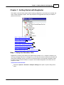
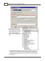
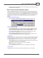
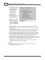
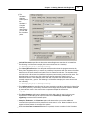
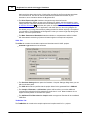


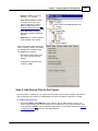
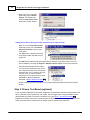
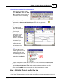
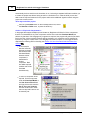
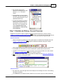
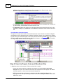

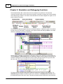
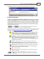


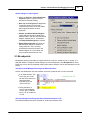
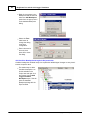
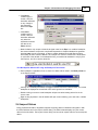


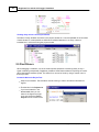
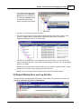

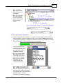
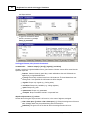
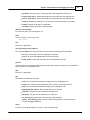
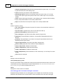
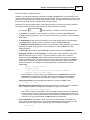
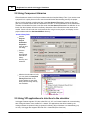


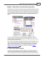
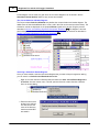
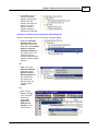
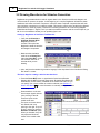
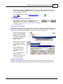

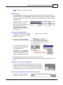
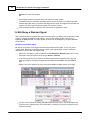

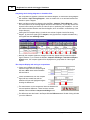
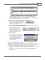
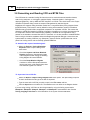

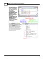
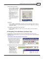
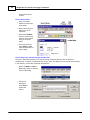
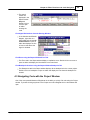

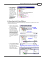
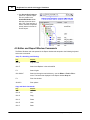

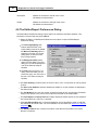


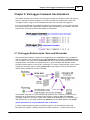

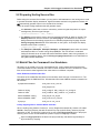
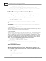


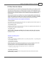
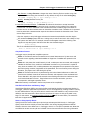

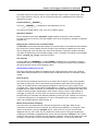

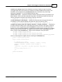
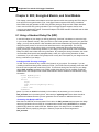
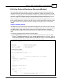

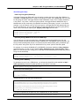
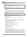

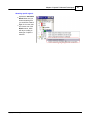
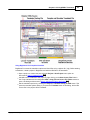

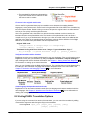
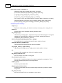

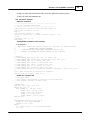
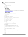
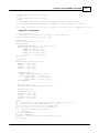
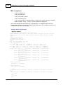
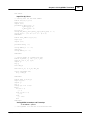
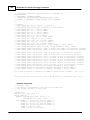
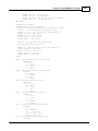


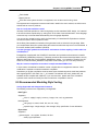
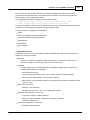

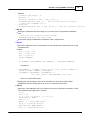


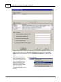


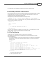
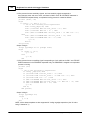

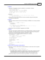


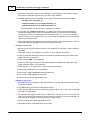
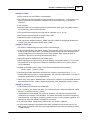

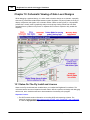

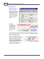
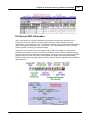
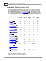


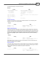
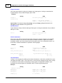
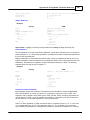
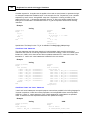
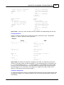


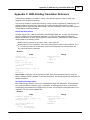


![[ 電子内視鏡 EG-530N2 ] ≫PDF](http://vs1.manualzilla.com/store/data/006530815_2-7d4e6883f302830ee6554d37617cc9ec-150x150.png)