1
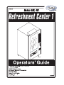
Refreshment Center Operator’s Guide
Table of Contents
TABLE OF CONTENTS
Introduction ................................................................................................................. 1
Power Requirements ............................................................................................................................. 3
Unpack the Machine ............................................................................................................................. 3
Controls and Indicators ......................................................................................................................... 4
Turn the Merchandiser ON and OFF .................................................................................................... 6
Initial Set-Up................................................................................................................ 7
Moving the Merchandiser Through a Narrow Doorway ...................................................................... 7
Open the Rear Outlet Diffuser .............................................................................................................. 9
Position the Merchandiser .................................................................................................................... 9
Configure Machine for Dual Zone...................................................................................................... 10
Tray Set-Up................................................................................................................ 17
Place a Tray in the Loading Position .................................................................................................. 17
Set up Trays to Vend Products ........................................................................................................... 18
Set Up A Tray To Vend Wide Products ............................................................................................. 18
Remove a Snack or Candy Tray ......................................................................................................... 19
Remove a Bottle Tray ......................................................................................................................... 21
Remove and Install Column Dividers................................................................................................. 22
Operate a Tray Outside of the Machine.............................................................................................. 22
Replace a Motor with a Spiral Bearing............................................................................................... 23
Connect and Disconnect a Motor Harness.......................................................................................... 24
Remove and Install Spirals ................................................................................................................. 25
Remove a Spiral Coupler .................................................................................................................... 26
Remove and Install a Spiral Motor ..................................................................................................... 27
Install a Gear ....................................................................................................................................... 28
Install a Spiral Coupler ....................................................................................................................... 29
Move a Tray Up or Down................................................................................................................... 30
Install a Tray in the Merchandiser ...................................................................................................... 31
Install and Remove a Product Spacer ................................................................................................. 32
Load the Merchandiser............................................................................................. 33
General Tray Loading:........................................................................................................................ 33
Special Considerations:....................................................................................................................... 33
Spiral Wall Retainer Usage................................................................................................................. 34
Product Pusher Usage ......................................................................................................................... 35
Configure the Merchandiser to vend “Lunch Buckets”...................................................................... 35
Configure the Merchandiser for Vending "Top Shelf"....................................................................... 36
Return the Trays to the Vending Position........................................................................................... 37
Install and Set Price Labels................................................................................................................. 38
SureVend™................................................................................................................ 41
Health Control ........................................................................................................... 42
Final Installation ....................................................................................................... 44
Level the Merchandiser ...................................................................................................................... 44
Install the Base Plate........................................................................................................................... 45
Install the Lock Cylinder .................................................................................................................... 46
December 2004
i
4800006
Table of Contents
Refreshment Center Operator’s
Install the Optional Cash Box Lock.................................................................................................... 46
Set Up the Coin Mechanism ............................................................................................................... 47
Load the Coin Mechanism .................................................................................................................. 47
Operational Readiness Check ............................................................................................................. 48
Spiral Indexing Procedure (One Spiral, One Motor) .......................................................................... 48
Spiral Indexing Procedure (Two Spirals, One Or Two Motors)......................................................... 49
Test the Bill Validator......................................................................................................................... 49
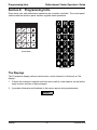
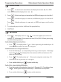
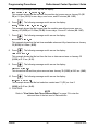
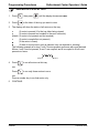
Programming Intro ................................................................................................... 50
The Displays ....................................................................................................................................... 50
The Function Keys.............................................................................................................................. 51
Other Keys .......................................................................................................................................... 51
Control Panel Switches Explained...................................................................................................... 52
Programming Flow Charts.................................................................................................................. 53
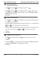
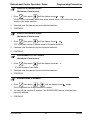
Programming Procedures......................................................................................... 55
Enter a New Supervisor Code ............................................................................................................ 55
Enter a Freevend Code ....................................................................................................................... 55
Lock Or Unlock Mode Or Payout Keys ............................................................................................ 56
Turn Talker Mode On or Off ............................................................................................................. 56
Set DEX Options ............................................................................................................................... 57
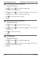
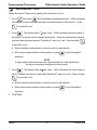
Select Display Language ................................................................................................................... 58
Select Coin Mechanism ..................................................................................................................... 58
Select Card Reader and Options ........................................................................................................ 60
Set Temperature ................................................................................................................................. 64
Enable or Disable Trays ..................................................................................................................... 65
Set SureVendUp the SureVend Anti-Jackpot Feature ...................................................................... 66
Set first in - first out(fifo) mode ......................................................................................................... 68
Show the Temperature in Standby Mode .......................................................................................... 69
View Surevend Software version ....................................................................................................... 70
View Software Version ...................................................................................................................... 70
Set the Date ........................................................................................................................................ 71
Set Daylight Savings Option .............................................................................................................. 71
Set Time-Of-Day Free Vending ......................................................................................................... 72
Set Time-Of-Day Discount Vending ................................................................................................. 72
Time Interval Editing ......................................................................................................................... 72
Select a Standby Message .................................................................................................................. 74
Select a Freevend Message ................................................................................................................ 75
Set Prices ............................................................................................................................................ 78
View Sales Data Three Different Ways ............................................................................................. 79
View Card Reader Paid Sales ............................................................................................................ 79
View Total Paid Vends ...................................................................................................................... 80
Clear All Resettable Data .................................................................................................................. 80
View Amount In Coin Box ................................................................................................................ 81
View Amount In Validator ................................................................................................................ 81
View Discount Sales By Time Interval ............................................................................................. 82
View Free Vends ............................................................................................................................... 82
View Time Data................................................................................................................................. 83
View Total Unpaid Vends ................................................................................................................. 85
4800006
ii
December 2004
Refreshment Center Operator’s Guide
Table of Contents
View Number Of Test Vends ............................................................................................................ 85
View Machine ID Number ................................................................................................................ 85
Test the Motors .................................................................................................................................. 87
Download Data To A PDCD ............................................................................................................. 90
Set Freevend Options ......................................................................................................................... 90
December 2004
iii
4800006
Table of Contents
4800006
Refreshment Center Operator’s
iv
December 2004
Refreshment Center Operators’ Guide
Introduction
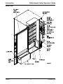
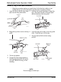
Section 1: Introduction
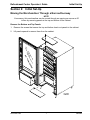
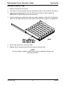
Exterior View
December 2004
1
4800006
Introduction
Refreshment Center Operators’ Guide
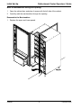
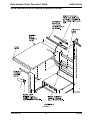
Interior View
4800006
2
December 2004
Refreshment Center Operators’ Guide
Introduction
Power Requirements
The merchandiser is supplied with a service cord for the country of use and is terminated in
a grounding type plug. The wall receptacle used for this merchandiser must be properly
polarized, grounded, and of the correct voltage. Operating the merchandiser from a source
of low voltage will VOID YOUR WARRANTY. Each merchandiser should have its own
electrical circuit and that circuit should be protected with a circuit breaker or fuse conforming
to local regulations.
1. Voltage Check - Place the leads of a voltmeter across the LINE (LIVE) and NEUTRAL
terminals of the wall receptacle. The voltmeter should indicate 110-130 volts AC for 120
volt, 60 Hz locations, or 220- 240 volts AC for 230 volt, 50 Hz locations.
2. Polarity Check - Place the leads of a voltmeter across the LINE (LIVE) and GROUND
terminals of the wall receptacle. The voltmeter should indicate 110-130 volts AC for 120
volt, 60 Hz locations, or 220- 240 volts AC for 230 volt, 50 Hz locations.
3. Noise Potential Check - Place the test leads of a voltmeter across the NEUTRAL and
GROUND terminals of the wall receptacle. The meter should indicate 0 volts AC. A
measurement greater than 1.5 - 2.0 volts AC could result in problems for the
merchandiser's electronic circuitry caused by electrical noise.
Any deviation from these requirements could result in unreliable performance from your
merchandiser.
Unpack the Machine
Remove all packing materials from the interior of the machine. Keep all documents;
warranty cards, etc. Set aside the base plate kit (if present).
December 2004
3
4800006
Introduction
Refreshment Center Operators’ Guide
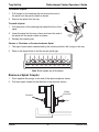
Controls and Indicators
DOOR SWITCH. When the cabinet door is open, this switch turns off the compressor and
evaporator fan.
INTERLOCK SWITCH. (230 volt models only) Turns off the glass heater and display lights
when the cabinet door is open. Pull the switch out to restore high voltage for maintenance.
LOW VOLTAGE SWITCH. Tells the controller software the main door is open or closed.
MESSAGE DISPLAY. This is how the merchandiser communicates with the outside world.
Customers can see messages about how much money they have put into the merchandiser.
The message display also tells customers when a selection is sold out and when vending is
free, inhibited, or discounted. The message display shows you what you are doing when
you program the merchandiser, and can show you what is wrong if there is a failure.
FREE VEND KEYSWITCH (OPTIONAL). This allows someone (other than maintenance
personnel) to set the merchandiser to free vend without opening the door.
SELECTION KEYPAD. The customer uses this keypad to make selections. Maintenance
people may use this keypad during programming.
COIN RETURN BUTTON. Returns any coins paid into the merchandiser prior to a vend.
BILL ACCEPTOR (OPTIONAL). Accepts bills of various denominations, depending upon
the type of bill validator, and how the machine is configured.
SERVICE KEYPAD. The service keypad is located at the top of the monetary panel. It
gives service personnel the means to program, retrieve data from, and view diagnostic
information about, the merchandiser.
4800006
4
December 2004
Refreshment Center Operators’ Guide
Introduction
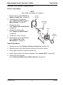
MAIN CONTROLLER PCB DISPLAY. This display consists of two light emitting diodes
(LED) mounted on the controller PCB.
POWER ON
(LED 1)
When lit, this red LED indicates electrical power is applied to the
controller PCB.
HEARTBEAT
(LED 2)
When flashing, this red LED indicates that the controller PCB is
active, and the software is operating.
"CAUTION - Risk of explosion if battery is replaced with an incorrect type. Dispose of used batteries according
to the manufacturer's instructions."
NORMAL CONDITIONS:
When the merchandiser is operating normally, you should see a steady red
POWER ON indicator and a flashing red HEARTBEAT indicator. Contact a
service representative if any other condition exists.
TOP
DC POWER
SUPPLY PCB
FOR 110V COIN MECH
AGC 1
FUSE
1 AMP
˜
Back Side of U.S./Canada Power Panel. The
circuit board mounted on the rear of the power
panel is a DC power supply for the coin
mechanism. A fuse protects the board circuitry in
the event of a coin mechanism solenoid failure. If
the coin mechanism is not working, check this
fuse. If the fuse is blown, a bad coin mechanism
solenoid could be at fault.
BACK SIDE
OF
U.S. / CANADA POWER CONTROL PANEL
December 2004
5
4800006
Introduction
Refreshment Center Operators’ Guide
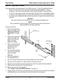
Turn the Merchandiser ON and OFF
I
ON
LABEL
MAIN
POWER
SWITCH
LABEL
O
MAIN
POWER
SWITCH
ELECTRONICS
BREAKER
OFF
LOW VOLTAGE
CIRCUIT BREAKER
626p0040
626P0005
US / CANADA POWER PANEL
•
•
INTERNATIONAL POWER PANEL
Power to the merchandiser is controlled by the main power switch, located on the
power panel.
The power panel is on the right side of the merchandiser, behind the monetary
panel.
WARNING
Lethal voltages are present. Unplug the merchandiser before you perform any of the
following tasks:
•
•
•
•
Change a fuse
Change the fluorescent lamp
Change the lamp starter
Connect or disconnect a harness (except a motor harness when the tray has been
removed)
Failure to do so may result in personal injury.
4800006
6
December 2004
Refreshment Center Operators’ Guide
Initial Set-Up
Section 2: Initial Set-Up
Moving the Merchandiser Through a Narrow Doorway
NOTE
If necessary, this merchandiser can be moved through an opening as narrow as 30
inches by removing panels at the top and bottom of the cabinet.
Remove the Bottom and Top Panels:
1. Remove the screws that secure the top and bottom knock-out panels to the cabinet.
2. Lift panels upward to remove them from the cabinet.
December 2004
7
4800006
Initial Set-Up
Refreshment Center Operators’ Guide
Move the Merchandiser through the Opening:
1. Open the cabinet door and place it square with the left side of the cabinet.
2. Carefully walk the merchandiser through the opening.
Reassemble the Merchandiser:
1. Replace the upper and lower panels.
4800006
8
December 2004
Refreshment Center Operators’ Guide
Initial Set-Up
Open the Rear Outlet Diffuser
The rear outlet diffuser vents warm air up and out of the back of the merchandiser, away
from the air inlet (on the bottom of the cabinet). It is shipped in the closed position and must
be opened before the merchandiser is put into service.
1. Remove the two screws holding
the upper corners of the diffuser
against the back of the cabinet.
Notice the two unused screw holes
at the corners.
NOTE:
Wear protective gloves when
bending diffuser to prevent
injury.
2. Pull the top of the diffuser away
from the cabinet, then bend the
diffuser so that the unused screw
holes align with the holes in the
cabinet.
3. Use the two screws removed in
step one to affix the diffuser to the
cabinet in its new “open” position.
CAUTION
The merchandiser will not function properly if the Rear Outlet Diffuser is not open!
Position the Merchandiser
Move the merchandiser to its approximate position. There are certain procedures you
need to perform before it is in its permanent location. Plug in your merchandiser and turn
the power switch to ON.
•
•
•
•
You can position this merchandiser anywhere in a bank of machines. It can even
be placed on an end flush against a side wall.
The merchandiser should be placed at least four inches away from the back wall
(six inches if rear diffuser is not installed). This will provide adequate air circulation
for the refrigeration unit. This will provide adequate air circulation for the
refrigeration unit.
The merchandiser will operate more efficiently when placed in a shaded location.
There should be enough room in front of the merchandiser for the door to move
freely.
CAUTION
This machine is only rated for installation at an indoor location.
December 2004
9
4800006
Initial Set-Up
Refreshment Center Operators’ Guide
Configure Machine for Dual Zone
To configure your machine for dual zone you must first know what duct system your machine
has. There are two different duct systems. There is a version 1 duct system which uses a tall
air supply panel (as shown in figure 1 and 2). This air supply panel will extend all the way to
the top of the machine. Version 2 duct system which uses a short air supply panel (as shown
in figure 3) will only extend about half way up the machine.
Both duct systems have two different configurations for the dual zone option. There is a two
tray configuration and a three tray configuration.
If you have a version 1 duct system and you are configuring your machine for a two tray
configuration: (See Figure , “Figure 1,” on page 11)
If you have a version 1 duct system and you are configuring your machine for a three tray
configuration: (See Figure , “Figure 2,” on page 13)
If you have a version 2 duct system and you are configuring your machine for a two tray or a
three tray configuration: (See Figure , “Figure 3,” on page 15)
Note:
If you are not using dual zone in the merchandiser then you must remove the
barrier, foam boards, air deflector, and the air plate.
The temperature sensor will be mounted on the top left hand
side of the cabinet.
4800006
10
December 2004
Refreshment Center Operators’ Guide
Initial Set-Up
Set machine for two tray configuration version 1:
FIGURE 1
December 2004
11
4800006
Initial Set-Up
Refreshment Center Operators’ Guide
Version 1 duct system two tray configuration
(See Figure , “Figure 1,” on page 11)
1. You must first remove all trays from your merchandiser.
2. Remove the right tray rail guide for tray A shelf.
3. Remove the tray rail board and the tray shield from the second tray guide rail in the
machine.
4. Re-attached the tray shield to the second tray rail.
5. Mount the tray rail board and the to the right side of the barriers mounting rail standoffs.
6. Remove the temperature sensor bracket mounted to the left hand side of the cabinet.
Do not unplug the sensor, let it hang down the left hand side of the cabinets wall.
7. Position the barrier inside the cabinet just below the second trays rails. Make sure that
the third tray rail connector plug is left underneath the barrier. You will need to remove
the left hand side tray rails underneath the barrier in order to position the barrier.
8. Mount the barriers mounting rails to the sides of the machine using one screw for each
rail.
9. Move the barrier to the back right corner of the cabinet leaving a gap on the left hand
side of the barrier.
10. Place the 1/2” by 1/2” piece of foam tape on the left side of the cabinet in between the
barrier and the cabinet where you have left the gap.
11. Place the large foam board at the upper right side of the air supply panel.
12. Place the small foam board next to the large foam. Make sure that the small boad is at
the bottom of the large board.
13. Bend the flanges on the air supply panel to hold the foam boards in place.
14. Mount the air plate directly under the barrier on the right side of the air supply panel.
15. Mount the air deflector in front of the air plate under the barrier. (The opening should be
facing you.)
16. Re-mount all tray rails and re-connect all rail connections.
17. Replace all snack and candy trays. You may have to adjust the tray rails underneath the
barrier to provide adequate spacing for your trays.
18. Re-mout the temperature probe underneath the barrier in the holes provided on the left
inside wall of the cabinet.
4800006
12
December 2004
Refreshment Center Operators’ Guide
Initial Set-Up
Set the machine for three tray configuration version 1:
Note:
If you are using a three tray configuration you will not use the air deflector and
the air plate.
FIGURE 2
December 2004
13
4800006
Initial Set-Up
Refreshment Center Operators’ Guide
Version 1 Duct system three tray configuration
(See Figure , “Figure 2,” on page 13)
1. You must first remove all trays from your merchandiser.
2. Remove the right two tray rail guides for tray A and B shelf.
3. Remove the tray rail board and the tray shield from the third tray guide rail in the
machine.
4. Re-attached the tray shield to the third tray rail.
5. Mount the tray rail board and to the right side of the barriers mounting rail standoffs.
6. Remove the temperature sensor bracket mounted to the left hand side of the cabinet.
Do not unplug the sensor, let it hang down the left hand side of the cabinets wall.
7. Position the barrier inside the cabinet just below the third trays rails. Make sure that the
fourth tray rail connector plug is left underneath the barrier. You will need to remove the
left hand side tray rails underneath the barrier in order to position the barrier.
8. Mount the barriers mounting rails to the sides of the machine using one screw for each
rail.
9. Move the barrier to the back right corner of the cabinet leaving a gap on the left hand
side of the barrier.
10. Place the 1/2” by 1/2” piece of foam tape on the left side of the cabinet in between the
barrier and the cabinet where you have left the gap.
11. Place the large foam board at the upper right side of the air supply panel.
12. Place the small foam board directly underneath the large foam.
13. Bend the flanges on the air supply panel to hold the foam boards in place.
14. Re-mount all tray rails and re-connect all rail connections.
15. Replace all snack and candy trays. You may have to adjust the tray rails underneath the
barrier to provide adequate spacing for your trays.
16. Re-mout the temperature probe underneath the barrier in the holes provided on the left
inside wall of the cabinet.
4800006
14
December 2004
Refreshment Center Operators’ Guide
Initial Set-Up
Set the machine for a two or three tray configuration version 2:
FIGURE 3
December 2004
15
4800006
Initial Set-Up
Refreshment Center Operators’ Guide
Version 2 Duct System
(See Figure , “Figure 3,” on page 15)
1. You must first remove all trays from your merchandiser.
2. Remove the right tray rail guide for tray A shelf.
3. For steps 4-8 substitute third tray for second tray if configuring machine for three tray
configuration.
4. Remove the tray rail board and the tray shield from the second tray guide rail in the
machine.
5. Re-attached the tray shield to the second tray rail.
6. Mount the tray rail board to the right side of the barriers mounting rail standoffs.
7. Remove the temperature sensor bracket mounted to the left hand side of the cabinet.
Do not unplug the sensor, let it hang down the left hand side of the cabinets wall.
8. Position the barrier inside the cabinet just below the second trays rails. Make sure that
the third tray rail connector plug is left underneath the barrier. You will need to remove
the left hand side tray rails underneath the barrier in order to position the barrier.
9. Mount the barriers mounting rails to the sides of the machine using one screw for each
rail.
10. Move the barrier to the back right corner of the cabinet leaving a gap on the left hand
side of the barrier.
11. Place the 1/2” by 1/2” piece of foam rope on the left side of the cabinet in between the
barrier and the cabinet where you have left the gap.
12. Re-mount all tray rails and re-connect all rail connections.
13. Replace all snack and candy trays. You may have to adjust the tray rails underneath the
barrier to provide adequate spacing for your trays.
14. Re-mout the temperature probe underneath the barrier in the holes provided on the left
inside wall of the cabinet.
4800006
16
December 2004
Refreshment Center Operators’ Guide
Tray Set-Up
Section 3: Tray Set-Up
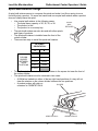
Place a Tray in the Loading Position
1. Place both hands on the tray as shown.
2. Push down on the tray latches with your thumbs.
3a. Bottle Trays: Pull the tray toward you until the slides are fully extended. The bottle tray
can now be loaded--bottle trays do not tilt like snack and candy trays.
3b. Snack and Candy Trays: Pull the tray toward you until you hear and feel the rear tray
rollers drop into a cut-out in the top of the guide rail.
TRAY
LATCH
PULL
TRAY
LATCH
157P0011
4. Continue pulling the tray forward for another inch. You will then be able to tilt the tray
downward into the loading position as shown.The candy or snack tray is now ready for
loading.
SNACK OR CANDY TRAY IN THE LOADING POSITION
NOTE
When the cabinet door is not fully open, the bottom tray will rest on the delivery pan
assembly. Handle the tray with care to avoid scratching the delivery pan assembly.
December 2004
17
4800006
Tray Set-Up
Refreshment Center Operators’ Guide
Set up Trays to Vend Products
These instructions will guide you through setting up your trays for vending. You will be asked
to determine if your tray can physically hold the products you intend to vend. If not, you will
be directed to other procedures which will help you get them set up. Follow these nine steps
for each tray in your machine:
1. Make sure the tray is in the loading position.
2. Is the column wide enough for the intended product? If so, proceed to the next step.
Otherwise, set up your tray to vend wider products (see below, this page). When you're
done, return to step 3 in this procedure.
3. Will the products fit between the spiral turns? If so, proceed to the next step.
Otherwise, change the spiral.
4. Will the product pass under the tray immediately above? If so, proceed to the next step.
Otherwise, reposition the tray and guides.
5. Will the product touch products on either side? If not, proceed to the next step.
Otherwise, install a product spacer.
6. Load products in the tray.
7. Return the tray to the vending position.
8. Install the price rolls.
9. Install the selection ID numbers.
Set Up A Tray To Vend Wide Products
The following steps will help you configure your tray to vend wide products. When you are
done with the entire wide product steps, return to the set-up procedures above.
NOTE:
Does not apply to bottle trays - they cannot be reconfigure.
1. Remove the tray from the merchandiser and place it on a flat surface.
2. Based on the size of the product you want to vend, decide how many spiral positions it
will occupy. Please remember that the left most spiral in the group must have an even
ID number (0, 2, 4, etc.) For example, if a product is three spirals wide, the left spiral will
be ID number 0, and the right spiral will be ID number 2. Be careful how wide you set up
for, because some wide products could get hung up in the delivery door.
3. Remove the column dividers inside the group. In the example of three spiral positions,
you would be removing the dividers between spiral ID numbers 0 and 1, and 1 and 2.
4. If your group only consists of 2 spirals, replace the right most motor with a spiral bearing
and gear, and install a gear on the left most motor. Skip to step 8.
5. Remove all spirals in the group except the left most spiral.
4800006
18
December 2004
Refreshment Center Operators’ Guide
Tray Set-Up
6. Do one of the following:
a. If your group has an ODD number of spirals (3, 5, etc.) remove the harnesses from
all motors in the group except the left most one. To the right most motor, connect the
harness from the motor immediately to its left.
b. If your group has an EVEN number of spirals (4, 6, etc.) remove the harnesses from
all motors inside the group (leave the harnesses connected to the left most and right
most motors).
7. Install a spiral at the right most position in your group. Make sure it has the same
product capacity and is opposite to the one in the left most position.
8. Return the tray to the merchandiser.
9. Electronically couple the motors as needed (see "Couple/Uncouple Tray Motors" on
page 67).
10. Return to step 3 in the "Set up Trays to Vend Products" on page 18.
Study this procedure before you install a tray for the first time; while you are holding the tray
you will not be able to see this area.
Remove a Snack or Candy Tray
1. Remove all product from the tray.
2. Push down on the tray latches
with your thumbs.
3. Pull the tray toward you until you
hear and feel the rear tray rollers
drop into a cut-out in the top of
the guide rail.
TRAY
LATCH
PULL
TRAY
LATCH
TRAY
LATCH
TRAY
GUIDE
RAIL
December 2004
19
4800006
Tray Set-Up
Refreshment Center Operators’ Guide
4. Unplug the tray wiring harness from the
PC board mounted on the tray guide rail
IMMEDIATELY ABOVE the tray you are
removing.
PC BOARD
ATTACHED TO
TRAY GUIDE
TRAY GUIDE RAIL
REAR OF TRAY
5. Lift up on the tray and slide it toward the
back. No more than an inch should be needed
6. The tab near the back of the tray should
align with the cut-out in the top of the guide rail
as shown.
TRAY
ROLLER
TRAY
GUIDE
RAIL
157P0026
7. Lift the tray clear of the guide rail and out of the
merchandiser.
CAUTION
When the cabinet door is not fully open, use extra
care in removing the bottom tray. Failure to do
so may result in damage to the tray or to
the delivery pan assembly.
4800006
20
CUT-OUT
TAB
(ON TRAY)
REAR OF
TRAY
TRAY GUIDE
RAIL
December 2004
Refreshment Center Operators’ Guide
Tray Set-Up
Remove a Bottle Tray
1. Remove all product from the tray.
2. Push down on the tray latches with your thumbs and slide out the tray as far as it will go.
3. Unplug the tray wiring harness from the PC board mounted on the tray guide rail
IMMEDIATELY ABOVE the tray you are removing.
4. Locate a small lever on each side of the tray, where it attaches to the slide. The left lever
will be up, the right will be down. Press down on the left lever and up on the right lever.
5. Pull the tray towards you, off of the slides.
6. Replace the tray by performing the above steps in reverse order.
NOTE:
It is much easier to replace a bottle tray if you have assistance lining up the
tray rails and slides.
December 2004
21
4800006
Tray Set-Up
Refreshment Center Operators’ Guide
Remove and Install Column
Dividers
2
Note: Not applicable to bottle trays.
1. Push the column divider toward the
back of the tray - 1 .
2. Lift the column divider clear of the tray 2 .
1
3. Install the column divider in the reverse
order of removal.
COLUMN
DIVIDER
Operate a Tray Outside of the Machine
Use tray harness extension (P/N
1709018) available from your National
Vendors Parts department (1-800621-7278). The extension will enable
you to remove the tray from the
machine and still operate the motors
and spirals. Connect it as shown
below:
4800006
22
December 2004
Refreshment Center Operators’ Guide
Tray Set-Up
Replace a Motor with a Spiral Bearing
Remove A Motor:
1. Disconnect the harness from the motor.
(See "Connect and Disconnect a Motor Harness" on page 24).
2. Remove the spiral. (See "Remove and Install Spirals" on page 25).
3. Remove the spiral coupler. (See "Remove a Spiral Coupler" on page 26).
4. Remove the motor. (See "Remove and Install a Spiral Motor" on page 27).
5. Install A Spiral Bearing:
a. Put the gear into position in this set-up as shown.
SPIRAL
BEARING
BACKWALL
OF TRAY
GEAR
˜
SPIRAL
COUPLER
b. Install the spiral coupler. (See "Install a Gear" on page 28).
December 2004
23
4800006
Tray Set-Up
Refreshment Center Operators’ Guide
Connect and Disconnect a Motor Harness
CAUTION
To avoid breaking the motor circuit board, hold the header on the circuit board
whenever connecting or disconnecting a motor harness.
Disconnect a Motor Harness:
1. Pull the harness connector away from the circuit board as shown.
2. Tuck the unused part of the harness out of the way in the trough at the back of the tray.
Connect a Motor Harness:
1. Locate the harness connector for the appropriate tray position.
2. Push the harness connector over the header pins on the motor circuit board as shown.
4800006
24
December 2004
Refreshment Center Operators’ Guide
Tray Set-Up
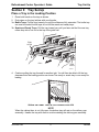
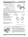
Remove and Install Spirals
•
•
All spirals are the same diameter
There are two kinds of spirals
Counter Clockwise (left-hand)
Clockwise (right-hand)
SNACK AND CANDY TRAY SPIRAL OPTIONS
COUNTER CLOCKWISE
(LEFT HAND)
CLOCKWISE
(RIGHT HAND)
SPIRAL
COUNT
RETAINER
COLOR
ASSEMBLY
SPIRAL
ASSEMBLY
SPIRAL
RETAINER
6
PURPLE
1477103
1477102
1477105
1477104
1477107
8
BLACK
1677247
1677190
1677248
1677189
1477073
9
GRAY
1477152
1477153
1477149
1477150
1477155
11
BLUE
1477023
1477024
1477026
1477027
1457061
13
YELLOW
1477029
1477030
1477032
1477033
1457062
15
RED
1477035
1477036
1477038
1477039
1457063
17
BROWN
1477101
1477100
1477099
1477098
1477106
20
WHITE
1477041
1477042
1477044
1477045
1457064
25
GREEN
1477047
1477048
1477050
1477051
1457065
30
BLACK
1477053
1477054
1477056
1477057
1477073
38
ORANGE
1477059
1477060
1477062
1477063
1467137
NOTE
Bottle trays use a 3.25” diameter spiral.
BOTTLE TRAY SPIRAL OPTION
December 2004
SPIRAL
COUNT
RETAINER
COLOR
ASSEMBLY
SPIRAL
RETAINER
6
DARK GREEN
7807011
7807003
4407822
7
RED
7807015
7807016
1457063
25
4800006
Tray Set-Up
Refreshment Center Operators’ Guide
To Remove a Spiral:
1. Pull forward on the retaining clip and remove the end of
the spiral from the spiral coupler as shown.
LIFT
2. Remove the spiral from the tray.
SPIRAL
COUPLER
To Install a Spiral:
PULL
1. Pull the bottom of the retaining clip toward the front of the
spiral.
2. Lower the spiral into the tray column and insert the end of
the spiral into the spiral coupler as shown.
SPIRAL
RETAINING
CLIP
3. Release the retaining clip.
Choose a Clockwise or Counterclockwise Spiral
1. The type of spiral used is determined by the column position it will occupy in the tray.
2. Refer to the figure below to find the correct spiral type.
A0
A1
A2
A3
A5
A4
A6
A7
A8
A9
Note: Bottle spirals are all clockwise.
Remove a Spiral Coupler
1. Pinch together the prongs on the end of the spiral coupler as shown.
2. Pull the coupler forward (in the direction of the arrow as shown)
SPIRAL
COUPLER
PRONGS
PULL
4800006
26
December 2004
Refreshment Center Operators’ Guide
Tray Set-Up
Remove and Install a Spiral Motor
Remove a Spiral Motor:
NOTE
Some steps may already be completed
1. Remove the tray. (See "Remove a
Snack or Candy Tray" on page 19).
SPIRAL
MOTOR
2. Disconnect the motor harness.
(See "Connect and Disconnect a
Motor Harness" on page 24).
BACKWALL
OF TRAY
3. Remove the spiral.
(See "Remove and Install Spirals"
on page 25).
GEAR
˜
4. Remove the spiral coupler.
(See "Remove a Spiral Coupler"
on page 26).
SPIRAL
COUPLER
5. Lift the motor clear of the tray.
6. Return the tray to the merchandiser.
(See "Install a Tray in the
Merchandiser" on page 31).
Install a Spiral Motor:
1. Remove the tray. (See "Remove a Snack or Candy Tray" on page 19).
2. Place the motor in the correct position at the rear of the tray as shown.
3. Place a gear in position if required by this set-up.
4. Install a spiral coupler in the proper orientation. (See "Install a Gear" on page 28).
5. Connect the motor harness.
(See "Connect and Disconnect a Motor Harness" on page 24).
December 2004
27
4800006
Tray Set-Up
Refreshment Center Operators’ Guide
Install a Gear
Use a Gear when:
• Gears are used to mechanically couple the spirals together.
• This happens whenever you have two spirals and only one motor for vending a
selection.
Position the Gear
•
•
Place the gear in between the back of the tray and the spiral coupler.
There are two possible orientations for the gear:
BACK WALL
OF TRAY
GEAR
ORIENTATION 1
•
ORIENTATION 2
There are two rules to follow when orienting gears:
RULE 1 The gears for selections next to each other cannot use the same
orientation.
RULE 2 All gears for a single selection must use the same orientation.
4800006
28
December 2004
Refreshment Center Operators’ Guide
Tray Set-Up
Install a Spiral Coupler
1. Place the gear in position if one is required for this set-up.
When Used with a Motor:
2. Hold the motor in place
and push the spiral
coupler through the motor
gear box until it clicks into
position. Be sure the
spiral couplers are
oriented as shown below.
NOTE
The motor output shaft
opening contains eight facets
to allow the spiral coupler to
be installed in any one of
eight positions.
SPIRAL
COUPLER
FRONT VIEW OF
MOTOR OUTPUT SHAFT
MOTOR
Spiral Coupler Orientation
ONE POSITION
COUNTERCLOCKWISE
FROM VERTICAL
ONE POSITION
CLOCKWISE
FROM VERTICAL
LEFT SPIRAL
COUPLER
RIGHT SPIRAL
COUPLER
AS VIEWED FROM FRONT OF TRAY
When Used with a Coupler Bearing:
3. Hold the coupler bearing in place and push
the spiral coupler through the bearing until
the coupler clicks into position. Be sure the
coupler is in the proper orientation as
shown.
SPIRAL
COUPLER
SPIRAL
BEARING
December 2004
29
4800006
Tray Set-Up
Refreshment Center Operators’ Guide
Move a Tray Up or Down
This merchandiser can be adjusted to vend taller products. Follow the guidelines below:
• Keep in mind that when you increase the product height available to a tray by
lowering it, you will be decreasing the product height available to the tray below.
• If a tray is in the lowest position, the tray below it should not be in the highest position.
• If a tray is in the highest position, the tray above should not be in the lowest position.
• You may need to experiment with various tray positions to get the best results for your
products.
CAUTION
The trays in should not be positioned over an open air discharge vent.
NOTE
Tray movement is limited because the tray harness will limit the amount of
travel available to the tray guide rails.
Proceed as follows:
1. Remove the tray from
the merchandiser. (See
REAR GUIDE
MOUNTING CHANNEL
"Remove a Snack or
Candy Tray" on page
19).
2. Remove the screw that
secures the right tray
guide rail to the front
PC BOARD
FRONT GUIDE
guide mounting
MOUNTING CHANNEL
channel as shown.
CHANNEL
3. Tap up on the guide rail
SLOT
and unseat the guide
rail tabs from the
channel slots.
4. Pull the guide rail away
TRAY
GUIDE
from the front and rear
RAIL
guide mounting
channels.
SCREW
5. Move the guide rail to
the desired position.
6. Insert the guide rail tabs into the mounting channel slots as shown.
7. Tap down on the guide rail to seat the tabs in the channel slots.
8. Replace the screw that secures the guide rail to the front guide mounting channel.
9. Repeat steps 2 through 8 for the left guide rail.
10. Return the tray to the merchandiser.
(See "Install a Tray in the Merchandiser" on page 31).
11. Load products into the trays, and perform test vends. Make sure the trays don't interfere
with the products you are vending, and that all products vend properly.
4800006
30
December 2004
Refreshment Center Operators’ Guide
Tray Set-Up
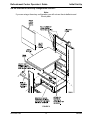
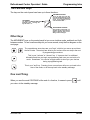
Install a Tray in the Merchandiser
•
Study this procedure before you install a tray for the first time; while you are
holding the tray you will not be able to see this area. Proceed as follows:
1. Insert the tray so that the tray rollers 5. Hold the tray up while pushing it toward the
pass over the tray guide rollers.
rear. Stop when the tab on the tray aligns
with the opening in the tray guide.
REAR OF
TRAY
CUT-OUT
TRAY
GUIDE
TRAY
ROLLER
157P0024
FRONT OF
RAIL
157P0012
TAB
2. Bring the tray roller to rest on the tray 6. Lower the tray until it rests on the tray guide
guide.
roller. Push the tray in all the way.
REAR OF TRAY
7. The tray latch will fall into the locking
position.
CUT-OUT
TRAY
ROLLER
TRAY
GUIDE
RAIL
REAR OF
TRAY
157P0026
3. Tilt the tray upward.
4. Connect the tray wiring harness to
the PC board mounted to the guide
rail JUST ABOVE the tray you are
installing.
TAB
(ON TRAY)
157P0025
TRAY GUIDE
RAIL
NOTE:
Does not apply to bottle trays.
December 2004
31
4800006
Tray Set-Up
Refreshment Center Operators’ Guide
Install and Remove a Product Spacer
Install a Product Spacer
The product spacer will keep
a tall, narrow product upright.
PRODUCT
SPACER
MOUNTING
PINS
Shown at right are spacers
and column dividers on both
deep and shallow trays.
Insert the product spacer onto
the column divider as shown.
MOUNTING
PINS
COLUMN
DIVIDER
Adjust a Product Spacer
With product loaded in the
tray, rotate the product spacer
up or down to keep the
product upright as shown.
Remove a Product Spacer
Pull the product spacer
mounting pins from the
column divider.
4800006
32
December 2004
Refreshment Center Operators’ Guide
Load the Merchandiser
Section 4: Load the Merchandiser
The color of the spiral coupler (the little plastic tab attached to the rear of the spiral will tell
you how many products will fit in the spiral. (See table below).
NOTE
Another way to determine spiral capacity is to count the spaces in the spiral!
SPIRAL CAPACITY COLOR CODES
SPIRAL
SPIRAL COUPLER
SPIRAL SPIRAL COUPLER
CAPACITY
COLOR
CAPACITY
COLOR
6
8
9
11
13
15
Purple
Black
Gray
Blue
Yellow
Red
17
20
25
30
38
Brown
White
Green
Black
Orange
General Tray Loading:
•
•
•
•
•
See "Product Pusher Usage" on page 35 for spirals with capacity of 11, 13, or 15.
See "Spiral Wall Retainer Usage" on page 34 for spirals with capacity of 20, 25, 30,
or 38.
Begin loading products at the front of the tray and work toward the back. Position the
product so the package rests on the tray. DO NOT force a product into a spiral.
If the fit is too tight or too loose, change the spiral size.
(See "Remove and Install Spirals" on page 25).
Be sure there are no empty positions between products in each spiral.
Special Considerations:
Bagged Products Position package upright, then push the tops slightly toward the rear of
the tray. Also, (see "Product Pusher Usage" on page 35).
Thin Packages
Position the package upright.
Also, (see "Spiral Wall Retainer Usage" on page 34).
KitKat
The two right-most columns of the candy tray are designed to accept the
KitKat candy bar.
December 2004
33
4800006
Load the Merchandiser
Refreshment Center Operators’ Guide
Spiral Wall Retainer Usage
A spiral wall retainer serves to compress the spiral and make it act like a spring to more
forcefully eject a product. Do some test vends and use a spiral wall retainer when a product
does not readily leave the spiral.
•
•
•
•
Use a spiral wall retainer in the following cases:
• The spiral has a capacity of 20, 25, 30, or 38.
• The product is thin.
• The product is on a candy tray.
The spiral wall retainer can also be used with other spirals
and types of products.
The spiral wall retainer is installed near the front of the
column divider.
There are two ways to install the spiral wall retainer.
SPIRAL
WALL
RETAINER
RETAINER
ORIENTATION
COLUMN
DIVIDER
BETWEEN
THESE
POSITIONS
A
B
0 and 1
1 and 2
2 and 3
3 and 4
4 and 5
5 and 6
6 and 7
7 and 8
8 and 9
•
•
To install a spiral wall retainer, insert the retainer in the square slot near the front of
the column divider.
The spiral wall retainer must be removed in two cases:
• A KitKat bar loaded into either of the two right hand positions of a tray will not
clear the retainer on the column divider between the two positions.
• A product pusher will catch on
DIVIDER
a retainer in ORIENTATION A.
ORIENTATION A
4800006
34
ORIENTATION B
December 2004
Refreshment Center Operators’ Guide
Load the Merchandiser
Product Pusher Usage
The product pusher will give the top of a product an
extra tilt to help it fall into the delivery pan.
PRODUCT
PUSHER
Use a product pusher in the following cases:
•
•
The spiral has a capacity of 15, 13, or 11.
The package is non-rigid like bagged
peanuts
The product pusher can also be used with other
spiral and types of products.
A bag of product pushers has been shipped with the
merchandiser. Additional product pushers are
available from the National Vendors' parts department (800-621-7278). To use a product
pusher, snap it on the spiral as shown. You can adjust the product pusher by moving it
around on the spiral to achieve the best vending results.
Configure the
Merchandiser to vend
“Lunch Buckets”
ONE POSITION
COUNTERCLOCKWISE
FROM VERTICAL
ONE POSITION
CLOCKWISE
FROM VERTICAL
Because of the weight and shape of the
package, National Vendors
recommends that this product be
vended only from the bottom tray.
To vend this product, two adjacent
positions must be coupled together.
LEFT SPIRAL
COUPLER
The left spiral coupler should be
installed one position counterclockwise
from the vertical position.
RIGHT SPIRAL
COUPLER
AS VIEWED FROM FRONT OF TRAY
FOOD SELECTIONS
LOADED IN SPIRALS
157P0039
December 2004
The right spiral coupler should be installed one position
clockwise from the vertical position.
Replace the current spirals with six-count spirals.
These are available from the National Vendors parts
department. (See "Remove and Install Spirals" on
page 25). A pad can be installed in the bottom of the
delivery pan to quiet and cushion product delivery. This
part is available from the National Vendors parts
department. Load "Lunch Bucket" products as shown
at left.
35
4800006
Load the Merchandiser
Refreshment Center Operators’ Guide
Configure the Merchandiser for Vending "Top Shelf"
National Vendors recommends that this product be vended from a candy tray.
1. Move the tray so the package can be loaded standing on its left or right edge.
( See "Move a Tray Up or Down" on page 30).
2. The following steps must be completed for three adjacent positions on the tray:
NOTE
The left-most position in the group of three must be an even numbered position.
3.
LEAVE THIS MOTOR
CONNECTOR ALONE
1. REMOVE COLUMN
DIVIDERS
2. REMOVE
SPIRALS
4.
DISCONNECT THIS
MOTOR CONNECTOR
5.
MOVE CONNECTOR
FROM THIS MOTOR
6.
TO THIS MOTOR
7. INSTALL AN 11-COUNT LEFT HAND
SPIRAL IN THIS POSITION
8. INSTALL AN 11-COUNT RIGHT-HAND
SPIRAL IN THIS POSITION
157P0040
NOTE
If the motor harness disconnected in step 5 does not reach, use the motor skip harness, (P/
N 1599024), available from the National Vendors Parts Department (800-621-7278).
TOP SHELF
PRODUCT
3. Couple the left motor to the right motor. (See "Couple/Uncouple Tray Motors" on
page 67).
4. Load the "Top Shelf" products as shown.
4800006
36
December 2004
Refreshment Center Operators’ Guide
Load the Merchandiser
Return the Trays to the Vending Position
1. Lift the tray until it is parallel to the floor as shown.
TRAY
LATCH
PULL
TRAY
LATCH
157P0011
2. Push the tray toward the back of the cabinet. The tray latches on the sides of the tray
will lock into position.
TRAY
LATCH
TRAY
GUIDE
RAIL
157P0027
December 2004
37
4800006
Load the Merchandiser
Refreshment Center Operators’ Guide
Install and Set Price Labels
•
•
•
Price rolls are printed on coiled strips as shown in the illustration below. (The dollar
and cents rolls are factory installed.) If you use another type of currency, you will find
the appropriate price rolls in the plastic bag that contained this manual.
There are two types of price rolls:
Dollar roll 1 to 12, increments of 1
Cents roll 00 to 95, increments of 05
Remove the price rolls as required, and install the appropriate ones for your currency.
DOLLAR ROLL
157P0043
CENTS ROLL
Install Price Labels:
There are three pairs of slots in the front of the can unit for each position. Install per this
example:
1. Insert the dollar roll in the left-most pair of slots as shown if the price is $1.00 or more.
2. Insert the cents roll in the center pair of slots as shown.
3. The low-number end of the roll
goes in the top slot and the highnumber end of the roll goes in the
bottom slot.
PRESS TOP OF ROLL
PAST FLEXIBLE TAB
NEAR TOP EDGE
INSERT BOTTOM OF ROLL
THROUGH SLOT ALONG
157P0044
BOTTOM EDGE
4800006
38
December 2004
Refreshment Center Operators’ Guide
Load the Merchandiser
Adjust the Price Roll:
You can set selection prices within the following range:
Minimum price $.00
Maximum price $99.99
Increment
$.05
1. Use your thumb as shown to move each price roll up or down as needed to set the
desired price.
NOTE
You will see the word STOP near either end of the roll.
157P0045
Selection ID numbers are printed on clear plastic sheets. You will find these in the plastic
bag that contained this manual. You will need to separate them along the scored lines
between the selections. BE CAREFUL when doing this, as it is easy to split the labels.
Install the Selection ID Numbers:
1. Press together the two long edges of the selection ID label.
2. Snap the selection ID label into position on the front of the tray as shown.
DOLLAR
PRICE ROLL
CENTS
PRICE ROLL
SELECTION
IDENTIFICATION
157P0059
December 2004
39
SELECTION
IDENTIFICATION LABEL
4800006
Load the Merchandiser
Refreshment Center Operators’ Guide
See the figures below for snack and candy tray positions.
MOTOR POSITION
TOP TRAY
BOTTOM TRAY
TRAY A
A0
A1
A2
A3
A4
A5
A6
A7
A8
A9
TRAY B
B0
B1
B2
B3
B4
B5
B6
B7
B8
B9
TRAY C
C0
C1
C2
C3
C4
C5
C6
C7
C8
C9
NOTE
This example shows a 3-tray merchandiser.
Some merchandisers can have up to 6 trays.
Example of a Basic
Snack Tray ID Label to Use
A0
A2
A4
A6
A8
Example of a Basic
Candy Tray ID Label to Use
A0
4800006
A1
40
A2
A3
A4
A5
A6
A7
A8
A9
December 2004
Refreshment Center Operators’ Guide
SureVend™
Section 5: SureVend™
The SureVend™ product detection system consists of several infrared light emitters and
infrared light detectors that scan the product delivery area with a pattern of crisscrossed light
beams. While the machine is idle, the SureVend™ system is constantly calibrating itself for
optimum performance in all temperature, humidity, dust, and alignment conditions. The
SureVend™ detection system is used by the controller to assure that the selected product is
delivered.
•
•
•
•
•
•
When a customer makes a selection, the controller checks that the SureVend™
detection system is ready and tells it to begin scanning for the product. Different
scanning patterns are used depending upon the size and shape of the product.
The vending machine controller then starts the delivery motor and constantly
checks the SureVend™ system for detection of the delivered product.
If no product delivery is detected, the controller continues to run the delivery motor
for up to three revolutions, pausing momentarily at the home position of each
revolution of the motor.
If no product is detected after the third revolution, the selection is marked as
empty and the customer's credit is optionally restored to make another selection
or is automatically returned.
If product delivery is detected before the delivery motor has come to the home
position for the first time, the delivery motor continues running to its home
position.
If the delivery motor has already passed the first home position, the motor will stop
immediately upon product detection to avoid the possibility of vending a second
product.
NOTE:
A fatal malfunction in the SureVend™ detection system during the
vend is treated the same as a product delivery. It is assumed
that the malfunction is due to tampering or vandalism.
Anti-Jackpot provides protection against unforeseeable cheating of the SureVend™ system.
If a certain number of SureVend™ empty conditions occur, SureVend™ will disable itself for
a few minutes. A SureVend™ empty condition occurs when product delivery is not detected
and the customer's money is restored or returned. Both the number of SureVend™ empty
conditions required to disable SureVend™, and the number of minutes it remains disabled,
are both configurable by the operator (see "Set SureVend Up the SureVend Anti-Jackpot
Feature" on page 66).
Once Anti-Jackpot is triggered, the SureVend™ system will be turned off for a certain
number of minutes so that money can no longer be refunded because of vend failure and
thus discourage a thief from remaining. While SureVend™ is disabled, machine will either
revert to home switch operation or go out of service, depending on other selected options
(see "Set Up Basic SureVend™ Options" on page 66).
Once the Anti-jackpot time has elapsed, SureVend™ is re-enabled. The total number of
SureVend™ empty selections, the number of anti-jackpot occurrences, and the date and
time of the most recent occurrence are recorded.
December 2004
41
4800006
Health Control
Refreshment Center Operators’ Guide
Section 6: Health Control
NOTE:
The following section applies only to the 780 Refreshment Center.
Refreshment Centers configured for Refrigerated Food operation (see "View Or Set
Machine Configuration" on page 64), will have electronic health shutoff control software.
Health Shutoff Control software is required by state and local health authorities and is a
requisite for NAMA approval for perishable food vending.
Health Shutoff Control prevents the merchandiser from vending product that could be
spoiled. It monitors the temperature within the cabinet, and will automatically go into an outof-service mode should any of the following conditions occur:
•
The temperature of the refrigerated cabinet does not fall to 41° F (5° C) within 30
minutes after the door of the refrigerated cabinet is closed.
•
The temperature of the refrigerated cabinet does not fall to 41° F (5° C) within 30
minutes after a defrost.
The temperature of the cabinet rises above 41° F (5° C) for more than 15 minutes
without the door of the refrigerated cabinet having been open, except within 30
minutes of a defrost.
•
•
For testing purposes, the temperature of the cabinet rises above 41° F (5° C) for
at least one second with the refrigerated door open.
When the health shutoff control is triggered, the display will read TEMPORARY OUT OF SERVICE,
“only top 2 shelves available” or “only top 3 shelves available” depending on machine
configuration. When the monetary door is opened, the message changes to HC.ER, and the
date, time, and maximum cabinet temperature reached are displayed. If the refrigerated
cabinet door is opened and then closed, the health control timer will reset and the
refrigeration system will have another 30 minutes to cool the cabinet below 41° F (5° C).
The out-of-service condition may occur during initial setup, as it will take time for the
refrigeration system to cool the cabinet the first time. Therefore, National Vendors
recommends leaving the refrigerated compartment empty until the cabinet temperature is
low enough to satisfy the health shutoff control.
Health Control will not be operative for Refreshment Centers configured for Chilled vending
(see "View Or Set Machine Configuration" on page 64). Perishable food must only be
sold from a merchandiser configured for Refrigerated Food operation. Vending perishable
food from a chilled merchandiser will violate state and local health regulations.
4800006
42
December 2004
Refreshment Center Operators’ Guide
Health Control
Test the Health Control
Use this procedure on model 480 merchandisers configured for refrigerated food to verify
the operation of the Health Control Automatic Shutoff circuitry. The purpose of the Health
Shutoff Control is to disable the vending mechanism whenever the machine does not
maintain the air temperature in the food storage compartment at or below 41oF (5oC). The
temperature shutoff requirement does not apply for 30 minutes after filling, servicing or a
defrost cycle.
NOTES:
a. The Automatic Health Shutoff Control timer resets every time the cabinet door is
closed.
b. The internal cabinet temperature can be viewed on the credit display by pressing
.
1. Check the temperature of the food compartment by pressing
to ensure that the
machine is not in the 30-minute recovery period that occurs after the door is closed
following filling, servicing or after a defrost cycle. If the machine is in the 30-minute
recovery period, the time remaining will appear on the display. Before proceeding, wait
until the recovery period ends.
2. Open the main door a minimum of 45 degrees to allow the food compartment
temperature sensor to warm. Observe the cabinet temperature on the credit display by
pressing the
button. When the temperature on the display rises to 42o F (5.5oC),
the message "Temporary Out of Service", “only top 2 shelves available” or “only top 3
shelves available” depending on machine configuration will display. This verifies that
the vending mechanism of the machine has been disabled as required. With the door
open, the sensor temperature will typically reach 42o F (5.5oC) in less than 5 minutes.
3. Press the
button and the message "HCER" (Health Control Error) will display.
This is the message a service person would observe after opening the door.
4. Close the main door. You may observe the recovery time and temperature by pressing
again.
December 2004
43
4800006
Final Installation
Refreshment Center Operators’ Guide
Section 7: Final Installation
Move the merchandiser to its final position:
• Perform “Open the Rear Outlet Diffuser” on page 9 before placing the merchandiser
into its final position.
• You can position this merchandiser anywhere in a bank of machines. It can even be
placed on an end flush against a side wall.
• The merchandiser should be placed at least four inches away from the back wall (six
inches if rear diffuser is not installed). This will provide adequate air circulation for the
refrigeration unit.
• The merchandiser will operate more efficiently when placed in a shaded location.
• There should be enough room in front of the merchandiser for the door to move
freely.
WARNING
This machine is only rated for installation in an indoor location.
Level the Merchandiser
1. Use a spirit level to adjust the legs until the
cabinet is level from side to side and front
to back.
NOTE
A slight slope from front to back will
improve the draining of condensate from
merchandisers with refrigerating units.
When the merchandiser is part of a bank of
machines, level it in reference to the other
machines. After leveling is complete,
check that the door operates easily.
4800006
44
December 2004
Refreshment Center Operators’ Guide
Final Installation
Install the Base Plate
Refer to the figure below while completing the following procedures:
WARNING
Do not move the cabinet while the hex head screws and/or carriage bolts are
loosened. The cabinet would be unstable and could tip and cause injury.
1. Loosen the left leg assembly hex screws to allow mounting a base plate bracket.
2. Secure one of the base plate brackets to the leg assembly and tighten the hex screws.
3. Loosen the right leg assembly hex screws to allow mounting the other base plate
bracket.
4. Secure the other base plate bracket to the right leg assembly using the two hex head
screws. Tighten the hex head screws.
5. Insert the short arms of the slides into the hinged tabs of the base plate. Position the
slide so the notch near the short arm is on the bottom side.
6. Insert the long arms of the slides into the base plate brackets.
7. Insert and secure a cotter pin through the hole in the back of each of the slides.
8. Push the base plate toward the merchandiser cabinet. The front tabs of the base plate
brackets should seat in the notches in the long arms of the slides.
December 2004
45
4800006
Final Installation
Refreshment Center Operators’ Guide
Install the Lock Cylinder
Install an optional lock cylinder in the
merchandiser as follows:
LOCK
SPRING
1. Position the lift handle lock lever
as shown.
2. Depress the lock spring at the
square hole of the lock cylinder
receptacle and pull the lock
springs out through the front.
SQUARE
HOLE
KEY
LOCK
CYLINDER
3. Position the lock cylinder as
shown. Depress the spring
loaded lock pin.
4. Push the cylinder into the cylinder
receptacle in the lever. The pin
should snap into the square hole.
LEVER
5. If the cylinder pin does not seat in the square hole, press against both ends of the lock
cylinder. Rotate the cylinder until the pin snaps into place.
6. Leave the door open and test the lock mechanism with a key. Do not close the door
until you are certain the key will unlock the lock.
Install the Optional Cash Box Lock
Remove the cash box from the merchandiser.
LOCK BAR
1. Assemble the lock as shown in the illustration
to the right.
SCREW
2. Return the cash box to the merchandiser.
NUT
LOCK
CYLINDER
4800006
46
WASHER
December 2004
Refreshment Center Operators’ Guide
Final Installation
Set Up the Coin Mechanism
If the changer is not a MARS TRC 6000, proceed to LOADING THE COIN MECHANISM
If the Changer is a MARS TRC 6000, you must set the high quarter switch.
Set the Quarter Switch:
QUARTER SWITCH
POSITION
ACTION
LOW
The coin mechanism
will only store 6
quarters. The rest are
sent to the coin box.
Fewer quarters are
available for change.
HIGH
The coin mechanism
will store 69 quarters.
More quarters are
available for change.
Load the Coin Mechanism
Once you arrive at the steps that tell you how to setup your coin mechanism, please perform
the following steps:
1. Plug the power cord into the electric outlet and turn ON the main power switch.
2. Press
, and press
once. Press
until either DUMB MECH or MDB MECH
displays (depending upon which coin mech type you have).
3. If you chose MDB MECH in the previous step, go to step 4 and perform the rest of this
procedure. If you chose DUMB MECH in the previous step, fill the coin tubes with coins.
Make sure the coins are not shingled. You are now finished setting up your coin mech.
Do not perform the rest of this procedure.
4. Press
until the standby message is displayed, then press
.
5. Insert at least 20 coins of each denomination through the coin chute. Continue to fill the
coin tubes either through the coin chute or the tops of the tubes.
6. Visually check the coin tubes to make sure coins are not shingled.
7. Press
.
8. If credit is still shown in the display, turn the machine power OFF, then back ON.
December 2004
47
4800006
Final Installation
Refreshment Center Operators’ Guide
Operational Readiness Check
1. Perform test vends on all selections.
2. Do any of the snack or candy products catch on the tray and fail to vend? If not, skip to
step 3. If so, perform the following procedures on the affected areas until all products
vend properly:
a. Install and/or adjust a product spacer (See "Install a Product Spacer" on page 32).
b. Install a product pusher (See "Product Pusher Usage" on page 35).
c. Install and/or remove spiral wall retainers (See "Spiral Wall Retainer Usage" on
page 34).
d. Perform the appropriate spiral anti-hang-up procedure(s).
3. Test the operation of the coin mechanism.
4. Test the operation of the bill validator.
5. Return all test vended products to the trays.
Spiral Indexing Procedure (One Spiral, One Motor)
The spiral indexing procedures involve rotating spirals one position at a time until the
product vends properly.
1. Home all the motors.
2. Remove the effected spiral.
3. Is the coupler in the proper position?
NO - Move the coupler to the position as shown in "Install a Gear" on page 28. Go to
step 4.
YES - Move the coupler to the next clockwise position (if it's on a right-hand motor), or
the next counterclockwise position (if it's on a left-hand motor). Go to step 4.
4. Replace the spiral.
5. Perform a test vend (see the previous page).
6. Did the product hang up?
NO - You're finished. Continue to test vend the remaining selections until everything
works right.
YES - Go to step 7.
7. Did you previously move the coupler to the next clockwise or counterclockwise position?
NO - Move the coupler to the next clockwise position (if it's on a right-hand motor), or the
next counterclockwise position (if it's on a left-hand motor). Return to step 6.
YES - Return to step 2 in the operational readiness check and try another procedure.
Do not move the coupler again.
4800006
48
December 2004
Refreshment Center Operators’ Guide
Final Installation
Spiral Indexing Procedure (Two Spirals, One Or Two Motors)
The spiral indexing procedures involve rotating spirals one position at a time until the
product vends properly.
1. Home all the motors.
2. Remove the left hand spiral of the affected pair.
3. Is the coupler in the proper position?
NO - Move the coupler to the position as shown in "Install a Gear" on page 28. Go to
step 4.
YES - Move the left coupler to the next counterclockwise position. Go to step 4.
4. Replace the left hand spiral.
5. Remove the right hand spiral, spiral coupler, and gear (if used) of the affected pair as a
unit.
6. Rotate this unit until the right hand spiral mirrors the position of the left hand spiral.
7. Replace the right hand spiral, spiral coupler, and gear (if used).
8. Perform a test vend (see the previous page).
9. Did the product hang up?
NO - You're finished. Continue to test vend the remaining selections until everything
works right.
YES - Go to step 10.
10. Did you previously move the left hand coupler to the next counterclockwise position?
NO - Remove the left hand spiral of the affected pair. Turn the left spiral coupler to the
next counterclockwise position. Return to step 4.
YES - Return to step 2 in the operational readiness check and try another procedure.
Do not move the coupler again.
Test the Bill Validator
1. Insert a $1 bill into the validator.
2. Push the coin return button.
THE BILL VALIDATOR IS IN THE ESCROW MODE - No money is returned - you must
make a selection in order to receive any change. Go to step 3.
THE BILL VALIDATOR IS NOT IN THE ESCROW MODE - You should receive four
quarters in change. Go to step 3.
3. Make a selection. The correct selection should be vended and correct change should
be returned.
December 2004
49
4800006
Programming Intro
Refreshment Center Operators’ Guide
Section 8: Programming Intro
Some setup, test, and maintenance operations are computer controlled. The control panel
switches and the selection panel switches regulate these operations.
Control Panel
157p0248
Selection Panel
The Displays
The 10-character display performs two functions, and is referred to in this book as "the
display":
1. It shows the customer's selection and how much credit is in the machine, as well as the
ready, service, and time of day messages.
2. It provides information and feedback to the service person during maintenance.
DISPLAY
4800006
50
December 2004
Refreshment Center Operators’ Guide
Programming Intro
The Function Keys
The keys on the control panel can have up to three functions:
THE PRIMARY PURPOSE
this is the main job of the key.
from the standby message, it will
allow you to enter a programming
mode. in this example, you can
view stored sales data.
THE NUMBER
you might be asked to enter a
numerical value. pressing this
key will enter a "5".
THE SECONDARY PURPOSE
this is the key's "second job". for
example, this key can be used to
delete a character when you are
editing custom messages.
Other Keys
The MOVEMENT keys on the control panel let you move inside a mode, and back and forth
between modes. To see how these keys let you move around, study the flow diagram on the
next page.
The up and down arrow keys are your "legs", which let you move up and down
the list of tasks. These keys are what let you continue from one step to the next
in programming procedures.
This is your "activate" or "choose" key. It "opens a door" to additional
information and lets you begin a programming task once you are inside of a
mode. Sometimes, it is used as a toggle switch to show you your choices
during a programming task.
This is your "end" key. Pressing it one or more times will move you back to the
start of the mode, or all the way back to the standby message.
One Last Thing:
When you see the word CONTINUE at the end of a function, it means to press
until
you return to the standby message.
December 2004
51
4800006
Programming Intro
Refreshment Center Operators’ Guide
Control Panel Switches Explained
Each of the control panel switches has one or more jobs to do. This list will give you a short
overview of those jobs.
Press this button to put your machine into the Price Setting mode. You can see
maximum and minimum machine prices, and change prices for entire machine,
entire tray, or individual selection.
Press this button to set up how the Free Vend mode will operate.
Press to view the temperature of a cold unit (if applicable), or software version
number.
Press this button to:
•
•
Select display language
Select coin mechanism and bill
validator
•
•
•
Select card reader and options
Select monetary options
Set winner feature
•
•
•
•
Clear resettable data
View Winners
View Time Data
View or set machine I.D.
Press this button to:
•
•
View total sales by machine, tray, or
selection
View total vends by machine, tray,
or selection
Press this button to:
•
•
Download data into your portable data collection device (PDCD), OR
Set printer baud rate, depending upon which device you are using
Press this button to:
•
•
•
Set machine configuration
Set which trays are active
Set up SureVend™ options
Press this button to:
•
•
•
Set time of day
Set day, month, and year
Set Daylight Savings Option
•
•
•
Set up can unit options
Couple/uncouple tray motors
Set cold unit temperature
•
Set time of day intervals for inhibit,
freevend, and discount vending
Edit messages
Select display messages
•
•
Press this button to:
•
Pay one or more coins from the coin mechanism.
Press this button to:
•
See any fault or condition that has placed the machine out of service (see "View
Diagnostic Messages" on page 91).
Press this button to:
•
•
Perform test vends
Test Motors
Press this button to:
•
•
4800006
Enter the Supervisor mode
Change Supervisor access code
52
•
•
Test machine functions
Test displays
•
•
•
Lock/Unlock access to functions
Set Printer or Dex Options
Turn Talker Mode On/Off
December 2004
Refreshment Center Operators’ Guide
Programming Intro
Programming Flow Charts
Machine
Configuration
Functions
Product
Configuration
Functions
Tests
Free Vend
Supervisor
Functions
"Select Display
Language" page
58
"View Or Set
Machine
Configuration"
page 64
"Test Vend
Selections And
Verify Credit
Added" page 87
"Set Freevend
Options" page
90
"Gain Access to
The Supervisor
Mode" page 55
"Select Coin
Mechanism"
page 58
"Enable or
Disable Trays"
page 65
"Test the Motors"
page 87
"Select Bill
Validator and
Options" page
59
"Set SureVend
Up the SureVend
Anti-Jackpot
Feature" page
66
"Select Card
Reader and
Options" page
60
"Set SureVend
Up the SureVend
Anti-Jackpot
Feature" page
66
"Select Monetary
Options" page
61
"Couple/
Uncouple Tray
Motors" page 67
"Enter a New
Supervisor
Code" page 55
Diagnostics
"Test the
Display" page 90
"Assign a Code
to View Data
Without Opening
the Door" page
56
Payout Coins
"Turn Talker
Mode On or Off"
page 56
"Set Defrost
Options" page
68
"Set
Temperature"
page 64
December 2004
"View Diagnostic
Messages" page
91
"Lock Or Unlock
Mode Or Payout
Keys" page 56
Pricing
"Set Up Winner
Mode" page 63
"Enter a
Freevend Code"
page 55
"Test the
SureVend™
System" page 89
"Set Prices"
page 78
53
"Payout Coins"
page 78
"Select Dex or
Printer Mode"
page 57
4800006
Programming Intro
Data Recall
Refreshment Center Operators’ Guide
Misc.
Time of Day
"Select a
Freevend
Message" page
75
"View Amount In
Validator" page
81
"View
Nonresettable
Sales and Vend
Data" page 79
"View Freevend
Sales By Time
Interval" page 82
"View Machine
Temperature"
page 70
"Set the Time Of
Day" page 71
"View Sales
Data Three
Different Ways"
page 79
"View Discount
Sales By Time
Interval" page 82
"View Surevend
Software
version" page 70
"Set the Date"
page 71
"View Card
Reader Paid
Sales" page 79
"View Free
Vends" page 82
"View Software
Version" page 70
"Set Daylight
Savings Option"
page 71
"View Coupon
Sales" page 80
"View Winners"
page 83
"Edit Custom
Messages" page
76
"Set Time-OfDay Inhibited
Vending" page
72
DEX/Printer
"Set Time-OfDay Free
Vending" page
72
"View Total Paid
Vends" page 80
"View Time
Data" page 83
"Clear All
Resettable Data"
page 80
"View Total
Unpaid Sales"
page 85
"Select Printer
Baud Rate" page
58
"Set Time-OfDay Discount
Vending" page
72
"Clear Paid
Sales Data Only"
page 81
"View Number
Of Test Vends"
page 85
"Download Data
To A PDCD"
page 90
"Select a
Standby
Message" page
74
"View Amount In
Coin Box" page
81
"View Machine
ID Number"
page 85
"Select An Outof-service
Message" page
75
"View
SureVend™
Data" page 86
4800006
54
December 2004
Refreshment Center Operators’ Guide
Programming Procedures
Pr ogramming Procedu res
GAIN ACCESS TO THE SUPERVISOR MODE
1. Press
. The display shows: ENTER CODE. You must enter the four-digit supervisor
code within 6 seconds to gain access.
NOTE
A new machine has a factory-set supervisor code of 0000.
2. When you have entered the right code, you will hear two beeps and see UNLOCKED in the
display. After a few moments, the standby message returns.
3. You are now ready to perform various supervisor functions.
4. CONTINUE.
ENTER A NEW SUPERVISOR CODE
(Supervisor Mode Only)
1. Follow the steps in "Gain Access to The Supervisor Mode" on page 55.
2. Press
, then
until the display shows SUPER XXXX. The X's represent the
current supervisor code. Use the number keys to enter a new code.
IMPORTANT!
If you enter a new code, be sure to keep a written record of it. There is no
other way to access the SUPERVISOR mode.
3. CONTINUE.
ENTER A FREEVEND CODE
(Supervisor Mode Only)
1. Follow the steps in "Gain Access to The Supervisor Mode" on page 55.
2. Press
, then
until the display shows FREE XXXX. The X's represent the
current freevend code. Use the number keys to enter a new code. This code is used
with the FREE WITH KEY freevend mode. If the code is anything other than "0000", it
must be entered after the key lock is turned in order to enable one free vend.
3. CONTINUE.
December 2004
55
4800006
Programming Procedures
Refreshment Center Operators’ Guide
ASSIGN A CODE TO VIEW DATA WITHOUT OPENING THE DOOR
(Supervisor Mode Only)
If the proper code is entered, sales data can be viewed by machine, tray, or selection without
opening the merchandiser’s door.
1. Follow the steps in "Gain Access to The Supervisor Mode" on page 55.
2. Press
, then
until the display shows NR XXXX. The X's represent the
currently entered code. Use the number keys to enter a new code, if desired.
Usage:
From the standby message, enter the code using the customer keypad. Non-resettable
(total paid sales and total paid vends) will display. Press
#
to scroll through the data.
3. CONTINUE.
LOCK OR UNLOCK MODE OR PAYOUT KEYS
(Supervisor Mode Only)
1. Follow the steps in "Gain Access to The Supervisor Mode" on page 55.
2. Press
, then
until the display shows either #. LOCKED or #. UNLOCKED. The
pound sign (#) is the first mode key that can be locked or unlocked. To see if another key
is locked or unlocked, press that key.
3. Press
to change between locked and unlocked. When anyone other than the
supervisor tries to enter a locked mode, the display shows LOCKED.
NOTE
The following mode keys cannot be locked out:
4. CONTINUE.
TURN TALKER MODE ON OR OFF
(Supervisor Mode Only)
1. Follow the steps in "Gain Access to The Supervisor Mode" on page 55.
until the display shows TALK ON or TALK OFF.
2. Press
, then
3. Press
to toggle between the two choices.
4. CONTINUE.
4800006
56
December 2004
Refreshment Center Operators’ Guide
Programming Procedures
SELECT DEX OR PRINTER MODE
(Supervisor Mode Only)
1. Follow the steps in "Gain Access to The Supervisor Mode" on page 55.
2. Press
, then
PRINTER
until the display shows one of the following:
means that data will be sent directly to a printer,
means that data remains in memory after it is downloaded into a portable
data collection device,
means that resettable data is cleared after it is downloaded into a portable
data collection device.
a special DEX option. All sales data will become non-resettable. Consult
your DEX supplier before choosing this option.
DEX ONLY
DEX +CLR
DEX NR
3. Press
to toggle through the choices. Press
to lock in the selected option.
4. CONTINUE.
SET DEX OPTIONS
(Dex Mode Only)
1. Follow the steps in "Gain Access to The Supervisor Mode" on page 55.
2. Press
, then
. The display shows one of two resettable bill validator totals
transmitted to the DEX device:
ca 304 = n.c. - the value of bills in the stacker will be transmitted in a cash format. For
example: 200 for two dollars. (This is the default setting.)
ca 304 = n.o. - the value of bills in the stacker will be transmitted in a dollar count format.
For example: 2 for two dollars.
3. Press
to switch between the two choices. Consult your DEX handheld supplier
for the proper settings for your machine.
NOTE
If your bill count is incorrect, the CA304 setting may be wrong. Try using the other setting.
4. Press
until the display shows one of the following two date/time options:
last.vnd.on - DEX transmits the date and time of the last vend for each selection.
last.vnd.off - DEX will NOT transmit the date and time of the last vend for each
selection. (This is the default setting)
5. Press
to switch between the two choices.
6. CONTINUE.
December 2004
57
4800006
Programming Procedures
Refreshment Center Operators’ Guide
SELECT PRINTER BAUD RATE
(Printer Mode Only)
BAUD
RATE
1. Press
The speed of data transfer, expressed in bytes per second.
Your printer can receive data at a certain rate, and you
must tell the printer what that rate is.
. One of the following will display:
BAUD 1200,
BAUD 2400,
2. Press
BAUD 4800,
BAUD 9600
until the correct baud rate for your printer is displayed.
3. CONTINUE.
SELECT DISPLAY LANGUAGE
1. Press
. The current LANGUAGE is shown in the display. Press
to choose
the desired language. Your choices are: ENGLISH, DEUTSCH, FRANCAIS, ESPANOL,
PORTUGUES, SWEDISH, NEDERLANDS, or FINNISH.
2. CONTINUE.
SELECT COIN MECHANISM
1. Press
, then press
display. Press
until the current COIN MECHANISM is shown in the
to choose the desired coin mechanism. Your choices are:
DUMB MECH, MDB MECH, EXEC MECH, or NO MECH
2. Proceed to "Select Monetary Options" on page 61, to customize your coin mechanism
choice.
NOTE
Depending upon your choice of coin mechanisms, some displays may not appear.
3. CONTINUE.
4800006
58
December 2004
Refreshment Center Operators’ Guide
Programming Procedures
SELECT BILL VALIDATOR AND OPTIONS
1. Press
, then press
until one of the following choices displays:
NO DBV
-
SER.1.2.5.10. 20
-
MDB.1. 2.5.10.20
-
PULSE DBV
-
The pulse bill validator will accept $1 bills.
MDB. <*>
-
An MDB bill validator that accepts non-standard bills or tokens is
No bills will be accepted or there is no bill validator installed (you can exit
the function).
The serial bill validator is selected and will accept $1, $2, $5, $10, and $20
bills. Use BILL SELECTION METHOD below to change the bills that will
be accepted.
A standard MDB bill validator is selected. It will accept $1, $2, $5, $10
and $20 bills. Use BILL SELECTION METHOD below to change the bills
that will be accepted.
connected and operating. Press
to enter list of bills. "Initial
Setup of a Non-Standard Bill Validator" on page 60.
2. Press
BILL SELECTION
METHOD:
to choose the desired option.
The standard $1, $2, $5, $10, and $20 bills are enabled by pressing the 1, 2,
5, 6, or 7 key(s), respectively. Press
to select all denominations, press
to deselect all.
3. CONTINUE.
December 2004
59
4800006
Programming Procedures
Refreshment Center Operators’ Guide
INITIAL SETUP OF A NON-STANDARD BILL VALIDATOR
1. Connect the bill validator, and follow the steps in "Select Bill Validator and Options"
on page 59, to select MDB.1.2.5.10.20 in the bill validator selection screens. MDB.=<*> will
not be an option yet. Exit the bill validator setup by pressing
. Bill information is
now collected from the validator.
until MDB.=<*> displays.
2. Press
, then press
3. Press
. 1. 1.00 ON will display. The first number (1.) indicates bill validator channel 1,
the 1.00 is the bill denomination, and ON indicates that the validator will accept $1.00
bills.
4. Press
to toggle the bill acceptance ON or OFF.
5. Press
and
to scroll through the list of other denominations and to set them to
ON or OFF.
6. Press
to move up to the top level screen.
NOTE
If a denomination does not display in the scroll list of available denominations,
check the binary switch settings for the validator. If the binary switch for a
given denomination is set to “off”, it will not display in the list of denominations.
7. CONTINUE.
SELECT CARD READER AND OPTIONS
1. Press
, then press
until the current card reader shows in the display.
2. Press
to cycle through the card reader options.
Your choices are: NO CARD, DUMB CARD, or MDB CARD.
NOTE
If you selected NO CARD you can exit the function.
3. Press
until one of the following displays:
REVALUE.ON - Allows credit to be transferred onto the card
REVALUE.OFF Credit cannot be transferred to the card
== =J==
4. Press
to display the desired choice.
5. CONTINUE.
4800006
60
December 2004
Refreshment Center Operators’ Guide
Programming Procedures
SELECT MONETARY OPTIONS
This function lets you:
Set declining balance,
Set currency acceptance on low change,
Set overbuy options,
Set last bill stacking options
DECLINING
BALANCE:
1. Press
, then press
Once credit is established, multiple
vends may occur until the coin return is
pressed.
until the display shows CHANGE X.XX.
X.XX represents the largest denomination coin or bill that will be changed without a
purchase. Any non-zero value here will return all escrowed coins. (Each coin
denomination for which the coin mech has a tube is called an ESCROWED coin
because it can be returned.) When the coin return button is pressed, all coins inserted
will be returned provided there is a coin mech tube for each of those coins, EXCEPT in
the forced vend mode.
Some examples:
CHANGE 0.00 - Forced vend; NO change returned without a purchase.
CHANGE .25 - Returns change without purchase if all accepted coins are less than .25
denomination or have a payout tube. Acceptance of a dollar coin will not cause a Force
Vend if the coin mechanism has a dollar coin payout tube. Otherwise, accepting a dollar
coin or accepting and stacking a dollar bill will cause a Force Vend.
CHANGE 1.00 - Bills and non-escrowed coins less than or equal to $1.00 will be changed
without purchase. All escrowed coins are returned.
2. Press
to display the desired choice.
3. Press
until one of the following displays:
ACC <$$ X. XX -Accept any bill of value $X.XX or less. Hold the last bill that meets or
=
exceeds maximum price in escrow.
OR
ACC.STK X. XX -Accept any bill of value $X.XX or less. Immediately stack the last bill.
Example: If setting is ACC.STK 1.00 and maximum price is $1.50. This setting will
immediately stack the second $1.00 bill inserted.
4. Press
December 2004
to display the desired choice.
61
4800006
Programming Procedures
Refreshment Center Operators’ Guide
5. The value of "X.XX" has two purposes:
a. It tells the machine how large a bill or coin to accept even though there is not enough
change in the coin mech to cover all possible paybacks.
For example, enter 1.00. The machine will take a dollar bill or coin even though
there is less than $1.00's worth of change. Entering 5.00 tells the machine to take a
five even though there is less than $5.00's worth of change, and so forth.
NOTE
This could cause a customer to be short-changed.
Entering 0.00 means that bills or coins will only be accepted if there is enough
change to cover them.
b. The value of "X.XX" also tells the machine how much the customer is allowed to
overbuy a product. The customer will be short-changed when an overbuy occurs.
Example:
For a value of $0.25: if there is no change in the machine and the customer inserts a
$1.00 bill. The customer can purchase a product for $0.75 even though the change
cannot be paid back. The customer will be short-changed. Normally a purchase will
not be approved unless all change can be paid.
Entering 0.00 means that the vend will only be approved when the correct change
can be returned (overbuy disabled).
6. Press
until the display shows: LOW.MSG X. XX. The display will show USE EXACT
CHANGE when the amount of available change in the coin mechanism falls below the
value of "X.XX". Enter a value with the number keys. For example, if LOW. MSG 1.00 is
displayed, the USE EXACT CHANGE message is displayed when less than a dollar's worth
of change is in the coin mechanism.
7. Press
until one of the following displays:
DECLINE.ON - More than one vend is allowed, with a declining balance.
DECLINE.OFF - A declining balance is not allowed.
8. Press
until one of the following displays:
FAIL = CASH - This means that the customer will automatically receive a refund if the vend
fails.
FAIL = CRDT - This means that the customer’s credit is restored to the machine if the vend
fails, allowing another selection to be made. Additionally, the customer can
press the coin return to receive a cash refund.
9. Press
to display the desired choice.
10. CONTINUE.
4800006
62
December 2004
Refreshment Center Operators’ Guide
Programming Procedures
SET UP WINNER MODE
WINNER
1. Press
, then press
At preselected intervals, a customer may receive
a refund for a selection. You can select the intervals and qualifying selections.
until one of the following displays:
WINNER OFF Winner function is disabled.
-orWIN XXXx Winners are allowed at certain intervals, represented by "XXXX".
2. Press
to display the desired choice.
3. If you selected WINNER OFF, you can exit the function.
4. The display shows WIN xXXX. XXXX represents the number of vends that must occur
per each winner vend. For example, an interval of 50 means that a winner can happen
any one time during the next 50 vends. Using the number keys, enter an interval
between 10 and 9999.
5. Press
. The display shows * - - - - - - - - - . The dashes in the display represent
==
=
=
which trays are allowed winners. Press the appropriate letter key to enable a tray, press
the key again to disable it. For example, pressing A, C, and E will cause the display to
look like this: A - C - E - - - -, meaning that all A, C, and E selections can have a winner.
ADVANCED OPTIONS:
Press
to enable all trays.
Press
to deactivate all trays.
AN EXAMPLE . . .
You want to enable winners on all trays except E and F. Do the following:
a. Press
. The letters A through F display instead of the dashes.
b. Press "E" and "F". The letters E and F in the display are replaced by dashes.
=
6. You can also enable individual selections by entering a number first (only by the
customer keypad) then enter the tray or trays that you would like to enable.
7. CONTINUE.
December 2004
63
4800006
Programming Procedures
Refreshment Center Operators’ Guide
VIEW OR SET MACHINE CONFIGURATION
(This function may be viewed at any time, but can only be set while in supervisor mode.)
1. Follow the steps in "Gain Access to The Supervisor Mode" on page 55.
2. Press
. One of the following displays:
1. all FOOD HLTH.CTL ON
Refrigerated food machine - health control will
be operational
2. dual zone HLTH.CTL ON EXCEPT AB
Refrigerated food machine - health control will be
operational except trays A and B (this is a two
tray configuration).
Refrigerated food machine - health control will
be operational except trays A, B, and C (this is
a three tray configuration).
Refrigerated food machine - health control will
not be operational.
NON-PERISHABLE FOOD ONLY!
3. Dual Zone HLTH.CTL ON EXCEPT ABc
4. All Non-perishable NO HLTH.CTL
3. Press
until the appropriate configuration for your machine displays.
Caution:
Dual zone configuration #2 and #3 should only be selected when
the machine is configured in dual zone as described above.
(See “Configure Machine for Dual Zone” on page 10)
BE CAREFUL when you select your configuration, because
selecting the wrong one will affect other choices later on, and
could cause problems.
4. CONTINUE.
SET TEMPERATURE
(Supervisor Mode Only)
1. Follow the steps in "Gain Access to The Supervisor Mode" on page 55.
2. Press
, then press
until the display shows +/- +38°F . This means that 38°F
=
is the current temperature setting.
3. Press
to raise the setting; press
to lower the setting.
For health controlled machines, the temperature setting can range from 36o - 38oF (2o 3oC). Factory default is 38o F.
For non-health controlled machines, the temperature setting can range from 36o - 74oF
(2o - 23oC). Factory default is +38°F.
4800006
64
December 2004
Refreshment Center Operators’ Guide
4. Press
Programming Procedures
to choose between display in °F or °C.
5. CONTINUE.
ENABLE OR DISABLE TRAYS
1. Press
, then press
until the display shows something similar to:
A.B.C. D.E. F This display means that all trays (A - H) are available for vending. An
unavailable tray has its letter replaced by a blank space.
2. Press the appropriate letter to toggle a tray on or off.
NOTE
Unavailable selections will not appear in the diagnostics.
3. CONTINUE.
December 2004
65
4800006
Programming Procedures
Refreshment Center Operators’ Guide
SET UP BASIC SUREVEND™ OPTIONS
The SureVend™ system uses infrared sensors to ensure that a vend is successful. See
"SureVend™" on page 41 for a fuller description of its features before performing the
configuration procedures below.
1. Press
, then press
until the display shows one of the following:
Sure..v off. Choose this option if you do not want to use the SureVend™ feature.
Sure..v on. The SureVend™ option is activated.
to choose between these options. If you chose Sure.v off, you are
2. Press
finished with all SureVend™ functions. Otherwise, continue to the next step.
3. Press
until the display shows one of the following:
opt’n Sure.v. If the SureVend™ system has any kind of a failure, the machine will revert
to its normal operating mode, bypassing the SureVend™ feature.
must Sure.v. If the SureVend™ system has any kind of failure, the machine will go
temporarily out-of-service until the fault is corrected.
4. CONTINUE.
SET SUREVEND UP THE SUREVEND ANTI-JACKPOT FEATURE
The programmable anti-jackpot mode protects against unforeseable cheating of the
SureVend™ system by certain forms of tampering. A SureVend™ empty condition occurs
when delivery of the product is not detected, and the customer’s money is restored or
returned. If a certain (user programmable) number of empty conditions occur, the machine
will either revert to normal vending or go out of service (depending upon whether you
selected opt’n Sure.v or must Sure..v above). This condition will remain for a set number of
minutes to discourage a possible thief from remaining near the machine.
1. Press
, then press
until the display shows anti.jp @ xx.
XX represents the number of empty conditions that will occur before the SureVend™
system is disabled for a certain number of minutes.
2. Enter the number of empty conditions using the number keys. (Entering 00 disables this
feature.)
3. Press
. The display shows ajp.t mr xxm.
XX represents the number of minutes the SureVend™ system remains disabled after an
anti-jackpot occurrence.
4. Enter the number of minutes using the number keys. (Entering 99 causes the
SureVend™ system to remain disabled until the main door is closed after the next
service call.)
5. CONTINUE.
4800006
66
December 2004
Refreshment Center Operators’ Guide
Programming Procedures
COUPLE/UNCOUPLE TRAY MOTORS
Two motors may be electronically coupled to turn together to vend a wide product. In some
cases, you may need to connect or disconnect the wire harness from a specific motor. See
"Set Up A Tray To Vend Wide Products" on page 18.
NOTE:
An even numbered motor (0, 2, 4, etc.) may only be
coupled to an odd numbered motor (1, 3, 5, etc.)
1. Press
, then press
until the display shows CPL MTRS.
2. Press the letter of the tray you want to couple, or press
A, then press
to couple motors on tray
to get to the desired tray.
COUPLE ADJACENT MOTORS:
a. The display shows +.A.+.A.+.A.+. A.+. AK. This display means that on the A tray, all
adjacent motors (0 and 1, 2 and 3, etc.) are coupled.
NOTE:
The +s and As represent motor positions 0 through 9.
b. On the control panel, press the EVEN motor number of the pair you wish to couple or
uncouple. In our example, to uncouple motors 0 and 1, press 0. The display will
now show A.A.+.A.+.A.+.A.+. A..
COUPLE NON-ADJACENT MOTORS:
a. Disconnect the motor(s) between the two you want to couple. See "Connect and
Disconnect a Motor Harness" on page 24 for information on how to do this. The
display shows A.A.+. A.+. A.+. A.. This display means that on the A tray, adjacent
motors 0 and 1 are NOT coupled, 2 is coupled to 5, 6 is coupled to 7, and 8 is
coupled to 9.
NOTE:
The +s and As represent motor positions 0 through 9. If a motor is
disconnected or not present (motors 3 and 4 in this example),
its position is replaced by an empty space.
b. On the control panel, press the motor number of the even motor of the motor pair you
wish to couple or uncouple. For example, to uncouple motors 2 and 5, press 2. The
+ representing motor number 2 changes to a C. Please note that the left motor of a
coupled pair MUST be an even-numbered motor.
3. CONTINUE.
December 2004
67
4800006
Programming Procedures
Refreshment Center Operators’ Guide
SET DEFROST OPTIONS
(Supervisor Mode Only)
The Refreshment Center has a built-in defrost cycle to assure that ice does not build up on
the evaporator coil. It may be necessary to adjust the defrost timing for locations with
extremely warm and humid conditions (see unscheduled defrosts below).
1. Follow the steps in "Gain Access to The Supervisor Mode" on page 55.
until the display shows SET.DEFROST.
2. Press
, then
3. Press
. The display will show X/DAY. “X” is the number of times per day that the
defrost cycle operates. This can be set for 2, 3, or 4 times per day, with a default of 2.
Press
to change the value of X.
4. Press
until the display shows FOR XXMIN. XX represents how many minutes the
defrost cycle operates. The default value is 10 minutes, but this value can be configured
between 10-15 minutes. Press
5. Press
to change the value of XX.
until something like the following displays:
2 > NORM SINCE 2003 07/08 04.28
2 > NORM is a running total of the number of Unscheduled Defrosts the compressor
has performed since July 8 at 4:28. The time is in 24 hour format.
The controller monitors the compressor operation and may determine that a defrost
cycle is necessary in addition to the regularly scheduled defrost. If more than 3
unscheduled defrosts occur per month, check that the door seals properly. If no air leak
is apparent, the scheduled defrost cycle can be increased in rate or duration as in steps
2 and 3 above.
6. If desired, press
to reset the counter to 0 and the counter date and time to the
present.
7. CONTINUE.
SET FIRST IN - FIRST OUT(FIFO) MODE
FIFO is used to link adjacent selections together to act as a single selection. The selections
will alternate delivery between the linked selections no matter which of the selections are
actually made. This assures that when the same product is offered in multiple selections the
freshest product is delivered. Any selection can be set up in the FIFO mode, however you
cannot link motors on other trays. FIFO does not work in the test vend mode.
NOTE:
All spirals in FIFO must be full of product from front to back to prevent false
anti-jackpot errors.
4800006
68
December 2004
Refreshment Center Operators’ Guide
1. Press
, then
Programming Procedures
until the display shows FIFO MTRS
2. Press the letter of the tray you want to link, or press
to link motors on tray A, then
press down until desired tray.
3. The display shows AAAAAAAAAA. This display means that on the A tray, no adjacent
motors are linked.
4. Press the selection number to toggle that motor of the tray between FIFO and no FIFO.
NOTE:
Fifo motors are shown as “>” in place of the tray letter in the motor position.
The “>” means that this motor is linked to the motor to the right. For coupled
motors, the even motor will show + and the odd motor will show “>”. The last
motor on a tray cannot have a “>”. A ”?” is displayed if a motor was originally
marked as FIFO but now is not present. A “X” is displayed if the motor is FIFO
linked but not present. A “O” is displayed if the motor is the last of a FIFO link
but not present.
EXAMPLE:
The display shows tray A as AAA>>AAAAA. The display is telling you that
selctions A2, A3, and A4 are all linked together and are using the FIFO mode.
5. Press
to link the whole tray together.
6. Press
to unlink all motors on a tray.
7. CONTINUE.
SHOW THE TEMPERATURE IN STANDBY MODE
(Supervisor Mode Only)
1. Follow the steps in "Gain Access to The Supervisor Mode" on page 55.
until something like +/ - +37oF displays.
2. Press
, then
3. Press
an apostrophe is added before the temperature +/ - ‘+37oF. Close the door.
The temperature will display in the ready message once the temperature setpoint is met.
4. CONTINUE.
December 2004
69
4800006
Programming Procedures
Refreshment Center Operators’ Guide
VIEW MACHINE TEMPERATURE
1. Press
. The display shows TEMP +38=0 F. This example shows that the machine
temperature is 380 degrees Fahrenheit.
NOTE
The temperature reading may display one of the following instead of “TEMP”,
depending on conditions in the machine:
-XX.H - XX is the number of minutes left in the health control grace period
(see "Health Control" on page 42)
HC.ER - a health control error has occurred.
DEF
- the machine is currently in a passive defrost cycle
+x.x
- the temperature has been over the health control limit for x.x minutes.
2. If “I” replaces “F” or “C” after the temperature, then the temperature is invalid. The last
valid temperature is shown. Check diagnostics for the cause, usually a faulty sensor.
3. A decimal point following “F” or “C” indicates the software has turned the compressor
on. If the compressor is not on, check the related wiring.
4. A comma after the “F” or “C” indicates the software is currently performing a defrost.
5. To change the display units, press
. The display now shows TEMP +03 O C.
6. CONTINUE.
VIEW SUREVEND SOFTWARE VERSION
1. Press
, and press
until the display shows Sure ver xxx.”XXX” represents
the current SureVend software version number.
2. CONTINUE.
VIEW SOFTWARE VERSION
1. Press
, and press
until the display shows VER XXX.XX. "XXX.XX" represents
the current software version number.
2. CONTINUE.
4800006
70
December 2004
Refreshment Center Operators’ Guide
Programming Procedures
SET THE TIME OF DAY
. The display shows TIME HH. MM. "HH.MM" is the time in 24-hour format.
1. Press
2. Enter the current time using the number keys.
NOTE
9:00 am is entered with a leading zero: 0900; 9:00 pm is entered as 2100.
3. CONTINUE.
SET THE DATE
1. Press
, and press
until the display shows mm/dd/yy x. “MM” is the month,
“DD” is the day, “YY” is the year, and “X” is the numbered day of the week (1=sunday,
2=monday, etc).
2. Enter the current day, month, and year using the number keys. The day of the week
number will be calculated for you based on the date you enter. For example, press the
following keys to enter January 22, 2004: 0, 1, 2, 2, 0, 4. While you are doing this, the
“X” character becomes a dash (-) until you have finished entering the day, month, and
year. Don’t enter that day of the week number yourself.
3. Press
to switch between MM/DD/YY and MM-DD-YY formats.
4. CONTINUE.
SET DAYLIGHT SAVINGS OPTION
This option will automatically adjust the machine’s clock for daylight savings.
1. Press
, and press
until the display shows one of the following:
DST N.AMER, DST UK/EUR., DST AUSLIA, DST OFF
2. Press
to select the appropriate option for your machine.
3. CONTINUE.
December 2004
71
4800006
Programming Procedures
Refreshment Center Operators’ Guide
SET TIME-OF-DAY INHIBITED VENDING
You can configure up to four inhibited intervals per day.
1. Press
, then press
until the display shows INHIB - - - -.
2. Go to "Time Interval Editing" on page 72 for an example of how to set up time-of-day
inhibited vending.
SET TIME-OF-DAY FREE VENDING
You can configure up to four Free Vend intervals per day.
1. Press
, then press
until the display shows FREEV - - - - .
2. Go to "Time Interval Editing" on page 72 for an example of how to set up time-of-day
free vending.
SET TIME-OF-DAY DISCOUNT VENDING
Vending can be discounted up to four times a day. For example, this can be used to favor
early-arriving employees.
1. Press
, then press
until the display shows DISCT - - - - K
2. Go to "Time Interval Editing" on page 72 for an example of how to set up time-of-day
discount vending
TIME INTERVAL EDITING
You can select up to four times of day for each special vending period.
NOTE
If two or more of these time periods overlap, the interval with the highest
priority will overrule the other(s). This order of precedence is:
a. INHIBIT
b. FREEVEND
c. DISCOUNT
For example, if a DISCOUNT time period is scheduled for a certain area before the end of
an INHIBIT time period, DISCOUNT does not begin until the INHIBIT interval has ended for
that area.
4800006
72
December 2004
Refreshment Center Operators’ Guide
Programming Procedures
The time interval editing procedure is almost the same for the INHIBIT, FREEVEND, and
DISCOUNT intervals. There is one difference for the DISCOUNT time interval, so we will
use it in our example. Assume you just finished "Set Time-Of-Day Discount Vending" on
page 72. Step 1 picks up where you left off . . .
1. Press
, then press
until the display shows DISCT - - - - K
2. Press the number of the time interval you want to edit, or
to edit time interval 1
(we'll use interval 1 for this example).
3. The display shows 1. DISCT ON or 1.DISCT OFF This tells you whether your time interval
(represented by 1) is on or off. Press
to change the condition of the time interval.
NOTE
If you turn an interval ON, it must be edited.
You can edit a time interval now, then turn it OFF until another time.
4. Press
. The display shows 1.DSCT X . "X" represents the discount percentage for
this period. Enter a discount percentage of 25 with the number keys. (Discount
percentages of from 0 to 99 are permitted.) The machine will apply a 25% discount to
each price, rounding up to the nearest nickel (or whatever is the smallest coin accepted
by the coin mechanism).
5. Press
. The display shows 1.STRT X.XXK==?X.XX is the currently set start time. Enter
a new start time (24-hour format) for this interval. To enter the time for 3:30 pm, enter
1530.
6. Press
. The display shows 1.STOP X.XXK==?X.XX is the currently set stop time. Enter
a new stop time (24-hour format) for this interval. To enter the time for 6:00 pm, enter
1800. You have now established a 25% discount that starts at 3:30 pm and ends at 6:00
pm.
7. Press
. The display shows 1. @ - - - - - - - . The dashes represent the days that this
time interval is active. Pressing number keys 1 through 7 switches the days on/off
(1=sunday, 2=monday, etc.) For example, press "2", "4", and "6". The display now
shows 1. @ - M - W - F -. This discount interval is only active on Monday, Wednesday,
and Friday.
December 2004
73
4800006
Programming Procedures
8. Press
Refreshment Center Operators’ Guide
. The display shows * - - - - - - - - - . The dashes represent the trays affected
=
by this time interval. Press the appropriate letter key to enable a tray, press the key
again to disable it. For example, pressing A, C, and E will cause the display to look like
this: A - C - E - - - -, meaning that all A, C, and E selections are affected by this interval.
Press
9. Press
to turn on all levels; press
to turn all levels off.
. The display shows 1. MESG OFF=or 1. MESG XK "OFF" means there is no
custom message selected, and "X" represents the custom message number set for this
interval. Press the number key of the message (1 through 8) you want displayed. To
edit this message, press
and follow the procedure given in "Edit Custom
Messages" on page 76. Press 0 to turn the message OFF for this time interval.
10. CONTINUE.
SELECT A STANDBY MESSAGE
The standby message is displayed during normal vending periods where there are no out of
service faults on the machine.
1. Press
, then press
until the display shows STANDBY XXK "XX" represents the
current message number selected for the standby message. Two dashes mean that the
factory-set message is selected.
2. To select a message, just press the corresponding number (1 through 8). To display the
factory-set message, press 0.
3. The selected message (except the factory-set message) can be edited. To do this,
press
and follow the procedure given in "Edit Custom Messages" on page 76.
4. CONTINUE.
4800006
74
December 2004
Refreshment Center Operators’ Guide
Programming Procedures
SELECT AN OUT-OF-SERVICE MESSAGE
1. Press
, then press
until the display shows SERVICE XXK "XX" represents the
current message number selected to display when the machine is out-of-service. Two
dashes mean that the factory-set message is selected.
2. To select a message, just press the corresponding number (1 through 8). To display the
factory-set message, press 0.
3. The selected message (except the factory-set message) can be edited. To do this,
press
and follow the procedure given in "Edit Custom Messages" on page 76.
4. CONTINUE.
SELECT A FREEVEND MESSAGE
1. Press
, then press
until the display shows FREE XXK "XX" represents the
current message number selected for the message that displays when the machine is in
the freevend mode. Two dashes mean that the factory-set message is selected.
2. To select a message, just press the corresponding number (1 through 8). To display the
factory-set message, press 0.
3. The selected message (except the factory-set message) can be edited. To do this,
press
and follow the procedure given in "Edit Custom Messages" on page 76.
4. CONTINUE.
December 2004
75
4800006
Programming Procedures
Refreshment Center Operators’ Guide
EDIT CUSTOM MESSAGES
1. Press
, and press
until the display shows EDIT MSG X. X is the number of a
message (1-8). Press the number of the message you want to edit.
2. Press
. The message text is displayed with the first character flashing.
3. To view the message, press
scrolling, press
. The message scrolls across the display. To stop the
.
4. When the character you want to change is flashing, either enter it directly, or use
and
to step through the character set until the desired character is displayed.
Use the arrow keys to highlight different characters. See the section on the next page
for an explanation of special keys and the character set.
SHORTCUT
Instead of stepping through the whole character set to enter a letter that is
not on your keypad, enter one close to the one you want, then step to it.
Example: If you want to enter an L, first press
, then press
six
times. Your L should now be displayed.
THE END OF MESSAGE CHARACTER
This is the most important character in your message, because it tells the machine when the
message is ended. If you don't use this character, your message will be followed by a bunch
of zeros.
4800006
76
December 2004
Refreshment Center Operators’ Guide
Programming Procedures
ENTERING YOUR MESSAGE
Most of the keys on the control panel have a special purpose to help you create and edit
your messages:
Inserts an R at the
flashing character.
Inserts a space at the
flashing character.
Inserts an S at the
flashing character.
Deletes the current
character and closes
up the space.
Inserts a T at the
flashing character.
Deletes the current
character and leaves
the space.
Repeats the letter to
the left of the flashing
character.
Enters the special "end
of message" character,
which denotes the end
of the message.
"Pages" through the message, ten characters (one
screen) at a time.
Steps forward and backward through the
message, one character at a time.
Steps forward and backward through the
character list, one character at a time. See the
character list on the next page.
December 2004
M
^
g
r
E
N
_
i
s
F
O
`
j
t
#
P
a
k
u
m
Q
b
l
v
+
R
c
m
w
J
>
S
d
n
(SPACE)
L
\
T
e
o
|
K
@
U
f
p
A
<
l
V
g
q
Ú
Z
77
4800006
Programming Procedures
Refreshment Center Operators’ Guide
PAYOUT COINS
1. Press
. If a dumb mech was selected, the display shows NDQ =123; if an MDB
mech was selected the display shows PAY 123.
2. Press
. A dumb mech pays out one Nickel; an MDB mech pays a coin from tube 1.
Press
. A dumb mech pays out one Dime; an MDB mech pays a coin from tube 2.
Press
. A dumb mech pays out one Quarter; an MDB mech pays a coin from tube
3.
3. To continuously pay out coins, hold down the appropriate key.
4. CONTINUE.
SET PRICES
1. Press
. The display shows ** X.XX .YYK X.XX is the highest price set for the
machine, .YY is the lowest. Prices can be set from $.01 to $325.12. Enter prices using
one of the following methods:
Set the Entire Machine to One Price
a. Press
. The display shows **= X.XX=. Enter a price using the number keys. All
selections in the machine are now set to this price.
Set All Selections on a Tray to One Price
a. Press the letter key (A - J) corresponding to the tray you want to price. The display
shows B* X.XX .YYK This display shows the maximum (X.XX) and minimum (.YY)
prices set for the B tray.
b. Press
. The display shows B* =. Enter a price using the number keys. All
selections on this tray are now set to this price.
c. Press another letter key, or
to price another tray.
Set the Price of an Individual Selection
a. Press the number of the selection to be priced. (Example: B1.) The display shows
B1 X.XX=. Enter a price using the number keys. The selection is now priced.
b. Press another letter key, or
4800006
to price another selection.
78
December 2004
Refreshment Center Operators’ Guide
Programming Procedures
VIEW NONRESETTABLE SALES AND VEND DATA
. The display shows NR $ XX.XXK "XX.XX" is a dollar and cents figure
1. Press
showing the total of all sales in the machine. This is a running total, and is not
resettable.
. The display shows NR XK "X" is the total number of vends made by the
2. Press
machine. This is a running total, and is not resettable.
3. CONTINUE.
VIEW SALES DATA THREE DIFFERENT WAYS
Paid sales and vends can be viewed three different ways: By whole machine, by tray, and
by individual selection. The first screen of the data item shows its machine total.
1. Press
, then press
until the display shows **$
X. XX. This is the sales total
for the machine.
2. To view the data by tray, press the letter of the tray you want to see. You can then press
and
to scroll through data for all the active trays.
3. To view the data by individual selection, press the letter and number of the selection you
want to see. You can then press
and
to see data for all the active
selections.
4. If viewing data by individual selection, press
to view the date and time of the last
vend of that selection.
5. CONTINUE.
VIEW CARD READER PAID SALES
(Not shown if total is zero.)
1. Press
, then press
until the display shows **$ XX. XXK
2. Press
, then press
until the display shows DBT
XX.XX. "XX.XX" is the
amount of money collected from card reader sales. Also, see "View Discount Sales
By Time Interval" on page 82.
3. CONTINUE.
December 2004
79
4800006
Programming Procedures
Refreshment Center Operators’ Guide
VIEW COUPON SALES
(Not shown if total is zero.)
1. Press
, then press
until the display shows **$ XX. XXK
2. Press
, then press
until the display shows tkn
XX.XX. "XX.XX" is the
amount of money collected from card reader sales. Also, see "View Discount Sales
By Time Interval" on page 82.
3. CONTINUE.
VIEW TOTAL PAID VENDS
1. Press
, then press
until the display shows **== XXK "XX" is the total number of
paid vends for the entire machine.
2. To view the data by tray, press the letter of the tray you want to see. You can then press
and
to scroll through data for all the active trays.
3. To view the data by individual selection, press the letter and number of the selection you
want to see. You can then press
and
to see data for all the active
selections.
4. CONTINUE.
CLEAR ALL RESETTABLE DATA
1. Press
. The display shows NR$ XX.XXK This is a running total, and is not
resettable.
2. Press and hold
. Two beeps sound and the display shows CLEARING momentarily,
and then changes to FINISHED. All resettable data is cleared.
3. CONTINUE.
4800006
80
December 2004
Refreshment Center Operators’ Guide
Programming Procedures
CLEAR PAID SALES DATA ONLY
1. Press
, then press
until the display shows **$ XX. XXK "XX.XX" is a dollar
and cents figure showing the total of all PAID sales in the machine (as opposed to
unpaid sales like winner and free vends). This is the total since the last time it was
cleared.
2. Press and hold
. Two beeps sound and the display shows CLEARING momentarily,
and then changes to FINISHED. All paid sales data is cleared; other data is not cleared.
3. CONTINUE.
VIEW AMOUNT IN COIN BOX
(Not shown if total is zero)
1. Press
, then press
until the display shows CBX XX. XX.
2. "XX.XX" is the dollar and cents amount in the coin box.
3. CONTINUE.
VIEW AMOUNT IN VALIDATOR
(Not shown if total is zero)
1. Press
, then press
until the display shows DBV XX.XX.
"XX.XX" is the dollar amount in the bill stacker.
2. Press
to show the quantities of bills in the stacker. For example, the display
shows $01 20, meaning that there are 20 $1 bills in the bill stacker. Press
again
to show the quantities of other bills, such as $5s, $10s, or $20s.
3. CONTINUE.
December 2004
81
4800006
Programming Procedures
Refreshment Center Operators’ Guide
VIEW FREEVEND SALES BY TIME INTERVAL
(Not shown if total is zero)
1. Press
, then press
until the display shows _0$ XX.XX.
XX.XX is the total value of unpaid vends.
2. Press
, then press
until the display shows 1. FRV .00. This is the total sales
for freevend interval 1, only shown if a freevend selection is made.
3. Press
to view freevend intervals 2 through 4.
4. CONTINUE.
VIEW DISCOUNT SALES BY TIME INTERVAL
(Not shown if total is zero)
1. Press
, then press
until the display shows **$ XX. XXK
2. Press
, then press
until the display shows 1. DSC .00. This is the total sales
for discount interval 1.
3. Press
to view intervals 2 through 4.
4. CONTINUE.
VIEW FREE VENDS
(Not shown if total is zero)
1. Press
, then press
until the display shows _0$ XX.XX.
2. Press
, then press
until the display shows FRV XX. XXK "XX.XX" is the total
machine-wide freevends, shown even if zero.
3. CONTINUE.
4800006
82
December 2004
Refreshment Center Operators’ Guide
Programming Procedures
VIEW WINNERS
(Not shown if total is zero)
1. Press
, then press
until the display shows -0$ XX.XX=.
2. Press
, then press
until the display shows WIN XX.XXK "XX.XX" is the total
machine-wide winners, shown even if zero.
3. CONTINUE.
VIEW TIME DATA
until the display shows TIME DATA.
1. Press
, then press
2. Press
. The following message scrolls across the display:
MAIN.1 237M 01/30 10.13
This example shows the latest time interval the main (machine) door was open (1). It
was open for 237 minutes, and was opened on January 30 (01/30) at 10:13 am (10.13).
Press
. If applicable, similar displays will appear for intervals 2, 3, and 4.
Otherwise, go to the next step.
3. The following message scrolls across the display:
AUX.5 33M 01/30 10.58
This example shows the latest time interval the interior door was open (5). It was open
for 33 minutes, and was opened on January 30 (01/30) at 10:58 am (10.58). Press
. If applicable, similar displays will appear for intervals 6, 7, and 8. Otherwise, go
to the next step.
4. The following message scrolls across the display:
HEALTH OFF 01/30 14.09 MAX. 69 ° F
This example shows that the health control timer turned off on January 30 (01/30) at
2:09 pm (14.09), and the maximum temperature reached was 69°F.
NOTE
The temperature display units will be in °C if you selected Celsius during the
temperature display function.
December 2004
83
4800006
Programming Procedures
Refreshment Center Operators’ Guide
5. The following message scrolls across the display:
LAST POWER 01/30 13.51 FOR 00. 0.23
This example shows that the last time the machine lost power was on January 30 (01/
30) at 1:51pm (13.51) for zero days, zero hours, and 23 minutes (00. 0.23).
6. Press
. The following message scrolls across the display:
LONGS.T POWER 01/30 10.58 FOR 00. 2.47
This example shows that the longest time the machine was without power was on
January 30 (01/30) at 10:58am (10.58) for zero days, 2 hours 47 minutes (00. 2.47).
7. Press
. The following message scrolls across the display:
FULL CLEAR 01/30 8.58
This example shows that the last time resettable sales was fully cleared was on January
30 (01/30) at 8:58am (8.58).
8. Press
. The following message scrolls across the display:
TIME SET 01/30 9.15
This example shows that the last time the time or date was set was on January 30
(01/30) at 9:15 am (9.15).
9. Press
. The following message scrolls across the display:
PRICE SET 01/30 9.42
This shows that the last time prices were set was January 30 (01/30) at 9:42 am (9.42).
10. Press
last.vnd C1
. The following message scrolls across the display:
06/02 9.42
This example shows that the last selection vended was C1 (C1) on June 2
(06/02) at 9:42 am (9.42).
11. CONTINUE.
NOTE
Refer to "View Sales Data Three Different Ways" on page 79 to view the
date and time of the last vend of that selection.
4800006
84
December 2004
Refreshment Center Operators’ Guide
Programming Procedures
VIEW TOTAL UNPAID SALES
(Not shown if total is zero)
1. Press
, then press
until the display shows _0$ XX.XX=.
"XX.XX" is the total unpaid sales (free vends, winner vends, 100% discounts, zero price
vends) for the entire machine.
2. If desired, view this data by tray and individual selection.
3. CONTINUE.
VIEW TOTAL UNPAID VENDS
(Not shown if total is zero)
1. Press
, then press
until the display shows _0 XXK
"XX" is the total number of unpaid vends for the entire machine.
2. If desired, view this data by tray and individual selection.
3. CONTINUE.
VIEW NUMBER OF TEST VENDS
(Not shown if total is zero)
1. Press
, then press
until the display shows TST X=.
"X" is the number of test vends.
2. If desired, view this data by tray and individual selection.
3. CONTINUE.
VIEW MACHINE ID NUMBER
1. Press
, then press
or
until the display shows I.D. XXXXXX .
The X's represent the 8-digit machine ID number.
2. You can edit the machine ID number if the SUPERVISOR access code has been
previously entered.
3. CONTINUE.
December 2004
85
4800006
Programming Procedures
Refreshment Center Operators’ Guide
VIEW SUREVEND™ DATA
Certain SureVend™ data can be viewed if the values are not zero.
1. Press
, then press
until the display shows Sureempt xxxx. XXXX represents
the number of times credit was restored or returned because of SureVend™. Press
to reset this count.
2. Press
. The display shows **.Sure xxxx. XXXX represents the total number of
SureVend™ corrected vends, viewable by selection. These are vends which normally
would not have delivered product if SureVend™ was not in use. Press and hold
to reset this count.
a. Enter a selection letter/number to view the count for that selection.
b. Either enter another selection letter/number, or press
to scroll through all
selections.
NOTE
A high number of corrected vends on a specific selection could indicate that
the tray is not properly configured for that product.
3. Press
. The display shows wo.Sure xxxx. XXXX represents the total number of
vends, viewable by selection, made while SureVend™ was not in use. Press and hold
to reset this count.
a. Enter a selection letter/number to view the count for that selection.
b. Either enter another selection letter/number, or press
to scroll through all
selections.
4. CONTINUE.
4800006
86
December 2004
Refreshment Center Operators’ Guide
Programming Procedures
TEST VEND SELECTIONS AND VERIFY CREDIT ADDED
. The display shows TEST .00K You may now test vend selections. If you
1. Press
insert money into the machine, the zeros in the display will be replaced with the amount
of the credit. After the item vends, your money will be returned.
NOTE
You may make one more test vend if you close the door
while still in TEST VEND mode.
2. CONTINUE.
TEST THE MOTORS
until the display shows TEST MTRS.
1. Press
, then press
2. Press
to interrogate all motors. The display stops at the first motor with a known
error, or will show the total number of homed motors.
3. Press
to run all snack motors one time. The display stops at any motor showing
an error.
-orPress
to run only those motors not home or jammed. After a motor is run, an
error message will show if any motors are still jammed or not home.
ERROR MESSAGES
DISPLAY
PROBABLE CAUSE
quk.cycl.id
The motor (designated by its id number) cycles through
its positions too quickly; it is probably shorted.
cpl.err.id
An unresolved electronically coupled motor (designated
by its id number).
test
id
timeout id
The motor failed (designated by its id number), test it
individually.
The motor (designated by its id number) did not leave
home or reach home in the expected time; possibly
jammed.
4. CONTINUE.
December 2004
87
4800006
Programming Procedures
Refreshment Center Operators’ Guide
VIEW MOTOR STATUS BY TRAY
until the display shows TeST MTRS.
1. Press
, then press
2. Press
or the letter of the tray you want to view.
3. The display will show the status of all motors on the tray:
X
(If motor is present) X is the tray letter being viewed
+
(If motor is present and coupled to the next odd motor)
(blank) (If motor is not present and not coupled)
?
(If motor is coupled but not present)
.
(If the motor is home)
'
(If there is a motor error such as jammed, tray not detected or missing)
The following example is for tray C with 7 motors present and home with none jammed.
Motors 1 and 3 are not present, 6 and 7 are coupled, and 8 is coupled to 9 but is not
present nor home:
`K==`K==`K`K+`K\=`K
Motor 0
4. Press
Motor 9
to run all motors on this tray.
-orPress
to run only those motors in error.
-orPress a number key to run that motor only.
5. CONTINUE.
4800006
88
December 2004
Refreshment Center Operators’ Guide
Programming Procedures
TEST THE SUREVEND™ SYSTEM
1. Press
Suretst
, then press
until the display shows one of the following:
okThis means the SureVend™ system is operating properly.
Suretst xx XX represents the location of a blockage. The sensing zone numbers 1 - 9
may appear (1 being closest to the glass). This display changes as the
location of the blockage changes, accompanied by a beep. You may use
this screen to test the product coverage of the SureVend™ sensors, but the
accuracy may be somewhat lower than in actual vend situations.
Suretst calThis means that calibration values are high. Press
to view the
calibration values. This condition may be caused by dirt, misalignment of
the SsureVend™ sensors, or a partial blockage of a sensor.
2. From any of the previous displays, press
to view the real-time calibration values.
to return to the Suretst screen.
Press
A calibration value of 0 indicates a shorted detector. This will normally require replacing
the hinge-side PC assembly.
A calibration value of 1 means that the zone could not be calibrated, indicating a blocked
or damaged sensor.
Calibration values above A are abnormal and may require adjusting the alignment or
cleaning the sensors.
Suretst commThis indicates a loss of communication with the SureVend™ system.
Check all harness connections between the main controller and the
SureVend™ controller.
3. CONTINUE.
December 2004
89
4800006
Programming Procedures
Refreshment Center Operators’ Guide
TEST THE DISPLAY
until the display shows DSPLY TEST.
1. Press
, then press
2. Press
to light all display segments; press
to turn them off.
3. Pressing any key on the customer keypad will display that character in every segment.
4. CONTINUE.
DOWNLOAD DATA TO A PDCD
(DEX Mode Only)
1. Connect your portable data collection device (PDCD) per its operating instructions.
2. If data does not download into your PDCD upon connection, press
. Data is
downloaded into your PDCD.
NOTE
Depending upon the setting selected in "Set DEX Options" on page 57, data
may be cleared after the download is complete.
3. CONTINUE.
SET FREEVEND OPTIONS
1. Press
until one of the following is displayed:
FREE OFF - Normal vending mode. No items are on freevend. A closure on the keyswitch
input causes the machine to go out of service.
FREE on - All items are on freevend. The credit display shows: NO MONEY REQUIRED. A
closure on the keyswitch causes the machine to go out of service.
FREE W/KEY - All items are freevended while there is a closure on the keyswitch input.
Normal cash sales are supported when the keyswitch input is open. If the free vend
code (see "Enter a Freevend Code" on page 55) is not 0000, the code must be
entered first.
FREE ONCE - A closure on the keyswitch input causes only the next item to be freevended.
Coin mechanism errors are ignored. Normal cash sales are also supported.
2. If FREE W/KEY is selected, press
to limit free vending to specific selections. Press
the letter of the selection you want to vend. For example, the display shows *.a c - - - - - . Selections A and C will allow free vends.
3. CONTINUE.
4800006
90
December 2004
Refreshment Center Operators’ Guide
Programming Procedures
VIEW DIAGNOSTIC MESSAGES
1. Press
. the display shows any of the following diagnostic messages, depending
upon any fault(s) present:
ERROR MESSAGES
NO ERRORS
ajp.t mr
xx. xm
ajp xxx mn/dy hr.mn
None of the following errors are detected:
This appears if the SureVend™ anti-jackpot timer is active, showing
the time remaining on the timer. This timer is cleared upon closure of
the main service door.
This shows the total number of times the SureVend™ anti-jackpot
feature occurred plus the date and time of the last occurrence. Press
to reset this count.
CARD.COMM
Incomplete card reader communications. Check cables or replace
unit.
CARD.F.COMM
Incomplete card reader communications - check cables. The card
reader is not operational.
CARD.ERR
CARD.ERRXX
CARD. F.ERR
Card reader is indicating it has a problem.
Card reader has an error and indicates code XX. The code is defined
by the card reader manufacturer. To correct, contact card reader
manufacturer. The unit is still operational.
Card reader is indicating it has failed. Replace unit.
CARD.F.ERRXX
Card reader has failed and indicates code XX. The code is defined
by the card reader manufacturer. To correct, contact card reader
manufacturer.
CARD.F.JAM
Card reader has failed because card is jammed in the unit. Remove
the jammed card.
CARD.SERV
Card reader requires service. The unit is still operational.
CHK PRICE
Price error detected and changed to maximum - check prices.
CHK CONFIG
A PRODUCT CONFIG value was out of bounds and set to nominal check all PRODUCT CONFIGs.
DBV.ACCEPT
The vending machine is telling the bill validator not to accept any bills.
Check the enabled channels of the bill validator.
DBV.COMM
Incomplete bill validator communications -- check harness.
DBV.JAM
A bill is jammed in the acceptance path. The unit will disable itself
until the error is corrected. Remove bill stuck in the acceptance path.
Cycle machine power OFF and then ON.
DBV.MOTOR
One of the motors has failed. The unit will disable itself until the error
is corrected. Check for bill stuck in the acceptance path. If no bill is
present, replace the validator. Cycle machine power OFF and then
ON.
December 2004
91
4800006
Programming Procedures
Refreshment Center Operators’ Guide
ERROR MESSAGES (CONTINUED)
DBV.ROM
ROM checksum failure. The unit will disable itself until the error is
corrected. Replace the validator.
DBV.SENSOR
One of the sensors in the bill validator has failed. The unit will disable
itself until the error is corrected. Check for bill stuck in the
acceptance path. If no bill is present, replace the validator. Cycle
machine power OFF and then ON.
DBV.STACKR
The stacker is open or removed. The unit will disable itself until the
error is corrected. Install the stacker correctly.
The stacker is full of bills. Remove bills from the stacker.
ERR A B C (etc)
food 1. 2. *
timeout
food 1. 2.3.
both sw.2 +3.
Error exists on tray A, B, C, etc. Motor may be jammed, not home, or
a couple error exists.
(The * is flashing.) Jammed door.
(The 2 is flashing.) Door seen as open and closed.
food 1. 2. no shut sw.3
(The 3 position is flashing.) Could not find the closed position.
food 1. 3. no open sw. 2
(The 2 position is flashing.) Could not find the open position.
food _ 3. aux.dr open
(The 1 position is flashing.) The loading door is open.
food 1. _ not shut
HC.ERR
xxºF
(The 3 position is flashing.) Not in the shut position.
Refrigerated products went out of service on date-time MM/DD/YY
HR.MN because of a health MM/DD/YY HR.MN control error. The
maximum temperature reached after this time was XXºF.
only top 2 shelves
available
Refrigerated products went out of service on health control. Only
trays A and B are available.
only top 3 shelves
available
Refrigerated products went out of service on health control. Only
trays A, B, and C are available.
HOME.SNS xx
4800006
One of the motor sensor lines is idling in an incorrect state. This error
could indicate a bad interface board or a bad or pinched harness.
Disconnect the harness and see if the error disappears. If so, the
harness is to blame. If not, suspect the interface board.
0X - indicates an error in the snack matrix (section)
01 - indicates an error in the even home line
02 - indicates an error in the odd home line
03 - indicates an error in both odd and even home lines
X0 - indicates an error in the can unit (if available)
KEYPAD XY
Key(s) x, y stuck.
keyswitch
This error is generated if the freevend key switch is on, but the
machine is not configured with free w/ key.
92
December 2004
Refreshment Center Operators’ Guide
Programming Procedures
ERROR MESSAGES (CONTINUED)
MECH.ACCEPT
Coin mechanism acceptor section is unplugged from the main body
of the coin mech. Connect the cable and cycle machine power OFF
and then ON.
The vending machine is telling the coin mech not to accept any coins
MECH.COMM
MECH.JAM
Incomplete coin mech communications -- check harness.
One or more coin tubes are jammed. Pay a coin from each tube until
the jam is cleared.
Coin is jammed in the acceptor section. Check the coin mechanism
for a jam in this position. Insert coins and cycle machine power OFF
and then ON.
MECH.ROM
MECH.SENSOR
NO
MECH
NONE
READY
RAM ERROR
Replace the coin mechanism.
Coin mech reporting a bad tube sensor - replace mech
Coin mech not detected - machine will not operate if configured for
coin mech.
No selection is ready to vend. Check that no time-of-day inhibits are
active.
RAM is not initialized or is not compatible with the currently loaded
software. If this message appears, initialize your RAM by performing
the following procedure:
NOTE: Initializing RAM will erase all your data. Be sure you have
written this information down before continuing.
Press AND HOLD
until you hear two beeps and the display
shows cfkfpeba.
ROM ERROR
TEMP REF
Error in the programming EPROM. MACHINE WILL NOT
OPERATE.
The temperature reference on the main pcb cannot be read. If the
temp sensor reading has been invalid for 2 minutes and the
temperature setpoint is below 54ºF the compressor will run at a
fixed 10 min on and 15 min off until the temperature becomes
valid. If the setpoint is 54 ºF or above the compressor will turn
OFF and will remain off until the temp sensor becomes valid.
TEMP SNSr
The primary temperature sensor cannot be read.
TEMP RANGE
The primary temperature sensor is out of range.
TEMP2 SNSR
The secondary temperature sensor cannot be read.
TEMP 2. RANGE
The secondary temperature sensor is out of range.
TEMP xxºF TOO COLD
December 2004
The monitored temperature is too cold. This error may occur if the
compressor does not properly turn off when there is no period (".")
following ºF or ºC or if the merchandiser configuration was recently
changed to a warmer setpoint.
93
4800006
Programming Procedures
Refreshment Center Operators’ Guide
ERROR MESSAGES (CONTINUED)
Sure.empty nn
Surei.tst xx
4800006
Selection NN was marked as empty by the SureVend™ system
because a product delivery was not detected. This error is cleared
upon closure of the main service door.
This diagnostic automatically enters the appropriate SureVend™ test
screen. See "Test the SureVend™ System" on page 89.
94
December 2004
Index
Refreshment Center Operator’s Guide
B
Base Plate, Install ........................................ 45
Bill Selection Method ................................. 59
Bill Validator, Select ................................... 59
Bill Validator, Test ..................................... 49
C
Card Reader Paid Sales, View .................... 79
Card Reader, Setup ..................................... 60
Cash Box Lock, Install ................................ 46
Coin Box Amount, View ............................ 81
Coin Mechanism, Load ............................... 47
Coin Mechanism, Select ............................. 58
Coin Mechanism, Setup .............................. 47
Column Divider, Install .............................. 22
Column Divider, Remove ........................... 22
Coupon Sales, View .................................... 80
Custom Messages, Edit ............................... 76
D
Date, Set ...................................................... 71
Daylight Savings, Set .................................. 71
Declining Balance ....................................... 62
Defrost Options ........................................... 68
DEX Mode, Setup ....................................... 57
DEX Options, Set ....................................... 57
Diagnostic Messages, View ........................ 91
Disable Trays .............................................. 65
Display, Test ............................................... 90
E
Enable Trays ............................................... 65
End of Message Character .......................... 76
Error Messages, View ................................. 91
Escrow ........................................................ 61
F
Forced Vend ................................................ 61
Free Vends, View ....................................... 82
Freevend Code ............................................ 55
Freevend Message ....................................... 75
L
Language, Select ......................................... 58
Lock Cylinder, Install ................................. 46
Lunch Buckets ............................................ 35
M
Machine Configuration ............................... 64
Machine ID Number, View ........................ 85
Machine Temperature, View ...................... 70
Message
Out-of-service ....................................... 75
Standby ................................................. 74
Mode Keys, Lock Or Unlock ...................... 56
Monetary Option
ACC.STK .............................................. 61
CHANGE X.XX ................................... 61
DECLINE.ON ....................................... 62
FAIL = CASH ....................................... 62
LOW.MSG ............................................ 62
Monetary Options, Setup ............................ 61
Motor Harness, Connect ............................. 24
Motor Harness, Disconnect ......................... 24
Motor, Remove ........................................... 23
Motors, Test ................................................ 87
N
Nonresettable Sales Data, View .................. 79
Nonresettable Vend Data, View ................. 79
Non-standard Bill Validator, Setup ............ 60
O
Operational Readiness Check ..................... 48
Out-of-service Message .............................. 75
Overbuy Disabled ....................................... 62
P
Paid Sales Data, Clear ................................. 81
Payout Coins ............................................... 78
Payout Keys, Lock Or Unlock .................... 56
SureVend™ Data, View ............................. 86
SureVend™, Test ........................................ 89
Power Requirements .................................... 3
Price Labels, Install ..................................... 38
Price Roll, Adjust ........................................ 39
Prices, Set .................................................... 78
Printer Baud Rate, Select ............................ 58
Printer Mode, Select ................................... 57
Product Pusher ............................................ 35
Product Spacer, Install ................................ 32
Product Spacer, Remove ............................. 32
R
Resettable Data, Clear ................................. 80
Revalue Option ........................................... 60
S
Sales Data, View ......................................... 79
Selection ID Numbers, Install ..................... 39
Set
Defrost Options ..................................... 68
Setup
Bill Validator ........................................ 59
Card Reader .......................................... 60
Coin Mechanism ................................... 47
Date ....................................................... 71
4800006
Index - 1
December 2004
Refreshment Center Operator’s Guide
Daylight Savings ................................... 71
DEX Mode ............................................ 57
Freevend ................................................ 90
Machine Configuration ......................... 64
Monetary Options ................................. 61
Non-standard Bill Validator .................. 60
SureVend Anti-Jackpot ......................... 66
Prices ..................................................... 78
Talker Mode .......................................... 56
Three tray configuration version 1 ........ 13
Time of Day .......................................... 71
Trays ..................................................... 18
Two or three tray configuration version 2 15
Two tray configuration version 1 .......... 11
Winner Mode ........................................ 63
Software Version, View .............................. 70
Spiral Bearing, Install ................................. 23
Spiral Coupler, Install ................................. 29
Spiral Coupler, Remove .............................. 26
Spiral Indexing Procedure .......................... 48
Spiral Motor, Install .................................... 27
Spiral Motor, Remove ................................. 27
Spiral Options ............................................. 25
Spiral Wall Retainer .................................... 34
Spiral, Install ............................................... 25
Spiral, Remove ............................................ 25
Standby Message ........................................ 74
Supervisor Code .......................................... 55
Supervisor Code, default ............................. 55
Supervisor Mode ......................................... 55
T
Talker Mode, Setup ..................................... 56
Temperature, Set ......................................... 64
Temperature, Show in Standby Mode ........ 69
Test
Display .................................................. 90
Motors ................................................... 87
SureVend™ ........................................... 89
Test Vend .................................................... 87
Test Vends, View ........................................ 85
Time Data, View ......................................... 83
Time Interval Editing .................................. 72
Time Of Day, Set ........................................ 71
Time-Of-Day Vending
Discount ................................................ 72
Free ....................................................... 72
Inhibited ................................................ 72
Top Shelf ..................................................... 36
December 2004
Index
Total Paid Vends, View .............................. 80
Total Unpaid Sales, View ........................... 85
Total Unpaid Vends, View ......................... 85
Tray Motors, Couple/Uncouple .................. 67
Tray, Install ................................................. 31
Tray, Removal ............................................ 19
Trays, Setup ................................................ 18
U
Unscheduled Defrost ................................... 68
V
Vending Position ......................................... 37
Verify Credit Added ................................... 87
View
Amount in Coin Box ............................. 81
Amount In Validator ............................. 81
Card Reader Paid Sales ......................... 79
Coupon Sales ........................................ 80
Diagnostic Messages ............................. 91
Discount Sales By Time Interval .......... 82
Error Messages ..................................... 91
Free Vends ............................................ 82
Freevend Sales By Time Interval .......... 82
Machine ID Number ............................. 85
Motor Status By Tray ........................... 88
Nonresettable Sales Data ...................... 79
Nonresettable Vend Data ...................... 79
SureVend™ Data .................................. 86
Sales Data ............................................. 79
Test Vends ............................................ 85
Time Data ............................................. 83
Total Paid Vends ................................... 80
Total Unpaid Sales ................................ 85
Total Unpaid Vends .............................. 85
Winners ................................................. 83
View Surevend Software version ............... 70
W
Wide Products ............................................. 18
Winner Mode .............................................. 63
Winners, View ............................................ 83
Index - 2
4800006
Terms and Conditions of Sale
LIMITED WARRANTY: Subject to the limitation specified herein, all parts included on
original equipment manufactured by CRANE MERCHANDISING SYSTEMS and sold to
purchaser are warranted for two (2) years from the date of shipment of the equipment in
question. This warranty applies only to the original purchaser of the Merchandiser and is
null and void if the Merchandiser is sold during the period of warranty.
Defective parts will be repaired or replaced free of charge when the defective part is
returned, with transportation charges prepaid by purchaser, to a destination designated
by CRANE MERCHANDISING SYSTEMS.
This warranty does not include any cost of service rendered or repairs made by customer
or its agents on Merchandiser, or parts, unless authorization to incur such expense has
been given in writing by CRANE MERCHANDISING SYSTEMS prior to incurring such
expense. This warranty covers labor and service charges performed by CRANE
MERCHANDISING SYSTEMS service technicians for the first 90 days of ownership from
date of shipment.
This warranty does not apply to A) electrical components, wiring, or circuits or
mechanical parts or assemblies damaged as a result of operating the Merchandiser at
other than the design voltage and frequency specified on the Electrical Rating Tag, or B)
in event of vandalism, fire or negligence, or C) incandescent lamps, neon lamps,
fluorescent lamps, ballasts, starters or other expendable items, or D) when seal is broken
on electronic boards, or E) when other manufactured components are installed in
CRANE MERCHANDISING SYSTEMS Merchandisers.
Replacement parts sold by CRANE MERCHANDISING SYSTEMS as After Market shall
be covered for three months from the date shown on the parts invoice. Purchaser must
obtain prior RETURN AUTHORIZATION for return of all parts, following guidelines given
by CRANE MERCHANDISING SYSTEMS. New, unused parts purchased as After
Market can be returned within 30 days from date of parts invoice, with prior authorization
from CRANE MERCHANDISING SYSTEMS.
THIS WARRANTY IS IN LIEU OF ALL OTHER WARRANTIES EXPRESS OR IMPLIED,
INCLUDING WITHOUT LIMITATION, WARRANTIES OF MERCHANTABILITY OF
FITNESS FOR A PARTICULAR PURPOSE. CRANE MERCHANDISING SYSTEMS
SHALL NOT BE RESPONSIBLE FOR CONSEQUENTIAL OR PUNITIVE DAMAGES.
CRANE MERCHANDISING SYSTEMS neither assumes nor authorizes any person to
assume for it any obligation or liability in connection with the sale of said equipment or
any part thereof.