1
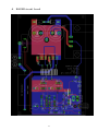
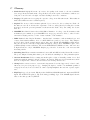
oneTesla User Manual
EvolutionWabbit Incorporated
July 24, 2012
1
Contents
1 Before You Begin...
4
2 WARNINGS
4
3 Introduction to Tesla Coil Operation
4
4 Summary of Circuit Operation
5
5 Kit Contents
6
6 Assembly Instructions
6.1 Driver . . . . . . . . . .
6.2 High-frequency Inverter
6.3 Gate Drive Transformer
6.4 Tesla Coil Secondary . .
6.5 Toroidal topload . . . .
.
.
.
.
.
.
.
.
.
.
.
.
.
.
.
.
.
.
.
.
.
.
.
.
.
.
.
.
.
.
.
.
.
.
.
.
.
.
.
.
.
.
.
.
.
.
.
.
.
.
.
.
.
.
.
.
.
.
.
.
7 Primary Coil
.
.
.
.
.
.
.
.
.
.
.
.
.
.
.
.
.
.
.
.
.
.
.
.
.
.
.
.
.
.
.
.
.
.
.
.
.
.
.
.
.
.
.
.
.
.
.
.
.
.
.
.
.
.
.
.
.
.
.
.
.
.
.
.
.
.
.
.
.
.
.
.
.
.
.
.
.
.
.
.
.
.
.
.
.
.
.
.
.
.
.
.
.
.
.
.
.
.
.
.
.
.
.
.
.
.
.
.
.
.
.
.
.
.
.
.
.
.
.
.
.
.
.
.
.
.
.
.
.
.
.
.
.
.
.
7
7
8
8
8
9
10
8 Assembly and Troubleshooting
10
8.1 Step 1: Verify Logic Functionality . . . . . . . . . . . . . . . . . . . . . . . . . . . . . . . . . 10
8.2 Step 2: Primary-only testing . . . . . . . . . . . . . . . . . . . . . . . . . . . . . . . . . . . . 10
8.3 Step 3: Spark testing . . . . . . . . . . . . . . . . . . . . . . . . . . . . . . . . . . . . . . . . . 11
9 Optimization
11
10 Maintenence
12
11 Conclusion
12
A EAGLE circuit board
13
B Schematic Diagram
14
C Glossary
15
D Copyright and Licensing
16
2
List of Figures
1
2
3
4
5
6
7
8
Simplified Tesla Coil Model . . . . . .
Simplified DRSSTC model . . . . . . .
Half-bridge Inverter . . . . . . . . . .
GDT Construction . . . . . . . . . . .
Secondary Dimensions . . . . . . . . .
Toroid Assembly . . . . . . . . . . . .
Pro/Ultra Kit Only: Toroid Assembly
Primary Dimensions . . . . . . . . . .
.
.
.
.
.
.
.
.
.
.
.
.
.
.
.
.
.
.
.
.
.
.
.
.
.
.
.
.
.
.
.
.
3
.
.
.
.
.
.
.
.
.
.
.
.
.
.
.
.
.
.
.
.
.
.
.
.
.
.
.
.
.
.
.
.
.
.
.
.
.
.
.
.
.
.
.
.
.
.
.
.
.
.
.
.
.
.
.
.
.
.
.
.
.
.
.
.
.
.
.
.
.
.
.
.
.
.
.
.
.
.
.
.
.
.
.
.
.
.
.
.
.
.
.
.
.
.
.
.
.
.
.
.
.
.
.
.
.
.
.
.
.
.
.
.
.
.
.
.
.
.
.
.
.
.
.
.
.
.
.
.
.
.
.
.
.
.
.
.
.
.
.
.
.
.
.
.
.
.
.
.
.
.
.
.
.
.
.
.
.
.
.
.
.
.
.
.
.
.
.
.
.
.
.
.
.
.
.
.
.
.
.
.
.
.
.
.
.
.
.
.
.
.
.
.
.
.
.
.
.
.
.
.
.
.
.
.
.
.
.
.
.
.
.
.
.
.
.
.
4
5
5
8
9
9
9
10
1
Before You Begin...
Congratulations on your purchase of a oneTesla kit! oneTesla is a coil designed to perform well, while being
simple for beginners to build, flexible, efficient, and cost-effective to maintain and repair. It is an ideal
introductory platform for beginning coilers, as well as an excellent Tesla coil for more advanced users seeking
a small, portable coil.
In the following text, bold indicates a technical term that can be found in the Glossary.
2
WARNINGS
1. Never touch the output of the Tesla coil; it is extremely dangerous and may cause serious injury or
death. High-frequency RF output can cause painful deep skin burns.
2. Users of pacemakers or other electronic medical implants should not use this kit. EMI emitted by the
coil may interfere with implant function, causing death.
3. Wear safety goggles at all times when operating the Tesla coil. Power semiconductors may overheat
and fail violently, causing a shrapnel hazard.
4. Energy storage capacitors on the board will remain charged for up to 5 minutes after powering down
the coil. Do not attempt to service the coil until sufficient time has passed. Furthermore, it is advised
to use a multimeter to measure voltage across the capacitors before servicing. Failure to do so may
cause serious injury or death.
3
Introduction to Tesla Coil Operation
A Tesla coil is an air-cored, resonant transformer. It develops a high voltage at its output terminal via a
combination of two mechanisms: transformer step-up action, and resonant rise across the output. Unlike a
standard transformer, a Tesla coil has no magnetic core. The benefits of this are twofold. Firstly, it reduces
the chances of secondary arc-over (there is no core to arc to). Even more importantly, the equivalent “volts
per turn” of a Tesla coil can be hundreds or thousands of volts per turn. Any magnetic material would
saturate at this many volts per turn, so air is the only option.
Figure 1: Simplified Tesla Coil Model
The AC source drives a primary coil at the resonant frequency of the secondary coil (modeled by L1, C1,
and R1). R1 represents the parasitic resistance of the secondary coil, and C1 is the intrinsic capacitance
between the windings of the coil, plus that of the topload. Because of transformer action, on the secondary
side it looks like we are driving the RLC tank with a higher voltage. Furthermore, because we are driving
the tank at its resonant frequency, C1 develops a high peak voltage (determined by the value of R1). It is
this peak voltage that determines the spark length.
Different Tesla coils differ in how the driving voltage across L1 is developed. In a spark gap Tesla coil,
it derives from the oscillations that occur after “pinging” a resonant tank circuit. In a classical solid-state
Tesla coil, it is a high-frequency DC-AC inverter with a peak voltage of perhaps 400V. However, with such
a low peak voltage (versus the 10KV+ of a spark gap coil), spark performance is hindered.
4
A double-resonant solid-state Tesla coil (DRSSTC) remedies this problem by putting a capacitor in series
with the primary:
Figure 2: Simplified DRSSTC model
The AC voltage source here is still a DC-AC inverter. It drives a LC tank at resonance, leading to
high voltages developed across L1 (as in a spark gap coil). Because of the phase difference between the
voltages across the tank capacitor and primary, the inverter always only sees, say, 400V across it. Because
of resonant effects, the inverter has to source tremendous current (since the current through the inverter
is VL1 /2πf L1 and we want VL 1 to be large). However, semiconductor power switches such as MOSFETs
and IGBTs are well suited to conducting very high pulsed currents (oneTesla uses IGBTs rated for 60A
continuous operation, but operates happily at over 300A).
In oneTesla, the inverter is implemented as a half-bridge:
Figure 3: Half-bridge Inverter
When S1 is closed, the load (primary circuit) sees V1 /2 volts across it. When S2 is closed, the load sees
−V1 /2 volts. The advantage of using a double-resonant circuit is that the transistors only need to be rated
for V1 volts. MOSFETs and IGBTs rated for 600V operation are quite common and can be cheaply obtained; MOSFETs rated for high primary voltages are extremely expensive and have non-ideal characteristics.
The transistors in the inverter have to carry upwards of 300A. In order to prevent the bridge from
overheating, it is necessary to pulse the inverter on and off using an “interrupter”. Furthermore, it is
necessary to insure that the inverter switches when the tank current is zero, to reduce switching losses in
the transistors. The control circuit, described in the next section, insures this.
4
Summary of Circuit Operation
The current transformer samples the primary current waveform, which is clamped by diodes D1 and
D2 to the 5V rail. The 1K power resistor insures the diodes do not have to carry excessive current. This
clamped signal is then fed into the input of IC1, a 74HC14, producing a buffered clock signal for the D-type
flip-flop, IC2. IC2 insures that the interrupter signal (which comes from the optocoupler) only turns off
the inverter at the zero crossings of the current waveform (which happen to be the edges of the clock signal
from the 74HC14).
The output of the 74HC14 also drives the inputs of IC3 and IC4, UCC37321/2 gate drive IC’s. A power
IGBT does not have an ideal gate; its gate has some capacitance which needs to be charged to operating
voltage. If we were to drive these gates directly with the output of the flip-flop, the gate capacitor would
behave like a short when uncharged, and draw enough current to destroy the IC. Instead, the UCC3732x
5
chips, which have high-power output stages capable of sourcing 9A for brief pulses, buffer the drive signal.
The gate drive transformer provides isolation for the high-side signal, which is referenced to the collector
of the low side transistor. This means when the high-side transistor turns on, its gate needs to be charged
to 355V with respect to ground. A transformer provides a convenient way to do this.
Diodes D3, D4 and capacitors C9 and C10 form a voltage-doubling rectifier to supply 340V to the halfbridge, for better spark performance versus undoubled rectified mains.
Now that you (hopefully) understand how a Tesla coil works, lets start building!
5
Kit Contents
Part
UCC37321
UCC37322
74HC14
74HC74
14-pin IC socket
8-pin IC socket
Toroidal Core
FGH60N60SMD
Trifilar 24AWG wire
2.5” OD PVC Tubing
3.5” OD PVC Tubing
Extruded heatsink
4-40 Screws
8-32 Screws
8-32 Nuts
Thermal Pad
1KOhm 5W Power Resistor
Current Transformer
1000 uF 250V capacitor
1000 uF 16V capacitor
1uF 100V capacitor
100 nF 50V capacitor
330 pF 100V capacitor
100KOhm 1/4W resistor
10KOhm 1/4W resistor
600 Ohm 1/4W resistor
200 Ohm 1/4W resistor
6.8 Ohm 1/4W resistor
LM7815 IC
LM7805 IC
Fiber optocoupler
3.5mm LED
2-pin jumper
3-prong AC jack
2.5x5.5mm DC jack
1N4148 diode
MUR460 diode
Inner tube
Aluminum tape
36 AWG magnet wire
Quantity
1
1
1
1
2
2
2
2
3’
10”
4”
1
2
2
2
2
1
1
2
3
10
1
1
1
1
1
1
2
1
1
1
2
1
1
1
2
2
1
1 roll
1 spool
6
6
Assembly Instructions
6.1
Driver
1. Install IC1, the 74HC14 inverter. To do so, install a 14-pin IC socket, then install the IC itself in the
socket. Be sure to take note of the location of the notch on the IC.
2. Install IC2, the 74HC74 flip-flop.
3. Install IC3, the UCC37321 gate-driver.
4. Install IC4, the UCC37322 gate-driver.
5. Install C1, a 100 nF capacitor.
6. Install C4, a 1 uF capacitor.
7. Install C5, a 1 uF capacitor.
8. Install C6, a 1 uF capacitor.
9. Install C7, a 1 uF capacitor.
10. Install C8, a 1 uF capacitor.
11. Install C11, a 1 uF capacitor.
12. Install C13, a 1 uF capacitor.
13. Install C14, a 1 uF capacitor.
14. Install C16, a 1 uF capacitor.
15. Install C17, a 330 pF capacitor.
16. Install R4, a 1Kohm resistor.
17. Install R5, a 10KOhm resistor.
18. Install R6, a 200Ohm resistor.
19. Install R7, a 600Ohm resistor.
20. Install R8, a 100KOhm resistor.
21. Install D1, a 1N4148 diode. Take care to note the polarity as indicated by the band on the silkscreen.
22. Install D2, a 1N4148 diode.
23. Install JP1, a 2-pin jumper.
24. Install the DC power jack PJ-037B.
25. Install the fiber optocoupler. Make sure the mounting pins are aligned with the holes in the board.
26. Install IC5, the LM7815 regulator.
27. Install IC6, the LM7805 regulator.
28. Install the 1KOhm, 5W resistor.
29. Install C2, a 1000 uF, 16V capacitor. Be sure to note the polarity!
30. Install C15, a 1000 uF, 16V capacitor.
31. Install C3, a 1000 uF, 16V capacitor.
7
6.2
High-frequency Inverter
Begin by tinning the traces running from the power jack to the bridge, and from the bridge to the tank
capacitor.
Then:
1. Install U3, a FGH60N60SMD IGBT.
2. Install U4, a FGH60N60SMD IGBT.
3. Install D3, a MUR460 diode. Be sure to note polarity.
4. Install D4, a MUR460 diode. Be sure to note polarity.
5. Install the current transformer.
6. Solder a 14 AWG jumper wire between the pads P1 and P2. The jumper should pass through the
center of the current transformer.
7. Install the 3-terminal AC inlet.
8. Install the 2-terminal terminal block for the output.
9. Install the CDE940 film capacitor.
10. Install C9, a 1000 uF, 250V capacitor. Be sure to note polarity.
11. Install C10, a 1000 uF, 250V capacitor.
12. Install R2, a 6.8Ohm resistor.
13. Install R3, a 6.8Ohm resistor.
14. Tape some polyamide tape over the bottom of the heatsink.
15. Place a piece of thermal pad on the tab of each IGBT, and screw the IGBT’s onto the heatsink using
the included 4-40 screws.
6.3
Gate Drive Transformer
Twist the three strands of trifilar wire together tightly, either by hand or with a drill. Mark one end of the
bundle with tape or a marker, and then wind 15 turns of the wire tightly around the toroidal core. Separate
the three separate wires and twist the ends together. Install the transformer in the board, taking care to
phase it properly as show in the following diagram:
Figure 4: GDT Construction
6.4
Tesla Coil Secondary
Carefully wind the included magnet wire on the included former to dimensions as show in the diagram below.
It is imperative that the turns to not overlap - even one crossed turn will cause catastrophic failure of the
coil. If you purchased the Pro/Ultra version of the kit, you may skip this step, as it comes with a pre-wound
secondary.
8
Figure 5: Secondary Dimensions
After winding the coil, you may optionally varnish it with clear enamel or polyurethane. This step is
highly recommended, as it increases the endurance of the secondary coil, but is not necessary for operation.
6.5
Toroidal topload
Begin by inflating the included inner tube. Inflate only until it is full enough to hold its shape; overinflating
may cause distortion or bulging in the tube. In particular, DO NOT inflate it to the pressures you would
find in a tire, as inner tubes are not designed for operation at full pressure outside of a tire.
Coat the inner tube and cardboard disk with aluminum tape. Use the included spoon to smooth out any
wrinkles in the tape.
Using the included sandpaper, sand the enamel off 2” of the loose wire on one end of the secondary.
Assemble the toroid and secondary as shown below:
Figure 6: Toroid Assembly
Purchasers of the Ultra version of the kit only: you should have recieved a spun aluminum toroid in your
kit. You should have also recieved a plastic end cap and mounting hardware for this toroid. Sand the enamel
off the end of the winding as above, and then assemble the secondary as shown in the following diagram:
Figure 7: Pro/Ultra Kit Only: Toroid Assembly
9
7
Primary Coil
Wind the primary coil using 12 AWG wire according to the following diagram:
Figure 8: Primary Dimensions
8
Assembly and Troubleshooting
Now comes the fun part! The coil is nearly assembled, but don’t connect the primary coil or plug in the
main power just yet!
8.1
Step 1: Verify Logic Functionality
1. Plug the 19V wall adapter into the power jack on the board.
2. Plug the wall adapter in. Verify that the both LED’s are on. If not, confirm that they are installed
with the correct polarity, that they are properly soldered, and that the power jack is properly soldered.
3. Connect the interrupter to the driver using the included fiber optic cable. At this point, if you have an
oscilloscope, verify that pin 3 on both gate drive IC’s are low duty-cycle square waves of a few hundred
hertz. If no signal is present, makes sure that the ON time setting on the interrupter is not zero.
4. If you do not have an oscilloscope, raise the pulsewidth to a nonzero setting and listen for a faint
buzzing sound from the GDT.
5. Verify that none of the IC’s are hot to the touch. Hot voltage regulators are normal.
8.2
Step 2: Primary-only testing
1. Connect the primary to the driver by screw the end-terminals to the terminal block.
2. With the logic unplugged, plug in the main power cord. Verify that nothing happens.
3. UNPLUG the main power, and wait for the bus capacitors to bleed (approximately 5 minutes).
4. Plug the logic in. MAKE SURE THAT THE MAIN POWER IS UNPLUGGED AND THE BUS
CAPACITORS ARE DISCHARGED!!!
5. If you have not done so already, connect the interrupter to the driver using the fiber cable.
6. Set the switch on the interrupter to “Manual” mode and turn the ON time knob to zero.
7. If you have a variac, complete the next steps with the main power plugged in to the variac.
8. Plug the main power cord in.
9. Turn up the ON time knob slightly. You should hear a faint buzzing sound from the primary.
10
10. If you own an oscilloscope, you can confirm that the primary current waveform is behaving appropriately. Make a current transformer by winding 50 turns of wire on the included toroidal core and
soldering a 3Ohm resistor across the loose ends. Feed the primary wire through the center of the toroid,
and ’scope the voltage across the resistor. It should be a clean sinusoid of steadily rising amplitude.
11. If you do not hear a buzzing sound from the primary, swap the positions of the UCC37321 and
UCC37322.
12. If no output is present, check for broken solder joints in the controller. Do not replace the transistors,
except as a last resort - it is exceedingly unlikely that brand new IGBT’s will be damaged.
8.3
Step 3: Spark testing
1. Center the secondary inside the primary, feeding the loose wire at the bottom through.
2. The AC power jack has a tabbed ground terminal. At this point, use some sandpaper to remove the
enamel from the loose (non-toroid) end of the secondary, and solder (or alligator clip) it to the ground
tab as you feel appropriate.
3. Unplug the main power cord.
4. Plug in logic.
5. Connect the interrupter, setting ON time to zero.
6. Plug in the main power cord, making sure the ON time is still zero.
7. SLOWLY turn up the ON time knob. There should be visible discharge at a very low setting.
8. If no sparks appear, DO NOT increase the ON time further. First, reverse the positions of the UCC gate
drive IC’s. If that does not work, check for loose solder connections, incorrectly placed components, or
backwards components (in the case of diodes and electrolytic capacitors). Also, verify that the GDT
is connected appropriately (note the position of the marked wires!).
9
Optimization
At this point you should have a functioning Tesla coil. If built according to the instructions, you should be
getting at least 15” sparks with the ON time turned to 100 uS.
Optimizing oneTesla is fairly straightforward. Add or remove primary turns as necessary, in order to
achieve maximum performance. The optimal point is probably no more than half a turn away in either
direction from the “stock” configuration.
Note that it is common for tuning parameters to change after mounting or moving the coil to a different
location. This is caused by the secondary capacitance values (which are parastic capacitances to ground)
changing.
If you have an oscilloscope, you can tune the coil with a ’scope as follows:
1. Set up the primary and secondary exactly as they will be set up in final operational conditions. This
means that the secondary should be installed and grounded, and the toroid should be installed.
2. Connect the positive lead of a signal generator to the toroid. Set the vertical resolution of the oscilloscope to 50 mV/div. Connect the ’scope probe to a wire of around 30mm long (you can leave the
ground clip of the signal generator and oscilloscopes unconnected).
3. Set the signal generator to generate a sine wave of about 225 KHz. The oscilloscope should display a
sine wave.
4. Sweep the frequency of the signal generator from 190 KHz to 260 KHz. The point at which the
amplitude of the ’scope trace is maximum is the resonant frequency of the primary+secondary setup.
11
5. Connect the driver board to the primary coil as described in “Spark Testing” above. Make sure there
is a current transformer installed on the primary (as described in “Primary only testing”). Power on
the coil, preferably with a variac if you have one. ’scope the voltage across the current transformer,
and examine the frequency (of the sinusoidal oscillations). If this frequency is lower than the resonant
frequency measured in the previous step, remove primary turns. If it is greater, add primary turns.
10
Maintenence
To insure a long lifetime, keep the ON times low and the OFF times high for a given spark length. Too
low of OFF time may lead to rapid failure due to transistor overheating. Too high of an ON time may lead
to either catastrophic failure from overcurrent, or slow degradation of the transistors due to long-term abuse.
If you should ever damage the transistors, replacement is straightforward and will cost around $10.
Simply:
1. Unscrew the heatsink from the transistors.
2. Clip the leads on the transistors and remove the damaged ones.
3. Desolder the individual leads that remain in the board. Do not use too high of a iron temperature or
overheat the board, as it may damaged the traces.
4. Install new transistors. Then, reinstall the heatsink, taking care to not forget the silicone thermal
pads.
11
Conclusion
And that’s it, folks! We hope you enjoyed building our kit! Be sure to check our website, http://www.onetesla.com,
for updates and exciting new products.
For those of you into the design aspects of the coil, EAGLE PCB and schematic files are available on our
website as well.
12
A
EAGLE circuit board
13
B
Schematic Diagram
14
C
Glossary
1. Tank Circuit A high-Q LC circuit. “Q” refers to the quality of the circuit; i.e. the rate at which it
loses energy. In an ideal tank circuit, energy sloshes between the capacitor and inductor, without ever
being lost or used. It can be thought of as water sloshing between two containers.
2. Pinging Colloquial term for stepping the capacitor voltage in an LC tank circuit. This results in
sinusoidal oscillations at the resonant frequency.
3. Topload The often toroidal, sometimes spherical object connected to the secondary in a Tesla coil.
Its duties are twofold: it increases the capacitance of the secondary (thereby lowering the resonant
frequency), and it also prevents premature breakout from the Tesla coil by “smoothing” the electric
field out.
4. MOSFET Metal Oxide Semiconductor Field Effect Transistor. A voltage controlled transistor with
an insulated gate terminal. A power MOSFET loses energy proportional to I 2 Rds,on , where I is the
current it is carrying, and Rds,on is the on-state resistance of the transistor.
5. IGBT Insulated Gate Bipolar Transistor. Another kind of transistor, with an insulated gate and
on-state characteristics similar to those of a BJT. IGBT’s are purely a power device. They dissipate
as I log I, where I is the forward current, and are hence more efficient that MOSFETs at high current.
They are also far more friendly to high (300V and higher) voltages, where MOSFETs begin to have
prohibitively high on-state resistances. The reason all DRSSTCs use IGBTs is because of the low losses
at high currents; not only do MOSFETs dissipate proportional to I 2 , their Rds,on also increases with
increasing current.
6. Switching Loss When a transistor transitions between ON and OFF, it briefly behaves like a resistor.
The power dissipated during this resistive period is called the switching loss of the particular system.
7. Current Transformer Used for sensing current through a conductor. It usually consists of a toroidal
transformer with the primary being the conductor in question. This acts as a 1:N transformer, and if
there are I amps in the conductor, the CT behaves as a N I amp current source.
8. Clamp In this context, it refers to a waveform being truncated at a fixed upper and/or lower bound.
Often used for protection purposes (e.g. clamping the input to an IC to its maximum permitted
voltages). In our case, however, it is used to turn a very high-amplitude sine wave into a pseudo-square
wave.
9. Flip-Flop A type of logic circuit. Flip-flops take a DATA and CLOCK signal and output an OUTPUT
signal. The OUTPUT is updated only at the rising (or falling) edges of the CLOCK signal, when it
takes on the value specified by INPUT.
15
D
Copyright and Licensing
The contents of this document, of other documents included in this kit, and of the schematics and PCB
reference files found on our site and in the preceding Appendices, are all licensed under the GNU Free Documentation License. Full content’s of this license can be found on the web, but to put it briefly, you are free
to disseminate these files or derive work from them, so long as your work is licensed under the GNU FDL.
After all, every project can be improved, and you might be able to improve ours!
We encourage you to spread the documentation and schematics - it improves our business, but more
importantly, might also inspire aspiring coilers everywhere to build a DRSSTC. And the more coilers, the
merrier, right? :)
16