1
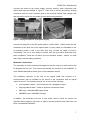
DRSSTC 4.2 User Manual
IT IS ESSENTIAL THAT YOU READ THIS DOCUMENT FOR
SAFE AND RELIABLE COIL OPERATION.
REV 1.2 21/11/2010
DRSSTC4.2 User Manual
Contents:
Contents:................................................................................................................... 1
Product Description: .................................................................................................. 2
Parts Included: .......................................................................................................... 3
Coil Assembly: .......................................................................................................... 4
Coil location: ...................................................................................... 4
Breakout point: ................................................................................... 5
Cable connections:............................................................................. 6
Modulator connections: ...................................................................... 7
Safety and Operating Considerations: ....................................................................... 8
Essential operating guidelines: ........................................................... 8
Electrocution risks: ............................................................................. 8
Interference and damage to electronics:............................................. 9
Fire hazards: ...................................................................................... 9
Health hazards: .................................................................................. 9
Legalities: ......................................................................................... 10
Coil Operation: ........................................................................................................ 11
Essential checks before operating: ................................................... 11
Essential tests before applying modulation:...................................... 11
Considerations for extended operation: ............................................ 12
Maintenance: ................................................................................... 12
Trouble Shooting: .................................................................................................... 13
If a flash-over is observed: ............................................................... 13
Arcing at the torroid interface: .......................................................... 14
Power supply fault indications: ......................................................... 14
Tuning: ............................................................................................. 14
Guarantee: .............................................................................................................. 15
It is advised that you read and understand all aspects of this manual before use.
Improper use of the device may cause personal injury, death, fire or criminal
proceedings. Brightarcs can not be held responsible for any resulting losses as a
result of using their product. The user is solely responsible for the safety of
themselves and others, it is essential that they read and familiarise themselves with
this document.
1
DRSSTC4.2 User Manual
Product Description:
Brightarcs DRSSTC 4.2 is a musically modulated highly advanced double resonant
solid state tesla coil. This section briefly summarises how the device works.
Tesla coils operate using the phenomenon of electrical resonance in which energy is
transferred between magnetic field storage and electric field storage. In the case of
the secondary, the magnetic field is created around the solenoid coil of the
secondary windings and the electric field is stored as charge on the capacitance of
the round torroid (see Figure 1). The resonance occurs at the secondary resonant
frequency. The primary winding resonates with a separate large capacitor located
within the power supply at the primary resonant frequency. The primary circuit is
driven at its resonant frequency causing energy to accumulate in the circuit. This
circuit is coupled by transformer action to the secondary and in turn drives the
secondary circuit at the same frequency. If the two frequencies are similar then large
voltages are induced on the torroid, causing the air around it to undergo electrical
break-down. The resonant frequency of the secondary drops as the plasma formed
by the break-down of the air forms a streamer. The primary frequency is tuned to
slightly below the secondary and this frequency gap reduces the chance of
breakdown. When breakdown does occur, the streamer growth lowers the secondary
resonant frequency and the gap decreases causing much higher voltages on the
secondary. This ensures maximum energy is delivered to the streamer, resulting in a
longer arc forming between the torroid and the surroundings.
The breakdown of the air causes rapid heating of the region around the streamer.
This causes sudden thermal expansion resulting in a loud noise in the same way
thunder is caused. The power supply allows reproduction of the breakdown many
times per second and this allows a musical tone to be played. For example, breaking
down the air 440 times per second causes the musical note 'A'. The modulator
changes the breakdown repetition rate and intensity to recreate the musical input.
The modulator can only try to approximate the musical input since the output will
always be a pattern of loud 'clicks' caused by the breakdown events.
Brightarcs has created the DRSSTC4.2 as a simple and robust way to demonstrate a
musical DRSSTC.
2
DRSSTC4.2 User Manual
Parts Included:
The DRSSTC4.2 is supplied as the 8 components shown in Figure 1. If any of these
components is not included in the packaging then contact Brightarcs.
Figure 1. Coil components
The kit consists of:
1 x Torroid of light weight aluminium ducting and polystyrene.
1 x Trolley of light weight MDF and plywood construction on plastic castors.
1 x Pre-assembled primary and secondary coil combination.
1 x DRSSTC4.2 power supply.
1 x 5m switched IEC cable with UK plug socket (unless alternative requested).
1 x 10m digital optical cable.
1 x Digital modulator, cables and batteries*.
3 x Breakout points of 2mm copper wire.
1 x Documentation pack.
The parts supplied should not be exchanged for other similar parts because this
could create a fire or electric shock risk. The next section covers assembly of the coil
components.
* The modulator is under continuous development and a separate document will contain a
detailed description of the modulator version supplied.
3
DRSSTC4.2 User Manual
Coil Assembly:
Coil location:
Setting up the tesla coil has been made as easy as possible by the modular
construction. Choose a location clear from any objects which could catch fire or be
damaged by the coil. Ensure that the ceiling is 3m or more from the floor and that
there no sharp objects close to the base of the coil. If the coil is operating outdoors
then ensure there is no chance of rain reaching the coil. If the coil is operating
indoors then adequate ventilation must be present. Assemble the coil, torroid and
power supply onto the trolley, taking care to observe the clearances required for safe
operation (Figure 2). The assembly should look like Figure 3. The torroid is marked to
show which side must be downward facing.
Figure 2. Required clearances for operation
Figure 3. Correctly assembled coil on the trolley
4
DRSSTC4.2 User Manual
The operator should ensure the coil is stable and that there are no strong gusts of
wind or other causes for the coil to topple over. Do not place the coil in fire escape
routes or adjacent to doors which might be opened. It is recommended that a plastic
barrier be used to protect any observers from the coil. It is the operator's
responsibility to ensure that all potential risks are assessed before turning the coil on.
A sample risk assessment can be obtained from Brightarcs.
Breakout point:
The coil must be operated with a breakout point since this effectively limits the
stresses experienced by the insulation between the primary and secondary windings.
Operation without a breakout point will lead to unpredictable behaviour and
destructive flash-overs which will destroy the windings. Suitable wire breakout points
are supplied and one or more should be positioned on top of the torroid pointing
outwards as shown in Figure 4. The breakout points can be used to direct the
streamers in a way that gives a better plasma display from the coil. More breakout
points create shorter arcs but offer superior audio performance.
Figure 4. Correct breakout point orientation
5
DRSSTC4.2 User Manual
Cable connections:
The power supply has several connection points and indicators detailed below.
Figure 5. Front of power supply
Figure 6. Rear of power supply
Part
Description
Power inlet
IEC power inlet 220-240 VAC 50/60Hz. Only use the power cable
provided.
Optical input
Connection to the modulator via optical cable. Only use the fully
unwound plastic cable provided (Note: Not SPDIF).
Over current breaker
Thermal over current circuit breaker. The insert pops out in the
event of over current. Do not reset with power connected.
Power indicator
Green LED to indicate the main board has power.
Fault indicator
Red LED to indicate input surge, under voltage, over temperature
and over current.
Medium voltage output
High frequency coil output at ~340 VAC. Connect to the primary
lead without silicone insulation reinforcement.
High voltage output
High frequency high voltage coil output ~12 kVAC. Connect to the
primary lead with silicone reinforcement.
Earth connection
Connect to the secondary earth lead. Enclosure is earthed.
Heat sink
The heat sink to cool the power transistors and enclosure base.
Serial number
The power supply serial number.
Enclosure
Note: Opening the enclosure will void the warranty.
Table 1. Power supply parts summary
6
DRSSTC4.2 User Manual
Connect the wires for the power supply, primary winding, earth connection and
optical lead input as detailed in Figure 7. Take care to ensure the primary winding
connection with the extra insulation goes to the terminal marked ‘high voltage’ and
that the power lead is not connected to the mains during assembly.
Figure 7. Wiring connections of the power supply
Connect the plug side of the IEC power lead to a 230V (220V - 240V) socket and the
modulator to the other end of the optical cable. In many cases it is desirable to use
an extension cable, if this is the case then fully un-wind the cable to avoid it
overheating. The coil is now ready to operate once the pre-checks and tests have
been completed. These are covered in the coil operation section - ensure you read
and comply with the safety guidelines.
Modulator connections:
The modulator is under continued development and the most up to date version will
be shipped with the coil. This section summarises the function of the modulator. A
more detailed description will be given in the modulator manual.
The modulator connects to the end of the optical cable and consists of a
microprocessor with an interface to the source of the modulation and an optical
output to the coil. The interface may be one or more of the following:
•
Low impedance audio - Sound card line-out / headphone output
•
High impedance audio - Guitar or dynamic microphone levels
•
MIDI input - Standard MIDI signal levels
•
USB/MIDI input - USB MIDI interface
In addition, the modulator will have a 'test mode' used to check for correct coil
operation before applying full power in order to prevent problems with flash-over and
other unpredictable operation.
7
DRSSTC4.2 User Manual
Safety and Operating Considerations:
This section of the manual covers the safety risks that are present when operating a
Tesla coil. The operator should adhere to the following points which are explained in
more detail throughout this section.
Essential operating guidelines:
1) Never unplug during operation (this removes the ground connection).
2) Never approach the coil when it is powered.
3) Always wait 5 minutes before unplugging the coil after switching it off.
4) Always use only the specified voltage of 220V - 240V (NO VARIAC!).
5) Only operate within ambient temperatures between 5°C and 30°C.
6) Always operate the coil from a safe distance of > 3m.
7) Always place the torroid on top of the coil.
8) Always place at least one breakout point on top of the torroid.
9) Never operate near flammable materials.
10) Never operate in condensing humid environments.
11) Never operate if the secondary is damp.
12) Always remove dust from the secondary using a duster before use.
13) Always be ready to turn off the coil quickly.
14) Always ground the coil via the plug (do not remove this connection).
15) Only allow arcing to grounded objects and preferably do not arc continuously.
Electrocution risks:
A tesla coil creates many thousands of volts in order to produce impressive plasma
displays in the surrounding air. The voltage produced has two components, the
alternating current (AC) and the direct current (DC) parts.
The DC component arises as a result of the capacitance of the coil discharging into a
grounded object. If this current flows into a person, it will cause a sensation of pain
similar to a Van de Graaff generator. The Tesla coil can repeat this sensation at over
500 times per second; This results in a very painful shock and lasting burns to the
surrounding tissue. Users who wear pacemakers or electronic health maintenance
devices should never approach a coil. Even healthy adults occasionally suffer
cardiac arrest as a result of electric shocks; Brightarcs advice is to NEVER
APPROACH AN OPPERATING COIL or attempt to draw an arc to a hand held
object.
8
DRSSTC4.2 User Manual
The plastic coil formers (particularly of the secondary winding) will accumulate
charge during operation and this will result in a residual charge building up on the coil
over the several minutes after turn off. If the device is unplugged then small static
shocks will result when handling the coil; To avoid this, leave the coil plugged in with
the switch in the off position for 5 minutes before unplugging (or ground the coil
externally before handling).
An operating coil may cause grounded and un-grounded objects to produce small
shocks when touched. This is usually because the person is standing between the
coil and a grounded object and hence offering a path for the high frequency AC
current. To avoid this, the person could either ground themselves by holding a
grounded object or (preferably) move to the other side of the object so that they are
no longer presenting a path to the AC current (i.e. Not between the coil and a
grounded object). Placing a grounded shield around the coil to make a faraday cage
is an effective way to prevent indirect shocks like this.
Interference and damage to electronics:
The high frequency AC electric field can pose a serious problem to other electrical
equipment. The AC field around the coil WILL cause damage to electronic devices
such as: Computers, telephones, alarm systems, smoke detection systems,
televisions, transmitting/receiving equipment, game consoles, appliances and any
circuit containing electronic components. It is recommended that the coil is operated
away from these items by a separation of at least 10m. The AC component will also
travel along extension cables and through ring mains in buildings causing damage to
devices at greater distances. It is recommended that sensitive devices are unplugged
before operation.
Fire hazards:
The plasma created by the coil is extremely hot, particularly when arcing to a
grounded object. Contact with a flammable material will cause instant flames. In
addition, flammable gas will also be immediately ignited and operation near a
potential gas source should be avoided.
Health hazards:
Brightarcs have found no evidence that observing the coil will cause injury. People
with sensitive eyes should be aware that the bright flashes my cause discomfort.
Furthermore, PEOPLE WITH PHOTOSENSITIVE EPILEPSY SHOULD NEVER
WATCH THE COIL.
9
DRSSTC4.2 User Manual
There is no evidence that the high frequency electric field can cause damage to living
tissue. A safe observation distance is 3m or more. A non-conductive barrier around
the coil can be used as an effective way to limit the proximity of the audience to the
coil. Some sort of barrier must be in place to ensure people do not approach the coil.
Also note the required clearance above the device to reduce the chance of arcing to
the ceiling.
The sound that the coil produces is extremely loud and can result in tinnitus after
long exposure. Ear protection is essential in some installations depending on the
acoustics. Always warn observers of the loud noises before switching the coil on to
avoid trauma.
Legalities:
THIS COIL PRODUCES INTERFERING ELECTROMAGNETIC RADIATION if
operated outside a grounded cage enclosure. In this case the device will be breaking
the law according to broadcasting regulations in most countries. However, Brightarcs
has not heard of a single incidence where legal action by the FCC or similar
governing body has been taken. Please remember this when dealing with complaints
by amateur radio enthusiasts using old fashioned radio equipment who will be able to
hear the coil on their radios over large distances. Modern radio equipment such as
WiFi, Bluetooth, GSM phones and communication radios are unlikely to be affected.
10
DRSSTC4.2 User Manual
Coil Operation:
Tesla coils can be unreliable if improperly operated. Please adhere to the following
section to ensure safe, reliable and long life operation.
Essential checks before operating:
Before applying power to the coil check the following referring to the Coil Assembly
section:
1) The power supply is wired up correctly.
2) The torroid is in the correct orientation on top of the secondary.
3) The breakout point is located properly.
4) The coil is stable and not likely to topple over.
5) There are no conductors that could pass current outside the exclusion zone.
6) There are no objects left adjacent to the coil or on the trolley.
7) There is no sensitive equipment within 10m of the coil.
8) There are no flammable objects within 3m of the coil.
9) There is no chance that a person or animal might approach the coil.
10) Suitable warnings have been given to all others present.
11) Suitable personal protective equipment has been supplied to the observers.
Essential tests before applying modulation:
(refer to the modulator operating manual throughout this section)
The modulator should be disconnected from the optical lead and configured for
'TEST MODE'. The IEC power lead should be connected to the power source and
the switch closed in order to apply power to the power supply. The LEDs should both
turn on and after 1 second the fault (red) LED will turn off. Connect the modulator to
the optical lead. This will cause the coil to pulse at relatively low power, be ready to
disconnect the modulator in case unexpected operation occurs.
The test mode should continue for at least 30 seconds during which time the
operator should watch the base of the coil for flash-over. The operator should also
check for arcing near the base of the coil and at the interface between the torroid and
the secondary. If no flash-over or arcing occurs for 30 seconds then the modulator
can be switched to a normal modulation mode. It is recommended that the operator
continuously monitors the coil for flash-over whenever it is operating and be ready to
turn off the coil. If a flash-over occurs at full power output then the secondary winding
is likely to be rapidly and permanently damaged due to burning of the insulation.
11
DRSSTC4.2 User Manual
Considerations for extended operation:
The DRSSTC4.2 is designed to operate at moderate power output for up to
10 minutes. If the coil is used for more than this time or if the power level is high
then the power supply will overheat. This occurs at a heat-sink temperature of 45°C.
The power supply will not allow further modulation until it returns to less than 35°C. In
addition, the secondary winding temperature may become a burn hazard reaching
more than 100°C when subjected to continuous high power levels. The power supply
can be powered for the cool down period. This has the benefit of forcing air around
the internal components which decreases the cool down time. The stresses to the
power supply during the overheating condition will seriously reduce the life
span of the device. Do not attempt to increase the heat-sink capacity of the
device, this will only further stress the internal components and probably cause
device failure.
Maintenance:
There is little maintenance required to operate the DRSSTC4.2. The filters on the
power supply should be cleaned if they become clogged with dust. The secondary
winding should be kept dust free by wiping with a cloth. The static build up on the
secondary will attract dust which could cause a flash-over to occur.
12
DRSSTC4.2 User Manual
Trouble Shooting:
This section covers the most commonly observed problems encountered during coil
operation and offers advice on how to resolve them.
If a flash-over is observed:
Flash-over is when the coil streamers start at the base of the coil and move along the
surface of the secondary as illustrated in Figure 8. The most likely cause of a
flashover is an incorrectly located or missing breakout point.
Figure 8. Flash-over showing the base of the coil and streamer
Sharp objects around the coil (even blades of grass), dust on the secondary, a
shifted primary winding or other changes to the Tesla coil may also lead to flashover. Do no place any object within the zone shown in Figure 9. Flash-overs can also
be caused if the primary has slid up the coil. Slide it back down carefully so that it is
level with the base of the coil.
EXCLUSION ZONE
Figure 9. Exclusion zone
13
DRSSTC4.2 User Manual
If sparks are observed near or around the base of the coil, switch off modulation
immediately to avoid damaging the secondary. Locate and remove the cause and
resume operation. Occasionally, a coil may be damaged by a flash-over and
removing the cause in this case will not fix the problem. The coil will need repairing.
Flash-overs should NEVER occur; If even a small spark is observed near the base of
the coil, switch off and investigate the cause. A special test mode is included with the
modulator to test for flash-overs before applying full power.
Arcing at the torroid interface:
The torroid contacts the coil by a copper contact located at the top of the secondary
and arcing may result at this connection if there is a poor connection. It may be
desirable to permanently affix the torroid to the coil and this can be done using an
adhesive.
Power supply fault indications:
If there is a power supply fault it can be identified as follows:
Symptom
Cause
Action
No power indicator on
No power is present.
Check socket / extension
socket.
lead is working.
Power supply fan turns on
The power supply has been
Return to Brightarcs for
but no LEDs.
damaged.
repair.
Fault LED does not turn off.
Over temperature or
Allow to cool or check supply
insufficient voltage.
voltage.
No sparks, can hear quiet
Missing breakout point, bad
Check coil set up.
modulation sounds.
connection or damaged coil.
No response from the coil at
No optical connection link.
all and can see modulation
Check optical cable
connection for dirt.
pulses on optical link.
No modulation pulses.
The modulator is not working.
Check the modulator manual.
Poor spark length.
Tuning shifted.
See next section.
Table 2. Fault finding
Tuning:
This coil is self tuning within a wide range and will not normally require any
adjustment. However, if operated in an enclosed space, the resonant frequency of
the coil may drop sufficiently to cause a reduced spark output. If this occurs, operate
the coil in a less enclosed space. More experienced users might try to alter the coil
turns ratio (by adding or removing primary turn). It should be noted here that this will
void the guarantee if not carried out either by or under instruction from Brightarcs.
14
DRSSTC4.2 User Manual
Guarantee:
The guarantee covers all aspects of the electronic power supply assembly for 6
months or 300 hours of operation, whichever is sooner. The guarantee is for the
repair of the power supply and return to the customer (or refund). The guarantee is
only valid if the product is used within the operating conditions defined in the
operation section. Any attempts to open the case will invalidate the warranty.
To make a claim, the ENTIRE product must be returned in adequate packaging. The
original packaging is preferred (the secondary must be adequately protected for
postage). The guarantee only covers the secondary winding during initial shipping
due to its fragile nature. In the case of a damaged secondary coil, contact Brightarcs
to purchase a replacement or arrange a repair.
15