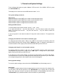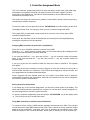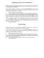
1
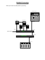
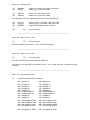
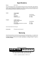
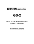
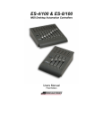
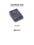
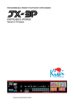
KENTON electronics
GS-8
MIDI Guitar Effects Switcher
User Instructions
Introduction By Arthur Dick, session guitarist.
At last, an affordable unit which enables you to control all your effects (pedals and MIDI) as well as
amplifier switches (channel/overdrive/graphic etc.) without having to do a tap-dancing routine each
time a new sound is required. The GS-8 is wonderfully flexible, allowing you to tailor make your
own system - it is the key to managing your guitar sounds. No more signal loss either; when a
circuit is not enabled, the signal path is clear. For playing live or in a studio, the GS-8 makes your
set-up work for you freeing you to get on with your playing.
If this was a household appliance, every home should have one!
Setting Up
MIDI Connections
The GS-8 must be connected to your MIDI set-up. Using a standard MIDI cable, connect one end
into the MIDI Out of your MIDI effects processor or other MIDI device, and plug the other end into
the MIDI In of the GS-8. Connect the MIDI Thru on the GS-8 to the MIDI In of any other MIDI
device if necessary.
Pedal Loop Connections
Connecting your guitar and amplifier;
Connect the output from your guitar to the input `FROM GUITAR` on the GS-8.
Connect the output `AUDIO TO AMP` on the GS-8 to your amplifier or mixer.
To connect each pedal to the GS-8;
Connect the pedal output to the input `FROM PEDAL #1` on the GS-8, and connect the pedal input
to the output `TO PEDAL #1` on the GS-8.
Do the same for each of your other pedals, to each pair of pedal connections on the GS-8.
To connect the GS-8 to the foot-switch inputs;
Connect the outputs `TO AMP A (/B)` to the foot-switch inputs on your amplifiers or A/B ampswitcher box.
If pedal loops 5 or 6 have been configured as foot-switch controls, use the `TO PED #5 (6) / AMP D
(C)` output to control the foot-switch input.
The Three Edit Modes
Switching On
When you first switch on the GS-8, it will momentarily display the software version number, then
revert to Patch Edit Mode, displaying the current patch number (default patch 1).
Loading factory defaults;
If the unit is switched on whilst holding down both the `+` and `-` keys, the display will read `Fd`
indicating that the GS-8 has been reset and the factory defaults loaded into the memories.
The GS-8 has two edit modes as indicated by the LED bars `PATCH/CHANnel`;
When the green LED next to `PATched` is on, the GS-8 is in patch edit mode.
When the yellow LED next to `CHannel` is on, it is in Channel/System edit mode.
There is a third special edit mode called Controller Assignment Mode which is described later in the
manual.
A red dot will flash on the right of the display to indicate when the GS-8 is receiving MIDI data
(except MIDI clock messages).
1, Channel and System Settings
To be in Channel edit mode, the yellow `CHannel` LED must be lit. If the `PATch` LED is lit, press
the `PATCH/CHAN` key.
The display will now show the current MIDI channel number 1 to 16.
The system settings consist of;
MIDI channel
Whether foot-switch control AMP A is a normal or momentary type control
Whether foot-switch control AMP B is a normal or momentary type control
Whether Pedal Loop #5 is configured as a foot-switch control
Whether Pedal Loop #6 is configured as a foot-switch control
Editing the MIDI channel;
To edit the MIDI receive channel number, use the `+` and `-` keys.
If you press and hold the `+` key, then also hold the `-` key, the channel number will increase
faster. If you press and hold the `-` key then also hold the `+` key, the channel number will
decrease faster.
If you try to go past 16, the channel number will `wrap-round` back to channel 1. The opposite also
applies.
Changing foot-switches from normal to momentary type;
To change the foot-switch outputs `AMP A` and `AMP B` from normal to momentary, press and
hold the AMP A/B keys till the orange LED by `MOMentary` lights. To change to output back to a
normal foot-switch control, again, press and hold the AMP A/B key till the LED is off.
Changing pedal loops 5 or 6 to foot-switch controls;
To change pedal loop number 5 and 6 to act as foot-switch controls, press and hold the
PED#5(6)/AMP C(D) keys till the yellow LED by `AMP` lights. To change back to pedal loopers,
again, press and hold the key till the LED is off.
If you change any of the system settings, you will see a red dot appear in the centre of the display.
This shows that one or more of the settings has been edited and not yet stored. If you revert which
ever setting/s changed back to their original value, the dot will disappear.
Storing system settings;
To store the system settings, press and hold the `PATCH/CHAN` key till the display reads `st`.
Sticky keys;
If a channel or system setting has been changed (and the red dot in the centre of the display is lit),
you will notice it will take two presses of the `PATCH/CHAN` key to change back to patch edit
mode. This `sticky key` function is so that the GS-8 remains in Channel/System edit mode if the
`PATCH/CHAN` key is pressed and held to store the channel or system settings.
2, Patch Edit Mode
Selecting patches;
To be in patch edit mode, the green `PATch` LED must be lit. If the `CH` LED is lit, press the
`PATCH/CHAN` key.
The display will now show the current patch number 1 to 128.
As the GS-8 only has a two digit display, a special method is employed to display numbers larger
than 99. When displaying numbers above 99, the following format is used :a dash " - " at the bottom of the left-hand display = 100+
a dash " - " in the middle of the left-hand display = 110+
a dash " - " at the top of the left-hand display = 120+
For example, supposing the display reads " - 7 "
if the dash is at the bottom, this means 107
if the dash is in the middle, this means 117
if the dash is at the top, this means 127
Note, that no values above 128 are used.
Select a patch number from 1 to 128 by pressing the `+` and `-` keys.
If you press and hold the `+` key, then also hold the `-` key, the patch number will increase faster. If
you press and hold the `-` key then also hold the `+` key, the patch number will decrease faster.
If you try to go past 128, the patch number will `wrap-round` back to patch 1. The opposite also
applies.
As you change patches you will see the orange LEDs turn on or off indicating which effects pedals
or foot-switches are active.
The relays will not actually switch (i.e. the patch will not physical change your set-up) till you
release the `+` or `-` key. This is to stop the relays from frantically trying to switch as you scroll
through patches to get to the one you need.
When you release either the `+` or `-` key, you will hear the relays click, changing your set-up.
Editing patches;
You can manually switch on or off any of the pedal loopers or foot-switches by pressing the
relevant keys.
If you change any of the patch settings, you will see a red dot appear in the centre of the display.
This shows that one or more of the settings has been edited and not yet stored. By changing the
settings back to their original values, the dot will disappear (now indicating the patch is unaltered).
Storing patches;
To store the patch settings, press and hold the `PATCH/CHAN` key till the display reads `st`. The
yellow `PAT` LED will be lit.
Sticky keys;
If a patch has been changed (and the red dot in the centre of the display is lit), you will notice it will
take two presses of the `PATCH/CHAN` key to change to Channel/System Settings Mode. This
`sticky key` function is so that the GS-8 remains in Patch Edit Mode if the `PATCH/CHAN` key is
pressed and held to store the edited patch settings.
The pedal loopers 5 and 6 can be configured to be foot-switchers in this mode as previously
described, although this should not be necessary once you have configured your set-up. The footswitchers A and B can be changed from normal to momentary foot-switch configuration as
previously described, but once again, this should not be necessary once you have configured your
set-up. These settings are not stored when an edited patch is stored. As these are system settings,
you must be in Channel/System edit mode (orange `CH` LED lit) to store the changes.
3, Controller Assignment Mode
This is an `advanced` programming mode is for those who wish to control each of the pedal loops
and amplifier foot-switches individually (as opposed to all at once within a patch) from their
sequencer or other MIDI device. Each device can be activated by its own MIDI controller (or
several MIDI controllers at once).
This mode is not likely to be used live by a guitarist, but used within a studio or home set-up being
controlled by a computer sequencer.
To enter this mode, you must press and hold the `PATCH/CHAN` key whilst switching on the GS-8.
The display will then read `Cn` letting you know you are in Controller Assignment Mode.
The orange LED’s for each pedal or amp control will let you know if any of them have a MIDI
controller assigned to them.
At this point, the controllers can be de-activated (but not activated) from the loops/switches by
pressing the relevant key for that loop/switch.
Assigning MIDI controllers to each of the Loop/Switches;
There are 121 (0 to 120) MIDI controllers to choose from in MIDI.
Press the `+` or `-` keys to select a controller from 0 to 120. Numbers above 99 are displayed in the
same ways as patch numbers, previously described.
If you press and hold the `+` key, then also hold the `-` key, the controller number will increase
faster. If you press and hold the `-` key then also hold the `+` key, the controller number will
decrease faster.
If you try to go past 120, the controller number will `wrap-round` back to controller 0. The opposite
also applies.
A quick way to call up the controller you wish to assign is to move that controller on your synth (or
send controller data from your sequencer). The GS-8 will then display that controller number, and
then assignments can be made as described below.
Once a controller has been selected, press any of the pedal or amp Switch keys to assign the
selected MIDI controller to that Loop/Switch. More than one controller at a time can be assigned to
any number of pedal or amp Switches.
Storing Controller Assignments;
If you change any of the controller assignments, you will see a red dot appear in the display. This
shows that a setting has been edited and not yet stored. If a device has a controller assigned to it,
any new assignment will cancel the original controller.
To store the controller assignments, press and hold the `PATCH/CHAN` key till the display reads
`st`. The GS-8 will now go to normal Patch mode.
Using MIDI controllers to activate Loops and Switches;
To activate a Loop or Switch, a MIDI controller message must be sent to the GS-8. The controller
must be sent on the same MIDI channel as the GS-8 is set to, and be the correct controller number
assigned to the Loop/Switch. A controller value over 65 activates the Loop/Switch, and a value
below de-activates it. See `Controller Numbers` section (later in manual) for a list of controller use.
Configuring Loops 1 to 4 as Foot-Switchers
Should you need more foot-switch controls than the two provided as standard and the two that can
be configured from the front panel (loops 5 and 6), then any of the remaining four effects loops 1 to
4 can be configured as foot-switches.
Please read the following very carefully. If you have any doubt whatsoever, contact Kenton
Electronics before proceeding. If the procedure is followed correctly, there will be no reason for any
damage to be caused resulting in a void warranty.
1,
Isolate the GS-8 from the mains (unplug it).
2,
Remove the top cover. Do this by undoing the six screws on top, and three on each side.
3,
If you look inside by each pair of Loop jacks 1 to 4, you will see a three pin connector with
a black jumper covering two of the pins. On the circuit board it is labelled `OUT#1 (or 2,3,4)`.
When you buy the GS-8, the jumpers will be plugged across the pins marked `PEDal` and `LinK7
(or 8,9,10 - pedal loops 1 to 4 respectively). This means this pair of jacks are configured as pedal
loops.
4,
To configure a pedal loop as a foot-switch control, move the jumper so it is covering the
pins marked `AMP` and `LinK7 (or 8,9,10 - pedal loops 1 to 4 respectively). The pedal loop is now
configured as a amplifier foot-switch control. Use the `TO PEDAL #1` (or whichever loop you have
changed) to control the foot-switch input.
5,
Replace lid and screws.
Ground Lifting
Should the need arise to remove the ground connections of pedal loops or foot-switches (to
eliminate ground loops, for example), refer to the following instructions;
Please read the following very carefully. If you have any doubt whatsoever, contact Kenton
Electronics before proceeding. If the procedure is followed correctly, there will be no reason for any
damage to be caused resulting in a void warranty.
1,
Isolate the GS-8 from the mains (unplug it).
2,
Remove the top cover. Do this by undoing the six screws on top, and three on each side.
3,
If you look inside near the jacks you will see six two pin connectors each covered with a
black jumper. On the circuit board they are labelled `LK1 (to 6)`. When you buy the GS-8, the
jumpers will be plugged across the two pins.
4,
Removing this jumper (exposing the two pins) will remove the ground connection.
5,
Replace lid and screws.
Example Set-Ups
These are only suggestions. The GS-8 has 6 effects loops (all of which can be
configured to be switchers), and two amplifier switches. Any combination of these
can be utilised depending on what works best for your rig.
Basic (Default) Configuration
The following diagram shows what the GS-8 can control;
Guitar Amp
Audio in
Effects pedals (upto 6)
To foot-switch inputs (e.g.
Overdrive and EQ on/off) x 2
- upto 8 by using loops.
Effects loops
send/return x 6
Guitar Audio In
Switch control outputs A & B
GS-8
MIDI In
MIDI Thru
Digital Effects
MIDI In
MIDI out
MIDI pedal board
Audio out to Amplifier
(May go thru Digital
effects first).
Amplifier A/B switching
To switch the guitar plus effects between two or more amplifiers;
Guitar Amp A
Guitar Amp B
Effects pedals (upto 4)
Effects loops
send/return x 4
Guitar Audio In
Audio In
Audio In
Loop send 5
Loop send 6
GS-8
MIDI In
MIDI Thru
Digital Effects
MIDI In
MIDI out
MIDI pedal board
Multiple Guitar Set-ups
Several Guitars each with their own sound (timbre) can be plugged into your
rigged, then you can select which you want to play - ideal for live use where you
want to use a different guitar for each song or section.
Guitar Amp
Effects
pedals
Audio In
Guitar A
To foot-switch inputs (e.g.
Overdrive and EQ on/off) x 2
Guitar B
Guitar C
Effects loops
returns,1,
2, & 3
Effects loops
send/return x 3
Switch control
outputs A & B
GS-8
MIDI In
MIDI Thru
Digital Effects
MIDI In
MIDI out
MIDI pedal board
Audio out to Amplifier
(May go thru Digital
effects first).
Parallel Processing
Allows you to have two audio paths for processing.
Guitar Amp A
Chorus
Distortion
Audio In
EQ
Send 1
Guitar Audio In
Send 2
Delay
Return
3
Return 4
Audio out
GS-8
MIDI In
MIDI Thru
Digital Effects
MIDI In
MIDI out
MIDI pedal board
Parallel Processing
Allows you to have two audio paths for processing.
Guitar Amp A
Chorus
Distortion
Audio In
EQ
Send 1
Guitar Audio In
Send 2
Delay
Return
3
Return 4
Audio out
GS-8
MIDI In
MIDI Thru
Digital Effects
MIDI In
MIDI out
MIDI pedal board
GS-2/8 System Exclusive Information
The first five bytes are always the same for all data types;
[ 1]
[ 2]
[ 3]
[ 4]
[ 5]
[ 6]
F0h
00h
20h
13h
11h
0dddnnnn
- Sysex command
- Company identity first byte
- Company identity second byte
- Company identity third byte
- Product code
- where nnn = MIDI channel & ddd = data type
if ddd = 000 = set system parameters
if ddd = 001 = set output relays
if ddd = 010 = information request
if ddd = 011 = memory request
if ddd = 100 = switch `Thru` to `Thru`
if ddd = 101 = switch `Thru` to `Out`
if ddd = 110 = direct system control
Note that the unit must be set to channel nnnn for any ddd to have effect.
______________________________________________________________
ddd = 000 = set system parameters
[ 7]
[ 8]
0000nnnn
0000AB65
- where nnnn = the new MIDI channel
- where 5 & 6 = set out #5 & 6 to `AMP`
where A & B = set amp. #A & B to `MOM`
Note that all bits are active high.
[ 9]
F7h
- end of exclusive
______________________________________________________________
ddd = 001 = set output relays
[ 7]
[ 8]
00004321
0000AB65
- where 4321 = out #4, 3, 2, & 1
- where AB65= amp. # A & B, out #6 & 5
Note that all bits are active high.
[ 9]
F7h
- end of exclusive
______________________________________________________________
ddd = 010 = information request
[ 7]
[ 8]
000000bb
F7h
- where bb = memory area
valid = 00 = patch data 01-64
01 = patch data 65-128
02 = controller assignment & system set-up
- end of exclusive
Note that the GS-8 saves the area requested via the MIDI Thru socket. The Thru socket must be
switched to `Out` (ddd=101) prior to any information request or this command is ignored.
ddd = 011 = memory dump
[ 7]
[ 8]
000000bb
00yyyyy
- where bb = memory area as per info request
- where yyyyy = number of bytes
[ 9]
[10]
0000xxxx
0000zzzz
- where xxxx = low 4 bits of data
- where zzzz = high 4 bits of data
Note that bytes 9 & 10 are repeated the number of times specified in 8.
[11]
[12]
[13]
[14]
0xxxxxxx
0yyyyyyy
000000zz
F7h
- where xxxxxxx = the lowest 7 bits of the CRC
- where yyyyyyy = the middle 7 bits of the CRC
- where zz = the highest 2 bits of the CRC
- end of exclusive
______________________________________________________________
ddd = 100 = switch `Thru` to `Thru`
[ 7]
F7h
- end of exclusive
Restores the MIDI Thru socket to a `Thru` of the incoming data.
______________________________________________________________
ddd = 101 = switch `Thru` to `Out`
[ 7]
F7h
- end of exclusive
Switches the MIDI Thru socket to become a MIDI Out.
Note that no incoming MIDI is transmitted via the `Thru` socket once this command has been
accepted.
______________________________________________________________
ddd = 110 = direct system control
[7]
controls the system directly as follows;
00h = Bypass off
20h = Bypass on
01h = Pedal#1 off
02h = Pedal#2 off
03h = Pedal#3 off
04h = Pedal#4 off
05h = Ped#5 /Amp#D off
06h = Ped#6/Amp#C off
07h = Amp#B off
08h = Amp#A off
21h = Pedal#1 on
22h = Pedal#2 on
23h = Pedal#3 on
24h = Pedal#4 on
25h = Ped#5/Amp#D on
26h = Ped#6/Amp#C on
27h = Amp#B on
28h = Amp#A on
09h = Set Pedal#5 as Pedal
0Ah = Set Pedal#6 as Pedal
0Bh = Set Amp#B as Latch
0Ch = Set Amp#A as Latch
29h = Set Pedal#5 as Amp
2Ah = Set Pedal#6 as Amp
2Bh = Set Pedal#B as Mom
2Ch = Set Pedal#A as Mom
0Dh = Set display to `Patch`
2Dh = Set display to `Chan`
30h = Store front panel patch settings in current patch
31h = Store system settings (MIDI channel, Mom, Amp status only)
Note that for GS-2, A=B & B=A
[8]
F7h - end of exclusive
______________________________________________________________
General Notes;
A, Following an information request (ddd = 010) and assuming the MIDI Thru socket is switched as
an Out (ddd = 101), the GS-8 will save the memory area specified, formatted as per a dump (ddd =
011).
B, The CRC is calculated from the `number of bytes` byte [8], onwards. Since both of the patch
memory areas are of the same length, it is possible to modify where the patch data is loaded by
changing byte [7]. I.e. you can load the high patches to the lower memory area or vice versa. If [7]
= 00 load = low area, if [7] = 01 = high area.
The system data is of a different length and will only load as stored.
C, Patch data is loaded/saved to/from EEPROM only. To access a new patch you must change it.
System data (controller assignments, MIDI channel, and MOM/AMP status) are all updated on
completion of a successful load operation.
System Exclusive Dumping
Sysex MIDI data dumps can be controlled from the front panel.
First, make sure any patch or system changes have been stored by pressing and holding
`PATCH/CHAN` button till `St` is displayed.
Now, when you press and hold the `PATCH/CHAN` button, `Sd` is displayed, (Sysex dump).
Note; you must continue to hold down the `PATCH/CHAN` button whilst performing the following
two functions:To send bytes 1-64, press `-` button. `SL` will be displayed to indicate the first lower 64 bytes have
been dumped.
To send the remaining bytes 65-128, press the `+` button. `Su` will be displayed to indicate the
upper 64 bytes have been dumped,
Note; when dumping Sysex from the front panel, the Thru socket is automatically switch to an Out,
then back to a Thru after the data has been sent.
Note 2; it advisable not to send the GS-8 any MIDI data whilst performing a Sysex dump from the
front panel, better still, disconnect the cable plugged to the MIDI In socket.
Controller Numbers
Controller Number
Control Function
Decimal
0
1
2
3
4
5
6
7
8
9
10
11
12-15
16-19
20-31
32-63
64
65
66
67
68
69
70-79
80-83
84-90
91
92
93
94
95
96
97
98
99
100
101
102-120
121-127
Bank switch MSB
Modulation wheel/lever
Breath controller
Undefined
Foot controller
Portamento time
Data entry MSB
Main volume
Balance
Undefined
Pan
Expression controller
Undefined
General purpose controllers (1-4)
Undefined
LSB for values 0-31
Damper pedal (sustain)
Portamento
Sostenuto
Soft pedal
Undefined
Hold 2
Undefined
General purpose controllers (5-8)
Undefined
External effects depth
Tremolo depth
Chorus depth
Celeste (detune) depth
Phaser depth
Data increment
Data decrement
Non-registered parameter number LSB
Non-registered parameter number MSB
Registered parameter number LSB
Registered parameter number MSB
Undefined
Reserved for channel mode messages
Hex
00H
01H
02H
03H
04H
05H
06H
07H
08H
09H
0AH
0BH
0C-0FH
10-13H
14-1FH
20-3FH
40H
41H
42H
43H
44H
45H
46-4FH
50-53H
54-5AH
5BH
5CH
5DH
5EH
5FH
60H
61H
62H
63H
64H
65H
66-78H
79-7FH
Specifications
Power;
240V, 50Hz
Note; The GS-8 has a built in mains transformer factory set to 240 volts AC 50Hz unless otherwise
marked. The transformer also has tappings for 220/120/110 volts AC, but these adjustments must
only be made by qualified service personnel. There are two internal fuses fitted but replacement of
these should also be confined to qualified service personnel.
Inputs;
Outputs;
12 push buttons
1 power switch
MIDI In
Power input
Guitar input
6 pedal loop inputs
5 pin DIN type
IEC power socket
1/4`` jack
1/4`` jacks
15 LED indicators
2 digit 7 segment display
MIDI Thru (/Out)
Audio output
6 loop outputs (configurable as switches)
2 foot-switches
5 pin DIN type
1/4`` jack
1/4`` jacks
1/4`` jacks
Note; all jack sockets are mono type.
Accessories;
IEC power lead, User manual
Warranty
The GS-8 comes with a 12 month (from purchase date) back to base warranty, (i.e. customer must
arrange and pay for carriage to and from Kenton Electronics). The GS-8 must be returned to us in
its original packaging, as we will not accept responsibility for damaged caused in transit by
insufficient packaging.
Written by Tom Carpenter
KENTON electronics
12 Tolworth Rise South, Surbiton, Surrey, KT5 9NN, UK.
Tel: +44 181 337 0333 Fax: +44 181 330 1060
e. & o. e. (c) d e c e m b e r 1 9 9 4 a. d.