1
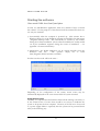
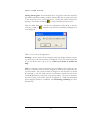
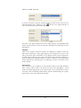
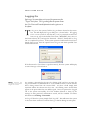
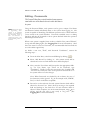
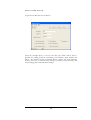
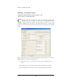
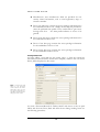
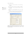
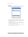
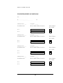
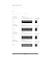
PX200 32 reader Access Control Administration Software Operator Guide 20-26 High Street | Greenhithe | KENT | DA9 9NN | United Kingdom | Tel +44 (0) 1322 370777 | Fax +44 (0) 1322 370076 | www.xplan.com PX200 ACCESS CONTROL ADMINISTRATION SOFTWARE Operator Guide Document Ref: Px200 User Manual V1(b) Access Control Services Limited 20-26 High Street, Greenhithe, Kent. DA9 9NN Phone 01322 370777 • Fax 01322 370076 www.xplan.com NOTE: The contents of this manual and the associated PLAN software applications are the property of Access Control Services Limited and are copyrighted. Any reproduction in whole, or part, is strictly prohibited. For more information on the terms of the software licence agreement please refer to the “ACS Software Licence.txt” file contained in the distribution disks or in the appendix of this manual. i Table of Contents System Specific Set-up and Configuration. _________________28 Introduction __________________2 Starting the software ___________3 Appendix 2 – Software Licence Agreement __________________29 Closing Down the system ________3 The Px200 Main Menu _________5 Basic Editing _________________7 Key Definitions ________________8 Drop-lists _____________________8 Tab-Pages_____________________9 Cursor Control ________________9 Logging On__________________10 Editing - Passwords ___________11 Editing - Card Records ________13 Creating Card Records_________14 Editing - Time Profiles_________16 Editing - Door Records ________18 History Analysis ______________21 Communications _____________22 Performing a Backup__________23 Existing Backup Strategy _________ 23 Manual backup _________________ 24 DOOR/READER SCHEDULE __25 Appendix 1 – Software Installation27 To Install Px200 Software_________27 Setting up your PC to run Px200 ___27 General PC Set-up and Configuration.27 i P X 2 0 0 U S E R G U I D E Introduction Introduction to conventions used throughout this manual. T he Px200 software application is an MS Windows based 32-bit software package designed for use with up to 16 PLAN200 2-reader local control units. Each PLAN200 control unit can control access for up to 1000 cardholders through either two separate doors, or a single door using IN and OUT reader configuration. For systems with a larger expansion requirements, we recommend the use of our PLAN640 software (used with either xPLAN200 or xPLAN400 controllers). Further support, sales information and the latest version of this manual can be viewed and downloaded from our product web-site at www.xplan.com. This manual assumes some knowledge of Computers and the Microsoft Windows operating system (especially the operation of the GUI). It is intended for guidance on the operation of Px200 Access Control Administration software only. For specific information that you may need about your Computer hardware or the Windows operating system itself, please refer to the documentation supplied. For speed and ease of understanding the Px200 software application will be referred to as the ‘System’, and the personnel who use the software will be referred to as ‘Operators’ or ‘Users’. The term ‘Cardholder’ will refer to a general card carrying member of staff. Note:-, Tips, Notes, or Definitions are occasionally printed in the left-hand margin (like this). These are there to provide additional information which is related to the subject which is being discussed in the main text. Sometimes the text will instruct the user to ‘press any key’ to select an option, or to change a value held in a selected field. In keeping with the conventions of the Windows user interface, this means any alpha-numeric key (including the Space bar) & not control keys such as Tab, Esc or Enter etc. Where an instruction includes a key name within angled brackets, this means that the operator must press the keys specified, however, if the system requires entry of a specific text string, this will be printed in upper-case within inverted commas, for example:… Type “MASTER” then Press <Tab> ….would indicate that the operator should type the keys M,A,S,T,E,R and then press the Tab key. Where the operator is required to use an on-screen button, the text will indicate this by requesting the user to ‘Click’ on the named button or icon. For example:… Click ‘OK’ to continue …. Would require the user to position the mouse over the button labeled “OK” and then ‘single click’ using the left hand mouse button. 2 P X 2 0 0 U S E R G U I D E Starting the software How to start the Px200 Access Control System Software As with any MS Windows Application, there are a number of ways to launch the software. For the purposes of this manual it will be assumed that there are two only two methods. 1) Automatically when the computer is powered up. This assumes that a Windows Short Cut to the Px200.exe program is included in the Start menu \Programs\Startup folder. This will usually be created by the installer during the software installation. (Note: Software installation is usually carried out by the installation engineers during the course of installation – see appendix 3 for more information). 2) Alternatively, the Px200 application can be started manually from the Windows task bar. The operator simply has to Click Start\Programs\PLAN and then on Px200. In either case the result will be the same… Depending on the configuration of the system, recent events may be automatically displayed on the event viewer when the system is started. Closing Down the system Generally, it is expected that the Px200 software will be running at all times, so in the normal course of events there would be no reason to shutdown the system or de-power the host computer. However, if the PC has to be moved or a power supply failure is expected, then the system can be powered down safely in the following way. 3 P X 2 0 0 U S E R G U I D E Closing the Program: If an authorised user is Logged On, then they must first quit whatever database editing or report function that they are using and return to the Main Menu Screen, (As shown above). Usually, this will be achieved by pressing <Alt><F4> or Clicking ‘ ’ in each of the editors that are open. From the Main Menu Screen use the key combination <Alt><F4> to exit the software, or click on ‘ ’. This will cause the Exit Confirmation Dialogue box to be displayed…. Click on ‘Yes’ to close the application. Warning: Never switch off the computer when the Px200 software is active e.g. when any of the menu screens are displayed. If the above procedure fails or you are unsure that is safe to do so;- contact your dealer or installer for help. Note: As with any system of this nature, the possibility for loss of data or even damage to hardware exists when the program is terminated unexpectedly due to power failure. The system software is designed so that the data loss should be restricted to only the small amount of information which was held in the volatile RAM memory at the time of the power failure. However to minimise the risk of losing even further, then the installation of a UPS (Un-interrupted Power Supply) should be considered. (See Performing a Backup for more information). 4 P X 2 0 0 U S E R G U I D E The Px200 Main Menu The Main Menu screen allows the user to see system activity as it occurs as well as providing access to the individual system editors. In most cases (depending on the configuration of the system) it will be noticed that when started, the software will automatically begin communicating with its network of PLAN200 field controllers. The data transactions between the Px200 PC and the local controllers will be displayed on the Event Viewer. When the system is left in this mode, events such as alarms, card violations and normal card transactions will be displayed as they occur. In addition to the display of communications information, the Main Menu screen also allows access to the individual system editors. Each Editor has a specific purpose (e.g. setting the clock, configuring user passwords, adding cards or reviewing history). However, since no user is logged on, all of the buttons are ‘Unavailable’ - except the Log On and Exit buttons. See Logging On for more information. When a user has logged on, depending on their password authority, the following buttons will be displayed, the function of each is described below… Edit Passwords: The Password Editor allows a suitably authorised system operator to control which users will be allowed to access the various other editors in the system. Edit Cardholders: Editing the Card Record Database allows the operator to Add, Delete, Edit or List card holder information. Edit Time Profiles: Time Profiles allow the operator to introduce the time of the day (and day of week) as a controlling factor over various functions within the system, the Time Profile Editor allows the operator to View, Edit List and Configure Time Profile Records. Edit Doors: The Door record Editor allows the user to View, Edit List and Configure the settings for each of the doors connected to the system. 5 P X 2 0 0 U S E R G U I D E Analyse History: The History Analysis feature allows the operator to view the card and alarm events stored on the system Communications: The Communications menu provides access to system configuration settings such as Manual or Automatic polling, PSTN settings (for remote site communications). Backup: The Backup menu allows the operator to make a backup copy of the data created using Px200 application. Alarm Ack: If the doors have been configured to report alarms, the alarm acknowledge button is used to silence and accept any alarms that are reported. Set Clock: The Set Clock function causes the software to synchronise the PLAN200 Controllers with the PC time. 6 P X 2 0 0 U S E R G U I D E Basic Editing A brief introduction to the some of the more commonly used controls within the Px200 system . W herever possible, the software has been designed to take advantage of a selection of ‘common database controls’. For example, moving between records within any of the database tables is achieved using the same mouse operation, in this case clicking either ‘ ’ or ‘ ’ to move up and down through the records. It will be seen that these controls take the form of Software ‘Buttons’ on the screen which are activated by a single click on the left-hand mouse button. A brief definition (along with the keyboard equivalent if available) for each Control Button is listed below: Close Editor: Will exit the current editor & return to the Menu bar (or the previous editor) <Alt><F4>. Print Report: This will display the relevant Print Dialogue Box, and allow the operator to print listings and reports. First Record: Will display the lowest record in the database file. <Ctrl><PgDn>. Prior Record: Will display the previous record. <PgDn> Next Record: Will display the next record. <PgUp> Last Record: Will display the highest record in the database file. <Ctrl><PgUp> 7 P X 2 0 0 U S E R G U I D E Edit Record: This will set the editor into ‘Insert/Edit’ mode and will allow changes to be carried out.. <F6> Save - Post Edit This key saves the data on the screen and will post it to the PLAN200 Local Control Units. <F2> If the key legend becomes ‘transparent’, this means that the function of the button is ‘unavailable’. This may be because of the password authority of the currently logged on operator or simply because of the current mode of the editor, e.g. The ‘Edit Record’ and ‘Save/Post Edit’ buttons are mutually exclusive. It can be seen in the list above that some Screen Buttons have keyboard equivalents. For some lesser used control functions there are keyboard only commands, these are listed below: Key Definitions <F2> Save: Pressing this key will save the data on the screen and send it to the PLAN200's. <F3> Save & Next: In addition to performing the same function as <F2> this key will select and display the next available record. <F4> Save & Quit: Will save the current data and send it to the PLAN200's. The system will then return to the Menu Bar or the previous editor. <F5> Browse Records: This will display a scrolling list box which will allow the operator to search for a record to display. Using this key in the cardholder record will allow the operator to search by a variety of sort criteria. <Ctl><S> Send-all: This option will flag all of the records in the current database and send them to the PLAN200 Local Control Units Drop-lists Throughout this manual the operator is asked to make selections from a range of options - in some cases these options are pre-defined, such as in Door record Editing where the Lock Mode is selected. In other cases the selection is from an operator defined list. In both cases the use of Windows Drop-down List Boxes are required. For speed the manual tends to refer to these as ‘Droplists’. Drop-lists make the selection of options extremely easy, and error free, they present the user with all of the available alternatives in an easily accessible form, without taking up too much space on the screen. The figure below shows a section from the Door Record editor… 8 P X 2 0 0 U S E R G U I D E It can be seen above, that the currently set time profile for the access level is ’Mon-Fri 09:00-17:00’. Clicking on the ‘ ’ button to the right hand side of the Free Profile field, will reveal the drop-list… To select a new Time Profile from the list, simply Scroll to the required Profile Name, and then Click to close the drop-list and update the field with the new information. Tab-Pages Many of the records within the database are displayed in windows which are split up into Tab-Pages. These pages appear to be arranged one on top of the other, and allow more information to be displayed than would otherwise be possible without filling up the screen and making the information difficult to read. Tab Pages are extremely simple to control… clicking on the required Tab Label, will cause the selected page to be displayed ‘on top’ so that data can be read or edited. Cursor Control All of the above are in addition to the standard controls of the MS Windows GUI, <Tab>,<Shift><Tab>, the cursor keys and <Alt><Backspace> are all used as and when appropriate to the task at hand. For an introduction to these and many other commands which will be useful in administrating the system, please refer to the on-line Windows help files. 9 P X 2 0 0 U S E R G U I D E Logging On Before any of the system editors can be accessed, the operator must first "Log-on" to the system.. The Log-on dialog allows the operator to enter their User Name and Password information in order to gain access to the software. T o Log-on to the system, Click the Log-on button located on the menubar, this will display the log-on dialog box - shown below. If Logging On to a new system for the first time, or if no password records have been set-up, type in the default User Name "MASTER", then, move to the Password entry box, and type the Password - “PLAN”, finally click on ‘Log On’ to complete the process. If the system password authorisation levels have already been set up, then the operator must Log-on with their specified User Name & Password. If the Password or User Name is typed incorrectly, then the system will display an error message as shown below. Note:- Passwords and User Names can be entered in upper or Lower case. To continue, acknowledge the error by clicking ‘OK’ and then re-enter the Log-in information as described above. Care should be taken to ensure that the data is being entered into the correct fields. To select a field simply click anywhere within the relevant text box area - the flashing cursor should then appear at the point where the text will be typed. Once an operator has Logged On to the system successfully, all of the facilities allowed to them, by the settings in their password authorisation record, will be available. For More information see Editing - Passwords. To Log off from the system, simply Click ‘Log Off’. This will return the system to the state where another User must first log on before editing can take place. 10 P X 2 0 0 U S E R G U I D E Editing - Passwords The Password Editor allows a suitably authorised system operator to control which users will be allowed to access the various other editors in the system. Note:- Because the degree of programming access granted to an individual operator is determined by the information stored in their User Record it is essential that access to the password Editing Screen is restricted. Using the Password Editor, each operator can be given a unique User Name and Password which will identify them to the system when logging on. The system is capable of identifying 256 different operators each of which will have a user record in the system database. Password controlled access to editing functions will then be restricted to those options defined within the operators individual password record. When a new system is supplied, there is always a default User, named "Master", set up with full editing rights, (See Logging On for more information). Since this is the same for every new customer, it is recommended that Passwords are set at the earliest opportunity. To define a new user, "Fred", with Password "Casablanca", execute the following steps… 1. From the Main Menu, select Password Editing by clicking ‘ 2. Select ‘Add Record’ by clicking ‘+’. The current record will be cleared and a new one with default values will be displayed. 3. Next, enter the User Name and Password in the appropriate fields. e.g. for User Name, type "Fred" & for Password, type "Casablanca". Finally, re-enter the password in the ‘Confirm’ field - this must be exactly the same as the password entered above or the system will not save the changes. ’. Note: When Passwords are checked by the software, the case of the characters used is ignored. E.g. in the example used, “FRED”, Fred, or “fred” would all be acceptable. 4. Proceed to set the authority for each system function which will be allowed to the new User. This is done by moving to the required field and clicking in the check box for each function which is allowed. When complete, save in the normal manner, using ‘ ’ (or <F2>), and the new user is now ready to "Log On". (See Logging On for more information). 11 P X 2 0 0 U S E R G U I D E A typical User Record is shown below:.. From the example above, it can be seen that user "Fred" will be able to perform any editing functions concerning Card Holders, Time Profiles and Doors. He will also be able to perform History analysis and create backups, however this user is restricted from editing or creating new passwords, and from changing the communications settings. 12 P X 2 0 0 U S E R G U I D E Editing - Card Records Editing the Card Record Database allows the operator to Add, Delete, Edit or List card holder information. C ards are added into the system by creating a individual record on the computer for each member of staff. This "Cardholder Record" contains information which will determine the freedom of access around the building for that person. The figure below shows a typical card record, it can be seen that the lower half of the record is split up into Tabbed Pages. Before card records can be created, the function and meaning of the various fields within the record must be understood… 1. Forename: Up to 32 characters of text can be entered into this field. 2. Surname: Up to 32 characters of text can be entered into this field. 3. Card Number: This field contains the Unique 8-digit card number. 13 P X 2 0 0 U S E R G U I D E 4. Miscellaneous: Two miscellaneous fields are provided for non security related information, such as Card registration, dept, or extension number. 5. Doors 1-8: This page contains the access privileges information for the cardholder for doors 1-8. Simply use the drop list provided to select the preferred time profile for the card holder to gain access through each door. No Time profile indicates no access to be granted. 6. Doors 9-16: This page contains the access privilege information for the cardholder for doors 9-16. 7. Doors 17-24: This page contains the access privilege information for the cardholder for doors 17-24. 8. Doors 25-32: This page contains the access privilege information for the cardholder for doors 25-32. Creating Card Records To begin adding a new card into the system, select ‘+’ from the control bar The current record should be cleared and a template, similar to the one shown below, will be displayed on the screen. Tip: to customise the field names in the Personnel record. Click on the current field name, then type the new name in the dialog box, click Done, and the new text will appear on the screen. To create a Personnel Record for "Sidney Smith" with Access to the car park 24Hrs and the main Front, Back and Stores doors during working hours use the following procedure;- 14 P X 2 0 0 Note: if your system is configured with an enrolment reader (usually situated adjacent to the PC) simply click read card instead of typing in the card number. . U S E R G U I D E 1. First name: "SIDNEY". 2. Surname: Enter the Last Name of the card holder, e.g. "SMITH". 3. Card Number: Key in the unique card number, in this case "25501239". 4. Next, enter any optional Miscellaneous data into the two Misc fields. 5. Finally, use the drop lists provided to select the desired time profile for each door at which access should be granted to this user.. Enter the First Name of the card holder, e.g. When the above data has been entered, the record should show… Check that the data displayed is correct and then press <F2> or Click on the ‘ ‘ Button to save the data. If the information shown is wrong, then, either move to the field which contains the mistake & correct it, or click ‘-‘ to clear all data fields & start again. 15 P X 2 0 0 U S E R G U I D E Editing - Time Profiles Time Profiles allow the operator to introduce the time of the day (and day of week) as a controlling factor over various functions within the system, the Time Profile Editor allows the operator to View, Edit List and Configure Time Profile Records. T ime Profiles, once set up, can perform a variety of tasks within the Access Control System, their main use is to define the times when a person is allowed access through their selected group of doors. This is done by preparing a number of different Time Profiles and then applying them to the relevant doors within the Card Record. The secondary application for time profiles is to use them to lock or unlock specific doors at pre-set times. This is achieved by associating a particular Time Profile to either a Bolt Profile or Free Profile in a given door record. For more information on the application & use of the Time Profiles once they have been created, see the relevant sections. E.g. Editing – Card Records, & Editing - Door Records. 16 P X 2 0 0 U S E R G U I D E It can be seen above that a Time Profile consists of a "Status Field", & 4 "Time Zones". For a Time Profile to operate, the Status must be set to ‘Active’ and at least one Time Zone must be set up. To change the Status of the record, Click on the check box next to the word Active, or move to the Status Check Box and use any key to toggle the status. Using the <Tab> key, will advance the cursor to the next editing field (<Shift><Tab> to go back to the previous field). A useful feature of Time Profile editing, is the option to disable a record, by setting the Status to "Off". Any member of staff with a Time Profile which has been set to ‘Off’ in this way, will not be allowed access at any door until such time as the record has been reinstated - set to Active. This facility will allow the operator to bar large groups of personnel with a single operation in the event of a security alert. Although it should be noted that any other function under the control of the disabled Time Profile (such as a Free or Bolt Profile) will also be suspended. Note:Start & End times must be entered in 24 Hour format (HH:MM). When defining a Time Profile the operator must complete at least one Zone e.g. Start Time, End Time & select a group of days. During the times specified in each Time Zone the Profile is said to be "Active". The Active period of the example record above would be 09:00 - 17:30 Monday to Friday. To set up the days on which each Time Zone will operate, simply place a tick in each of the check boxes for the desired days of the week. To add more Time Zones to the Time Profile (up to 4 per record), click on the appropriate Tab Page Label and repeat the above. Setting up Time Profiles for the first time… Instead of simply starting to add Time Profiles into the system, it is advisable to begin by surveying the opinions of others, as to what Time Profiles will eventually be needed. When a short list has been prepared it will be helpful to name each profile in a manner which will easily be recognised. The resulting list may look something like the following… a) b) c) d) e) 00:00 to 23:59 x 7 Days Mon. - Fri. 09:00 - 17:00 Mon. - Fri. 09:00 - 17:00 Sat. 09:00 - 13:00 Mon. - Fri. 06:30 - 23:59 Mon. - Thu. 06:30 - 18:00 Fri. 06:30 - 13:00 24 Hrs - 7 Days Office Hours Office Hours + Sat. a.m. Factory Hours Half Day Friday …. when all Profiles that may be required have been listed, select Time Profile Editing from the Menu Bar and create the records to match. 17 P X 2 0 0 U S E R G U I D E Editing - Door Records The Door record Editor allows the user to View, Edit, List and Configure the settings for each of the doors connected to the system. A mongst other things, door records are used to control the mode of operation for each door connected to the system. Some of this information is related to the particular type of locking device installed, and as such is essential to its correct operation. Door Records also control some optional features such as; Anti-Passback, Free/Bolt Profiles & Alarm settings. Generally, once set up, the Door Record Editor is not used on a day to day basis and may even be fully configured by the installer as part of the commissioning process. Shown below is a typical door record. When Door Record Editing is selected from the Main Menu the system will automatically display the first record. The door number relates to the position of the currently displayed door in the network, (See the Door Installation Schedule for a door number - door location cross reference). 18 P X 2 0 0 U S E R G U I D E The function & explanation of each of the control fields in the door record are listed below:1. Door Name: A 32 character door or location name can be keyed in here, to enable easy identification of each door during the creation of Card Records and listings etc. 2. Lock Release Time: The Release Time, or strike delay, is set in seconds and can be anything between 1 & 255. If the Lock Time is set to 0 then the system assumes that the strike delay will be 1 second. 3. Enrolment reader: This check box indicates that this reader is used for enrolment purposes using the card add procedure. 4. Alarm Delay Time: As with the Lock Time, the Alarm Delay Time is also in seconds and can be set for anything up to 255. However, if the Alarm Delay is set to 0, then alarms are disabled for that door. A door left open for longer than the Alarm Delay Time will cause a Door Left Ajar warning. Similarly, a door opened without a valid card entry (or exit request) will cause a Door Forced Alarm. For further information on what to do when an alarm occurs see Alarm Acknowledgment. 5. Free Profile: A Time Profile set here will cause the door to allow free access by permanently releasing the strike for the duration of the active period. At all other times the door will be accessible to valid card holders only. The example shows that a Time Profile ‘Mon-Fri 09:00 to 17:00’ has been selected. When no Profile is selected, the system will not set the lock to Free Access at any time. For further information see Editing - Time Profiles. 6. Bolt Profile: A Time Profile set here will cause the door to become permanently locked or "Bolted" whenever the selected Time Profile becomes Active. Bolted mode is so called because it has the same effect as a mechanical bolt applied to the door, e.g. no cards will be accepted at that door during the active period. In the example above no Bolt Profile is set. When no Profile is selected, the system will not Bolt the door at any time. For further information see Editing - Time Profiles. 7. Lock Mode: The operation of the lock output in the control panel, can be changed between ‘Safe’ (Fail Open) and ‘Secure’ (Fail Closed). In the sample record above, the door is fitted with a Fail Safe locking device (such as a mag-lock) and has been set to ‘Fail Open’. Consult your Supplier for more information on the types of lock that have been fitted. 19 P X 2 0 0 U S E R G U I D E 8. Passback/Interlock mode: Note:- For both INT and APB modes, each door in a configured pair must be connected to the same PLAN200 controller. The user can select a range of special operating modes for the doors in their system. By default, each door will be set-up to operate in standard mode whereby a valid card will cause the door to open for the pre-programmed delay. There are three special operating modes which function as follows:… APB: Otherwise known as Anti-Passback.. APB has two key benefits… a) Reporting is enhanced because cardholders are encouraged to use their cards for access, even when they arrive with other staff who might otherwise let them through the door (because they would not then be able to exit later on). b) Security is enhanced because cardholders can not simply pass their card back to a non cardholder to allow them to gain access. INT: Interlock mode is employed in high security applications, where a series of two doors (connected to the same PLAN200 controller) are used to gain access to the same controlled area. In a typical Interlock, there is a first “outer door” which is used to gain access to a dedicated lobby area, and a second “inner” door that is used to enter the secured area from the lobby. The Interlock mode is employed to ensure that only one door at any time is allowed to be open. INT/APB: This setting is used when it is desirable for a pair of readers to operate in both APB and Interlock modes. Interlock and APB modes are high security applications that require the installation to be configured in a specific way. Please consult your system provider before changing these settings. When configuring Door Records for the first time in a new system, or when adding doors to an existing system, the operator will require certain information from the installation company. E.g. a door chart will be needed to allocate the identifier name to each door. A list of door numbers and the relevant types of locking devices used will also be required to set up the Lock Mode. To assist both the system provider and the end user, a Door Schedule has been included with the system documentation which may be completed by the installer and left on site for future reference. 20 P X 2 0 0 U S E R G U I D E History Analysis The History Analysis feature allows the operator to view the card and alarm events stored on the system. E very time a card is used in the system, an entry is recorded in the history log. The date & time of every alarm or Manual override activation is also recorded. When this option is selected from the Main Menu, the most recent events will be displayed automatically. The scroll bar can be used to move up and down the list of operator actions. In many cases it will be desirable to filter the contents of the report before the listing is printed. The History analysis toolbar can be used to manipulate the list contents as follows… Show all events List by Card or Surname Specify a Date range for the list Specify a time window for the list Select which door locations are included Select event types to be included in the report Manage the archive by deleting events before a specific date Using the listing options above, a list can be created that includes only the information relevant to your query. When the on-screen list reflects your needs, click on the printer button to create a hard copy of your report. WARNING! With the exception of the archive management tool, all of the features within the history analysis are non-destructive to your data – so a degree of practice and experimentation is recommended. However, it should be noted that the “Prune” function (using the history deletion feature) will permanently remove data from the system. It is recognised that most systems will never create enough history data to require deletion within the life of the system, however, for the busiest sites, where managing the stored data is necessary, please use this facility with care. 21 P X 2 0 0 U S E R G U I D E Communications The communications menu is used to configure the operation of the system in relation to the PC communications with the PLAN200 control units.. T he PLAN system architecture has been designed so that the security function of the access control system is not dependant on PC operation or performance (e.g. access control decision making is carried out in real-time, by the locally intelligent PLAN200 field control panels). This architecture ensures that the system will carry on running even if the PC is switched off or has failed. For this reason, and to ensure that the PLAN200’s are configured with the correct information, it is necessary for the PC to communicate with the control units. The Px200 software supports fully automatic, real-time online comms between the PC and field equipment as well as a manually controlled ‘communicative when necessary’ option. When Auto Communications is selected, the Communicate menu is only used to switch the feature on for the first time. However, when manual communications is selected (e.g. in cases where the software is loaded onto a lap-top PC) the Communications menu is provided for the purpose of switching on Event polling and transmitting buffered data. To enable Auto Communications, select ‘Communications’ from the Main Menu, and then click on the ‘Communications’ drop down menu. Next, click on “Auto-Communicate”. Note: as shown above, tick will appear on the communications menu to indicate that Auto Communications is enabled. 22 P X 2 0 0 U S E R G U I D E Performing a Backup Creation of viable backups is essential. Any PC based system is exposed to the potential loss of data due to un-expected power failure , system hardware problems., software or operating system problems or even user mistakes. This section discusses the issues surrounding the creation of usable backup copies of your system data. T he PLAN system architecture has been designed so that the security function of the access control system is not dependant on PC operation or performance (e.g. day to day access decision making is carried out by the PLAN200 field control panels). Regardless of the fact that PC problems are un-likely to negatively impact card holders as they move around the building, it is still essential to create regular backups to protect your investment of time and effort in compiling the card holder database and the other files that are generated as a result of using the system (such as archived history files containing a record of the activities of staff as they move around the building). Existing Backup Strategy Most organisations have a backup regime in place, if this is the case, we generally recommend that the function of backing up the data created by the PLAN system is absorbed into the existing scheme. The following notes need to be observed by IT staff if they intend to use a network based automated backup agent to carry out this function… 1) All data created by the PLAN system is stored in the “c:\PLAN200” folder on the host PC. As long as the Px200 software is running (anywhere on the network) this data is ‘live’ and files may not be locked by the back-up software or the PLAN application could terminate with a data access error. If the proposed backup software is not able to allow the target files to be left open, then a manual PLAN backup must be performed (See note 2 below). Alternatively, the Px200 application must be shut-down before the backup can be performed. 2) The ‘built in’ manual backup utility will create a copy of the ‘live’ data in a folder called c:\PLAN200\backup. Data in this path can be copied at any time by third party backup applications. 3) Access to the archived data must be possible in whole or part, as in the event of a single table being corrupted or lost, it may not be desirable to restore all tables. 23 P X 2 0 0 U S E R G U I D E Manual backup The Px200 software is shipped with a built in backup utility which can be accessed from the main menu screen. The figure below shows the screen that will be displayed when the backup utility is accessed. It can be seen above that the c:\PLAN200\backup folder is pre-selected as the target destination for the backup procedure. A default backup can be performed simply by clicking on the “Backup” button at this point – with no other operator involvement. A default backup will create a copy of all of the Px200 working data in the selected destination folder. In the case of a default backup, these files will be located in the c:\PLAN200\backup folder. The option is provided for the user to alter the destination of the resulting files, by selecting a new folder or a different drive. 24 P X 2 0 0 U S E R G U I D E DOOR/READER SCHEDULE Date:- ............................................. By:- ................................................ .............................……………………................... Site:- Outstation No. ___ Loop No. ______ Local Door No. Door/Alarm Name/Location Door/Alarm No. on PC Door 1 Door 2 Outstation No. ___ Loop No. ______ Local Door No. Door/Alarm Name/Location Door/Alarm No. on PC Door 1 Door 2 Outstation No. ___ Loop No. ______ Local Door No. Door/Alarm Name/Location Door/Alarm No. on PC Door 1 Door 2 Outstation No. ___ Loop No. ______ Local Door No. Door/Alarm Name/Location Door/Alarm No. on PC Door 1 Door 2 25 P X 2 0 0 U S E R G U I D E Date:- ............................................. By:- ................................................ .............................……………………................... Site:- Outstation No. ___ Loop No. ______ Local Door No. Door/Alarm Name/Location Door/Alarm No. on PC Door 1 Door 2 Outstation No. ___ Loop No. ______ Local Door No. Door/Alarm Name/Location Door/Alarm No. on PC Door 1 Door 2 Outstation No. ___ Loop No. ______ Local Door No. Door/Alarm Name/Location Door/Alarm No. on PC Door 1 Door 2 Outstation No. ___ Loop No. ______ Local Door No. Door/Alarm Name/Location Door/Alarm No. on PC Door 1 Door 2 26 P X 2 0 0 U S E R G U I D E Appendix 1 – Software Installation Px200 software installation and the necessary PC configuration changes are outlined in this section. T he PLAN software will normally be installed and configured by the installation company. The guidance notes listed here, are provided for the purpose of assisting an on-site commissioning engineer (already familiar with the PC configuration and set-up requirements of the software). To Install Px200 Software 1) Close all applications. 2) Insert the Px200 installation disc into the CD drive. If the PLAN Setup wizard does not start automatically, click ‘Start’ then ‘Run’ on the Windows task bar and type “G:\Setup”, where ‘G:’ is the drive letter that represents your CD drive. 3) Click ‘Next’ to commence the software installation and follow the onscreen instructions. 4) When the software installation is completed proceed to ‘Setting up your PC” Setting up your PC to run Px200 There are two stages to setting up your PC to run the Px200 software application that has just been installed… General PC Set-up and Configuration. 1) Disable all power saving and remove any screen savers. 2) Set the screen resolution to 1024 x 764 pixels (XGA), High colour (or better) with Fonts set to ‘large’. 3) Configure the ‘regional settings’ for English UK, 24 Hrs clock, and ddmmyyyy date format. Note: It is possible that the regional settings could get changed by a future third party software application which may be installed at a later date. This could cause problems with the correct operation of some aspects of the PLAN software. Care should be taken in order to ensure that these settings are preserved. 4) Set up a suitable sound (wav file) for the windows ‘Exclamation’ event. This wav will be played in the event of a door alarm. 27 P X 2 0 0 U S E R G U I D E System Specific Set-up and Configuration. Only required if the software is not using Com Port 1 for panel communications. 1) Amend the c:\PLAN200\DPConfig.txt file as follows… Go to the section labeled [Com Port] and replace the standard com port setting ‘1’ with your preferred com port number. 28 P X 2 0 0 U S E R G U I D E Appendix 2 – Software Licence Agreement The contents of this manual and the associated PLAN software applications are the property of Access Control Services Limited and are copyrighted. Use of the software is governed by the terms of the ACS Software Licence Agreement... acceptance of which forms part of the software installation. The SLA is reproduced here for reference purposes. Access Control Services Software Licence Agreement This software is protected by both United Kingdom copyright law and international treaty provisions. You must treat this software just like a book, except that you may copy it onto a computer to be used and you may make a single archival copy of the software for the sole purpose of backing up our software and protecting your investment from loss. "Just like a book", means, for example, that this software may be used by any number of people, and may be freely moved from one computer to another, so long as there is no possibility of it being used at one location or on one computer while it is being used at another. Just like a book can not be read by two different people, in two different places, at the same time, neither can the software be used by two different people in two different places at the same time (unless, of course, the copyright is being infringed). Terms and Conditions 1) DEFINITIONS. The following expressions shall have the following meanings: "ACS" - Access Control Services Limited, whose registered office is at 20-26 High Street, Greenhithe, KENT, DA9 9NN. UK. "Licensee" or "End user" - person, firm or company that makes use of the installed the software. "Proprietary Information" - all intellectual property rights including but not limited thereto all copyrights, design rights (registered and unregistered), patents, trademarks, designs, formula, code and other similar data relating to the Software. "Software" - each software program provided by ACS, including any documentation, modifications, improvements or updates directly or indirectly supplied to the Licensee. 2) LICENCE. The software is licensed, not sold. You own the media on which the software is provided to you but nothing more except as provided herein. Subject to the terms and conditions of this agreement, ACS grants you (the licensee) the limited right to use one (1) copy of the specified version of the software on any single computer. In the event of PC failure, or hardware upgrade, you may transfer the software from one computer to another as long as it is not used on more than one computer at a time. You may not transmit the Software from one computer to another in a network or to serve multiple users. In multi-user applications a new licence must be acquired for each instance of the software (e.g. an additional licence for each PC on which the software is installed). 3) BACKUP. Solely for your own backup purposes, you may make one (1) copy of the software in the same form as it is provided to you. You may not copy any of the printed material (if any) for any reason. You have no ownership or proprietary rights in or to the Software. You agree that the Software will not be used, in any manner, in violation of any applicable law. 4) COPYRIGHT. The Software is owned and copyrighted by ACS and is protected by United Kingdom copyright laws, other applicable copyright laws and international treaties. ACS reserves all rights regarding the Software. ACS authorise usage of the Software only in accordance with the terms and conditions stated in this agreement. You may not remove any copyright or proprietary notices from the Software. 5) GENERAL USAGE. Neither you, anyone at your direction, nor any third party, shall take the following actions with regard to the Software, or any portion thereof to modify, change, decompile, recompile, disassemble, reverse engineer, adapt, create derivative works, translate or reproduce the software. In any event, you will notify ACS of any information derived from reverse engineering or such activities and the results thereof will constitute confidential information owned by ACS which may be used only in connection with the software. 29 P X 2 0 0 U S E R G U I D E 6) COMMERCIAL USAGE OF PROPRIETARY INFORMATION. Under no circumstances shall you, the end-user, be permitted, allowed or authorised to commercially exploit the intellectual property belonging to ACS contained within the software, or any portion thereof. Neither you, nor anyone at your direction nor any third party shall take the following actions with regard to the software, or any portion thereof; to sell, rent, lend, lease, commercially exploit or use the software for any commercial purpose. 7) DISTRIBUTION. Any distribution is prohibited. Under no circumstances shall you, the end-user, be permitted, allowed or authorised to distribute the software, or any portion thereof. 8) UPDATES. ACS reserves the right to update the contents of the software and its associated files, documentation and/or other elements, at its discretion from time to time, without the consent of or any obligation to, any licensed users or distributors. 9) LIMITED WARRANTY. i) ACS warrants that, if properly installed, and operated on a computer for which it was designed the software will perform substantially in accordance with the accompanying documentation for a period of one (1) year from the date of purchase of the software. ii) Due to the inherently complex nature of computer software, ACS does not warrant that the software or the documentation is error free, will operate without interruptions, be compatible with all equipment and software configurations, or will otherwise meet your needs. You are advised to verify the function of the software and make regular backup copies. iii) ACCORDINGLY, THE SOFTWARE IS PROVIDED "AS-IS". NO WARRANTIES OF ANY KIND, EXPRESS OR IMPLIED, WARRANTIES OF THE MERCHANTABILITY OR FITNESS FOR ANY PURPOSE WITH RESPECT TO THE SOFTWARE ARE MADE AS TO IT OR ANY MEDIUM IT MAY BE ON. iv) Your sole remedy and Access Control Services entire liability will be at our discretion, either repair or replacement of the software, or return of the price paid for the software. 10) REMEDIES. ACS WILL NOT BE LIABLE AND WILL PROVIDE NO REMEDY FOR LOST DATA, LOST SAVINGS, LOST PROFITS, SPECIAL, INCIDENTAL, CONSEQUENTIAL, PUNITIVE, INDIRECT OR ANY OTHER DAMAGES ARISING FROM NEGLIGENCE, STRICT LIABILITY, BREACH OF WARRANTY, BREACH OF CONTRACT, EVEN AFTER NOTICE OF THE POSSIBILITY OF SUCH DAMAGES OR FOR ANY CLAIM BY ANY OTHER PARTY. YOU AGREE THAT THE ENTIRE LIABILITY OF ACS AND YOUR EXCLUSIVE REMEDY SHOULD THE ABOVE LIMITATION BE HELD TO BE VOID, INVALID OR ILLEGAL BY A COURT, SHALL BE THE RETURN OF THE PURCHASE PRICE PAID OR REPLACEMENT OF THE SOFTWARE. 11) TRANSFER. Neither this agreement nor any part or portion of it shall be assigned or sublicensed, except as described herein. 12) ASSIGNMENT. ACS reserves the right to assign the benefit and protection offered by this agreement to another party or organisation without notice or obligation to any existing users. 13) SURVIVAL. Should any provision of this agreement be held to be void, invalid, unenforceable or illegal by a court, the validity and enforceability of the other provisions shall not be affected thereby. If any provision is determined to be unenforceable, you agree to a modification of such provision to provide for enforcement of the provision's intent, to the extent permitted by applicable law. Failure of a party to enforce any provision of this agreement shall not constitute or be construed as a waiver of such provision or the right to enforce the provision. The following provisions shall survive the termination of this agreement: paragraphs 4., 5., 6. and 7. 14) ENTIRE AGREEMENT. This agreement constitutes the entire agreement between you, the end-user, and ACS and supersedes any prior written or oral agreement concerning the software. ACS is not bound by any action, statements, or any provisions made by anyone else. No modification or change in this agreement shall be valid or binding upon ACS unless in writing. 15) APPLICABLE LAW. This agreement shall be governed by the laws of the United Kingdom. You agree to jurisdiction and venue in the courts located in London, U.K. for all claims, disputes and litigation arising under or related to this agreement. The export of this product is governed by U.K. export regulations. BY USING THE SOFTWARE YOU ACKNOWLEDGE THAT YOU HAVE READ AND UNDERSTOOD THIS AGREEMENT AND YOU AGREE TO BE BOUND BY THIS AGREEMENT'S TERMS AND CONDITIONS. YOU ALSO AGREE THAT THIS AGREEMENT IS THE COMPLETE AND EXCLUSIVE STATEMENT OF THE RIGHTS AND LIABILITIES OF THE PARTIES AND SUPERSEDES ALL 30 P X 2 0 0 U S E R G U I D E PROPOSALS OR PRIOR AGREEMENTS, ORAL OR WRITTEN AND ANY OTHER COMMUNICATION BETWEEN THE PARTIES RELATING TO THE SUBJECT MATTER OF THIS AGREEMENT. 31