1
On Chip Debug Support
C166S
OCDS Module
1)
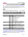
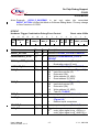
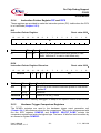
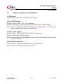
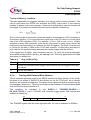
The first option (OR) is intended to be used for the case mux_r == mux_e only and in particular to have four
IP triggers. In case of different comparison sources this option results in a complex behavior, because the
triggers of for instance IP and W_ADR are created in different pipeline stages of the CPU.
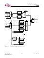
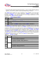
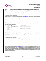
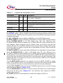
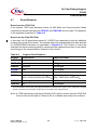
The COM_R field enables the range comparison to be included in the ocds_trgevt
generation (Figure 2-2). For in-range comparisons, DCMPG is used as the upper
boundary and DCMPL is the lower boundary. For out-of-range comparisons, it is the
other way round. Table 2-6 lists the options:.
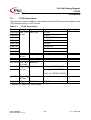
Table 2-6
COM_R Field of DTREVT
Value trg_r signal
00
0 (not enabled)
01
In range: 1 if DCMPG > input > DCMPL, otherwise 0
10
Reserved
11
Out of range: 1 if (DCMPG > input) or (input > DCMPL), otherwise 0
The MASK_E bit distinguishes between masked or unmasked input for the equal
comparison (Figure 2-2). In the masked case, DCMP0 controls the relevant bits for the
comparison. All bits of the input signal where the associated DCMP0 bit is 0 are also set
to 0 prior to the comparison. Note that the comparison values in DCMP1 and DCMP2
must also be 0 where the DCMP0 mask is 0. Otherwise, the comparison will not match.
The SELECT_E field enables the equal comparisons to be included in the ocds_trgevt
generation and selects which is used (Figure 2-2). Note that for masked comparisons,
the SELECT_E field must be set to 10B or 11B. Table 2-7 lists the options:.
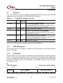
Table 2-7
SELECT_E Field
Value mask_e trg_e signal
00
0
0 (not enabled)
01
1 if DCMP0 matches, otherwise 0
10
1 if DCMP0 or DCMP1 match, otherwise 0
11
1 if DCMP0 or DCMP1 or DCMP2 match, otherwise 0
00
1
0 (not enabled)
01
0 (always)
10
1 if DCMP1 matches, otherwise 0
11
1 if DCMP1 or DCMP2 match, otherwise 0
User’s Manual
OCDS C166S, V 1.0
-18-
V 1.1, 2001-08