1
RelComm, Inc.
September 2010
i-COS User’s Manual
integrated Code Operated Switch
i-COS Configurations
4, 8, 12 & 16 Ports
RS - 232
RS - 422
Page 1 of 27
Rev L. 09/10
WARNINGS
When you are working within the unit, be certain that the power is
disconnected. High voltages that can cause electrical shock are
present on the power supply when power is applied.
This equipment generates, uses and can radiate radio frequency
energy and, if not installed and used in accordance with this
Instruction Manual, may cause interference to radio communications,
It has been tested and found to comply with the limits for a Class A
computing device pursuant to Subpart J of Part 15 of FCC Rules,
which are designed to provide reasonable protection against such
interference when operated in a commercial environment. Operation
of this equipment in a residential area is likely to cause interference,
in which case the user, at user’s expense, will be required to take
whatever measures may be required to correct the interference.
Page 2 of 27
Rev L. 09/10
Table of Contents
Table of Contents
3
SECTION 1 – INTRODUCTION.....................................................................4
1.1 GENERAL
1.2 OPERATIONAL DESCRIPTION
1.2 SPECIFICATIONS
4
4
6
SECTION 2 – INSTALLATION......................................................................8
2.1 GENERAL
8
2.1.1 INSTALLATION of the RACK-MOUNTABLE UNIT
8
2.2 SWITCH SETTINGS
9
2.2.1 RS232 PORT CONFIGURATION SWITCHES
9
2.2.2 AUTO-TIMEOUT, SWITCH TIME & RS 232/422
13
2.2.3 HANDSHAKE CONTROL, PORT DECODER & POWER-ON RESET ......13
2.2.4 DATA FORMAT
14
2.2.5 POWER-ON PORT SELECTION & GRAPHICS MODE
14
2.2.6 ARMING CODE SETTINGS
15
SECTION 3 – OPERATION...........................................................................19
3.1 POWERING THE UNIT
3.1.1 FRONT PANEL INDICATORS
3.2 ARMING CHARACTER & PORT SELECT CHARACTER
3.3 COMMUNICATION ERROR CONDITIONS
3.4 AUTO TIME OUT
3.5 RESET BUTTON
3.6 LOCK-OUT
3.7 MODES OF OPERATION
3.7.1 TEXT MODE
3.7.2 TRANSPARENT MODE
3.7.3 GRAPHICS MODE
3.8 TROUBLESHOOTING
3.9 i-COS 4/8/12/16 PORT INFORMATION
3.10 BASIC TEST PROGRAM FOR THE i-COS
NOTES 24
19
19
19
20
21
21
21
21
21
21
22
22
23
24
NOTES...........................................................................................................25
EIA-CITT MODEM TABLE (DCE) – TERMINAL (DTE) – INTERFACE.....26
LIMITED WARRANTY
27
Page 3 of 27
Rev L. 09/10
SECTION 1 – INTRODUCTION
1.1
GENERAL
The integrated Code Operated Switch (i-COS) is an asynchronous RS232C and/or
RS422 switch, available in configurations of 4, 8, 12 and 16 subordinate-ports with
one master port. For information or to order multiple-port devices, please contact
your sales source, or see our contact information on page 25 in this manual.
The i-COS can be configured RS232 on all Ports, RS422 on all Ports, or a
combination (Master RS232 and all Subordinate Ports RS422, or Master RS422 and
all Subordinate Ports RS232). i-COS/4 may be configured as RS422 in the field;
i-COS/8, /12 and /16 must be configured RS422 at the factory, requested at the
time an order is placed or return retro-fit. It is recommended that the user examine
the original purchasing documents to verify the configuration of the unit as received.
Additionally, the i-COS may be configured with an optional internal modem (RS232
only), available at time of order or as a factory upgrade.
1.1.1
DEFINITIONS (definitions for industry standard RS 232/422 are not
included)
FE: Framing Error
TRE: Transmit Register Empty
M or M-Port: Master Port
ST: Switch Time
LSB or lsb: Least Significant Bit
1.2
PE: Parity Error
CIN: Control In
S or S-Port: Subordinate/Slave Port
CD: Carrier Detect
MSB or msb: Most Significant Bit
OPERATIONAL DESCRIPTION
Under code control, the Master Port can select any of the Subordinate Ports by
transmitting the proper control and switch address code. The Master device
(CPU/Terminal) selects any of the other Ports (Printers/modems/terminals) by
transmitting the proper arming and switching code. A communications link to the
Master Port can also be made by any of the subordinate devices by transmitting its
own port address code while the switch is in the Switch Time. Once the
communications link is established, all other Ports are locked out. The Ports remain
locked out until either the Master Port or the selected Subordinate Port transmits an
arming character. Reception of the arming character causes the i-COS to break all
switched connections between the Master and Subordinate Ports and places the unit
back into Switch Time.
The typical TEXT mode transmission pattern is:
<ARMING CODE, PORT ADDRESS CODE, DATA......>
Page 4 of 27
Rev K 01/09
All Ports have female DB25S connectors. Configuration switches on all ports allow
configuration to a Data Terminal Equipment (DTE) or Data Computer Equipment
(DCE). The device also allows configuration of many user-selectable features,
including: word length, baud rate, stop bits, DCE/DTE, control handshake, graphics,
arming character, transparent mode, inactivity timeout, default power-up and lockout.
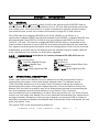
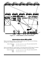
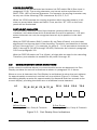
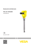
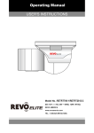
Figure 1-1 shows a typical network involving various peripherals. The computer
selects which device it wishes to communicate with by transmitting the proper arming
and port switching code. If desired, the connection can be made from a terminal (if
these devices know the proper codes).
The i-COS will also work in applications where the arming character can appear in the
data stream (such as graphics, and error checking). When in graphics mode, a
switch-selectable idle time after the data stream is required before the arming
character is valid. If an arming character is in the data stream, it will pass without
causing the i-COS to switch.
X.25
Code Operated
Switch
Computer
Sub-Ports
Modem
Data
Master
Multiplexer
Printer
Data Port
Figure 1-1. Typical Application
Page 5 of 27
Rev L. 09/10
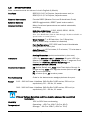
1.2
SPECIFICATIONS
Note: measurements are shown in both English & (Metric)
Interface:
RS232/V.24, Full Duplex, Asynchronous and/or
RS422/V.11, Full Duplex, Asynchronous
External Connectors:
Female DB25 (Master Port and Subordinate Ports)
External Controls:
MODE toggle switch; RESET push button switch
Internal Controls:
Many functional parameters are switch selectable,
including:
High Baud (Bd) Rate: 1200, 4800, 9600, 19.2K,
38.4K, 57.6K, 76.8K, 115.2K
Note: Low Baud Rate (300 & 2400 through 76,800) available on
special order or contact factory.
Word Format (7 or 8 Data bits; 1 or 2 Stop bits;
Odd or Even Parity, enabled or disabled)
Port Configuration: DTE/DCE and Control Handshake
configurable for each port
Auto Timeout: (0.5 minutes, 1.5 minutes, 7.3 minutes or
disabled/infinite)
Arming Character: (switch selectable by the user)
Indicators:
LED’s for SWITCH TIME & LOCK-OUT; Bi-color LED’s for
Master Port DATA and CONTROL status; 7-segment Port
Display for PORT SELECTED, WatchDog and
COMMUNICATION ERRORS
Internal Connectors:
AS (Active Serial) and JTAG (Joint Test Action Group) for
programming; AEX: ASIC signals access (future use); J6 –
J8: 4-port expanders;
P1: modem port; J9: modem power
Port Addressing:
Code in the data stream assigns/selects the port.
Power:
100 - 130 VAC fuse: Littelfuse 3AG Slo-Blo 313P series, 500 mA (or
equivalent), 50 – 60 Hz, 11 watts.
200 - 240 VAC fuse: Littelfuse 3AG Slo-Blo 313P series, 250 mA (or
equivalent), 50 – 60 Hz, 11 watts.
WARNING
Primary Voltage Selection and Fuse may be changed by a qualified
technician.
Humidity:
15% to 95% Non-condensing
Temperature:
Operating: +32oF to 104oF (0oC to 40oC)
Storage: - 40oF to 158oF (-40oC to 70oC)
Page 6 of 27
Rev L. 09/10
Enclosure:
a) Aluminum, NEMA Standard 19 inch rack mount
b) Plastic, standalone (i-COS/4 or /8 only)
1.2
SPECIFICATIONS (continued)
Size:
Rack mount:
•
i-COS/4 or /8: 19” W x 10.75” D x 3.5” H; (48.26 cm W x
27.31 cm D x 8.89 cm H); 2-RETMA vertical rack space
•
i-COS/12 or /16: 19” W ) x 10.75” D x 5.25” H; (48.26 cm W
x 27.31 cm D x 13.34 cm H); 3-RETMA vertical rack space
Standalone:
•
12.25” W x 11.75” D x 2.5” H; (31.115 cm W x 29.845 cm D
x 6.35 cm H)
Weight:
Rack mount: 5.5 pounds (2.5 kg)
Standalone: 4.0 pounds (1.8 kg)
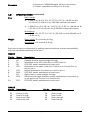
Each port is highly configurable by setting internal switches, to allow compatibility
with the equipment attached to the port.
RS232
Pin No. Name
Description
1
2
3
4
FG
TD
RD
RTS
5
6
7
8
CTS
DSR
SG
DCD
20
DTR
Chassis Ground, wired straight through
Selectable to be DTE (Data Out) or DCE (Data In)
DTE/DCE switch selectable for each port
Selectable to be open, pulled up, Control In or Control Out, or
tied to pin 5
Switch selected to be pulled up or tied to pin 4
DTE/DCE switch selectable for each port
Signal return, wired straight through
Received line signal detector; switch selectable to be pulled up
or not pulled up, Control In or Control Out
DTE/DCE switch selectable for each port
RS422
Pin No. Description
12
13
14
15
Control in low
Control in high
Control out high
Control out low
Pin No.
18
19
24
25
Page 7 of 27
Description
Data in high
Data in low
Data out high
Data out low
Rev L. 09/10
SECTION 2 – INSTALLATION
2.1
GENERAL
Installation of the i-COS is a matter of connecting the Master and Subordinate ports
to the proper communications equipment using the
DB25 (female) connectors.
For RS232 operation, internal DIP port configuration switches allow the user to
individually configure each port for either DTE or DCE operation, as necessary. For
RS422, operation is independent of the port switch settings. Note: Only the Master
Port and S-Ports 0 – 3 are configurable in the field as RS422; S-Ports 4 – 15 must
be configured RS422 at the factory.
When viewing the i-COS from the rear panel:
•
i-COS/4 – the left most connector is the Master Port; the Subordinate Ports
connectors are numbered from left to right 0, 1, 2 and 3
•
i-COS/8 – additional Subordinate Ports connectors left to right 4, 5, 6 and 7
•
i-COS/12 – additional Subordinate Ports connectors left to right 8, 9, 10
and 11
•
i-COS/16 – additional Subordinate Ports connectors left to right 12, 13, 14
and 15
Reference the enclosed Addendum “Factory Presets” to note the unit’s internal
switch settings preset at the factory. Determine if any internal switches must be
reconfigured to match your particular application.
2.1.1
INSTALLATION of the RACK-MOUNTABLE UNIT
The rack-mount unit is designed to fit a NEMA Standard 19 inch rack. Install this unit
using all four mounting holes. The cover helps stiffen the entire unit, therefore before
installation, insure all cover screws are tight.
After installation, dress cables in such a manner that they do not apply excessive
strain on the cable connectors.
Page 8 of 27
Rev L. 09/10
2.2
SWITCH SETTINGS
WARNING
IF ANY INTERNAL DIP SWITCH SETTINGS MUST BE CHANGED, BE
CERTAIN THAT THE POWER IS DISCONNECTED FROM THE UNIT BEFORE
REMOVING THE COVER.
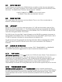
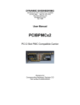
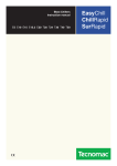
Refer to Figure 2-1 for the location of the switches. In the following switch
descriptions, a closed switch may be shown as “CLOSED”, “C” or “CL”, and an open
switch may be shown as “OPEN”, “O” or “OP”.
2.2.1
RS232 PORT CONFIGURATION SWITCHES
(SWA1 through SWA5; and SWB1 through SWB5)
Every port has a pair of eight-position DIP configuration switches (switch A and switch
B) to select which pins are set to provide the required combination of inputs, outputs
and control handshaking for RS232 (not required for RS422).
A DTE (Data Terminal Equipment) device transmits data on pin 2 and receives data in
on pin 3. The control output pins are pin 4 (RTS) and pin 20 (DTR). The control input
pins are pin 5 (CTS), pin 6 (DSR) and pin 8 (DCD). Terminals, personal computers,
DEC computers are examples of DTE devices.
A DCE (Data Communication Equipment) device is the converse of DTE, that is, a DCE
transmits data on pin 3 and receives data in on pin 2. The control output pins are pin
5 (CTS), pin 6 (DSR) and pin 8 (DCD). Modems, HP computers and DG computers are
examples of DCE devices.
When connecting two devices together with a straight pinned serial cable, the devices
must be converse types (one DTE and one DCE). Thus, the i-COS ports must be
configured to be the converse type of the connecting device(s).
For the i-COS/4, switches SWA1/SWB1 are for the Master Port. Switches
SWA2/SWB2 through SWA5/SWB5 are for Subordinate Ports 0-3 respectively. (If
expansion boards are installed, the ports are controlled by the switches located
directly behind each port.) See Figure 2-1, page 10.
In the following description, SWA is the left 8-position DIP switch and SWB is the right
eight-position DIP switch as you look at the i-COS with the front panel facing you. See
Figure 2-1, page 10.
Page 9 of 27
Rev L. 09/10
Figure 2-1. COMPONENT LAYOUT DIAGRAM
Quick Set Up for switches SWA and SWB
When connecting a modem or a host computer port (HP, DG), use the following
settings and a straight pinned serial cable:
Switch Positions
SWA
SWB
1 2 3 4 5 6 7 8 (The port looks like DTE)
0 0 0 0 C 0 0 C
0 C C 0 C C C C
When connecting a PC, serial printer, or a dumb terminal (VT100, Wyse, Computer,
etc.), use the following switch settings and a straight pinned serial cable:
Switch Positions
SWA
SWB
1 2 3 4 5 6 7 8 (The port looks like DCE)
0 0 0 0 0 C C 0
C 0 0 C C C C C
Page 10 of 27
Rev L. 09/10
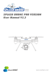
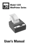
To configure a port’s data and control leads, reference Tables 1 through 3 below. In
general (not required for RS422):
•
DCE or DTE data leads are selected via SWA positions 5 through 8
•
Control handshaking is selected via SWA and SWB, positions 1 through 4.
The i-COS can pass one hardware control lead in both directions (M-Port to S-Port, SPort to M-Port).
Legend: C = Closed O = Open
Table 1 – DTE CONFIGURATION
POSITIONS
FUNCTIONS
DSR/DTR as
Cin/Cout
RTS/DCD as
Cout/Cin
SWA
SWB
1
2
3
4
5
6
7
8
1
2
3
4
O
O
O
O
C
O
O
C
O
C
C O
See Table 3
C
O
O C
C
O
O
C
O
O
O
See Table 3
O
5
6
7 8
Table 2 – DCE CONFIGURATION
POSITIONS
FUNCTIONS
DSR/DTR as
Cout/Cin
RTS/DCD as
Cin/Cout
SWA
SWB
1
2
3
4
5
6
7
8
1
2
3
O
O O
O
O
C C O
C
O
O C
See Table 3
O
C C O
O
C
O
O
O
See Table 3
C O
4
O
5
6
7 8
Additionally, Switch B, positions 5 through 8, are used to tie RTS to CTS, or pull RTS,
CTS or DCD high:
Table 3 – DCE CONFIGURATION
POSITIONS
SWA
SWB
5
FUNCTIONS
Default
Tie RTS toCTS
RTS & CTS
pulled high
RTS pulled high
CTS pulled high
DCD pulled high
6
7 8
O O O O
O C C O
O C C C
O C O C
O O C C
C O O O
Page 11 of 27
Rev L. 09/10
Figure 2-2. Port Configuration
Page 12 of 27
Rev L. 09/10
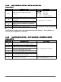
2.2.2 AUTO-TIMEOUT, SWITCH TIME & RS 232/422
Switch SW-T
POSITION
1&2
3
4
5
6
7
8
DESCRIPTION
Auto Time Out (after data transmission)
S-Port Allow Switch Time
Allows S-Port to select a connection
to M-Port
M-Port Allow Switch Time
Allows M-Port to select a connection
to S-Port
M-Port RS232/RS422 select
S-Ports RS232/RS422 select
SETTINGS
1
2_
CL CL
OP CL
CL OP
OP OP
0.5 min
1.5 min
7.3 min
Infinite/Disable
CL = Enable; OP = Disable
CL = 232, OP = 422 (see NOTE)
NOTE: RS422 configurable in the field for M-Port and S-Ports 0 – 3 only; S-Ports 4 –
15 must be configured at the factory.
2.2.3
HANDSHAKE CONTROL, PORT DECODER & POWER-ON RESET
Switch SW-C
POSITION
1
2
3
4
5
6
7
8
DESCRIPTION
BREAK transmission for a received
Framing Error or receive Parity Error
S-Port handshake use TRE for /CIN_M
M-Port handshake use TRE for /CIN_S
Reset to Switch Time. Caused by a
drop of Subordinate Port CIN_S
Control Line Out while in ST
Port Decoder in ST
Reset to Switch Time. Caused by a
drop of Master Port CIN_M
SETTINGS
CL = Disable; OP = Enable
CL = Limits to ports 0 - 7
OP = Enables ports 0 - 15
Extended port decode
Page 13 of 27
Rev L. 09/10
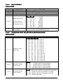
2.2.4 DATA FORMAT
Switch SW-F
POSITION
1
2
3
4
DESCRIPTION
Word Length
Stop Bits
Parity
Parity Enable
High Baud Rate
5, 6 & 7
8
(Factory default –
See p. 6 for Low
Baud Rate option)
Transceiver
Loop Back
SETTINGS
CL=8 bits, OP=7 bits
CL=1 stop, OP=2 stop
CL= Odd Parity; OP= Even Parity
CL= Disabled; OP= Enabled
5
6 7_
CL CL CL =
1200
OP CL CL =
4800
CL OP CL =
9600
OP OP CL = 19,200
CL CL OP = 38,400
OP CL OP =
57,600
CL OP OP = 76,800
OP OP OP = 115,200
CL = No Loop Back;
OP=Loop Back (troubleshooting only)
2.2.5 POWER-ON PORT SELECTION & GRAPHICS MODE
Switch SW-P
POSITION
DESCRIPTION
1–4
Power-on Port
Selection
5&6
Graphics Mode
Gap Timing
7&8
Graphics Mode
Timer Reset
SETTINGS
1 2
3 4_
CL CL CL CL = Port 0
OP CL CL CL = Port 1
CL OP CL CL = Port 2
OP OP CL CL = Port 3
CL CL OP CL = Port 4
OP CL OP CL = Port 5
CL OP OP CL = Port 6
OP OP OP CL = Port 7
CL CL CL OP = Port 8
OP CL CL OP = Port 9
CL OP CL OP = Port 10
OP OP CL OP = Port 11
CL CL OP OP = Port 12
OP CL OP OP = Port 13
CL OP OP OP = Port 14
OP OP OP OP = Port 15
5 6_
CL CL =
5 Word Gap in transmission
OP CL = 25 Word Gap in transmission
CL OP = 50 Word Gap in transmission
OP OP = 100 Word Gap in transmission
7 8_
CL CL = M-Port S-Port character Bi-direction
OP CL = M-Port S-Port character received
CL OP = M-Port S-Port character received
OP OP = Reset Disabled
Page 14 of 27
Rev L. 09/10
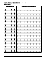
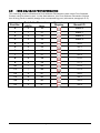
2.2.6 ARMING CODE SETTINGS
Switch SW-A
ARMING CHARACTERS
ASCII
CTRL
HEX
DECIMAL
ARMING CHARACTER SWITCH POSITIONS
LSB
1
2
3
4
5
6
7
MSB
8
NUL
@
ØØ
Ø
C
C
C
C
C
C
C
C
SOH
A
Ø1
1
O
C
C
C
C
C
C
C
STX
B
Ø2
2
C
O
C
C
C
C
C
C
ETX
C
Ø3
3
O
O
C
C
C
C
C
C
EOT
D
Ø4
4
C
C
O
C
C
C
C
C
ENQ
E
Ø5
5
O
C
O
C
C
C
C
C
ACK
F
Ø6
6
C
O
O
C
C
C
C
C
BEL
G
Ø7
7
O
O
O
C
C
C
C
C
BS
H
Ø8
8
C
C
C
O
C
C
C
C
HT
I
Ø9
9
O
C
C
O
C
C
C
C
LF
J
ØA
1Ø
C
O
C
O
C
C
C
C
VT
K
ØB
11
O
O
C
O
C
C
C
C
FF
L
ØC
12
C
C
O
O
C
C
C
C
CR
M
ØD
13
O
C
O
O
C
C
C
C
SO
N
ØE
14
C
O
O
O
C
C
C
C
SI
O
ØF
15
O
O
O
O
C
C
C
C
DLE
P
1Ø
16
C
C
C
C
O
C
C
C
DC1
Q
11
17
O
C
C
C
O
C
C
C
DC2
R
12
18
C
O
C
C
O
C
C
C
DC3
S
13
19
O
O
C
C
O
C
C
C
DC4
T
14
2Ø
C
C
O
C
O
C
C
C
NAK
U
15
21
O
C
O
C
O
C
C
C
SYN
V
16
22
C
O
O
C
O
C
C
C
ETB
W
17
23
O
O
O
C
O
C
C
C
CAN
X
18
24
C
C
C
O
O
C
C
C
EM
Y
19
25
O
C
C
O
O
C
C
C
SUB
Z
1A
26
C
O
C
O
O
C
C
C
ESC
[
1B
27
O
O
C
O
O
C
C
C
FS
\
1C
28
C
C
O
O
O
C
C
C
GS
]
1D
29
O
C
O
O
O
C
C
C
RS
^
1E
3Ø
C
O
O
O
O
C
C
C
Page 15 of 27
Rev L. 09/10
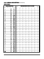
2.2.6 ARMING CODE SETTINGS (continued)
Switch SW-A
ARMING CHARACTERS
ASCII
US
CTRL
_
HEX
ARMING CHARACTER SWITCH POSITIONS
DECIMAL
LSB
1
2
3
4
5
6
7
MSB
8
O
O
O
O
O
C
C
C
1F
31
SPACE
2Ø
32
C
C
C
C
C
O
C
C
!
21
33
O
C
C
C
C
O
C
C
“
22
34
C
O
C
C
C
O
C
C
#
23
35
O
O
C
C
C
O
C
C
$
24
36
C
C
O
C
C
O
C
C
%
25
37
O
C
O
C
C
O
C
C
&
26
38
C
O
O
C
C
O
C
C
‘
27
39
O
O
O
C
C
O
C
C
(
28
4Ø
C
C
C
O
C
O
C
C
)
29
41
O
C
C
O
C
O
C
C
.
2A
42
C
O
C
O
C
O
C
C
+
2B
43
O
O
C
O
C
O
C
C
‘
2C
44
C
C
O
O
C
O
C
C
-
2D
45
O
C
O
O
C
O
C
C
.
2E
46
C
O
O
O
C
O
C
C
/
2F
47
O
O
O
O
C
O
C
C
Ø
3Ø
48
C
C
C
C
O
O
C
C
1
31
49
O
C
C
C
O
O
C
C
2
32
5Ø
C
O
C
C
O
O
C
C
3
33
51
O
O
C
C
O
O
C
C
4
34
52
C
C
O
C
O
O
C
C
5
35
53
O
C
O
C
O
O
C
C
6
36
54
C
O
O
C
O
O
C
C
7
37
55
O
O
O
C
O
O
C
C
8
38
56
C
C
C
O
O
O
C
C
9
39
57
O
C
C
O
O
O
C
C
:
3A
58
C
O
C
O
O
O
C
C
;
3B
59
O
O
C
O
O
O
C
C
<
3C
6Ø
C
C
O
O
O
O
C
C
=
3D
61
O
C
O
O
O
O
C
C
>
3E
62
C
O
O
O
O
O
C
C
Page 16 of 27
Rev L. 09/10
2.2.6 ARMING CODE SETTINGS (continued)
Switch SW-A
ARMING CHARACTERS
ASCII
CTRL
HEX
DECIMAL
LSB
1
ARMING CHARACTER SWITCH POSITIONS
2
3
4
5
6
7
MSB
8
?
3F
63
O
O
O
O
O
O
C
C
@
4Ø
64
C
C
C
C
C
C
O
C
A
41
65
O
C
C
C
C
C
O
C
B
42
66
C
O
C
C
C
C
O
C
C
43
67
O
O
C
C
C
C
O
C
D
44
68
C
C
O
C
C
C
O
C
E
45
69
O
C
O
C
C
C
O
C
F
46
7Ø
C
O
O
C
C
C
O
C
G
47
71
O
O
O
C
C
C
O
C
H
48
72
C
C
C
O
C
C
O
C
I
49
73
O
C
C
O
C
C
O
C
J
4A
74
C
O
C
O
C
C
O
C
K
4B
75
O
O
C
O
C
C
O
C
L
4C
76
C
C
O
O
C
C
O
C
M
4D
77
O
C
O
O
C
C
O
C
N
4E
78
C
O
O
O
C
C
O
C
O
4F
79
O
O
O
O
C
C
O
C
P
5Ø
8Ø
C
C
C
C
O
C
O
C
Q
51
81
O
C
C
C
O
C
O
C
R
52
82
C
O
C
C
O
C
O
C
S
53
83
O
O
C
C
O
C
O
C
T
54
84
C
C
O
C
O
C
O
C
U
55
85
O
C
O
C
O
C
O
C
V
56
86
C
O
O
C
O
C
O
C
W
57
87
O
O
O
C
O
C
O
C
X
58
88
C
C
C
O
O
C
O
C
Y
59
89
O
C
C
O
O
C
O
C
Z
5A
9Ø
C
O
C
O
O
C
O
C
[
5B
91
O
O
C
O
O
C
O
C
\
5C
92
C
C
O
O
O
C
O
C
]
5D
93
O
C
O
O
O
C
O
C
^
5E
94
C
O
O
O
O
C
O
C
Page 17 of 27
Rev L. 09/10
2.2.6 ARMING CODE SETTINGS (continued)
Switch SW-A
ARMING CHARACTERS
ASCII
CTRL
HEX
DECIMAL
ARMING CHARACTER SWITCH POSITIONS
LSB
1
2
3
4
5
6
7
MSB
8
_
5F
95
O
O
O
O
O
C
O
C
`
6Ø
96
C
C
C
C
C
O
O
C
a
61
97
O
C
C
C
C
O
O
C
b
62
98
C
O
C
C
C
O
O
C
c
63
99
O
O
C
C
C
O
O
C
d
64
1ØØ
C
C
O
C
C
O
O
C
e
65
1Ø1
O
C
O
C
C
O
O
C
f
66
1Ø2
C
O
O
C
C
O
O
C
g
67
1Ø3
O
O
O
C
C
O
O
C
h
68
1Ø4
C
C
C
O
C
O
O
C
i
69
1Ø5
O
C
C
O
C
O
O
C
j
6A
1Ø6
C
O
C
O
C
O
O
C
k
6B
1Ø7
O
O
C
O
C
O
O
C
l
6C
1Ø8
C
C
O
O
C
O
O
C
m
6D
1Ø9
O
C
O
O
C
O
O
C
n
6E
11Ø
C
O
O
O
C
O
O
C
o
6F
111
O
O
O
O
C
O
O
C
p
7Ø
112
C
C
C
C
O
O
O
C
q
71
113
O
C
C
C
O
O
O
C
r
72
114
C
O
C
C
O
O
O
C
s
73
115
O
O
C
C
O
O
O
C
t
74
116
C
C
O
C
O
O
O
C
u
75
117
O
C
O
C
O
O
O
C
v
76
118
C
O
O
C
O
O
O
C
w
77
119
O
O
O
C
O
O
O
C
x
78
12Ø
C
C
C
O
O
O
O
C
y
79
121
O
C
C
O
O
O
O
C
z
7A
122
C
O
C
O
O
O
O
C
{
7B
123
O
O
C
O
O
O
O
C
|
7C
124
C
C
O
O
O
O
O
C
}
7D
125
O
C
O
O
O
O
O
C
~
7E
126
C
O
O
O
O
O
O
C
DEL
7F
127
O
O
O
O
O
O
O
C
Page 18 of 27
Rev L. 09/10
SECTION 3 – OPERATION
3.1
POWERING THE UNIT
When power is first applied, note the status of the right decimal point on the Port
Display. The right decimal point should indicate a steady ON (illuminated) state. If the
right decimal point blinks, refer to Troubleshooting, section 3.8.
3.1.1
FRONT PANEL INDICATORS
The 7-segment Port Display exhibits the selected port; the LED’s monitor the status
of data and control handshake on pins 2 – 6, 8 & 20 of the Master Port - status of
the pins are displayed with or without power applied to the i-COS. Indications are as
follows:
Function
Switch
Time
ST
Lock-Out
LO
Data
2, 3
Control
Handshak
e
Port
Selected
Power-on
Status
7-SEGMENT PORT
DISPLAY *
LED INDICATIONS
4 – 6, 8, 20
-- --- --
RED = Active
OFF = Inactive
RED = Active
OFF = Inactive
RED = Active (+) signal
GREEN = Inactive ( - ) signal
OFF = No signal
Port 0 – 3 = “0 – 3”
“L”
-- --
GREEN = Active (+) signal
RED or OFF = No signal
-- --
-- --
Port 0 – 3 = “0 – 3”
-- --
Right decimal:
ON = Power Good
OFF = RESET
BLINKING = Error
* See chart in section 3.9 for i-COS/8, /12 & /16
3.2
ARMING CHARACTER & PORT SELECT CHARACTER
The arming and port addressing code consists of two characters in the form:
arm_addr; where,
arm represents the arming character, and addr represents the port
select character.
The arming character initiates Switch Time, and is immediately followed by the
address character, which assigns the port. Any port can switch the port when the
unit is in Switch Time, unless disabled by SW-T position 6. The arming and switching
code is stripped by the Code Operated Switch. The Arming character can pass as
data in Graphics mode.
Page 19 of 27
Rev L. 09/10
ARMING CHARACTER
This character is user selected and entered via DIP switch SW-A (See chart in
paragraph 2.2.6). The arming character may be set as the equivalent of an
ASCII, CTRL, HEX or Decimal character. For example, the arming character may
be any one of the following CTRL characters: @, A, B, C, D, E.
When the i-COS receives the arming character within the data stream, it will
enter an armed state known as Switch Time, and the “ST” LED on the front
panel will be illuminated.
PORT SELECT CHARACTER
The port select character is the first character received after the arming
character, and determines which Subordinate Port will be selected – the port
select character can only be recognized as such by its position in the data
stream.
With the PORT16 switch (SW-C, position 8), set False (Closed), only the least
significant four bits are used in the decoding. Therefore, port selection is limited
to Port 0 through Port 7. For example, for ports 0 – 3, the port select character is
ASCII 0 through 3 (30 HEX through 33 HEX). Reference the charts in paragraph
2.2.6 and paragraph 3.9.
With the PORT16 switch set True (Open), all eight bits are used in the decoding.
Therefore, port selection is enabled for all ports 0 through 15.
3.3
COMMUNICATION ERROR CONDITIONS
Under normal conditions where no communication errors are detected, the Port
Display provides the normal indications as shown in paragraph 3.1.1 above.
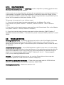
When an error is detected, the Port Display is multiplexed to show the port address
for approximately one second, and then an error symbol (Figure 3–1 below). This
alternating display remains for approximately five seconds and then returns to the
normal display, providing that there are no additional errors detected.
LO
FE_M OE_M PE_M TE_M
M-Port Errors:
Framing, Overflow, Parity & Transmit
FE-S
O E-S
PE-S
TE-S
S-Port Errors :
Framing, Overflow, Parity & Transmit
Figure 3–1. Port Display Error Indications
Page 20 of 27
Rev L. 09/10
3.4
AUTO TIME OUT
If Auto Timeout is enabled, the i-COS will time out after an idle time as selected by
switch SW-T, and return to Switch Time. Data in either direction will continually reset
the timer. To disable Auto Timeout, set the time to “infinite”.
NOTE
If AUTO TIMEOUT is selected, the unit will revert
to Switch Time after the selected timeout.
3.5
RESET BUTTON
The reset button will force the unit into Switch Time or to a Port, as selected by
Switch-P (reference page 14).
3.6
LOCK-OUT
When the unit is in Lock-Out, the front panel “LO” LED will illuminate, and the Port
Display will indicate the letter “L”. The Subordinate Ports can not access the Master
Port. Lock-Out is controlled exclusively by the Master Port. The i-COS can be put into
Lock-Out during the Switch Time when:
For COS/4 and /8 units: SW-C, pos 8 Closed, and a 38 HEX (or greater) character is
transmitted at the Master Port.; For COS/12 and /16 units: SW-C, pos 8 Open, and a
70 HEX (or greater) character is transmitted at the Master Port.
To get out of Lock-Out, transmit the arming character. When emerging from LOCKOUT, both the LO and ST LEDs will be lit until a port is selected; Port Display is
blanked.
3.7
MODES OF OPERATION
The i-COS can operate in one of three modes: TEXT, TRANSPARENT, or GRAPHICS.
The MODE front panel toggle switch is used to select the desired mode.
3.7.1 TEXT MODE
(UP switch position) In the TEXT mode, the i-COS will enter Switch Time whenever it
receives an arming character. The unit will select the Subordinate Port that is
specified by the port select character. The remaining text will pass through the unit
until another arming character is encountered. The arming character and the port
select character will not pass through the unit in this mode. It is the user’s
responsibility to choose an arming character that will never appear as part of the text.
3.7.2 TRANSPARENT MODE
(MIDDLE switch position) In the TRANSPARENT mode, all data including the
arming and port selection character will pass through the unit to and from the Master
and the Subordinate Ports that were selected before entering this mode. This mode
totally disables code control, and all characters printable and non-printable are
passed.
Page 21 of 27
Rev L. 09/10
3.7.3 GRAPHICS MODE
(DOWN switch position) The GRAPHICS mode is capable of passing graphics data
while still maintaining code control.
In this mode, an arming character will only be recognized as an arming character if it
is preceded by a pause in data transmission of a required minimum length of time,
user selected via SW-P, positions 5 and 6. Any arming character not preceded by this
pause will be passed as data (see Section 2.2.5).
This pause is measured in one of three ways:
1. From the time the last character was sent from the Master Port to the
Subordinate Port (SW-P Position 7 CLOSED, Position 8 OPEN – refer to Section
2.2.5).
2. From the time the last character was sent from the Subordinate Port to the Master
Port (SW-P Position 7 OPEN, Position 8 CLOSED).
3. From the time the last character was sent in either direction (SW-P Position 7
CLOSED, Position 8 CLOSED). To disable the pause reset, set SW-P positions 7 and 8
OPEN.
3.8
TROUBLESHOOTING
Blinking Decimal Point — a blinking right decimal point on the Port Display indicates
the ASIC has failed to load from the PROM. Power down the unit, wait for a few
seconds then power on again. If the decimal point continues to blink, return the unit
for analysis.
Unit Switches On Its Own — If the i-COS appears to switch on its own, it is most likely
receiving an arming character in the data stream. If the switching control should only
come for the Master Port or only come from the Subordinate Port, disable the port
which is not being used for switching (SW-T Positions 3 thru 6 – See paragraph
2.2.2), or try running GRAPHICS mode.
Bit Loss — If occasional bit loss occurs, try running 2 stop bits on the computer
equipment (with the i -COS unit set to receive 1 stop bit).
Will Not Pass Data/Will Not Switch — If data does not pass and the i-COS will not
switch, check the cables and the port switches (SWA, SWB).
Communication Errors — Reference section 3.3.
Page 22 of 27
Rev L. 09/10
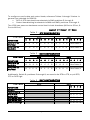
3.9
i-COS 4/8/12/16 PORT INFORMATION
The following chart indicates the Port Address Characters (also called Port Address
Codes) used to select a port. In the data stream, the Port Address Character follows
the Arming Code to select/assign the corresponding port (reference paragraph 3.2).
Port No.
0
Port Addr Character
ASCII
Hex
0
30
Numeric
Display
Board I/O
Main-0
1
1
31
Main-1
2
2
32
Main-2
3
3
33
Main-3
4
4
34
J6-0
5
5
35
J6-1
6
6
36
J6-2
7
7
37
J6-3
8
8
38
J7-0
9
9
39
J7-1
10
:
3A
J7-2
11
;
3B
J7-3
12
<
3C
J8-0
13
=
3D
J8-1
14
>
3E
J8-2
15
?
3F
J8-3
Page 23 of 27
Rev L. 09/10
3.10 BASIC TEST PROGRAM FOR THE i-COS
Connect the PC to the Master Port and run the following program using either BasicA
or GW Basic.
10 REM*************** CODE ACTIVATED SWITCH TEST ******************
20 OPEN “COM1: 9600,N,8,1,CS,DS” AS1
:REM** SET UP COM 1 PC PORT**
30 P=48
:REM**SET PORT # TO 1(DECIMAL 48)**
40 PRINT #1, CHR$(4);
:REM**SEND ARMING CHAR**
50 PRINT #1, CHR$(P);
:REM**SEND PORT # OUT COM 1 **
60 T=P-48
:REM**CONVERT DEC. TO ACTUAL PORT # **
70 PRINT #1, “THIS IS A TEST OF PORT#”T
:REM**SENDS MESSAGE OUT COM 1**
80 FOR I=I TO 250
:REM**DELAY **
90 NEXT I
:REM**LOOP**
100 P=P+1
:REM**INCREMENT PORT # **
110 IF P=52 THEN GOTO 30 ELSE GOTO 40
:REM**LOOP BACK FOR NEXT PORT**
NOTE
REM statements are optional. Semi- colons are required at the end of lines 40 and
50 to inhibit CR.
NOTES
Page 24 of 27
Rev L. 09/10
NOTES
Page 25 of 27
Rev L. 09/10
EIA-CITT MODEM TABLE (DCE) – TERMINAL (DTE) – INTERFACE
PIN
1
2
3
4
5
6
7
8
9
10
11
12
13
14
15
16
17
18
19
20
21
22
23
24
25
NAME DTE DCE
FG
TD
RD
RTS
CTS
DSR
SG
DCD
QM
(S)DCD
(S)CTS
(S)TD
NC
TC
(S)RD
DCT
RC
DCR
(S)RTS
DTR
SQ
RI
(TC)
FUNCTION
FRAME GROUND
TRANSMITTED DATA
RECEIVED DATA
REQUEST TO SEND
CLEAR TO SEND
DATA SET READY
SIGNAL GROUND
DATA CARRIER DETECT
POSITIVE DC TEST VOLTAGE
NEGATIVE DC TEST VOLTAGE
EQUALIZER MODE
SEC. DATA CARRIER DETECT
SEC. CLEAR TO SEND
SEC. TRANSMITTED DATA
NEW SYNC
TRANSMITTER CLOCK
CCITT
CIRCUIT
(EIA)
101
103
104
105
106
107
102
109
(AA)
(BA)
(BB)
(CA)
(CB)
(CC)
(AB)
(CF)
BELL
122
121
118
BELL
114
208A
(SCF)
(SCB)
(SBA)
208A
(DB)
DIVIDED CLOCK TRANSMITTER BELL
RECEIVER CLOCK
115
DIVIDED CLOCK, RECEIVER
BELL
SEC. REQUEST TO SEND
120
DATA TERMINAL READY
108.2
SIGNAL QUALITY DETECT
110
RING INDICATOR
125
DATA RATE SELECTOR
111
DATA RATE SELECTOR
112
EXT. TRANSMITTER CLOCK
113
BUSY
208A
(DD)
208A
(SCA)
(CD)
(CG)
(CE)
(CI)
(DA)
POSITIVE VOLTAGE EQUALS A BINARY “ZERO” OR A SIGNAL “SPACE” OR A
CONTROL SIGNAL “ON”
NEGATIVE VOLTAGE EQUALS A BINARY “ONE” OR A SIGNAL “MARK” OR A
CONTROL SIGNAL “OFF”
GRAY ON THIS TABLE INDICATES “NOT USED”
Page 26 of 27
Rev L. 09/10
LIMITED WARRANTY
RelComm, Inc., hereafter referred to as RCI, warrants this Product to be in good
working order for a period of One (1) Year from the date of purchase from RCI. NO
WARRANTIES, WHETHER EXPRESS OR IMPLIED, WILL APPLY AFTER THIS PERIOD.
Should this Product fail to be good working order at any time during this warranty
period, RCI will, at its option, repair or replace this product at no additional charge
except as set forth below. Repair parts and replacement Products will be furnished
on an exchange basis and will be either reconditioned or new. This limited warranty
does not include service to repair damage to the Product resulting from accident,
disaster, misuse, abuse, or non-RCI modification of the Product.
Limited Warranty service may be obtained by delivering the Product during the
warranty period to RCI and providing proof of purchase date. If this Product is
delivered by mail, you agree to:
a)
insure the Product or assume the risk of loss or damage in transmit,
b)
prepay shipping charges to the warranty service location, and
c)
re-use the original shipping container or equivalent.
SOME STATES DO NOT ALLOW LIMITATIONS ON HOW LONG AN IMPLIED WARRANTY
LASTS, SO THE ABOVE LIMITATIONS MAY NOT APPLY TO YOU.
IF THIS PRODUCT IS NOT IN GOOD WORKING ORDER AS WARRANTED ABOVE, YOUR
SOLE REMEDY SHALL BE REPAIR OR REPLACEMENT AS PROVIDED ABOVE. IN NO
EVENT WILL RCI BE LIABLE TO YOU FOR ANY DAMAGES, INCLUDING ANY LOST
SAVINGS OR OTHER INCIDENTAL OR CONSEQUENTIAL DAMAGES ARISING OUT OF
THE USE OF OR INABILITY TO USE SUCH PRODUCT, EVEN IF RCI OR AN AUTHORIZED
DEALER HAS BEEN ADVISED OF THE POSSIBILITY OF SUCH DAMAGES, OR ANY CLAIM
BY ANY OTHER PARTY.
SOME STATES DO NOT ALLOW THE EXCLUSION OR LIMITATION OF INCIDENTAL OR
CONSEQUENTIAL DAMAGES FOR CONSUMER PRODUCTS, SO THE ABOVE
LIMITATIONS OR EXCLUSIONS MAY NOT APPLY TO YOU.
THIS WARRANTY GIVES YOU SPECIFIC LEGAL RIGHTS, AND YOU MAY ALSO HAVE
OTHER RIGHTS WHICH MAY VARY FROM STATE TO STATE.
For further information, contact:
on the Web: www.relcomm.com
RelComm Service
P.O. Box 640
4868 highway 4, Suite G
Angels Camp, CA 95222
Email: [email protected]
Phone: (209) 736-0421
FAX:
(209) 736-0425
Toll-Free: (800) 222-2810
Page 27 of 27
Rev L. 09/10