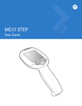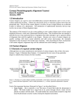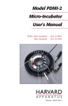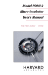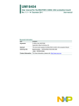
1
3D Perfusion Bioreactor™
User Manual and 3D Cell Perfusion Handbook
Version 1.4, Updated 12.1.2014
1
Note
This manual will be revised and updated without prior notice. To check if the latest
version comes with your 3D Bioreactor System, please visit our website at
http://www.3dbiotek.com/web/prod_3dbioreactor.aspx
Registration
Registration of your purchase is recommended in order to receive product update and
promotional discount code for PS/PCL scaffolds specifically made for use in our 3D
Bioreactor. Please follow the link below to register.
http://www.3dbiotek.com/web/register4bioreactor.aspx
Version 1.4, Updated 12.1.2014
2
Contents
1.
3D Perfusion Bioreactor™ Overview ............................................................................................4
2.
3D Insert™ Technology ...............................................................................................................5
3.
3D Perfusion Bioreactor: Parts and Assembly ..............................................................................6
3.1
3D Perfusion Bioreactor Parts List ........................................................................................7
3.2
Perfusion Bioreactor Assembly ............................................................................................8
4. Cell Culture: Static Cell Seeding and Dynamic Cell Culture..............................................................11
4.1
Direct Static Cell Seeding into Bioreactor Chamber .............................................................12
5. Perfusion Velocity and Revolution per Minute (RPM) Graph and Table ..........................................16
6. Pump Tubing Sterilization ............................................................................................................16
7. Tubing Connection Circuit Diagram ..............................................................................................16
8.
Appendix ..................................................................................................................................19
8.1
Pre-Installation Check List..................................................................................................19
8.2
Pump’s Power Cord Through Incubator’s Double Doors .....................................................20
For Latest Updates on the Bioreactor Manual, Please Visit our Website at
http://www.3dbiotek.com/web/prod_3dbioreactor.aspx
Version 1.4, Updated 12.1.2014
3
1. 3D Perfusion Bioreactor™ Overview
Congratulations on the purchase of this 3D perfusion bioreactor!
This bioreactor is specifically designed for conducting physiology relevant cell culture in a 3D in vivo-like
microenvironment under dynamic perfusion conditions.
This bioreactor has integrated our proven 3D Insert technology with a unique dynamic perfusion system
to allow mammalian cells to grow in a 3D in vivo-like micro-environment. Users will obtain the following
distinct advantages by using this 3D perfusion bioreactor.
1.
Wide range of 3D surface areas for initial cell seeding
3D Perfusion Bioreactors are available in different configurations that provide cell growth area
from 9.5 cm2 to 3960 cm2, wide enough to meet various lab research needs.
2.
Compatible with wide range of 3D InsertTM scaffolds
A very unique feature about the 3D Perfusion Bioreactor is that a wide range of 3D InsertTM
scaffolds, from 24 well to 6 well configurations, can be used in the bioreactor, all with a simple
change of a chamber.
3.
Autoclavable
All parts and tubing (except pump) are autoclavable.
4.
Forced CO2 and O2 exchange to maintain better cell growth environment
CO2 and O2 are forced to bubble through the cell culture medium to better maintain an ideal cell
culture environment.
5.
Adjustable medium flow rate to better meet individual needs
Medium perfusion flow rate can be adjusted to meet individual needs. This also makes it
possible to study the flow rate or shear force effects on cell growth. The pump’s digital display
and control make it easier to adjust the flow rate.
Version 1.4, Updated 12.1.2014
4
2. 3D Insert™ Technology
One of the novelties of the 3D Bioreactor is the 3D InsertTM porous polymer scaffolds that sit inside the
bioreactor chambers. The 3D scaffold is engineered using 3D Biotek’s Proprietary Precision
Microfabrication Technology. Unlike other sponge like porous scaffolds, the porous 3D InsertTM scaffolds
have 100% open and interconnected pores, therefore, cell culture medium can easily perfuse through
the porous structure to eliminate the poor nutrient/waste exchange phenomena often encountered
with sponge-like scaffolds. The scaffolds are available in both biodegradable and non-biodegradable
polymers. The entire scaffold is composed of polymer struts of uniform size. Struts on different layers of
the scaffold are 90o relative to each other creating a 3-dimensional and 100% interconnected porous
structure (Figure 1).
Other important features of the 3D scaffolds:
•
•
•
•
•
Pre-sterilized and Ready to Use
Well Defined Pore and Porous Structure
Improved Cell Culture Efficiency
Easy Separation of Cytokines and Secreted Growth Factors
Produced from an Organic solvent Free Fabrication Process
Figure 1. CAD images of 3D InsertTM – PS scaffold. Different color struts represent different layering in
the scaffold. This 4-layered model shows a top view (a) and (b) and side view (C) shows from bottom to
top, layer 1 (Green), layer 2 (Yellow), layer 3 (Aquamarine), and layer 4 (Red). Each layer is 90° and offset
in reference to each other.
Version 1.4, Updated 12.1.2014
5
3. 3D Perfusion Bioreactor: Parts and Assembly
Note: The 3D Perfusion Bioreactor is designed to use within a cell culture incubator at 37oC.
Please do not use the pan humidifier of the incubator because the pump is not designed for
use in a high humidity environment. The bioreactor comes with its own humidifier to reduce
the evaporation of the cell culture medium.
The 3D Perfusion Bioreactor consists of 4 independent autoclavable polycarbonate chambers. The
chambers are available in different sizes to accommodate 3D Insert™ of 24, 12, and 6-well
configurations. An 8-channel peristaltic pump, which has an adjustable speed range from 0 to 60 RPM,
to recirculate cell culture medium through the 4 cell culture chambers at the same time.The system is
equipped with a build-in CO2 humidifier system that constantly pumps CO2/O2 directly into the cell
culture media.
Figure 2 and Table 1 give a detailed list of part number and description of all individual components of
the 3D Perfusion Bioreactor.
Figure 2. Illustration of bioreactor Parts. Bioreactor’s max dimensions Width (X) ~14”, Depth (Y) ~13”,
and Height ~12”(Z).
Version 1.4, Updated 12.1.2014
6
3.1. 3D Perfusion Bioreactor Parts List
Table 1. Catalog number and description of 3D Perfusion Bioreactor Parts
Item#
Part#
Description
1
3DB-10-01 Peristaltic Pump with 8 channels.
2
3DB-10-02 Aluminum Base Frame.
3
3DB-10-03 Aluminum stand for holding 4 bioreactor chambers (item# 4), 4 glass reservoirs (item# 7) & 4 small
humidifier glass bottles (item# 10).
4
3DB-10-04 Bioreactor Polycarbonate Chambers (4)
5
3DB-10-05 Silicon Rubber O-rings (11/chamber x 4 chambers) to separate individual scaffolds within the
chamber.
6
3DB-10-06 Pre-packagedsets of tubing (4) to close-loop the chambers with the media reservoir and Co2
humidifier glass bottle through the pump. Each packaged sethas 2 pre-assembled tubing for media
and CO2 perfusion and 3 pieces of clear tubing (1 mid-size with white stoppers on one end and 2
short tubing pieces for the air filters. There are additional barbed tube fittings (5) for connecting
bioreactor tubing circuitry during bioreactor equilibration.
7
3DB-10-07 Glass cell culture medium reservoir (4).
8
3DB-10-08 Cap with fittings (4) for glass cell culture medium reservoir.
9
3DB-10-09 Syringe Filter (0.20um) (3DB-10-07)(item# 12).
10
3DB-10-10 Co2 Humidifier glass bottle (4). Humidified CO2 is pumped into the medium reservoir (item# 7).
11
3DB-10-11 Cap with fittings (4) for Co2 Humidifier glass bottle (item# 10).
12
3DB-10-12 PS or PCL scaffolds (40) (not included) for selected chamber size.
13
3DB-10-A1 Accessory: Chamber stand (4) for holding the bioreactor chamber while loading 3D scaffolds.
14
3DB-10-A2 Accessory: Scaffold/O-ring pusher(1) for loading scaffolds and O-rings into the bioreactor chamber.
15
3DB-10-A3 Accessory: Regular forceps (1) for scaffolds and O-ring loading into the bioreactor chamber.
Version 1.4, Updated 12.1.2014
7
3.2.
Perfusion Bioreactor Assembly
Note: All 3D Perfusion Bioreactor parts, except peristaltic pump, need to be autoclaved
before any experiment. The autoclavable parts can be autoclaved using autoclaving bags at
121°C for 30 minutes and 30 minutes drying. The bioreactor tubing and syringe filters are
autoclavable 5 cycles maximum.
For further technical questions on autoclavable syringe filters, visit Millipore’s Technical
Library at http://www.millipore.com/search.do?q=SLFG02550#0:0
The position of reservoir bottles need to be organized as 1, 2, 3, and 4 starting from left to right when
assembling the 3D Perfusion Bioreactor (Please refer to Figure 2A). The perfusion bioreactor assembly
has been optimized to achieve media equilibration and bioreactor chamber static cells seeding at the
same time. These two steps are required for final 3D perfusion.
Each non-sterile pre-assembled tubing set comes with different lengths to account for the positions of
the media reservoir and humidifier bottles on the aluminum metal stand. Make sure you don’t mix all
the different pre-assembled pump tubing before or after an experiment.
1
2
3
4
Figure 2A. Designation of Bottle Location13
Autoclaving of all the parts, except the pump and 3D InsertTM scaffolds, is needed before assembling the
bioreactor system because the polycarbonate chambers (4), tubing, fittings, Co2 humidifier bottles, and
Version 1.4, Updated 12.1.2014
8
media reservoir bottles are non-sterile. Before autoclaving, mark the autoclaving bags containing the
tubing with the number associated to the position of the media reservoir bottle to avoid tubing
mismatch. Assembly of the Perfusion Bioreactor should be done in a sterile hood. Refer to figure 2 for
visual description of bioreactor tubing assembly:
1. Wipe the sterile hood surface with 70% ethanol prior to assembly and let the hood surface air
dry.
2. Place all the sterile parts inside the hood. Wipe the aluminum stand holder, pump and pump’s
cassettes (Unlock the cassette channels from the pump by clicking downward on the oval
mound on each cassette (distal end of the cassette) with 70% Ethanol. Insert the aluminum
stand holder into the aluminum base frame (Refer to Figure 2 for assembly). Media reservoir
bottles (item 7) should be placed in the front of the aluminum stand holder (item 3).
3. Place the Co2 humidifier chambers (item 11) on the back holders in the aluminum stand. Fill
each humidifier bottle with 25-ml of sterile water.
4. 3D Perfusion Tubing Bioreactor Description. From this point on refer to figure 3 for assembly of
media and CO2/O2 tubing. The tubing has been labeled with autoclavable color tape to match
with the imprinted letter on the media reservoir (Red (R), Orange (O), Yellow (Y), Green (G)) and
Co2 humidifier metal caps (Green (G) and B (Blue)). Start tubing assembly with reservoir bottle 1
(from left to right). Spray the autoclave bags and bottles with 70% ethanol and wipe. Below is
an itemized description of the tubing, followed by detailed description on tubing assembling.
o
o
o
Pre-assembled Bioreactor Chamber Medium Loop. This tubing is composed of small
clear tubing, orange-labeled on one end (Orange arrow (Fig. 3)). This piece is attached
to beige bioreactor tubing (Dotted black lines (Fig. 3)), which connects to large clear
tubing (Black arrow (Fig. 3)) with red media stoppers on one end (Media In towards
bioreactor chamber). As pre-assembled tubing, the Media In towards bioreactor
chamber (Red solid line, Fig. 3) is connected to medium size clear tubing using a large
plastic tube fitting. The medium size clear tubing has white media stoppers and redlabeled at the end. This will connect to the media reservoir cap (Red arrow (Fig. 3)).
Pre-assembled Reservoir CO2/O2 In. This tubing is composed of small blue-labeled end
clear tubing connecting the humidifier cap (Blue arrow (Fig.3)). This piece is attached to
beige bioreactor tubing (Dotted black lines (Fig. 3)), which connects to large greenlabeled clear tubing connecting to the media reservoir cap (Green arrow (Fig. 3)).
CO2/O2Filters. Short Clear Tubing to attach Syringe Filters (Yellow and Green solid lines
with circle ends (Fig. 3)).
5. The following is the methodology to assemble and connect all bioreactor tubing.
6. Bioreactor Cell Culture Media Loop: connect the orange-labeled end of the tubing to the letter
O (Orange) on the media reservoir cap. Secure the tubing using the left metal hook. Unhook
cassette number 1, the oval mound always on the opposite side. Each cassette has an internal
channel where the beige tubing will pass through. The beige pump tubing has two plastic
stoppers. The first stopper secures the tubing on one end. Following, place the tubing through
Version 1.4, Updated 12.1.2014
9
7.
8.
9.
10.
11.
12.
the internal channel. Then, the second stopper will secure the beige tubing at the distal end. At
this point, the beige tubing should be under tension. Place the cassette back into the pump,
hooking the proximal side (opposite to the oval mound) first and then pressing down at the oval
end until there is a clicking sound. Bring the remaining length of the tubing from the back to the
front, towards the media bottle reservoir. First secure the tubing on the right hook on the metal
stand. Second, pass the tubing through the bioreactor holder hoop. Then, connect the red
taped end with the letter R (Red) on the media bottle reservoir. This completes the medium
loop without the bioreactor chamber. Later, the bioreactor chamber will replace the large
plastic tube fitting connecting the Media into Bioreactor and Media out to Reservoir Bottle.
Bioreactor CO2/O2 Gas Loop: connect the blue-labeled end of the tubing to the letter B (Blue) on
the humidifier bottle. Unhook cassette number 2 (following cassette, next to media perfusion
tubing), pressing the oval mound always on the opposite side. Each cassette has an internal
channel where the beige tubing will pass through. The beige pump tubing has two plastic
stoppers. The first stopper secures the tubing on one end. Following, place the tubing through
the internal channel. Then, the second stopper will secure the beige tubing at the distal end. At
this point, the beige tubing should be under tension. Place the cassette back into the pump,
hooking the proximal side (opposite to the oval mound) first and then pressing down at the oval
end until there is a clicking sound. Bring the remaining of the tubing from the back to the front,
towards the media bottle reservoir. Pass the tubing through the right metal hook, connecting
the green-labeled end with the letter G (Green) on the media reservoir. This completes the
Bioreactor CO2/O2 Loop; humidified CO2/O2 will be actively pumped from the humidifier bottle
to the media reservoir bottle during perfusion.
CO2/O2 Filters: the remaining short clear tubing, i.e. yellow and green-labeled, place a 0.20-um
pore syringe filter on each end and connect the color-labeled end to the media reservoir and
the humidifier bottles, yellow (Y) on media reservoir bottle and blue (B) on humidifier bottle.
Repeat steps 6 through 8 for the remaining bioreactor bottles from left to right or 1 to 4.
After connecting all tubing, fill the media reservoir bottles with cell culture media (Media bottle
max. volume 90-ml). Table 2 gives approximate values of bioreactor chamber and media
perfusion tubing pre-loading volumes. This take into account the extra volume to add, in
addition to media for extended cell culture conditions.
Remove the silicon stoppers and place on sterile surface. Using a pipette draw desired amount
of media and dispense into the media reservoir bottle. After completion, wipe the rim of the
media orifice and the silicon stopper with 70% ethanol.
Place the silicon stopper tightly into the media reservoir orifice.
Table 2. Approximate volume required to fill each bioreactor chamber format and tubing
Chamber/Tubing
Total Volume
6-Well
45-ml
12-Well
15-ml
24-Well
7.0-ml
Tubing
5.0-ml
Version 1.4, Updated 12.1.2014
10
13. At this point, the bioreactor is ready for media equilibration. Place the bioreactor into a
humidity-free incubator and set the pump to 20 rpm. While the media equilibrates, the next is
to seed cells into the bioreactor chamber following with 3 hours static seeding.
Figure 3. Tubing loop Assembly.
4. Cell Culture: Static Cell Seeding and Dynamic Cell Culture
A successful 3D dynamic cell culture using 3D Perfusion Bioreactor requires the following steps:
1.
2.
3.
4.
Media Equilibration prior to 3D Perfusion
3D Bioreactor Cell Seeding
Short Term Slow 3D Perfusion
Extreme aseptic conditions
Figure 4 is a suggested time line for conducting a 3D cell culture experiment using 3D Perfusion
Bioreactor.
Version 1.4, Updated 12.1.2014
11
Figure 4. Time line for a successful perfusion bioreactor cell culture.
While the media equilibrates in the bioreactor, there are general steps to successfully set up a 3D
dynamic culture cell system.
4.1. Direct Static Cell Seeding into Bioreactor Chamber
1. Depending on the seeding density of the experiment, cells need to be expanded under regular
tissue culture conditions. Tables 3 and 4 show the different surface areas of the 3D Insert as a
function of scaffold format, fiber diameter, and fiber-to-fiber configurations. These tables help
determine the seeding density on 3D scaffolds from already established 2D seeding densities
into seeding densities.
2. Follow standard protocols for cell detachment and cell counting. Make sure the total cell
suspension volume is scaled up for your specific cell number needs and 3D Biotek’s suggested
seeding volume. Refer to Table 5 for seeding volume values.
3. Once cells are in suspension, take the bioreactor chamber and seal the bottom with the
provided short clear tubing with a stainless steel ball. Then, place the bioreactor chamber on the
chamber stand (#13). On the opening of the bioreactor chamber cap place another small clear
tubing, following with a 0.20-um air syringe filter. These will prevent any potential
contamination in transit to the incubator and during the three-hour incubation period.
4. Using the forceps, pick an O-ring and place it on the base of the bioreactor chamber. Using the
O-ring pusher, slide the O-ring evenly using rotating motion until it reaches the bottom of the
bioreactor chamber.
5. Next, grab a 3D Insert™ scaffold using the appropriate forceps along the scaffold’s diameter and
from the easy-handle sides (small cut outs for stable scaffold grip). Slide without releasing the
scaffold until it evenly touches the first O-ring at the bottom. Release the forceps and retract
them from the chamber.
6. Take another O-ring and repeat step 4.
Version 1.4, Updated 12.1.2014
12
7. Using the pipette, aliquot the correct volume (Table 5) containing the specified number of cells.
Center the pipette tip and lower it carefully and gently until touching the scaffold (Do not push,
polystyrene scaffolds will break). Release the cell suspension volume. Bring the pipette tip up.
8. The previous, O-ring, scaffold, O-ring, cell seeding is a sequence that ensures minimal
disturbance to the seeded cells below for piece of mind (Figure 4 - 3D Seeding).
9. Repeat steps 5 through 7 until loading a total of 10 scaffolds and 11 O-rings for each chamber
(Figure 4 - 3D Seeding).
10. Close tight the bioreactor chamber using the bioreactor cap (make sure it has the syringe filter).
Bring the bioreactor chamber in its holder to a humidified incubator at normal culture
conditions for 3 hours static seeding.
11. After 3 hours, turn off the bioreactor and bring it out from the non-humidified incubator into
the sterile hood. Then, bring all the 3D seeded and loaded bioreactor chambers to the sterile
hood as well.
12. Before removing the large plastic fitting (Refer to Section 3.2, step 6), press the red and white
plastic stoppers on each side of the large plastic fitting before unplugging each clear tubing end.
This is to maintain constant pressure across the bioreactor.
13. Grab one bioreactor chamber; remove the bottom clear tubing with the stainless steel ball.
Secure the bioreactor chamber on the metal stand hoop and tighten using the metal slider.
14. Unhook the tubing end with the red stoppers. Then, connect it to the bottom of the bioreactor
chamber.
15. Next, remove the clear tubing with the syringe filter from the top of the bioreactor chamber.
Remove the large tube fitting from the other end of the remaining tubing (with the white
stoppers). Connect this tubing end to the top of the bioreactor chamber. At this point the
bioreactor chamber is ready for 3D perfusion (See Figure 5 to see the large tube fitting position
and bioreactor chamber for 3D perfusion (white and red asterisks)).
16. Repeat steps 12-15 for each bioreactor chamber.
Figure 4. 3D Seeding and 3D Perfusion Diagram
Version 1.4, Updated 12.1.2014
13
17. After connecting all 4 bioreactor chambers, unhook the red and white plastic stoppers (Warning:
Failure to release the stoppers will cause pressure buildup during perfusion and experimental
failure). Bring the bioreactor to a humidity-free incubator and set rpm to 1.9 to 2.1 (Figure 4, 3D
Perfusion). Press start and allow slow perfusion for 24 hours. Figure 6 and table 8 give the values
of velocities as a function of chamber format and rpm.
Figure 5. Position of tube fitting and Bioreactor Chamber
Version 1.4, Updated 12.1.2014
14
Table 3. Total surface growth area on 3D PS scaffold
Scaffold Format
2D Growth Area
24-Well
12-Well
6-Well
1.90 cm2
4.00 cm2
9.60 cm2
3D Growth Area
(PS1520)
10.20 cm2
21.08 cm2
54.02 cm2
3D Growth Area
(PS3040)
9.56 cm2
19.65 cm2
52.10 cm2
3D/2D Ratio
(PS1520)
5.4
5.3
5.6
3D/2D Ratio
(PS3040)
5.0
4.9
5.4
Table 4. Total surface growth area on 3D PCL scaffolds
Scaffold Format
2D Growth Area
24-Well
12-Well
6-Well
1.90 cm2
4.00 cm2
9.60 cm2
3D Growth Area
(PCL3030)
18.28 cm2
39.27 cm2
99.21 cm2
3D Growth Area
(PCL3050)
13.74 cm2
27.90 cm2
75.62 cm2
3D/2D Ratio
(PCL3030)
9.6
9.8
10.3
3D/2D Ratio
(PCL3050)
7.2
7.0
7.9
Table 5. Seeding volume on scaffold as a function of scaffold format
Scaffold Size
24-well
12-well
6-well
PS(1520)
60
120
300
Seeding Volume (µl)
PS(3040)
PCL(3030)
120
130
240
270
600
690
Version 1.4, Updated 12.1.2014
PCL(3050)
160
340
880
15
5. Perfusion Velocity and Revolution per Minute RPM Graph and
Table
Figure 6. Range of rmp value for a range of biologically relevant flow velocities
In figure 6, the rpm values were calculated from flow velocity of interest and the scaffold cross-sectional
area by using following equation (EQ. 1)
RPM = K x (Velocity x cross section area of scaffold)
EQ. 1
Where, K = 8.547, this is an experimentally determined constant from the linear fit between flow rate
(ml/min) and rpm for the 3D bioreactor system (R2 = 0.999).
Table 7. Cross-section Area of Scaffold as a function of format
Scaffold Format
Cross-Section cm
24-Well
1.13
12-Well
2.83
6-Well
7.07
Version 1.4, Updated 12.1.2014
2
16
Table 8. Relationship between pump’s rpm and biologically relevant flow velocities
Velocity (cm/min)
0
0.2
0.4
0.6
0.8
24-Well
rpm
0
1.93
3.86
5.8
7.73
Chamber Format
12-Well
rpm
0
4.84
9.69
14.53
19.38
6-Well
rpm
0
12.08
24.15
36.23
48.31
6. Pump Tubing Sterilization
The tubing for the pump refers to the one with 2 stops that are used with the cartridge of the pump
head. The 2 stops are attached to the tubing by adhesive (Figure 7).
Stop
Figure 7. Pump Tubing with Stops
During successive autoclave procedures under high temperature, these stops may drop off the tubing
due to failure of the adhesive. Given below are some recommended methods to sterilize this particular
tubing.
•
•
•
•
Gas sterilization with ethylene oxide
Gamma Irradiation
Autoclave at 1 BAR and 120ᵒC for 30 minutes
Flush ethanol and then rinse with cell media through the tubing using the pump
Consider that the tubing will mechanically degrade over time as it is repeatedly squeezed by the rollers.
There comes a time when it is necessary to replace the tubing independent of cleaning considerations.
Version 1.4, Updated 12.1.2014
17
7. Tubing Connection Circuit Diagram
The following diagram (Figure 8) shows the tubing connection circuit for the system, which should be
used in conjunction with the schematic diagram (Figure 3). To connect the tubing circuit for each
bottle/chamber location, also refer to Figure 2A.
Figure 8. Tubing Connection Circuit for the system
Version 1.4, Updated 12.1.2014
18
8. Appendix
8.1 – Pre-Installation Check List
Before the bioreactor system is installed, it is recommended to check if the following items are available.
•
Bioreactor Parts: all the items listed in Section 3.1 on Page 7.
•
Scaffolds: scaffolds ordered from 3D Biotek, or your own scaffolds.
•
Cells & Media: from your laboratory
•
Incubators: either option (1) or (2) below
o
(1) Tall incubation with 2 independent compartments, each with standard internal
space: 18”W x 18”D x 20+”H (see Figure 9); One compartment for Media Equilibration in
non-humidified condition and one for Static Cell Seeding in humidified condition.
o
(2) 1 standard-size incubator with single compartment (required minimum internal
space: 16”W x 15”D x 14”H) for Media Equilibration in non-humidified condition, and 1
desktop-size incubator (no minimum internal space requirement) for Static Cell Seeding
in humidified condition.
o
For the overall dimensions of the bioreactor assembly, refer to Figure 2 on Page 6.
H
D
W
Top Compartment
Door Open
Door Closed
Figure 9. Incubator with 2 independent compartments
Version 1.4, Updated 12.1.2014
19
8.2 – Pump’s Power Cord Through Incubator’s Double Doors
The following diagram (Figure 10) shows the setup of the pump’s power cord through the double doors
of the incubator.
Power Cord Thru.
Main Door
Power Cord Thru.
Glass Door
Figure 10. Pump’s Power Cord Through Incubator’s double doors
Version 1.4, Updated 12.1.2014
20