1
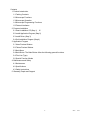
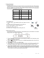
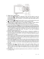
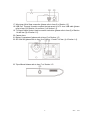
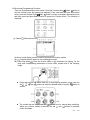
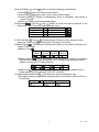
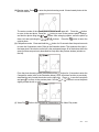
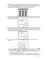
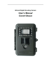
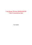
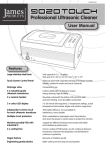
User Manual
Digital Microscope
Model MC200
Contents
1. Product Introduction
1.1 Packing Contents
1.2 Microscope Functions
1.3 Microscope Operation
1.4 Microscope Programming Functions
1.5 External Interfaces
2. Program Installation
2.1 Insert Installation CD (Step 1)
16
2.2 Install Application Program (Step 2)
2.3 Install Driver (Step 3)
2.4 Quit Installation Program (Step 4)
3. Application Program
3.1 Video Preview Window
3.2 Photos Preview Window
3.3 Main Menu
3.4 Main Button. The Main Button offers the following general functions:
3.4 Files List (Type)
3.6 Special Function Modes
4. Maintenance and Safety
4.1 Maintenance
4.2 Specifications
4.3 Safety Instructions
5. Warranty, Repair and Support
2
V2.0
7/10
1. Product Introduction
1.1 Packing Contents
The product box includes one instrument and the accessories listed below. Please charge
the lithium battery for 6 to 8 hours before using the instrument for the first time. An SD Card
has been installed in the instrument. Please refer to item (4) of Section 1.5 for instructions
on the removal and installation of SD cards.
Name
Qt Name
Qty
y
Microscope
1
Lithium Battery
1
USB Cable
1
User Guide
1
Power Adapter
1
Installation CD
1
AV Terminal
1
Protective holder 1
Cable
2G Micro SD
1
Wrist Strap
1
Card
Cleaning Cloth
1
Lens adaptors*
5
*Lens Adaptors (5):
(1) Contact cap 01: Soft materials (cloth, wool, paper, hair, skin,
etc.)
(2) Contact cap 02: SMT components, coins, disks, etc.
(3) Non-contact adaptor: Flowers, insects, etc.
(4) Deep tank: Water, rocks, etc.
(5) Shallow tank: Fish eggs, spores, sand, gems, etc.
1.2 Microscope Functions
The Microscope includes push-buttons, communication ports, and interfaces for external
storage. Refer to the following descriptions:
1. Power Supply : Press this button for two seconds to switch on the instrument; press
again to switch off the instrument.
2. Zoom Out : Use this button to zoom out on a digital image [please refer to (H) and (I) of
item (1) of Section 1.4].
3. Zoom In : Use to zoom in on a digital image.
4. RESET opening: In the event that the instrument freezes operationally (no reaction when
pressing any button), insert a paper clip into the opening to trigger the RESET button.
5. Camera/Video REC : This button is used to take a photograph in the observation mode
[please refer to item (1) of Section 1.4] and to open files in the Video Play mode [please
refer to item (2) of Section 1.4]. In Video REC mode [please refer to item (3) of Section
1.4], the button is used to start and stop recording video.
3
V2.0
7/10
6. Display Screen: Displays images.
7. Function Menu /Delete : In the observation mode, press this button to open the
Function Menu ( ). In the Photo browsing mode (Album), press this button to delete
photos [please refer to item (4) of Section 1.4]. This button is also used to delete videos in
the Video Play mode.
8. Preview Photos
/Back : Press this button to enter or exit the preview photos mode
( ). In other modes, this button moves back or exits a programming level.
9. Charging Display Lamp : Red lamp is on when battery is charging. The lamp switches
off when charging is complete [please refer to (G) of item (1) of Section 1.4].
10. Power Supply Display Lamp : Green lamp indicates that the instrument is switched on.
11. Increase Lighting Brightness : Eight (8) levels of brightness are available for adjustment
[please refer to (D) of item (1) of Section 1.4]. In the observation mode, this button is used
to increase brightness of illumination (auxiliary sources). Press and hold this button to
switch to the light mode [please refer to (B) of item (1) of Section 1.4]. Press this button to
stop playback in the Video Play mode. This button is also used for advanced
programming options described later.
12. Decrease Lighting Brightness
: Press this button to decrease the brightness of
illumination. Press and hold this button to switch the scene mode [please refer to ( c ) of
item (1) of Section 1.4]. This button is also used for advanced programming options
described later in this guide.
13. Rotate Lamp Left
: Rotate the lamp to the left. Press and hold this button to display the
center alignment grid on the monitor; press it again to switch it off [please refer to (J) of
item (1) of Section 1.4]. The button is also used for advanced programming steps in other
modes as described later in this guide.
14. Rotate Lamp Right : Rotate the lamp to the right. Press and hold this button to display
the ‘cross-hair’ alignment on the monitor; press it again to switch it off [please refer to (K)
of item (1) of Section 1.4]. The button is used to quickly play video forward in the Video
Play mode. This button is also used for advanced programming steps described later in
this guide.
15. Confirmation Button
: Momentary presses select special display effects in the
observation mode [please refer to (C) of item (1) of Section 1.4]. Press and hold this
button to switch on or off the display scale grid [please refer to (L) of item (1) of Section
1.4]. This button also Pauses video in the Video Play mode and confirms selections in
other modes.
16. Focus dial: Adjust the optical focus [please refer to item (1) of Section 1.3 and (E) of item
(1) of Section 1.4].
4
V2.0
7/10
17. Wrist strap: Wrist Strap connection [please refer to item (6) of Section 1.5].
18. USB Port: This port is used to connect the instrument to a PC via a USB cable [please
refer to item (6) of Section 1.4 and item (1) of Section 1.5].
19. TV Signal Output Socket: Used to connect a television [please refer to item (5) of Section
1.4 and item (2) of Section 1.5].
20. Camera Lens
21. Battery Compartment [please refer to item (5) of Section 1.5].
22. SD Card Slot [please refer to item (4) of Section 1.5 and (F) of item (1) of Section 1.4].
23. Tripod Mount [please refer to item (7) of Section 1.5].
5
V2.0
7/10
1.3 Microscope Operation
First, determine if the photo will be a standard long shot or a flush shot (lens placed against
article to photograph) and then adjust Focus dial as desired.
(1) Focus dial: The focus dial is labeled to indicate the magnification amount (L, H, and ). L
is for a low optical magnification (10x), H is for a High optical magnification (40x) and
is for a long shot. Rotate the dial to the left for smaller magnification, and to the right for
larger magnification. In the following image, the button is in the 10x position ( ).
(2) Flush Shot (Camera placed against surface): Adjust the Focus dial by turning left for a
low mag. (10x) or turning right for a high mag. (40x). Turn left for a smaller magnification
and right for a greater magnification. Start with the focus dial in the center and adjust as
needed.
(3) Long Shot ( ): Adjust the Focus dial so that the
symbol is in the middle position and
then slightly adjust the dial to obtain the best image. After focusing, take the photograph.
For a standard long shot, the camera mode is selectable [please refer to (C) of item (1) of
Section 1.4].
6
V2.0
7/10
1.4 Microscope Programming Functions
There are 8 programming function modes. Press the Function Menu /Delete
button to
view the function icons and names (see diagram). From other than the basic observation
mode, press the Preview Photo /Back
button to return to the basic observation mode
and then press the Menu/Delete button to access the Function Menu. The following is
displayed:
(1) Camera
: Observation mode.
As shown, small display icons are used to represent the function modes:
(A)
: Indicates that the device is in the observation mode.
(B) Lamp Sign Mode : There are 8 white LEDs on the instrument for lighting. For the
array and corresponding presentation of these LEDs, please refer to the following
image.
z Press and hold the
the ,
,
and
confirm.
button enter the 6 mode lighting selection screen, and use
buttons to select the desired mode. Press the
button to
z The modes that are shown with the
symbols are for manual lamp switching.
When one of these modes is selected, use the
and
buttons to manually
control the lamps.
7
V2.0
7/10
The modes that are shown with the
symbol are for automatic repetition mode.
When one of these modes is selected, use the
or
button to stop/start the
repetition. The repetition will automatically stop if other modes are subsequently
selected.
z For the light sources and six modes of lamp modes, please refer to the following
graphics.
(B-1) Manual switching mode to light one lamp
z
(B-2) Manual switching mode to light two lamps
(B-3) Manual mode to light lamps progressively
(B-4) Automatic repetition mode to light one lamp
(B-5) Automatic repetition mode to light two lamps
(B-6) No lamp light
(C) Scene Mode
then use the
: Press and hold the
button to switch among the six scene modes and
,
,
and
buttons to make a selection.
(C-1)
(C-2)
: Automatic mode (default)
: Camera mode. LED will turn off automatically in this mode. If another lamp mode
is selected, the system will set Camera mode as default.
The following four modes can be selected according to brightness of the observed
article to achieve optimal result.
(C-3)
: White mode. For shiny, reflective materials.
(C-4)
: Grey mode. For light colored materials.
(C-5)
: Dark Grey mode. For darkly colored materials
: Black mode. For dark black materials.
(C-6)
8
V2.0
7/10
(D) Special Effects : press
button to choose the following special effects:
z Normal : General mode without special effects.
z Grey Scale : Shows grey scale to more easily identify images.
z Reverse-phase : Displays complementary colors to strengthen faint-colored or
overly-lit images.
z Relief : Displays pronounced image edges.
(E) Brightness
: Use the
and
buttons to adjust the light’s brightness in the
observation mode. There are 8 light brightness levels:
Scale 0 (no light)
Scale 4
Scale 1
Scale 5
Scale 2
Scale 6
Scale 3
Scale 7 (most bright)
(F) SD Card Status : The icon
indicates that an SD card has been inserted into the
instrument, and the icon indicates that an SD card is not inserted.
: There are three battery states: Battery in Use, Battery Charging, and
(G) Battery Status
external Power Supply.
z Battery in Use
Full
High
Medium Low
Capacity Capacity Capacity Capacity
z Battery Charging
: This symbol appears when the battery is charging. The charging
stops when the battery is full. The battery can be charged using the external power
adapter or through the PC USB connection.
The following icons appear while charging
z USB Source : This icon appears when using the external power adapter with no
battery power and when using the USB to PC connection.
(H) Optical Digital Magnification
: Represents the current magnification rate.
z The optical zooming magnification changes while the Focus dial is adjusted. Refer to
the following.
Low Mag. (L) High Mag. (H)
Long Shot ( )
9
V2.0
7/10
z
z
The Digital magnification can be adjusted using the zoom out ( ) and zoom in ( )
buttons. The magnification is divided into 8 stages and can be up to 4 times with 0.5
times per stage. The image can be enlarged to fifty times when combining optical
and digital magnifications. The magnification at different stages is as follows:
10x optical mag. [10* (1+0.5*stage)]
Stage
1
2
3
4
Mag.
15x
20x
25x
30x
Stage
5
6
7
8
Mag.
35x
40x
45
50x
If the optical magnification is adjusted to 40 times, the total magnification can be
200 times. Magnification at different stages is follows:
40x optical mag. [40* (1+0.5*stage)]
Stage 1
2
3
4
Mag. 60x
80x
100x 120x
Stage 5
6
7
8
Mag. 140x 160x 180x 200x
(I) Digital Magnification Stages:
0 1
2
3
4
5
6
7
8
(J) Alignment Grid : Press and hold the
button to display/hide the alignment grid. Use
the grid to assist in aligning the observed article.
(K) Cross-hair Alignment : Press and hold the
button to display/hide the
‘cross-hair’alignment tool. Use the cross-hairs to indicate the position in which the lens of
the instrument is located and to make observation alignment more convenient.
(Confirmation button) to display/hide the scale. Press and hold the
(L) Scale: Press
button to select the desired scale. After the selection, release the button. The two
available scales are shown as follows:
L-shaped Scale Crossing Scale
z
z
The display scale may be inaccurate when concave or convex materials are
observed. For standard focus, please use the flush shot method [Please refer to
item (2) of Section 1.3].
The scales vary as the magnification rate changes. The scale unit of measure is
「μm」(micro meters). Refer to the following reference table.
Digital Magnification Scales in the 10x and 40x Optical Rates
Rate 10x 15x 20x 25x 30x 35x 40x 45x 50x
Scale 105 70.5 52.5 42.0 35.0 30.0 26.5 23.5 21.0
Rate 40x 60x 80x 100x 120x 140x 160x 180x 200x
Scale 26.5 17.6 13.2 10.6 8.88 7.60 6.52 5.76 5.32
10
V2.0
7/10
(M) Preview mode: Press
MC200 window.
to enter the photo browsing mode. Viewed saved photos in the
button
The series number of the current photo is shown at the upper left. Press the
to move to the next photo. Press the
button to move to the previous photo. Enlarge
and shrink a photo using the
&
buttons. After enlarging a photo, move the photo up,
down, left, and right using the 、 、 、 buttons. Press the
button to return the
original photo.
(N) Comparison mode:Press and hold the
button for 10 seconds from the preview mode
to enter the Comparison mode. Refer to the illustration below: The window at the right is
the latest photo’ the window on the left is the previewed image. All of the buttons have the
same functions as previously described but only affect the preview window (window on
the left).
button for 10 seconds to enter the
From the photo browsing mode, press and hold the
Comparison mode (refer to the illustration below). Now, all buttons function as previously
described but only control the window on the right side. Press
to see the next photo
and press
to return to the preview photo. Use the
&
buttons to move the photo
slightly toward the left or right.
(2) Video Play : Refer to the following for a description of the Video Play mode:
11
V2.0
7/10
(A) Open File : Press the
(Camera) button in the Video Play mode to enter the file
select function. Select the desired file and press
to play. Use
and
to select
items such as file type, file slot, file folder and file. Use
and
to view available
options.
(A-1) File Type: (including .3gp and .mp4). Choose ALL to see all file types.
(A-2) File Folders include C and D. The SD card is inserted into slot (folder) D.
(A-3) File Folder: Files in the folder.
(A-4) Select the file to be opened.
(B) Stop : Press
to stop video playback .
(C) Play : After selecting a file, press
to play the video, and the
icon will
change to
(pause). Press
to pause the playback.
(D) Last File : Press
to play the last file.
(E) Hide the Panel : Press
to hide the control panel.
(F) Next File : Press
to play the next file.
(G) Current Time: Current playback location.
(H) Time line: Video Playback time line.
In addition, the / button can be used to delete the current video. The
button is
used to quit the playback mode.
(3) Video REC : Video Record mode. Refer to the following:
(A)
(B)
Record Mode:
: When the Record mode is entered, the Record icon appears .
Press
(video recording) to Record, and the icon switches to
. The Specal
Mode and the Lamp Switching Modecan now be adjusted as previously described.
The lamp brightness and digital magnification can now also be adjusted.
Recording Time: After recording, recording time is represented in seconds.
Maximum recording time for each file is one hour.
12
V2.0
7/10
(4) Album : This mode allows photo browsing of all pictures. Refer to the diagram below.
Use the
,
,
and
buttons to select images and press
to open an image
on the full screen. Press
to delete an image. The confirmation window will be
displayed before the deletion. Select (Y) for deletion and (N) for cancel.
: USB storage mode. Install an SD card to be used as a USB storage
(5) USB Drive
device. For the installation of the USB interface cable, please refer to item (1) of Section
1.5 and the following image.
(6) PC Cam : PC Camera mode. In this mode, the instrument can be linked to a PC as an
internet camera or a microscope camera. Before using, please connect the USB cable
and install the software driver on the PC. For program installation, please refer to Section
2. The PC Camera operates as follows:
(7) Set Up mode
diagram.
: Configure the system using five functions. Refer to the following
Use the
,
,
and
buttons to select and adjust settings and use the
button to confirm the setting. Press the
(Return) button to exit this mode.
(A)
(B)
Auto Power OFF mode :This instrument can be configured to automatically shut
off after a selected period of inactivity.
: The white balance can be automatically or manually set to
White balance
correct an image’s contrast and color. It is recommended that the automatic white
13
V2.0
7/10
balance mode be used to achieve optimum results.
(C)
Status display
: Press this button to display an image’s information icons. The
user can select the number of status icons to view for an image.
(D)
Factory default
: Revert to factory default settings.
(E)
Delete DSC/VID
: delete VID stored on the SD Card and files in the DSC folder.
The VID is for video and the DSC folder is for storing photos.
(8) About : Provides the firmware revision level. Press
and then
to exit this mode.
1.5 External Interfaces of Microscope
The MC200 has several external interface options. The following information details the
supplied accessories related to external interface functionality. Use only the interface
cabling and other accessories supplied with the meter. Do not use 3rd party accessories.
(1) Connect the USB cable: The cable’s smaller connector end is used to connect to the
MC200, and the larger connector end is used to connect to the USB port on a PC. When
the MC200 is connected to the PC, the PC can power and charge the MC200 while
transmitting images (PC Camera). Refer to the following diagrams for USB connection.
(2) Connect the AV (audio-visual) interface cable: Refer to the diagram below:
Connect the smaller connector end to the MC200 and the larger connector end (yellow)
to a TV monitor. After the connection has been made, switch to the MC200’s main menu
or Camera mode, the system will output the image to the TV automatically. View the TV
monitor to operate and observe. Refer to the following diagram:
(3) USB Power Supply: This connection will provide power to the instrument via the USB
cable and the USB power supply. The smaller connector end connects to the MC200 and
the larger connector end is connected to the USB power supply device (remember that
the USB-to-PC connection can also supply power). Refer to the connection diagrams
below:
14
V2.0
7/10
(4) Install an SD Card: Disconnect all external connections before proceeding. The battery
compartment cover and the battery must first be removed to access the micro SD card
holder. There is also a metal bracket that is used to hold the SD card securely in place.
Install the SD Card by first opening the metal bracket and placing the battery carefully in
place. Close the metal bracket, reinstall the battery, and secure the battery compartment
cover. Refer to the diagram below:
(5) Install Battery: Remove the battery compartment cover and install the battery as shown in
the diagram below Close the battery compartment cover before use. Refer to the
following diagram:
(6) Install Wrist Strap: Remove the battery compartment cover and connect the wrist strap as
shown in the diagram below:
(7) Tripod Mount: Refer to the following diagram for tripod connection.
15
V2.0
7/10
2. Program Installation
For detailed instructions on the software installation, please refer to the Manual on the
supplied Installation CD. The Program is installed according to the following 4 steps:
2.1 Insert Installation CD (Step 1)
Insert the supplied Installation CD into the PC CD-ROM Drive. The PC should
automatically read the disk and display the start-up prompt screen process.
If the computer does not automatically read the CD, please open the Installation CD and
select Autorun.ext as shown below:
2.2 Install Application Program
Click on Install Application Program to install the software Application Program.
2.3 Install Driver
Click Install Driver to install the software driver.
2.4 Quit Installation Program
After installing the Application Program and Driver, please click Exit to quit the program
installation utility.
16
V2.0
7/10
3. Application Program
The software program is divided into 5 main areas discussed next. For detailed instructions
please refer to the Operation Manual supplied on the Installation CD.
1 Main menu
2 Main Buttons
3 Video Preview Window
4 Image Preview window
5 Files list
3.1 Video Preview Window
Refer to the diagram above. After connecting the MC200 to a PC and running the software,
video information, videos, files, as well as operational icons and special functions are
displayed.
3.2 Photos Preview Window
This window shows photos and editing options.
3.3 Main Menu
The Main Menu of the Application Program contains the following selections:
(1) Files: Including ‘File Open’ and File Storage, as well as Photo Printing.
(2) Settings: Including Input Device, Image Quality, Video Information Formatting, Sources,
Compression, Automatic Storage, and others.
(3) Windows: Adjust the size of the video information windows and switch to the single
window mode if desired.
(4) Tools: Select file types such as BMP, JPG and AVI. Languages and the file storage path
can be programmed.
(5) Languages: Select from five languages including Chinese (complex and simple), English,
Japanese and German.
(6) About: Show the version number, copyright and other relevant information about the
Application Program.
3.4 Main Button. The Main Button offers the following general functions:
(1) On-line
/Off-line
: Connect to and disconnect from the MC200. A Video image will
be displayed in the Video Information Preview Window when a connection is made.
(2) Photography
: Press to capture an image from the Video Information Preview Window.
The captured image will be displayed in the Images Preview Window.
(3) Save
: Store images from the Images Preview Window.
(4) Image Edition
/Quit Image Edition
: Enter or Exit the Image Editing function. The
17
V2.0
7/10
editing tools are listed below:
(5)
(6) Delete Image : Press to delete the image displayed in the preview window.
(7) Video REC /Stop Video REC : To record or stop recording video. Recorded video
information will be displayed in the Video Information Preview Window. The compression
coding feature can be set by clicking and selecting “Set->Video Information
Compression” in the Main Menu. It is recommended that the user install the DivX encoder
to achieve better compression results and quality.
(8) Video Play /Stop Playing : To play or stop playing video. Video information for played
files will be displayed in the Video Information Preview Window. Playing tools are listed
below the preview window as shown below:
(9)
: Image processing includes reverse
(10) Image Processing /Quit Image Processing
video, grey scale, black and white, edge detection and other basic functions. After
entering the Image Processing mode, tools will be displayed below the Images Preview
Window as shown below:
(11)
: Print the images displayed in the Images Preview Window.
(12) Print Images
(13) Quit : Close the Application Program.
3.5 Files List (Type)
Select from BMP images, JPG images and AVI videos.
3.6 Special Function Modes
The Special Function tools appear below the Video Information Preview Window. Special
Functions include Comparison, Center Concentration, Image Control and Measurements:
(1) Comparison Mode : Observe the similarity of compared images through overlapping
and half-half comparison. The tools available in the comparison mode are shown below:
(2)
(3) Center Concentration Mode : Four (4) tools are provided for aiming purposes. The four
Center Concentrations are Cross, Scope, Rectangular, and Circular. The tools are shown
below:
(4)
(5) Image Control Mode : Holding the instrument by hand, the user can adjust the image
direction and adjust contrast, brightness and exposure rate of the image. The tools
available in the Image Control Mode are shown below:
(6)
(7) Measurement Mode : Ruler and compass feature allows for measurements in the
dynamic mode (real-time image) or static mode (loaded images or frozen image) and also
provides various measurement tools. Refer to the diagram below for the tools available in
the Measurement Mode.
18
V2.0
7/10
4. Maintenance and Safety
Please read the following information carefully before use.
4.1 Maintenance
Please observe the following items with regard to instrument storage and use:
(1) Keep the instrument dry: Do not place the product in a humid environment.
(2) Avoid temperature extremes: Temperature extremes (moving the instrument from a very
cold to a very warm environment, for example) will cause internal condensation. Keep the
instrument packaged when not in use.
(3) Avoid drop or shock to the instrument.
(4) Shut off the instrument before switching off the power supply or before removing the
battery.
(5) Do not subject the lens to a strong source (the sun, for example) for long periods of time.
(6) Handle SD Card and movable parts carefully and avoid contact with the camera lens.
(7) When not in use, switch off the power supply and remove battery (or unplug power cable)
and store in a dry place with excellent ventilation. Do not expose the instrument in an
environment lower than -5°C or higher than 50°C.
(8) Store the MC200 in its protective sleeve or original packaging when not in use.
4.2
Specifications
Sensing Element
2 million pixels CMOS
Lens
High-sensitivity Lens
Auxiliary Source
Ultra-bright white LED x 8
LCD
2.8” TFT Color LCD
SD Memory Card
2 G Byte SD Card
Communication
USB 1.1 full speed and AV Terminal
Magnification
Optical Zoom 1x~ 10 x (continuous) and 40 x; 5 x Digital Zoom
Connection
DC IN Terminal (mini USB connector)
Lithium Battery
Model: NP-120; Voltage: 3.7 V; Battery Capacity: 1800mAh
USB Power Supply
Output: 5.0/1A DC; Input: 100-240V 50/60Hz)
Electrical Consumption 4V/360mA
Dimensions
129 × 67 × 28 mm (5.1 x 2.6 x 1.1”)
Weight
120g (4.2 oz.); 160g. (5.6 oz) with battery
Operational Conditions
Temperature: -5°C to 50°C (23°F to 122°F)
Relative Humidity: 85% (Non-condensing)
19
V2.0
7/10
4.3 Safety Instructions
(1) Do not use this instrument in areas where electronic/electrical equipment is prohibited.
(2) Do not allow the instrument to become wet. This device is not water-proof.
(3) Do not expose this instrument to chemicals, explosive hazards or fire sources.
(4) In the event that there is a foreign body or water inside the instrument, or the instrument
falls, or the housing becomes damaged, please switch off the power supply and remove
the battery or the power supply device to avoid fire and electric shock.
(5) Do not look steadily at auxiliary sources after switching the instrument on.
(6) Do not use 3rd party product accessories without the approval from the original factory.
(7) If the instrument is to be unused for a long period of time, please remove the battery to
avoid leakage.
(8) Please dispose of the used battery properly complying with local laws and regulations.
Copyright © 2010 Extech Instruments Corporation (a FLIR company)
All rights reserved including the right of reproduction in whole or in part in any form.
20
V2.0
7/10