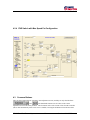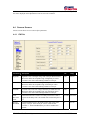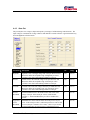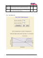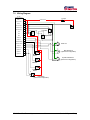
1
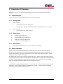
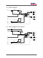
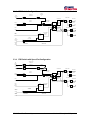
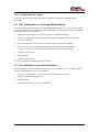
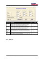
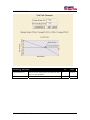
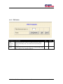
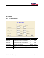
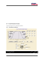
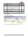
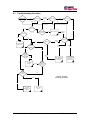
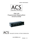
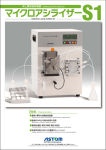
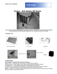
User Manual
MC200 Dual Path
Personality
Software: S0409220
Hardware: 1090548,
1090549,
1090550
Software: S0576220
Hardware: 1090824,
1090825,
1090826
Table of Contents:
1
Revision History............................................................................................ 4
2
User Manual Description .............................................................................. 5
2.1
3
Description Of Operation ............................................................................. 6
3.1
4
MC200 Controller................................................................................................. 5
Inputs/Outputs...................................................................................................... 6
3.1.1
Analog Inputs ..........................................................................................................................6
3.1.2
Digital Inputs ...........................................................................................................................6
3.1.3
Valve Output ...........................................................................................................................6
3.2
Basic Operation ................................................................................................... 6
3.3
System Block Diagrams ....................................................................................... 7
3.3.1
FNR Pot Configuration............................................................................................................7
3.3.2
FNR Pot with Max Speed Pot Configuration ..........................................................................7
3.3.3
FNR Switch Configuration......................................................................................................8
3.3.4
FNR Switch with Speed Pot Configuration.............................................................................8
3.3.5
Configuration and Tuning .......................................................................................................9
3.4
First Configuration on a Prototype Machine Model .............................................. 9
3.5
First Calibration on an Individual Machine ........................................................... 9
3.6
Calibration.......................................................................................................... 10
3.6.1
Sensors...................................................................................................................................10
3.6.2
Disconnecting Sensors...........................................................................................................10
3.6.3
Valve Calibration State Machine...........................................................................................11
WebGPI Screens ......................................................................................... 13
4.1 Table of Contents Screen and Main Run Screens for each propel command type
configuration. ............................................................................................................... 13
4.1.1
4.2
Table of contents screen ........................................................................................................13
Configuration Screen. ........................................................................................ 13
4.2.1
FNR Pot Configuration..........................................................................................................14
4.2.2
FNR Pot with Max Speed Pot Configuration. .........................................................15
4.2.3
FNR Switch Configuration. ..........................................................................................16
4.2.4
FNR Switch with Max Speed Pot Configuration. ..................................................17
4.3
Common Buttons ............................................................................................... 17
4.4
Sensors Screens................................................................................................ 18
4.4.1
FNR Pot .................................................................................................................................18
MC200 Dual Path Personality
2
Table of Contents
4.4.2
Propel Profile.........................................................................................................................19
4.4.3
Steer Pot.................................................................................................................................20
4.4.4
Steer Mode Limit...................................................................................................................21
4.4.5
Steer Profile ...........................................................................................................................22
4.4.6
Max Speed Pot.......................................................................................................................24
4.4.7
Speed Pot ...............................................................................................................................24
4.4.8
Dual Path Steer ......................................................................................................................26
4.4.9
FNR Switch ...........................................................................................................................27
4.5
Outputs .............................................................................................................. 28
4.5.1
Left Valve Parameters ...........................................................................................................28
4.5.2
Right Valve Parameters .........................................................................................................29
4.5.3
Valve Fault Parameters..........................................................................................................30
4.6
Control Parameter Screens ............................................................................... 31
4.6.1
5
6
7
State Brake AccelDecel .........................................................................................................31
Data Logging ............................................................................................... 32
5.1
Selecting the channels to log. ............................................................................ 32
5.2
The Data Logging Screen .................................................................................. 33
Troubleshooting Guide .............................................................................. 34
6.1
Troubleshooting Procedure................................................................................ 35
6.2
Fault Codes........................................................................................................ 36
6.2.1
Description of Blink Code Algorithm ...................................................................................36
6.2.2
Blink Code Translation..........................................................................................................36
System Wiring ............................................................................................. 37
7.1
Wiring Guidelines............................................................................................... 37
7.2
Wiring Diagram .................................................................................................. 39
MC200 Dual Path Personality
3
Table of Contents
1 Revision History
Version No.
Rel. Date
Changes
Name
Rev. 1.00
19Dec00
First Release
D. Dyvig
Rev 2.00
13SEP01
V2.67 WebGPI Object Library, Parse Int.,
Commas
D. Dyvig
Rev 2.01
13Dec01
Update Max current Cal
J. Wandersee
Rev 2.02
08Jan02
Update Cal routine
J. Wandersee
Rev 2.10
15Apr02
Update to PDA, latest Web Lib 2.72
J. Wandersee
Rev 2.20
10Oct02
Update to HC08A
D. Dyvig
MC200 Dual Path Personality
4
Section 1: Revision History
2 User Manual Description
This document describes how to configure and operate the MC200 Dual Path Personality. It is intended
for use by the customer, and it is maintained by Sauer-Danfoss.
The MC200 Dual Path Personality supports a PC-based service and configuration tool called WebGPI.
Reference the WebGPI user’s manual for help downloading, data logging, and performing other tasks with
WebGPI.
This User Manual does not contain hardware or electrical specifications.
2.1
MC200 Controller
MC200 Dual Path Personality
5
Section 2: User Manual Description
3 Description Of Operation
This section describes, in both text and block diagram form, how the MC200 Dual Path Personality
operates.
3.1
Inputs/Outputs
This section describes the physical characteristics of the inputs and outputs.
3.1.1
Analog Inputs
1)
Propel command
2)
•
Center Neutral, Forward, Reverse Pot
•
Max Speed pot - Will limit the maximum propel command from a value of 0 to 100%.
Steer Command
•
3.1.2
Center Neutral, Left, Right Steer Pot
Digital Inputs
1)
Calibrate Switch, High Active
2)
Neutral or Brake Switch, High Active
3)
FNR select switch input, High Active
4)
FNR select switch input, High Active
3.1.3
Valve Output
1)
Two Bi-Directional Current drivers ( 160 ma., 240 ma. Or 2.00Amp)
3.2
Basic Operation
This is an MC200 based Dual Path Personality control system. This software solution is intended to
provide the basic propel and steering control for dual path paving machines with four configurations of
Propel command input, propel pot, forward-neutral-reverse (FNR) switch and max speed pot. Another
analog input will provide the steering input.
One digital input will be used for a Neutral switch or Brake input. Absence of this signal when controller
is powered up will prevent movement of the machine. The signal must be present prior to the initial propel
command. A second digital input would be used for calibration of the valve drives. To enter calibrate
mode, the calibrate switch must be held on while powering up the system.
The MC200 has 4 proportional PWM outputs that will be used to drive two bi-directional outputs (left and
right tracks). Output current is hardware configurable up to 2 amps. Software features will include
separate acceleration and deceleration parameters.
MC200 Dual Path Personality
6
Section 3: Description Of Operation
3.3
System Block Diagrams
3.3.1
Propel
Command
ANIN_1
FNR Pot Configuration
uiSpeedPot
CmndPctX10
1
%
uiProfile
CmndPctX
10
1
Profile
Pos
FNR
uiValveCmdMa
uiLeftValveCmd
Left Forward
Y
Rate Limited
Command
ePropel
Direction
I
X
Valve
Actual Valve
Current
eLeftTrack
Direction
Acc/Dec
State
I
eRateLimited
Direction
Left Reverse
eRightTrack
Direction
Brake
uiValveCmdMa
Right Forward
Y
Digin-2
Dual Path
Open Loop
Mode
Select
uiRightValveCmd
Actual Valve
Current
uiCompensated
SteerCmd
PctX10
Steer
Limit
DIGIN-4
I
X
Valve
I
MODE
Right Reverse
uiSteer
Cmd PctX10
Steer
Command
ANIN-3
%
Pos
Steer Pot
Calibrate
Switch
eSteerDirection
Calibrate Mode
Calibrate State
DIGIN-3
3.3.2
Max
Speed
ANIN-0
Propel
Command
ANIN_1
FNR Pot with Max Speed Pot Configuration
uiMaxSpeedPot
CmndPctX10
%
Pos
Max Speed Pot
uiSpeedPot
CmndPctX10
1
%
uiProfile
CmndPctX
10
X
1
Profile
Pos
FNR
uiValveCmdMa
uiLeftValveCmd
uiLimitedPropel
CmndPctX10
Left Forward
Y
Rate Limited
Command
ePropel
Direction
I
X
Valve
Actual Valve
Current
eLeftTrack
Direction
Acc/Dec
State
I
eRateLimited
Direction
Left Reverse
eRightTrack
Direction
Brake
Dual Path
Open Loop
Mode
Select
Steer
Limit
DIGIN-4
Steer
Command
ANIN-3
Calibrate
Switch
uiValveCmdMa
Right Forward
Y
Digin-2
uiCompensated
SteerCmd
PctX10
MODE
uiRightValveCmd
X
Valve
I
Actual Valve
Current
I
Right Reverse
uiSteer
Cmd PctX10
%
Pos
Steer Pot
Calibrate Mode
eSteerDirection
Calibrate State
DIGIN-3
MC200 Dual Path Personality
7
Section 3: Description Of Operation
3.3.3
Propel
Command
ANIN_1
FNR Switch Configuration
uiSpeedPot
CmndPctX10
1
%
uiProfile
CmndPctX
10
1
Profile
Pos
Speed Pot
uiValveCmdMa
uiLeftValveCmd
Left Forward
Y
Rate Limited
Command
ePropel
Direction
DIGIN-0
DIGIN-1
F
0
1
0
1
R
0
0
1
1
D
N
F
R
N
X
Valve
Acc/Dec
State
F-N-R
I
eRateLimited
Direction
Left Reverse
eRightTrack
Direction
Brake
uiValveCmdMa
Right Forward
Y
Dual Path
Open Loop
Mode
Select
Steer
Limit
DIGIN-4
MODE
ANIN-3
Actual Valve
Current
eLeftTrack
Direction
Digin-2
Steer
Command
I
I
X
Valve
uiRightValveCmd
Actual Valve
Current
uiCompensated
SteerCmd
PctX10
I
Right Reverse
uiSteer
Cmd PctX10
%
Pos
Steer Pot
Calibrate
Switch
eSteerDirection
Calibrate Mode
Calibrate State
DIGIN-3
3.3.4
Max
Speed
ANIN-0
Propel
Command
ANIN_1
FNR Switch with Speed Pot Configuration
uiMaxSpeedPot
CmndPctX10
%
Pos
Max Speed Pot
uiSpeedPot
CmndPctX10
1
%
uiProfile
CmndPctX
10
X
1
Profile
Pos
Speed Pot
DIGIN-1
F R D
0 0 N
1 0 F
0 1 R
1 1 N
Rate Limited
Command
Acc/Dec
State
F-N-R
I
Left Reverse
eRightTrack
Direction
uiValveCmdMa
Right Forward
Y
Dual Path
Open Loop
Mode
Select
Steer
Limit
DIGIN-4
Calibrate
Switch
Actual Valve
Current
eRateLimited
Direction
Brake
ANIN-3
I
X
Valve
eLeftTrack
Direction
Digin-2
Steer
Command
Left Forward
Y
ePropel
Direction
DIGIN-0
uiValveCmdMa
uiLeftValveCmd
uiLimitedPropel
CmndPctX10
uiCompensated
SteerCmd
PctX10
MODE
uiRightValveCmd
X
Valve
I
Actual Valve
Current
I
Right Reverse
uiSteer
Cmd PctX10
%
Pos
Steer Pot
eSteerDirection
Calibrate Mode
Calibrate State
DIGIN-3
MC200 Dual Path Personality
8
Section 3: Description Of Operation
3.3.5
Configuration and Tuning
This section describes what needs to be configured and how to configure the MC200 Dual Path
Personality.
3.4
First Configuration on a Prototype Machine Model
This section describes how to configure the MC200 Dual Path Personality a for specific machine model.
The configurations can be saved and made into the default file for a specific machine model. WebGPI is
required to perform most of the actions.
1.
Apply power to the MC200. It is not necessary to have the machine running yet.
2.
Choose the Configuration screen and choose the appropriate configuration for your application.
3.
Re-power the MC200.
4.
Choose the dual path screen to set the Pivot(counter rotate) point and pivot deadband.
5.
Choose the accel/decel screen to change the acceleration and deceleration of the machine.
6.
Choose Steer Limit screen and set the maximum steer percent allowed for each mode.
7.
Calibrate any sensors used.
8.
Start the machine.
9.
Calibrate the Valve Drivers .
10. Drive the machine and make adjustments as needed.
3.5
First Calibration on an Individual Machine
Once the defaults have been established from the previous section, there are only a few steps to calibrate
the MC200 Dual Path Personality for each machine.
1.
Apply power to the MC200. It is not necessary to have the machine running yet.
2.
Calibrate the FNR Pot and the Steer Pot.
3.
Start the machine.
4.
Calibrate the Valve Drivers. See section 3.6.3.1.
MC200 Dual Path Personality
9
Section 3: Description Of Operation
3.6
Calibration
See section 3.6.3.1. Threshold and Max- Current/Steer-Tracking Calibration
3.6.1
Sensors
3.6.1.1 Three Position Sensors
The three position sensors are:
•
Steer Pot
•
Propel FNR Pot
To calibrate a three position sensor, the following three actions must be performed in any order:
•
Hold the sensor in the neutral position for at least three seconds.
•
Hold the sensor in the maximum position for at least three seconds.
•
Hold the sensor in the minimum position for at least three seconds.
3.6.2
Disconnecting Sensors
If a sensor is disconnected while the power is still on, a fault is indicated by the red Status LED (See Fault
Codes in section 6.2). In addition, the calibration points are set to zero and the calibration state is changed
to uncalibrated. When the sensor is reconnected, the calibration procedure needs to be repeated in order to
put the sensor back into the calibrated state.
MC200 Dual Path Personality
10
Section 3: Description Of Operation
MC200 Dual Path Personality
11
Steer Command > Pivot%
Steer Command <= Pivot%
Calib121
WAIT
Propel = Neutral
Calib12 (Threshold Calibration)
Set thresholds = 0
Set Max Current = 120% Max
Forward and Reverse Valve
Current.
All Pots = kNoError
WAIT
Send Calibrate Switch
pulse to valve objects
Calibrate Switch Pressed
Set Propel % to threshold
value for forward and
reverse right steer and
forward and reverse Left
steer
YES
Calibrate Switch = ON?
Calib122
One or more Pot errors
Calibrate switch = OFF
Check for Pot Calibration
Calib11
Calib1State
DualPathStateMachine.vsd
Dan Dyvig
11Jan01
Dual Path Personality
State Machine
State0
ReverseCal =
FALSE
ForwardCal =
FALSE
Calibrate Switch Pressed
Calibrate Switch Pressed
Set ForwardCal =
TRUE
Save Calibrate
Values
Calibration Fault
Drive Machine
Calib131
Drive Reverse
Calib133
Run22State
Application Active
ReverseCal = TRUE
ForwardCal = TRUE
Drive Forward
Calib132
Forward Command > 0
Reverse Command > 0
Calib13
On Fault
Propel direction = Neutral
Save to E 2
Calib15
Set all Pot outputs to 0
Start
Run21State
All thresholds calibrated
Steer Direction = Neutral
Subtract threshold delta to
balance max current span.
NO
Run2State
Set ReverseCal =
TRUE
Save Calibrate
Values
3.6.3
Valve Calibration State Machine
Section 3: Description Of Operation
Fig 1. State Diagram
3.6.3.1 Threshold and Max- Current/Steer-Tracking Calibration
Calibrating the Valve Drivers sets their threshold values, maximum current for each side and straight steer
correction. The threshold values are the minimum current outputs for the Valve Drivers that are just under
the current required for the track to start moving. Before starting the calibrate procedure there are a few set
up actions to do. These steps are as follows:
A. Set the nominal resistance value for the coils in use on the Valve fault set up screens.
B. When you enter calibrate mode, the maximum current values for each valve are set to the
system default values. These values will be increased by 20% during the calibrate procedure to
ensure that the valves are saturated with full propel command. These values will be optimized
during the calibrate procedure
C. The Configuration Screen will display the Maximum Current Available for each controller.
D.
Refer to figure 1 on the previous page and calibrate by performing the steps below in the
order given :
1) Set the propel command Pot at neutral position.
2) Set steering wheel to full CW position.
3) Turn power to the controller OFF.
4) Turn or press the calibrate switch to ON and hold in position.
5) Turn machine power ON. Machine goes to Calib 1 State - Wait
6) Release(Turn off) Calibrate switch. Machine goes to Calib 1 State – Calib 11
7) If there are no pot faults, enter state Calib 12 - Calib122, all thresholds are set to zero,
and max current is set to max available current.
8) Set the FNR switch to Forward and slowly increase the speed pot or, depending on
configuration, slowly move the FNR propel pot to the forward position until the left track
just begins to move, back off until the track just stops. This is the threshold current. Press
and release the calibrate button then return the propel handle to neutral. Move FNR propel
handle to the reverse position and wait until the left track just begins to move, press and
release the calibrate button then return the propel handle to neutral. This completes the
threshold calibration for one side.
9) Repeat steps 7 and 8 with the steer pot in the full CCW position
The next procedure will calibrate the maximum current for each track so that the vehicle tracks in a straight
line when steering straight ahead or neutral steer position. This procedure requires that the machine have
ample space to run in a straight line forward and backward for at least 30 seconds. Calibrate by
performing the steps below in the order given:
1) Set the steer pot to the straight-ahead or neutral position. This will put the controller in the
calib131 State.
2) Move the propel control handle to the full forward position then slowly move the handle back
toward neutral until a speed change is detected. Try to find the point where increased handle
command does not increase speed. Then steer the machine until it maintains a straight ahead
direction. When this condition is met, press and release the calibrate button then return the propel
handle to neutral. Repeat steps 1 and 2 for the reverse direction.
MC200 Dual Path Personality
12
Section 3: Description Of Operation
3) When both sides are calibrated, the controller will save the new calibrated values in state Calib15
and then return to normal operation in the Run22 state after the propel is returned to neutral.
4 WebGPI Screens
This section explains all screens specific to the MC200 Dual Path Personality. For help with general
WebGPI screens, see the WebGPI User Manual.
4.1
4.1.1
Table of Contents Screen and Main Run Screens for each propel
command type configuration.
Table of contents screen
Clicking on an item beneath Sensors or Control Parameter opens the corresponding adjustment screen.
Main opens the main run screen.
Help disabled disables or enables the help display messages.
Disconnect disconnects the computer from the MC200 controller.
4.2
Configuration Screen.
Parameter
Description
Unit
Range
Propel Input Type
Select
Select 1 of 4 possible choices. These choices are
shown in the following four paragraphs
PWM (Hz)
Selects the frequency that the valve outputs will run
at.
Hz
80 to 200
Max Available
Current.
This is the maximum current capability of this
hardware
mA
166 to
2000
MC200 Dual Path Personality
13
1 of 4
Section 4: WebGPI Screens
4.2.1
FNR Pot Configuration.
MC200 Dual Path Personality
14
Section 4: WebGPI Screens
4.2.2 FNR Pot with Max Speed Pot Configuration.
MC200 Dual Path Personality
15
Section 4: WebGPI Screens
4.2.3 FNR Switch Configuration.
MC200 Dual Path Personality
16
Section 4: WebGPI Screens
4.2.4 FNR Switch with Max Speed Pot Configuration.
4.3
Common Buttons
There are three buttons that are common to most adjustment screens, and they are only described here:
,
, and
. The SetDefaults button resets all values in the current
adjustment screen to the factory defaults. The Get button retrieves the current values from the controller
(this is done automatically when a new screen is loaded). Pressing the Send button first initiates a data
MC200 Dual Path Personality
17
Section 4: WebGPI Screens
validation check, which will stop the transmission of non-conforming data. Then, if the validation passes,
the values displayed on the adjustment screen are sent to the controller.
4.4
Sensors Screens
Sensors screens allow access to sensor object parameters.
4.4.1
FNR Pot
Parameter
Description
Unit
Range
HighSide
HighSide refers to the high voltage end of the pot. MinValue and
MaxValue define the acceptable range of HighSide pot values.
CalValue is the value learned during calibration of the pot.
Volts
0.0-5.0
Neutral
Neutral refers to the centered voltage of the pot. MinValue and
MaxValue define the acceptable range of Neutral pot values.
CalValue is the value learned during calibration of the pot.
Volts
0.0-5.0
LowSide
LowSide refers to the low voltage end of the pot. MinValue and
MaxValue define the acceptable range of LowSide pot values.
CalValue is the value learned during calibration of the pot.
Volts
0.0-5.0
Fault
Detection
Time
Fault Detection Time is used to set a delay time before a fault is
registered. The delay time is in Seconds with one decimal place i.e:
1.3
Seconds
0.0-100.0
Neutral
Deadband
NeutralDeadband refers to the band on either side of the center
voltage of the pot. If the actual pot value is within Neutral
CalValue +/- Neutral Deadband, the pot will be considered in
Neutral.
%
0 to 30
MC200 Dual Path Personality
18
Section 4: WebGPI Screens
Upper and
Lower
Deadband
Deadband refers to the band on either end of the pot in % of pot
travel. If the actual pot value is within the specified % value of full
pot travel, the pot is treated as if it at 100%. This is to prevent the
pot from falling short of 100% because of sight changes in pot
travel.
Status:
Possible status values are: OK, Value at 5V, Value too High, Value
at 0V, Value too Low, and Not Calibrated.
4.4.2
%
0 to 30
Unit
Range
Propel Profile
Parameter
Description
Min Value
The minimum value accepted on input and minimum value to
the output
%x10
0-1000
Knee Value
This is the point at which the slope of the profile changes
%x10
0-1000
Max value
The maximum value accepted on input and maximum value to
the output
%x10
0-1000
MC200 Dual Path Personality
19
Section 4: WebGPI Screens
4.4.3
Steer Pot
The pot3obj takes in a voltage as input and outputs a percentage of calibrated range and a direction. The
input voltage is considered out of range when less than half the LowSide CalValue or greater than half way
between HighSide CalValue and 5V.
Parameter
Description
Unit
Range
HighSide
HighSide refers to the high voltage end of the pot. MinValue and
MaxValue define the acceptable range of HighSide pot values.
CalValue is the value learned during calibration of the pot.
Volts
0.0-5.0
Neutral
Neutral refers to the centered voltage of the pot. MinValue and
MaxValue define the acceptable range of Neutral pot values.
CalValue is the value learned during calibration of the pot.
Volts
0.0-5.0
LowSide
LowSide refers to the low voltage end of the pot. MinValue and
MaxValue define the acceptable range of LowSide pot values.
CalValue is the value learned during calibration of the pot.
Volts
0.0-5.0
Neutral
Deadband
NeutralDeadband refers to the band on either side of the center
voltage of the pot. If the actual pot value is within Neutral
CalValue +/- Neutral Deadband, the pot will be considered in
Neutral.
%
0 to 30
Upper and
Lower
Deadband
Deadband refers to the band on either end of the pot in % of pot
travel. If the actual pot value is within the specified % value of full
pot travel, the pot is treated as if it at 100%. This is to prevent the
pot from falling short of 100% because of sight changes in pot
%
0 to 30
MC200 Dual Path Personality
20
Section 4: WebGPI Screens
travel.
Fault
Detection
Time
Fault Detection Time is used to set a delay time before a fault is
registered. The delay time is in Seconds with one decimal place i.e:
1.3
Status:
Possible status values are: OK, Value at 5V, Value too High, Value
at 0V, Value too Low, and Not Calibrated.
4.4.4
Seconds
0.0-100.0
Steer Mode Limit
MC200 Dual Path Personality
21
Section 4: WebGPI Screens
Parameter
Description
Unit
Range
Mode 0 Steer (%)
Limits the output from the steer pot in mode 0 to
Mode 0 steer percent. 100% means 0 – 100% steer
command allowed.
%
0-100.0
Mode 0 Steer (%)
Limits the output from the steer pot in mode 1 to
Mode 1 steer percent. 100% means 0 – 100% steer
command allowed.
%
0-100.0
4.4.5
Steer Profile
MC200 Dual Path Personality
22
Section 4: WebGPI Screens
Parameter
Description
Unit
Range
Min Value
The minimum value accepted on input and minimum value to
the output
%x10
0-1000
Knee Value
This is the point at which the slope of the profile changes
%x10
0-1000
Max value
The maximum value accepted on input and maximum value to
the output
%x10
0-1000
MC200 Dual Path Personality
23
Section 0:
4.4.6
Max Speed Pot
Parameter
Description
Unit
Range
HighSide
HighSide refers to the high voltage end of the pot. MinValue and
MaxValue define the acceptable range of HighSide pot values.
CalValue is the value learned during calibration of the pot.
Volts
4.2-4.8
LowSide
LowSide refers to the low voltage end of the pot. MinValue and
MaxValue define the acceptable range of LowSide pot values.
CalValue is the value learned during calibration of the pot.
Volts
0.2-5.0
Fault
Detection
Time
Fault Detection Time is used to set a delay time before a fault is
registered. The delay time is in Seconds with one decimal place i.e:
1.3
Seconds
0.0-100.0
Status:
Possible status values are: OK, Value at 5V, Value too High, Value
at 0V, Value too Low, and Not Calibrated.
4.4.7
Speed Pot
MC200 Dual Path Personality
24
Section 0:
Parameter
Description
Unit
Range
HighSide
HighSide refers to the high voltage end of the pot. MinValue and
MaxValue define the acceptable range of HighSide pot values.
CalValue is the value learned during calibration of the pot.
Volts
4.2-4.8
LowSide
LowSide refers to the low voltage end of the pot. MinValue and
MaxValue define the acceptable range of LowSide pot values.
CalValue is the value learned during calibration of the pot.
Volts
0.2-5.0
Fault
Detection
Time
Fault Detection Time is used to set a delay time before a fault is
registered. The delay time is in Seconds with one decimal place i.e:
1.3
Seconds
0.0-100.0
Status:
Possible status values are: OK, Value at 5V, Value too High, Value
at 0V, Value too Low, and Not Calibrated.
MC200 Dual Path Personality
25
Section 0:
4.4.8
Dual Path Steer
Parameter
Description
Unit
Range
Counter Rotate (%)
Percent of steer wheel position from center to reach
the pivot steer deadband
%
0-100.0
Pivot Deadband (%)
Amount of deadband around the pivot point
%
0-100.0
MC200 Dual Path Personality
26
Section 0:
4.4.9
FNR Switch
Parameter
Description
Unit
Range
Fault
detection
time (s)
Fault Detection Time is used to set a delay time before a fault is
registered. The delay time is in Seconds with one decimal place
e.g.: 1.3
Seconds
0.0-10.0
Status:
Possible status values are: OK, Value at 5V, Value too High, Value
at 0V, Value too Low, and Not Calibrated.
MC200 Dual Path Personality
27
Section 0:
4.5
4.5.1
Outputs
Left Valve Parameters
Parameter
Description
Unit
Range
X Input Min.
Minimum expected value of the command input to
this module.
%
0-100
X Input Max.
Maximum expected value of the command input to
this module
%
0-100
Y Output Max
Output value at Max. Input value.
Milliamps
0-2500
Thresholds
Minimum value of current to just put the pump into
stroke.
Milliamps
Status
Possible status values are: O.K. or not calibrated
MC200 Dual Path Personality
28
Section 0:
4.5.2
Right Valve Parameters
Parameter
Description
Unit
Range
X Input Min.
Minimum expected value of the command input to
this module.
%
0-100
X Input Max.
Maximum expected value of the command input to
this module
%
0-100
Y Output Max
Output value at Max. Input value.
Milliamps
0-2500
Thresholds
Minimum value of current to just put the pump into
stroke.
Milliamps
Status
Possible status values are: O.K. or not calibrated
MC200 Dual Path Personality
29
Section 0:
4.5.3
Valve Fault Parameters
Parameter
Description
Unit
Range
Fault Detection Time
(s)
Time delay before fault is reported
Sec
0.1 –10.0
Coil Resistance
(ohms)
Nominal resistance value of the Control coil
Ohms
1-60
Status
Possible status values are: O.K. , Forward or Reverse
coil Short or Open
MC200 Dual Path Personality
30
Section 0:
4.6
Control Parameter Screens
Control screens allow access to control object parameters.
4.6.1
State Brake AccelDecel
Parameter
Description
MC200 Dual Path Personality
Unit
31
Range
Section 0:
T1 Up (ms)
Final non-linear up ramp
Ms
0 - 1000
TR Up (ms)
Acceleration ramp up time.
Ms
0 - 10000
TR1 UP (ms)
Initial non-linear up ramp
Coasting
These are the deceleration values used for each of these
conditions, Coasting means handle toward but not at neutral.
Neutral means handle from some value to neutral. Direction
change means when moving the handle from forward to
reverse or vice versa without stopping at neutral. Brake is
when the Enable Propel signal is removed
Ms
0-10000
Ms
0-10000
Neutral
Dir Change
Brake
TR1 Down
TR1 Up is the ramp up time in ms for an input of 1000. An
input of 500 would ramp up in half the specified time.
TR Down
Deceleration ramp down time.
T1 Down
T1 Down is the ramp down time in ms for an input of 1000.
An input of 500 would ramp down in half the specified time.
5 Data Logging
5.1
Selecting the channels to log.
Select the Data Logging function
to see the data logging screen.
Click on a data box and the box will be highlighted. These data will be displayed on the graph on the data
logging screen. Select as many data channels as you need for your analysis.
MC200 Dual Path Personality
32
Section 5: Data Logging
5.2
The Data Logging Screen
MC200 Dual Path Personality
33
Section 5: Data Logging
6
Troubleshooting Guide
This section outlines a strategy that can be used to solve problems in the control system. A common
technique used in problem-solving is exchanging components. However, a very important element
necessary to the timely and successful conclusion of this activity is the correct selection of the
malfunctioning component. A thorough understanding of the entire system and an elimination process
leading to the malfunctioning component is absolutely necessary before starting the exchange activity.
Reduce the random exchange of components by carefully analyzing the symptoms and then conducting
tests to determine which of the elements in the system is likely to be the problem. The technician should
use the flow chart below as a guide to locate the problem.
Since it is new, the electronic controller is often the first component targeted for exchange. However, the
malfunction of an electronic controller is extremely rare and, therefore, it should be the last component
considered for replacement. In fact, the electronic controller has an internal ability to diagnose itself and
the connections attached to it. This information can be very helpful in finding the problem area. If the
electronic controller is responding to commands and not giving diagnostics that indicate an internal
problem, the likelihood that the problem is internal to the electronic controller is remote.
MC200 Dual Path Personality
34
Section 6: Troubleshooting Guide
6.1
Troubleshooting Procedure
System function
No
All other
Controllers
Controller Type
DC2, S2X
Power Led
Off
On
System Led
Off
Abnormal
On
Power Led
Off
On
Check Power
to Controller
OK
Replace Controller
Status Led
Solid Off or
Solid On
ON
Off
Mode Led
Off
See description of
display codes
Status Led
Spare
controller
available?
Yes
Blinking
0.5 Hz
Blinking
Code
Blinking
10Hz
No
Check all
external
switches w/
Spare
controller
Blinking
Code
Fix external
switches
OK
See description of
blink algorithm in
next section
Not OK
Not OK
Check
hydraulic
system
No application
loaded. Download
application or
replace controller.
Check all
external
switches w/
voltmeter
OK
Generic Trouble
Shooting procedure
Not OK
OK
Need to Connect
to PC with
WebGPI for online
diagnostic
MC200 Dual Path Personality
Fix hydraulic
system
35
Section 6: Troubleshooting Guide
6.2
Fault Codes
When the controller detects a fault condition, it signals the specific fault using the red Status LED. Under
normal conditions with no error present, the red LED is off and the yellow LED blinks at a 0.5 Hz rate. If
no application code is loaded in the controller, the red LED is off and the yellow LED blinks at a 10 Hz
rate. All other errors (those specific to the application) are decoded by observing “blink codes” generated
by the red LED.
Yellow LED (Mode)
Red LED (Status)
System Status:
10 Hz blink rate
Off
No application loaded
0.5 Hz blink rate
Off
Application loaded and no error
0.5 Hz blink rate
4 bit blink code to describe fault
Application loaded and error
6.2.1
Description of Blink Code Algorithm
If the yellow LED blinks at an unvarying 0.5 Hz rate and the red LED is blinking, the cause of the fault can
be decoded from the red LED alone as follows: the red LED will flash a four bit sequence, followed by a
pause, followed by the four bit sequence, the pause, and so on. The long flash, symbolized by a “-”, lasts
approximately one second. The short flash, symbolized by a “•”, lasts approximately one-half second.
The pause between the four bit sequence lasts approximately 3.5 seconds. If more than one fault exists,
each fault will be displayed in sequence before being repeated.
6.2.2
Blink Code Translation
Fault
Flash Bit
Device at Fault
Cause of Fault
Machine Response
Code
Sequence
1
−•••
Speed pot, unidirectional
command Input
Voltage signal is out of
range or input is
uncalibrated.
No output from the speed
pot will cause machine to
stop.
2
•−••
Max speed pot, unidirectional
command Input
Voltage signal is out of
range or input is
uncalibrated.
No output from the max
speed pot. Machine will
stop.
3
−−••
FNR pot Bi-directional
command input
Voltage signal is out of
range or input is
uncalibrated.
FNR command will return to
neutral and machine will
stop.
4
••−•
Steer pot Bi-directional
command input
Voltage signal is out of
range or input is
uncalibrated.
Machine will steer straight.
at any handle setting.
5
−•−•
FNR Object
RPM below 200, or no RPM
at all.
Machine will revert to
neutral causing the machine
to stop.
7
−−−•
Left Valve
Uncalibrated.
Machine will revert to
neutral causing the machine
to stop.
MC200 Dual Path Personality
36
Section 6: Troubleshooting Guide
Fault
Flash Bit
Code
Sequence
Device at Fault
Cause of Fault
Machine Response
8
•••−
Right Valve
Uncalibrated.
Machine will revert to
neutral causing the machine
to stop.
9
−••−
Right Valve Forward Coil
Open or Short.
Machine will revert to
neutral causing the machine
to stop.
10
•−•−
Right Valve Reverse Coil
Open or Short.
Machine will revert to
neutral causing the machine
to stop.
11
−−•−
Left Valve Forward Coil
Open or Short.
Machine will revert to
neutral causing the machine
to stop.
12
••−−
Left Valve Reverse Coil
Open or Short.
Machine will revert to
neutral causing the machine
to stop.
“•” = short flash = 0
“−” = long flash = 1
7 System Wiring
7.1
Wiring Guidelines
1.
Protect all wires from mechanical abuse. Wire can be run in flexible metal or plastic conduits.
2.
Use 85°C wire with abrasion resistant insulation. 105°C wire should be considered near hot
surfaces.
3.
Use #18 gauge wire or greater. #14 or #16 wire is preferred.
4.
Separate high current wires such as solenoids, lights, alternators, or fuel pumps from control
wires.
5.
Run wires along the inside of, or close to, metal machine frame surfaces where possible. This
simulates a shield, which will minimize the effects of EMI/RFI radiation.
6.
Do not run the wires near sharp metal corners. Consider running the wire through a grommet
when rounding a corner.
7.
Do not run wires near hot machine members.
MC200 Dual Path Personality
37
Section 7: System Wiring
8.
Provide strain relief for all wires.
9.
Avoid running wires near moving or vibrating components.
10.
Avoid long, unsupported wire spans.
11.
Twist all sensor lines. (About one turn every 4 inches or 10 cm.)
12.
Use harness anchors which will allow wires to “float” with respect to the machine frame rather
than rigid anchors.
MC200 Dual Path Personality
38
Section 7: System Wiring
7.2
Wiring Diagram
MC 200
Packard Connector
5 Amps
Battery +
A1
Sensor Power
A2
Battery -
A3
Valve Drive (0+)
B1
Valve Drive (0-)
B2
Valve Drive (1+)
B3
Switched Power
Battery
12/24V
Left EDC
TxD
C1
A
B
RxD
C2
C
Boot
C3
Analog In 0
D1
D3
AIN4/PPU1/DIN4
E1
Analog In 2
E2
Valve Drive (1-)
E3
Digital In 0
F1
Digital In 1
F2
Digital In 2
F3
D
B
C
B
C
Right EDC
125
Steer Pot
125
125
1K
D2
A
D
1K
Analog In 1
AIN3/PPU0/DIN3
3 Pin
Weather
Pack
A
Max Speed Pot
(optional via configuration)
125
Mode
Select
125
1K
Speed Pot/FNR Pot
(optional via configuration)
125
Calibrate
G
F
Parking
Brake
N
R
MC200 Dual Path Personality
FNR Switch
(optional via configuration)
39
Section 7: System Wiring
Sauer-Danfoss Hydraulic Power Systems
- Market Leaders Worldwide
OUR PRODUCTS
Sauer-Danfoss is a comprehensive supplier providing
complete systems to the global mobile market.
Hydrostatic transmissions
Sauer-Danfoss serves markets such as agriculture,
construction, road building, material handling, municipal,
forestry, turf care, and many others.
Hydraulic power steering
Electric power steering
We offer our customers optimum solutions for their
needs and develop new products and systems in close
cooperation and partnership with them.
Closed and open circuit axial piston
pumps and motors
Sauer-Danfoss specializes in integrating a full range of
system components to provide vehicle designers with
the most advanced total system design.
Gear pumps and motors
Sauer-Danfoss provides comprehensive worldwide
service for its products through an extensive network of
Authorized Service Centers strategically located in all
parts of the world.
Bent axis motors
Radial piston motors
Orbital motors
Transit mixer drives
Planetary compact gears
Proportional valves
Directional spool valves
Cartridge valves
Sauer-Danfoss (EH-US) Company
3500 Annapolis Ln. N.
Minneapolis, MN 55447, USA
Phone: + 1 763 509-2102, Fax: +1 763 599-5769
Sauer-Danfoss (US) Company
2800 East 13th Street
Ames, IA 50010, USA
Phone: + 1 515 239-6000, Fax: +1 515 239 6618
Sauer-Danfoss (Neumünster) GmbH & Co. OHG
Postfach 2460, D-24531 Neumünster
Krokamp 35, D-24539 Neumünster, Germany
Phone: +49 4321 871-0, Fax: +49 4321 871 284
Sauer-Danfoss (Nordborg) A/S
DK-6430 Nordborg, Denmark
Phone: +45 7488 4444, Fax: +45 7488 4400
Hydraulic integrated circuits
Hydrostatic transaxles
www.sauer-danfoss.com
Integrated systems
MC200 Dual Path Personality
40
Section 7: System Wiring