1
DLV1280 DX User's Manual
Table of Contents
Section
1
Introduction
2
Installation &
Setup
3
Operation
4
Maintenance
5
6
Specifications
Appendices
Contents
Page
1.1
1.2
1.3
The Projector ....................................................................................................1-1
Components ......................................................................................................1-2
Purchase Record and Servicing.........................................................................1-2
2.1
2.2
2.3
2.4
2.5
2.6
2.7
2.8
2.9
2.10
Quick Setup.......................................................................................................2-1
Installation Considerations................................................................................2-2
Projector Position and Mounting ......................................................................2-7
Source Connections ........................................................................................2-12
Power Connection...........................................................................................2-19
Operating Orientation .....................................................................................2-19
Leveling ..........................................................................................................2-20
Zoom, Focus & Lens Offset ............................................................................2-20
Serial Port Connections...................................................................................2-20
Keypad Protocols and Conversion ..................................................................2-27
3.1
3.2
3.3
3.4
3.5
3.6
3.7
3.8
3.9
3.10
3.11
Overview...........................................................................................................3-1
Projector Basics ................................................................................................3-1
Using the Keypad..............................................................................................3-3
Navigating the Menus .....................................................................................3-11
Using Inputs and Channels..............................................................................3-15
Adjusting the Image ........................................................................................3-21
Configuring System Parameters ......................................................................3-37
Working With the Lamp .................................................................................3-44
Projector Status...............................................................................................3-47
Using Multiple Projectors ...............................................................................3-47
Error Conditions .............................................................................................3-59
4.1
4.2
4.3
4.4
4.5
4.6
Warnings and Guidelines ..................................................................................4-1
Cleaning ............................................................................................................4-3
Replacing Keypad Batteries..............................................................................4-3
Replacing the Lamp and Filter ..........................................................................4-4
Replacing the Lens............................................................................................4-8
Troubleshooting ..............................................................................................4-11
5.1
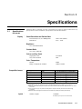
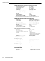
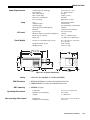
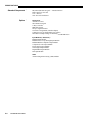
Specifications....................................................................................................5-1
A
B
C
D
E
F
Glossary ...........................................................................................................A-1
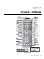
Keypad Reference............................................................................................ B-1
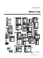
Menu Tree........................................................................................................ C-1
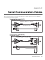
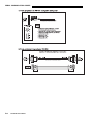
Serial Communication Cables ..........................................................................D-1
Throw Distance................................................................................................ E-1
Optional Input Modules ................................................................................... F-1
NOTE: Due to continuing research, all information in this manual is subject to change without notice
54-017137-06P Software Version 2.1 (10/02)
DLV1280 DX User’s Manual
iii
Section 1
Introduction
1.1
The Projector
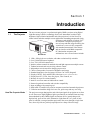
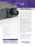
The DLV1280 DX projector is a professional quality DMD projector using Digital
Light Processing (DLP) technology from Texas Instruments to achieve highbrightness, high resolution multimedia and video projection. It is ideal for use in
control rooms and other multiple-screen applications demanding unsurpassed clarity,
consistency and reliability in critical “24/7”
environments. Designed specifically for
ease-of-setup and total image flexibility, the
versatile DLV1280 DX is fully compatible
with standard international video formats
and can interface with IBM-compatible
PC, Macintosh computers and
workstations. DLV1280 DX features include:
DLV1280 DX
◊
◊
◊
◊
◊
◊
◊
◊
◊
◊
◊
◊
◊
◊
◊
◊
1280 x 1024 pixels true resolution, with other resolutions fully scaleable
Over 1500 ANSI lumens brightness
Over 750:1 full-field contrast ratio
Intuitive software controls for matched color and light output across multiple screens
Tandem horizontal and vertical sizing software control
Independent vertical stretch for changing aspect ratios
Choice of lamp modes for control of brightness and energy
Standard short-throw lens for image sizes from 5 to 30 feet (diagonal)
Display of NTSC, PAL and SECAM video input (requires optional decoder)
Display from PCs, VCRs, laser disc players, video cameras, etc.
Memory for up to 99 custom channels
Intuitive on-screen menus or hidden direct control
Remote keypad and controller and switcher compatibility
Input switching with remote keypad
Built-in RS-232 and RS-422 ports for computer control and networked projectors
Utilitarian and modular design for lower cost, quick setup and easy servicing.
How The Projector Works ' The projector accepts data/graphics and video input signals for projection on to front
or rear flat screens. High brightness light is generated by an internal Xenon arc lamp,
then modulated by three DMD (digital micromirror device) panels that provide
digitized red, green or blue color information. Light from the “on” pixels of each
panel is reflected, converged and then projected to the screen through a single front
lens, where all pixels are perfectly superimposed as a sharp full-color image.
DLV1280 DX User’s Manual
1-1
INTRODUCTION
1.2
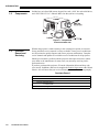
Components
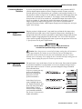
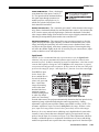
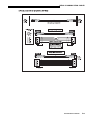
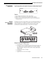
Included are an infrared (IR) remote keypad, line cord, a 9/64” hex socket ball driver,
and a DLV1280 DX User’s Manual. Make sure that you have everything.
Figure 1.1. Components
SHOWN WITH ADDED LENS
1.3
Purchase
Record and
Servicing
Whether the projector is under warranty or the warranty has expired, an extensive
factory and dealer service network is always available. Factory service technicians
are fully trained to quickly diagnose and correct projector malfunctions. Complete
service manuals and updates are available to service technicians for all projectors.
Should you encounter a problem with the projector and require assistance, contact
your dealer or the manufacturer. In many cases, any necessary servicing can be
performed on site.
If you have purchased the projector, fill out the information below and keep with
your records. In addition, make sure to complete the Product Registration at the Christie
website—this will ensure that you receive all future product communications promptly.
Purchase Record
Dealer:
Dealer Phone Number:
Projector Serial Number*:
Purchase Date:
Installation Date, if applicable:
* NOTE: The projector serial number is located on the projector's rear identification label
1-2
DLV1280 DX User’s Manual
Section 2
Installation & Setup
This section explains how to install and set up the projector. If you are familiar with the projector and want to quickly
set it up for temporary use, follow the Quick Setup instructions below. For a more complete setup, follow the
instructions and guides covered in the remaining subsections.
NOTES: 1) The lens is not mounted when the projector is shipped from the factory. For instructions on how to install
or replace a lens, refer to 4.5, Replacing the Lens. 2) This manual assumes the optional decoder is installed.
2.1
Quick Setup
Follow these steps for quick setup of the projector in a standard floor mount position.
STEP 1 ' Position the Projector
Set the projector at the expected throw distance (projector-to-screen distance) and
center the lens with the screen. See 2.3, Projector Position and Mounting and
Appendix E. Refer also to the dimensioned diagrams of the projector provided in
Section 5. Make sure that the projector is level from side-to-side (see 2.7, Leveling),
adjusting feet if necessary.
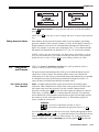
STEP 2 ' Connect a Source
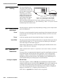
Locate the main input panel at the rear of the projector. The lower left area, labeled
INPUT 1, accepts an RGB input via BNC connectors. The upper right area (assuming
an optional video decoder is installed) accepts a composite video at INPUT 3 or Svideo input at INPUT 4. Connect your source to the appropriate panel connectors.
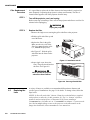
STEP 3 ' Connect the Line Cord to AC Power
Connect the projector’s line cord to the AC receptacle at the lower right rear corner of the
projector and to proper AC. Input power required is 100 - 240 VAC, 50 to 60 Hz @ 9 amps
(@ 100 V). Use the line cord provided with the projector. See Section 5.
WARNING
Do not attempt operation if the AC supply and cord are not
within the specified voltage and power range. See Section 5.
STEP 4 ' Turn the Projector ON
Using the remote keypad, press Power* and hold for approximately 1 second to turn the
projector on (or press Power* ON ). Let the projector warm up for about five minutes.
The POWER LED, located in the lower right corner of the rear input panel, should
glow a steady green.
DLV1280 DX User’s Manual
2-1
INSTALLATION AND SETUP
STEP 5 ' Select a Source
Using the remote keypad, press Input1 , Input2 , Input3 , or Input4 to select and display the
image for the source you connected in Step 2. The display will resize as needed,
producing an image as large as possible for the type of source present.
STEP 6 ' Adjust Image
• ZOOM: With the input image displayed, rotate the textured ring on the lens
barrel to increase or decrease the image size (this requires a zoom lens). If you
don’t have a zoom lens or you can’t adjust the image enough, the projector
may not be positioned properly for your screen size. Power down, unplug the
projector and move the projector in relation to the screen. See 2.3, Projector
Position and Mounting for details.
• FOCUS: At the lens opening, turn the focus tab to sharpen the image as well as
possible.
• OFFSETS: If the lens is centered with the screen but you still find it necessary
to shift the image, you can do so by slightly repositioning the lens mount
within the projector. See 2.3, Projector Position and Mounting (note: qualified
service technician required).
• OTHER: Press Menu to refine other display parameters as described in Section 3.
2.2
Installation
Considerations
Although the DLV1280 DX delivers a high brightness, high resolution output, final
display quality could be compromised if the projector is improperly installed. This
subsection discusses issues you should consider before proceeding with a final
installation. Even if you do not intend to use the projectors in a fixed and permanent
installation, this subsection will help you to better understand what you can do to
enhance display performance.
Lifting or Hoisting
For any new installation, you may have to safely lift or hoist the projector into place.
Securely wrap hoisting cabling and safety straps around the whole projector. Attach
to the proper Christie ceiling mount only—never suspend or “fly” this model.
WARNINGS
Never stack projectors. The top projector could slide off
and cause injury or death. Never “fly” this model.
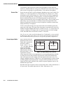
Installation Type ' Choose the installation type which suits your needs: front or rear screen, floor mount
or inverted mount.
Front Screen, Floor Mount Installation
ADVANTAGES
•
•
•
Easy to set up
Can be moved or changed quickly
Easy to access
CONSIDERATIONS
•
Shares floor space with audience
Front Screen, Inverted Mount (ceiling) Installation
ADVANTAGES
•
•
•
2-2
DLV1280 DX User’s Manual
Does not take up audience space
Projector is unobtrusive
Projector cannot be accidentally moved
CONSIDERATIONS
•
•
Installation is more permanent
It is more difficult to access the projector
INSTALLATION & SETUP
Rear Screen, Floor Mount Installation
ADVANTAGES
•
•
•
Projector is completely hidden
Projector is easily accessed
Usually good ambient light rejection
CONSIDERATIONS
•
Requires separate room
Rear Screen, Inverted Mount (ceiling) Installation
ADVANTAGES
•
•
Projector is completely hidden
Usually good ambient light rejection
CONSIDERATIONS
•
•
Requires separate room
Installation cost is usually higher
Rear Screen, Floor Mount with Mirror
ADVANTAGES
•
•
•
Projector is completely hidden
Usually good ambient light rejection
Requires less space behind screen than
other rear screen installations
CONSIDERATIONS
•
•
Requires separate room
Installation cost is usually higher
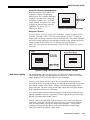
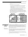
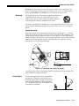
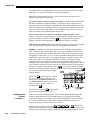
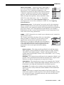
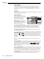
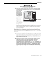
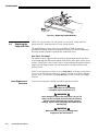
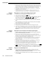
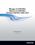
Screen Type ' Front Screen Installations
While there are two basic screen types, flat and curved, generally flat screens are
recommended for this projector. Flat screens offer a gain of about 1 with a viewing
angle just less than 180°. Incident light reflects equally in all directions so the
audience can see the display from various angles. Because of the low gain, flat
screens are most effective when ambient lighting is reduced, although this difference
may be negligible given the high brightness output from this projector.
Figure 2.1. Audience Coverage with Flat Screen
NOTE: Lenses for this projector are designed primarily for use with flat screens, but
the projector depth-of-field range allows the lens to be focused on curved screens as
well. While focus remains sharp in the corners, there may be significant pincushion
distortion, primarily at the top of the screen.
Rear Screen Installations
There are two basic types of rear screens: diffused and optical. A diffused screen has
a surface which spreads the light striking it. Purely diffused screens have a gain of
less than 1. The main advantage of the diffused screen is its wide viewing angle,
similar to that of a flat screen for front screen projection. Optical screens take light
from the projector and redirect it to increase the light intensity at the front of the
screen. This reduces it in other areas. A viewing cone, similar to that of a curved
front screen installation, is created.
DLV1280 DX User’s Manual
2-3
INSTALLATION AND SETUP
To summarize, optical screens are better suited for brightly lit rooms where the
audience is situated within the viewing cone. Diffused screens may be better suited
when a wide viewing angle is required but there is low ambient room lighting.
Screen Size ' Screen size may be from 5 to 40 feet diagonal, depending on lens you are using. For
instance, a 1.2:1 lens can produce a 5 to 30 foot image size, whereas a 4-7:1 zoom
lens produces an 8 to 40 foot image size. Choose a screen size which is appropriate
for your lens and application—for this projector, it is likely the standard 1.2:1 lens.
Keep in mind that if the projector will be displaying much text information, the
image size must allow the viewer to recognize all text clearly. The eye usually sees a
letter clearly if eye-to-text distance is less than 150 times the height of the letter.
Small text located too far from the eye may be illegible at a distance no matter how
sharply and clearly it is displayed.
To fill a screen with an image, the aspect ratio of the screen should be equal to the
aspect ratio of the image. The aspect ratio of an image is expressed as the ratio of its
width to its height. Standard video from a VCR has a 4:3 (or 1.33:1) aspect ratio. For
example, to display a VCR output with a 4:3 aspect ratio onto a 10 foot (3m) high
screen, the width of the screen must be at least 13.3 feet (4m).
Note: Screen size is often specified as diagonal size. Traditionally, screens specified
by diagonal size have aspect ratios of 4:3. Screens with other aspect ratios (such as
those recommended for this projector) are not typically specified by diagonal size.
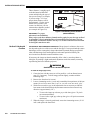
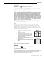
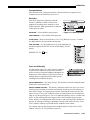
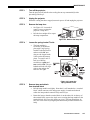
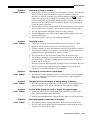
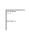
Screen Aspect Ratio ' Aspect ratio describes the
proportion of the screen or
image, and is expressed as
the ratio of width to
height—such as “4:3” or
“5:4” (see right). Although
image size and image
aspect ratio can both be
adjusted quickly through
projector software, it is still
Figure 2.2. Aspect Ratios of 4:3 and 5:4
a good idea to choose a
screen aspect ratio which is most appropriate for your intended applications. Ideally,
to exactly fill a screen with an image, the aspect ratio of the screen should be the
same as the aspect ratio of the image, which can depend on the source in use. For
example, standard video from a VCR has a 4:3 ratio (approximately), whereas a high
resolution graphics signal typically has a 5:4 aspect ratio. By default, DLV1280 DX
images will be as large as possible and, with the exception of graphics sources, will
maintain their aspect ratio.
Note that with a few exceptions, sources with less than 1280 x 1024 resolution have a
4:3 aspect ratio. The normal aspect ratio for 1280 x 1024 sources is 5:4.
2-4
DLV1280 DX User’s Manual
INSTALLATION & SETUP
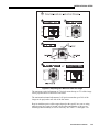
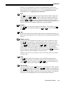
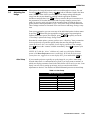
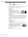
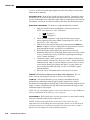
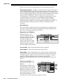
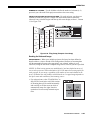
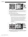
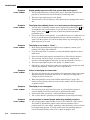
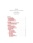
Using a 5:4 Screen (recommended)
With one exception, XGA images will—
by default—resize to 5:4 and fill an
SXGA screen. The exception (illustrated
in Figure 2.3) is that video signals will
retain their 4:3 aspect ratio—to fill the
screen, increase Vertical Stretch in order
to slightly expand the image at the top
and bottom. For details, see 3.6,
Adjusting the Image.
Figure 2.3. Adjusting a Video Image
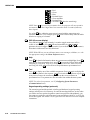
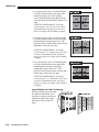
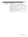
Using a 4:3 Screen
If you are using a 4:3 screen, images will—by default—slightly overlap the screen
vertically. To remedy, reduce Vertical Stretch so that the “too tall” 5:4 image no
longer spills over the top or bottom of the screen (Figure 2.4). This control eliminates
the need for simply moving the projector father from the screen, which would result
in black borders for all sources. See 3.6, Adjusting the Image for details.
NOTE: The Vertical Stretch adjustment may soften the image slightly, but is rarely
noticeable.
Figure 2.4. Using a 4:3 Screen for a Mix of 5:4 and 4:3 Images
Ideal Room Lighting ' The high brightness output of this projector is certainly well suited for locations
where ambient lighting is less than optimum for projection, yet there are still many
simple things you can do to further optimize your installation.
Visiting a movie theater can give you an idea of what makes an ideal projection
environment. Walls, floors and furnishings are dark and matte finished. A projection
room should not have white reflective ceilings or non-directional lighting such as
fluorescent lights. The white ceiling spreads light, making the room appear brighter.
Keep lighting and reflections to a minimum.
If it is not possible to eliminate fluorescent lights, consider using incandescent spot
lighting or parabolic reflectors ("egg crates") to direct light down to the floor. Light
dimmers or rheostats allow further control.
Outside windows are undesirable in any projection room. A small crack between
curtains on a sunny day can wash out a projected image. If you do have windows,
make sure that window coverings are opaque and overlapping — some window
coverings are designed to provide up to 100 percent blockage of outside light.
Ideally, the material should have a matte finish.
DLV1280 DX User’s Manual
2-5
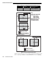
INSTALLATION AND SETUP
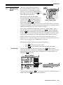
To minimize the effects caused by unwanted light from door and aisle ways,
carefully choose the position of your projector and screen. Figure 2.5 shows an
installation where poor screen placement allows too much unwanted light to enter the
screen. In Figure 2.6, screen and the projector are positioned so that unwanted light is
minimized.
Figure 2.5. Poor Screen Placement
Figure 2.6. Better Screen Placement
Even with all lighting removed it is still possible that room reflections within the
room can slightly degrade the image. Light from the projection screen should be
absorbed by the ceilings, walls and floors so that it will not be reflected back to the
screen. Again, keep reflective surfaces to a minimum.
Other Considerations ' Here are some other considerations and tips which can help you improve your
installation:
2-6
DLV1280 DX User’s Manual
•
Ventilation is an important factor when preparing a projection room. The ambient
temperature should be kept constant and below 35°C (95°F). Keep the projector
away from heating and/or air conditioning vents. Changes in temperature can
cause drifts in the projector circuitry which may affect performance.
•
Keep the projector away from devices which radiate electromagnetic energy such
as motors and transformers. Common sources of these are slide projectors,
speakers, power amplifiers, elevators, etc.
INSTALLATION & SETUP
•
For rear screen applications, less space is required if a mirror is used to fold the
optical path.
•
Choose the right screen size for the application:
◊
◊
◊
•
As screen size increases, magnification increases and reduces brightness.
Select a screen size which is appropriate for the venue, but not larger
than that required.
Installing a large screen in a small room is similar to watching television
close up; too large a screen can overpower a room. A good rule of thumb
is to be no closer than 1.5 times the width of the screen.
Larger screens require greater attention to lighting conditions.
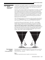
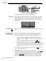
When laying out the projection room, consider positioning the projector and
screen in a manner which will achieve maximum audience coverage and space
efficiency. For example, placing the screen along the larger wall in a rectangular
room will reduce audience coverage. Figure 2.7 shows two examples of how
audience coverage is maximized.
Figure 2.7. Screen Locations for Maximum Audience Coverage
2.3
Projector
Position and
Mounting
Installation type, screen type, and lighting all affect where the projector is positioned.
In addition, both throw distance (the distance between the projector and screen) and
vertical position (the height of the projector in relation to the screen) must be
determined for every new installation. Both depend on the screen size and lens type
you are using. Make sure that the room can accommodate the required position of the
projector for the chosen screen size.
Throw Distance ' Throw distance is the distance between the projector's front feet and the screen. For
any installation, an accurate throw distance must be determined in order for the
image to be of the right size for your screen–the farther the projector is from the
screen, the larger the image.
NOTE: If your projector is tilted in relation to the screen, as is sometimes the case
for large venues or elevated installations, throw distance still represents the smallest
measurement between the screen and front feet.
DLV1280 DX User’s Manual
2-7
INSTALLATION AND SETUP
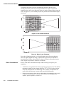
Throw distance is roughly equal
to the horizontal width of the
screen multiplied by the type of
lens you are using. For example,
if you are using a 1.2:1 lens,
proper throw distance will be
approximately 1.2 x the screen
width. Once you know your
screen size and lens, you can
estimate throw distance needed
(see example in Figure 2.8).
Figure 2.8. Estimating Throw Distance
IMPORTANT:
For proper
(SEE APPENDIX E)
placement in an installation,
always refer to the throw distance formula and/or graph for your lens type as listed
in Appendix E. Keep in mind that due to lens manufacturing tolerances for lens
focal length, actual throw distance can vary ±5% or more between lenses described
as having the same throw ratio.
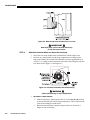
Vertical & Horizontal ' THE VERTICAL AND HORIZONTAL POSITION of the projector in relation to the screen
Position
also depends on the size of the screen and the lens type. Correct position helps ensure
that images will be rectangular in shape rather than keystoned (having non-parallel
sides) and that image focus and brightness both remain optimized. Ideally, the
DLV1280 DX lens should be centered with the screen.
If necessary, the image can then be manually offset—that is, moved up/down or
left/right—by making a slight mechanical adjustment to the lens mount (essentially
repositioning the lens within the projector).
WARNING
Qualified service technician required.
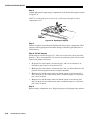
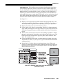
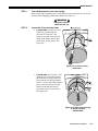
To offset the image (Figure 2.9):
1. Center the lens with the screen as well as possible—refer to dimensions on
page 5-3 if necessary. To shift image position slightly, continue with the
remaining steps.
2. Remove the front bezel (6 screws).
3. Loosen 4 mounting screws (½ turn only) around the front perimeter of the lens
mount. Do not loosen more than ½ turn, or you will create too much “play”.
4. With a flat screwdriver, pry in the adjustment slots as necessary to slide the
lens mount in the direction desired (maximum amount of movement in any
direction is approximately 1/8”).
• To move the image up or down, pry at side slots (gives ±70 pixels
movement maximum).
• To move left or right, pry at the top slot (gives ±50 pixels movement
maximum)
5. When the image is correctly positioned, secure the 4 mounting screws (15-18
in.lb.) and replace the front bezel.
2-8
DLV1280 DX User’s Manual
INSTALLATION & SETUP
Figure 2.9. Adjusting Lens Mount to Offset the Image
The maximum vertical adjustment of ±70 pixels means that up to 57% of the image
can be projected above or below the lens center.
The maximum horizontal adjustment of ±50 pixels means that up to 54% of the
image can be projected to one side of the lens center.
Keep in mind that precise offset ranges depend on the specific lens you are using,
where the true lens center is located without offset, and whether or not you are
offsetting both horizontally as well as vertically. See Table 2.1 and Figure 2.10.
DLV1280 DX User’s Manual
2-9
INSTALLATION AND SETUP
Table 2.1. Maximum % of Image Offset from Lens Center (ANY LENS)
Max. Offset
(distance in pixels)
= Amount of Image Offset
from Lens Center
Vertical Offset
±70 pixels
Horizontal Offset
±50 pixels
= 57% (i.e., ±582 pixels)
= 54% (i.e., ±690 pixels)
Figure 2.10. Vertical and Horizontal Offsets
NOTES: 1) If you cannot raise or lower the image enough using mechanical vertical
offsets, try adjusting V-Position in the Size and Position menu (see 3.6, Adjusting
2-10
DLV1280 DX User’s Manual
INSTALLATION & SETUP
the Image). 2) If the image becomes keystoned or exhibits uneven brightness, the
projector may simply be poorly placed in relation to the screen. 3) Simultaneously
offsetting horizontally and vertically limits the adjustment range of each.
Mounting ' For typical front or rear floor mounts, mount the projector on a
secure table or cart. Take care with a mobile cart—avoid
sudden stops, excessive force and uneven surfaces that may
cause the projector and cart combination to overturn.
The table or cart should be reasonably level. Fine adjustments to the projector level
can be made by adjusting the height of the projector legs; refer to 2.7, Leveling for
details.
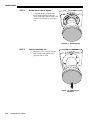
Special Mounting
Note that projector can be rotated and mounted at any vertical angle—i.e., you can
tilt the face of the projector up or down as much as desired for your installation. The
side-to-side tilt, however, must not exceed 15° (see Figure 2.11). This limit ensures
that the arc lamp in the projector operates properly and safely. Always make sure that
exhaust air from the projector does not vent towards the lens, otherwise you may
detect heat waves in your projected image.
Figure 2.11. Horizontal and Vertical Tilt Ranges
You must use the proper ceiling mount fixture or stacking kit for your projector. For
more information, contact your dealer.
Folded Optics ' In rear screen applications where space behind
the projector is limited, a mirror may be used
to fold the optical path. See right. The position
of the projector and mirror must be accurately
set—if considering this type of installation, call
your dealer for assistance.
DLV1280 DX User’s Manual
2-11
INSTALLATION AND SETUP
2.4
Source
Connections
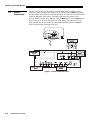
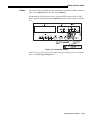
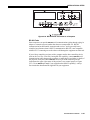
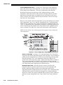
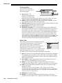
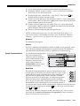
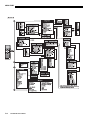
The rear panel of the projector provides standard input panels to which you may
connect a variety of sources. See Figure 2.12–the lower left area (INPUT 1) typically
accepts an RGB signal from an external RGB source, or it can also be used for YPbPr
signals or additional video sources. The upper right panel–the optional Video
Decoder Module–accepts only composite video at INPUT 3 or S-video at INPUT 4 from
devices such as VCRs, laser disk players or DVD players. There are also several
other optional interfaces available for connecting an additional source at INPUT 2.
Such an option installs in the upper left area.
Figure 2.12. Rear Connector Panel
2-12
DLV1280 DX User’s Manual
INSTALLATION & SETUP
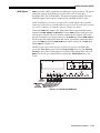
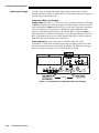
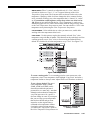
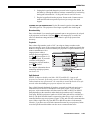
RGB Signals ' INPUT 1 provides 5 BNCs (connectors) for linking to a variety of sources. The typical
connection would be to an RGB source such as VGA, SVGA, XGA, Mac,
PowerMac, DEC, Sun, SGI and others. This projector supports multiple sync types
with RGB signals: sync-on-green, composite sync, and separate H & V syncs.
NOTE: Depending on the source, you may need a custom adapter cable with BNC
connectors at the projector end and a different type of connector at the other (such as
a 15-pin "D" connector for computer sources). Contact your dealer.
Connect the SYNC BNC input(s) first. Then connect the red, green and blue source
outputs to the RED, GREEN, and BLUE BNCs on the INPUT 1 panel. If the source uses
sync-on-green, only the red, green, and blue connections are required. If the source
provides a composite sync output, connect it to the SYNC input labeled HOR/COMP. If
the source provides separate horizontal and vertical sync outputs, connect horizontal
sync to the SYNC input labeled HOR/COMP and connect vertical sync to SYNC input
labeled VERT. See Figure 2.13.
NOTES: 1) If for some reason the projector fails to recognize as an RGB signal,
specify this Color Space option within the Image Settings menu. See 3.6, Adjusting
the Image. 2) To connect YPbPr signals–such as from DVD or analog HDTV sources–to
INPUT 1, use the red, green and blue BNCs as described in YPbPr Signals later in this
section.
Figure 2.13. Connecting RGB Input
DLV1280 DX User’s Manual
2-13
INSTALLATION AND SETUP
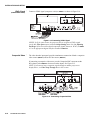
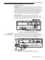
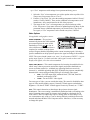
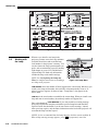
YPbPr Signal ' Connect a YPbPr signal (component video) to INPUT 1 as shown in Figure 2.14.
(COMPONENT VIDEO)
Figure 2.14. Connecting YPbPr Signal
NOTES: 1) If, for some reason, the projector fails to recognize a YPbPr signal,
specify this Color Space option within the Image Settings menu. See 3.6, Adjusting
the Image. 2) Do not connect digital component signals (known as YCbCr) to INPUT
1. Use the appropriate digital interface installed at INPUT 2.
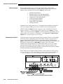
Composite Video ' The video decoder input panel provides simultaneous connection of both a composite
video source (INPUT 3) and an S-Video source (INPUT 4).
If connecting a composite video source, use the Composite BNC connector or the
RCA phono jack at INPUT 3–do not use both as inputs. See Figure 2.15.
NOTE: If you want to loop a composite signal through to another projector or
display device, see Video Loop Through later in this section.
Figure 2.15. Connecting Composite Video
2-14
DLV1280 DX User’s Manual
INSTALLATION & SETUP
S-Video ' The video decoder input panel provides simultaneous connection of both a composite
video source (INPUT 3) and an S-Video source (INPUT 4).
If connecting an S-Video source, use the 4-pin mini DIN connector or the Y and C
BNC connectors (luma and chroma) at INPUT 4–do not use both as inputs. See Figure
2.16.
Figure 2.16. Connecting S-Video
NOTE: If you want to loop an S-video signal through to another projector or display
device, see Video Loop Through below.
DLV1280 DX User’s Manual
2-15
INSTALLATION AND SETUP
Video Loop Through ' To loop a single incoming video signal input (connected at the video decoder)
through to another projector or display device, use the empty connector(s) adjacent to
this same input as described below.
Composite Video Loop Through
CONNECTIONS: See Figure 2.17. From your source, connect a composite video signal
to INPUT 3 using either the small phono plug or the adjacent BNC. Connect a second
cable from whichever INPUT 3 connector is free to one of the composite video inputs
of the next display device or projector. Continue this looping method for each
projector, using either the phono plug or the adjacent BNC as input into INPUT 3,
then using the other connector as an output (i.e., loop through). Whether you use the
BNC or the phono plug as input or output depends on the type of cable you have on
hand and what type of connectors are on each end.
VIDEO TERMINATION:
In the Video Options submenu, make sure “Video
Termination” is checked for the final projector only. All other projectors must have
this option unchecked in order for the signal to continue. For other types of display
devices in the chain, typically a “Hi-Z” switch position is needed.
Figure 2.17. Connections for Composite Video Loop Through
2-16
DLV1280 DX User’s Manual
INSTALLATION & SETUP
S-Video Loop Through
CONNECTIONS: See Figure 2.18. From your source, connect an S-video source signal
to INPUT 4 using either the 4-pin mini DIN or the 2 adjacent BNCs labeled Y and C.
Connect a second cable from whichever INPUT 4 connector is free to one of the Svideo inputs of the next display device or projector. Continue this looping method for
each projector, using either 4-pin mini DIN or the 2 adjacent BNCs as input into
INPUT 4, then using the other connector(s) as an output (i.e., loop through). Whether
you use 4-pin mini DIN or the 2 adjacent BNCs as input or output depends on the
type of cable you have on hand and what type of connectors are on each end.
VIDEO TERMINATION: In the Video Options submenu, make sure “Video
Termination” is checked for only the final projector. All other projectors must have
this option unchecked in order for the signal to continue. For other types of display
devices in the chain, typically a “Hi-Z” switch position is needed.
Figure 2.18. Connections for S-Video Loop Through
Extra Video ' If you want to use an extra video source in addition to the video source(s) connected at
INPUT 3 or INPUT 4 connect either a Composite or S-Video source to INPUT 1 as shown in
Figure 2.19. Do not connect both types here simultaneously. NOTE: For additional video
inputs, install an optional Composite/S-Video Input Module at INPUT 2.
– COMPOSITE OR S-VIDEO
Figure 2.19. Connecting an Extra Video Source to Input 1
DLV1280 DX User’s Manual
2-17
INSTALLATION AND SETUP
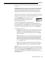
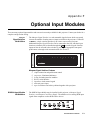
Optional Inputs ' Optional modules allow you to increase your total number of inputs and/or
accommodate different signal types, whether analog or digital. Any one of these
modules can be installed in the area labeled INPUT 2. They include:
•
•
•
•
•
•
•
•
RGB 500 Input Module
RGB 400 Active Loop Thru Input Module
RGB 400 Buffered Amplifier Input Module
Composite/S-Video Input Module
PC250 Analog Input Module
Serial Digital Input Module
Digital HDTV Input Module
DVI Input Module
Alternatively, the analog interfaces (i.e., non-digital) can be installed in a Marquee
Case/Power Supply or Marquee Switcher, if desired, for use with the projector.
NOTES: 1) Optional digital interfaces cannot be used in a Marquee Case/Power
Supply or Switcher. 2) Connect analog HDTV signals directly to INPUT 1 or to any
“RBG” input module installed at INPUT 2— the optional HDTV Input Module used in
earlier models is not needed or recommended . 4) See Appendix F, Optional Input
Modules for a brief description of each interface.
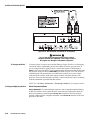
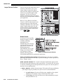
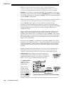
Connecting a switcher ' You may wish to use one or more external Marquee Signal Switchers or a third party
switcher in order to significantly increase the number of sources you can select. If
you are using a Marquee Signal Switcher, connect the switcher’s RGB output to
INPUT 1 and connect an RS-232 serial communication cable between the switcher and
the projector serial port labeled SWITCHER (see Figure 2.20). The switcher
communication link (permanently set at 9600 baud) enables you to access inputs
connected to the switcher in the same manner as those connected directly to the
projector. For most other third-party switchers, connect and access sources according
to the documentation provided with that switcher.
NOTE: Make sure any Marquee Signal Switcher connected directly to the projector
is set as “Switcher #1”. If it is not, unplug the switcher and turn the thumbwheel to
“1” before plugging back in and connecting to the projector and/or network.
Figure 2.20. Connecting a Marquee Signal Switcher
2-18
DLV1280 DX User’s Manual
INSTALLATION & SETUP
Connecting Multiple ' If you are using more than one Marquee Signal Switcher, daisy-chain the RS-232
Switchers
switcher inputs/outputs together to form a complete network of inputs accessible
from the projector (you can network up to 9 switchers), and connect Switcher #1 to
the projector as shown in Figure 2.20. In addition, connect the RGB output from each
switcher to its matching slot on switcher #1–for example, connect the RGB output
from switcher #2 to slot #2 on switcher #1, and the RGB output from switcher #3 to
slot #3 on switcher #1. Note that slots used in this manner on switcher #1 are no
longer recognized as inputs to the projector–if you select a slot location that is
connected to another switcher’s RGB output, the projector will display the “no input
signal” error message.
2.5
Power
Connection
Plug the projector’s high-current 13-amp rated line cord into the line input socket
located in the lower right corner of the rear panel of the projector, then plug the 3pronged end of the line cord into a grounded AC outlet. Input voltage to the projector
must be capable of supplying between 100 and 240 VAC, 50 or 60 Hz. The power
source must be capable of supplying 860 watts of power to the projector. See Section
5, Specifications for all power requirements.
WARNING
Do not attempt operation if the AC supply and cord are
not within the specified voltage and power range.
Caution: Once the projector is turned off, the lamp cooling fans will continue to
run for approximately five minutes to ensure that the projector and lamp have
sufficiently cooled, at which point the fans will automatically shut off. To avoid
thermal stress to the lamp, never unplug the line cord while the lamp cooling fans are
running. Do not unplug the projector in order to power down.
2.6
Operating
Orientation
The projector is set up at the factory for use in a front screen, floor mount orientation.
If your initial installation is ceiling mount or rear screen, displayed images may be
upside down and/or reversed. To correct, you must change the image orientation
from within the Menu
Preferences menu (you may
prefer to do this before
physically installing the
projector in its final
position/orientation).
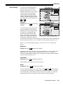
In the Menu Preferences
menu, highlight and select
the "Image Orientation" pulldown list. Select from Rear,
Inverted Rear, Front or
Inverted Front according to
your intended installation.
See Section 3, Operation for
further information.
DLV1280 DX User’s Manual
2-19
INSTALLATION AND SETUP
For most installations, the
lens surface of the projector
is parallel to the screen—this
prevents major keystoning of
the image (i.e., an image
with non-parallel sides). In
addition, the projector must
be kept level from side-toside in order for the lamp to
Figure 2.21. Adjusting the Feet Height
function safely. To make
small corrections to the projector's level, rotate each leg as necessary to raise or
lower. For angled installations, see “Special Mounting” under 2.3, Projector Position
and Mounting earlier in this section.
2.7
Leveling
2.8
Zoom, Focus &
quick lens adjustments.
Lens Offset
Zoom ' If you have a zoom lens installed, turn the textured ring of the lens barrel to decrease
Once the projector is properly set up and producing an image, you are ready to make
or increase the size of the image at the current throw distance. NOTE: Do not touch
the lens surface.
Focus ' At the lens opening, turn the focus tab until the image is as sharp as possible.
Lens Offset ' The projector should be positioned so that the lens is centered with the screen. If you
need to offset the image, see 2.3, Projector Position and Mounting for full details.
Lens offset ranges are also listed on page 5-1.
Further display adjustments are available through keypad commands and on-screen
menus—refer to Section 3, Operation.
2.9
Serial Port
Connections
NOTE: Communication software is required for serial control. Contact your dealer
for details.
You may wish to use equipment other than the keypad for controlling the projector or
for performing other special functions. Such equipment—such as most personal
computers—requires a serial interface for sending and receiving communications
through the serial ports on the projector. Note that there are two different types of
serial communication ports on this projector as described below.
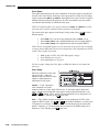
If using a computer ' RS-232 Ports
From most computers, connect an RS-232 serial communication cable between the
computer and the projector serial port labeled RS-232 IN—this 9-pin D connector port
is located near the bottom center of the projector's rear control panel (see Figure
2.22). Then set the projector baud rate to match that of the computer (changing the
baud rate is described in 3.7,Configuring System Parameters).
NOTE: Refer to Appendix D for complete cable wiring details.
2-20
DLV1280 DX User’s Manual
INSTALLATION & SETUP
Figure 2.22. RS-232 Serial Connection to a Computer
RS-422 Ports
Some computers can provide RS-422 serial communications (often through a plug-in
adapter or external converter) rather than the more common RS-232. RS-422
communication has differential “transmits-and-receives” and is generally better
suited for long distances than is RS-232 communication. RS-422 is not compatible
with RS-232—connecting one to the other could damage the equipment at either end.
If you wish to control the projector with a computer and/or other controlling device
(such as the Two-Way Controller) having RS-422 capability, connect RS-422 serial
communication cables between the computer (or other device) and either (or both) of
the projector serial ports labeled RS-422—these 6-pin XLR connector ports are
located near the upper right corner of the projector's rear control panel (see Figure
2.23). Use an RS-422 port only if your equipment has RS-422 capability—always
first consult the documentation supplied with your equipment.
DLV1280 DX User’s Manual
2-21
INSTALLATION AND SETUP
Figure 2.23. RS-422 Serial Connection to a Computer
WARNING
Do not use an RS-422 port unless you are using a
computer with RS-422 capability. The voltage levels of
this signal can damage incompatible equipment.
If using a switcher ' You may wish to use one or more external Marquee Signal Switchers or a third party
switcher in order to significantly increase the number of sources you can select. If
you are using a Marquee Signal Switcher, connect the switcher’s RGB output to
INPUT 1 and connect an RS-232 serial communication cable between the switcher and
the projector serial port labeled SWITCHER (refer back to Figure 2.20). The switcher
communication link (permanently set at 9600 baud) enables you to access inputs
connected to the switcher in the same manner as those connected directly to the
projector. For most other third-party switchers, connect and access sources according
to the documentation provided with that switcher.
NOTE: See 2.4, Source Connections, “Connecting a Switcher” for complete details.
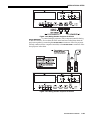
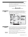
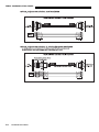
If using multiple projectors ' Serial Communications
RS-232 NETWORK: To control multiple projectors with a computer/controller having
an RS-232 interface, first set them all to the same baud rate needed, then chain the
projectors together by connecting the RS-232 OUT connector of the first projector
(already connected to the computer/controller) to the RS-232 IN connector of the next
projector in the chain.
2-22
DLV1280 DX User’s Manual
INSTALLATION & SETUP
Figure 2.24. Adding Another Projector via RS-232
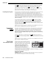
RS-422 NETWORK: To
control multiple projectors with a computer/controller having
an RS-422 interface, first set them all to the same baud rate needed, then chain the
projectors together by connecting the RS-422 PORT 2 connector of the first projector
(already connected to the computer/controller) to the RS-422 PORT 1 connector of the
next projector in the chain.
Figure 2.25. Adding Another Projector via RS-422
DLV1280 DX User’s Manual
2-23
INSTALLATION AND SETUP
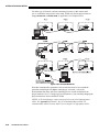
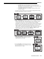
For either type of network, continue connecting projectors in this manner until
you’ve reached the last projector in the chain, so that only the last projector has an
empty RS-232 OUT (or RS-422 PORT, if applicable). See examples below.
Figure 2.26. Assorted Networks
Note that communication parameters such as baud rate must be set to match the
particular controlling device before connecting as a network—refer to the
documentation that came with your controlling device in order to determine the
proper baud rate. See 3.7, Configuring System Parameters if you need help changing the
projector baud rate from its default of 19200.
NOTES: 1) To avoid damage, connect only properly wired serial communication
cables. See Appendix D for details. 2) It is recommended that each RS-232
communication cable be no more than 25 feet in length. Use high quality cables.
2-24
DLV1280 DX User’s Manual
INSTALLATION & SETUP
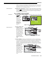
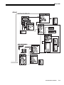
Back-up or “Split” Networks' In a typical network, broadcast serial communications or messages destined for a
specific projector travel through all serial ports in each projector regardless of
whether the messages originate from an RS-232 or RS-422 source (refer back to
Figure 2.26, bottom example). The communication path depends on the serial cabling
connected at each projector.
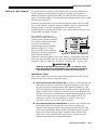
You may prefer the option of two separate communication paths—RS-232 or RS422—in your network, essentially creating a redundant “back-up” communication
path that can take over should a failed projector (or controller) prevent
communications via the other path. For this setup, connect each projector to the next
using both RS-232 and RS-422 ports.
Then enable the “Split Network”
setting in the Communications menu
for each projector present so that RS232 communications remain on RS232 paths only and RS-422
communications remain on RS-422
paths only (Figure 2.27). Each
projector can then receive and send
either type of message depending on
Figure 2.27. Enable “Split Network”
which controller initiates the
commands—should one path fail, the second “back-up” network path can be used.
Only one network should be active at a given time, as determined by the controller
(whether it is RS-232 or RS-422). Note that the “Broadcast Key” option is OFF.
IMPORTANT
Whenever downloading new projector software to networks, use a
single-route network only. DISCONNECT any redundant serial cabling
and UNCHECK the “Split Network” checkbox for each projector.
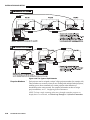
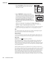
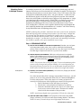
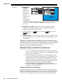
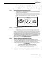
Two Different “Splits”
There are two different split network configurations possible (Figure 2.28). Set up
whichever option best suits your application needs:
A.
SPLIT NETWORK WITH ONE CONTROLLER– If
B.
SPLIT NETWORK WITH TWO CONTROLLERS– If you have two controllers (one
RS-232 and one RS-422) and want one to be a back-up, connect each
controller to the appropriate port on the first projector in the network. Then
connect projectors together using both RS-232 and RS-422 ports as shown.
Make sure the “Split Network” option is enabled in the Communications
menu. Now, if either controller fails, you can simply switch to the other
controller and communicate via the other standard.
you have a single controller and
want a back-up serial link, connect one controller standard (e.g., RS-232) to
one physical end of the network and the other controller standard (e.g., RS422) at the other physical end of the network. Make sure the “Split Network”
option is enabled in the Communications menu. If a projector should then fail
anywhere in the network, communication with the remaining projectors can be
resumed in the opposite direction using the other standard. NOTE: This
configuration requires that both standards be available from a single
controller, or that you use an RS-232/RS-422 adapter.
DLV1280 DX User’s Manual
2-25
INSTALLATION AND SETUP
Figure 2.28. Two Types of Split Networks
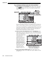
Projector Numbers ' Each projector can be assigned a unique 3-digit projector number (for example, 001).
These numbers are necessary when you are working with multiple linked projectors,
enabling you to direct commands to a certain projector rather than always
broadcasting to the entire network. For complete information on how to assign
projector numbers, see 3.7, Configuring System Parameters.
NOTE: To loop a single incoming video source through to another projector or
display device on a network, see Video Loop Through in 2.4, Source Connections.
2-26
DLV1280 DX User’s Manual
INSTALLATION & SETUP
2.10
Keypad
Protocols and
Conversion
At manufacture every keypad is assigned “A” as its default protocol, which is simply
a collection of settings that determine how the keypad operates. Once assigned, this
protocol remains in effect until it is changed—that is, the keypad will operate as it
currently does until you change its protocol.
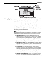
Protocols are most useful for multiple-projector applications. For example, you might
want to change a keypad protocol if you are working with two projectors and two
remote keypads in the same room and need to control each projector independently
(Figure 2.29). When Keypad A has a different protocol than Keypad B, each keypad
communicates only with the projector having a matching protocol. Or, if you have a
network of two or more projectors connected together via RS-232 serial ports, you
may want only certain projectors to respond to a wired keypad, thus you can use
different protocols to limit responses.
NOTE: Matching the protocol on the projector to that of a keypad is done through a
setting in the Communications menu. See 3.7, Configuring System Parameters for
further information on how to change the projector's infrared sensor protocol.
A protocol for either type of remote keypad — IR or wired — can be changed
through software commands entered on the keypad. A new protocol set through
software commands remains in effect until the keypad batteries are removed and
replaced (if an IR remote), or until the keypad is unplugged (if a wired remote). A
remote can also be changed manually —you can "hard-wire" new jumper settings
inside the keypad so that they remain in effect until you change the hard-wiring. Note
that a hard-wired protocol can be temporarily overridden by the software protocol
change, effective until the keypad is unplugged and plugged in again (if a wired
remote) or until a battery is removed (if an IR remote).
Figure 2.29. Independent Keypads and Projectors
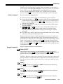
Remote Keypad ' The standard IR remote keypad or the optional wired remote can be set to one of two
Protocol
different protocols — “A” or “B”. To hard-wire a protocol to “A” or “B” in either
— IR OR WIRED KEYPAD —
remote, follow Steps 1 through 5:
Step 1
Unplug the keypad from the projector (applies to wired remote only).
DLV1280 DX User’s Manual
2-27
INSTALLATION AND SETUP
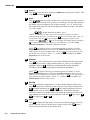
Step 2
Unlatch and open the empty battery compartment on the back of the keypad as shown
in Figure 2.30.
NOTE: A wired keypad opens as shown, but a cable passes through the battery
compartment cover.
Figure 2.30. Opening the Keypad
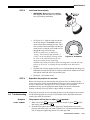
Step 3
Find the 4 jumpers located along the latching side of the battery compartment. These
jumpers set the keypad protocol and other settings so that the keypad functions in a
certain manner.
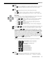
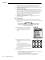
Step 4: Set the Jumpers
Set the jumpers as shown in Figure 2.31. Take care to refer to the correct part of the
drawing — IR or wired (optional). Use tweezers or needle-nose pliers to remove and
replace each jumper as necessary.
•
J1 jumper: For either remote, set between pins 1 and 2 to set as Protocol “A”.
Set between pins 2 and 3 to set as Protocol “B”.
•
J2 jumper: For either remote, set between pins 2 and 3 as shown; otherwise, the
projector will not respond correctly to keypad commands.
•
J3 jumper: For the IR remote, make sure that the jumper is set between pins 2
and 3 as shown. For the wired remote, make sure that the jumper is set between
pins 1 and 2 as shown.
•
J4 jumper: For the IR remote, make sure that the jumper is set between pins 1
and 2 as shown. For the wired remote, make sure that the jumper is set between
pins 2 and 3 as shown.
Step 5
Replace battery compartment cover. Plug into projector (wired keypad only) and test.
2-28
DLV1280 DX User’s Manual
INSTALLATION & SETUP
Figure 2.31. Locating and Setting the Jumpers
NOTE: A wired keypad can be converted into an IR remote keypad, and vice versa.
Follow the settings shown above, adding or deleting the cable and batteries as required.
The cable with 3-pin XLR connector is available separately from your dealer.
SHORTCUT METHOD:
You can also issue software protocol settings through the keypad. These software
commands will be lost when the keypad is either unplugged or when a battery is
removed — the keypad will revert back to the hard-wired jumper settings (see above)
until you enter the software commands again.
Press
Input1
Color
Pixel
Position
= Protocol “A”
Press
Input1
Color
Pixel
Position
= Protocol “B”
NOTE: If you change a keypad to a new protocol and the projector stops responding,
the projector is likely set to a conflicting protocol. To regain use of the keypad, either
change the keypad protocol back again, or use the opposing type of keypad (IR or
wired, as the case may be) to access the Communications menu. Under “Front IR”
or "Wired Keypad" (whichever you’ve just changed), select the protocol matching the
new protocol of this keypa d —the projector should now respond properly to that
keypad.
Converting a Keypad ' If desired, you can convert an IR remote keypad into a wired remote keypad and vice
versa.
TO CHANGE FROM INFRARED TO WIRED:
•
•
•
Remove battery compartment cover from back of keypad.
Remove batteries.
Wait 1-2 minutes.
DLV1280 DX User’s Manual
2-29
INSTALLATION AND SETUP
•
•
•
•
Plug the keypad cable (available separately) into the empty battery
compartment. Make sure that the battery cover is notched smoothly to
accommodate the cable.
Set keypad protocol as desired, using “wired” jumper settings.
Replace battery compartment cover.
Plug into the 3-pin XLR port at the rear panel of the projector.
TO CHANGE FROM WIRED TO INFRARED:
•
•
•
•
•
•
2-30
DLV1280 DX User’s Manual
Unplug the keypad from the projector.
Open the keypad back and unplug the keypad cable.
Wait 1-2 minutes.
Install batteries (see Section 4).
Set keypad protocol as desired, using “IR” jumper settings.
Replace battery compartment cover.
Section 3
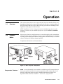
Operation
3.1
Overview
This section explains how to use the projector once it has been installed. Please read
through these pages before using the projector for the first time. An understanding of
projector features and how to access them will help you to take full advantage of the
capabilities of the projector within minutes.
NOTE: Installation involves locating the projector and adjusting it for use at that
location. If you have not yet installed the projector, refer to Section 2, Installation
and Setup.
3.2
Projector
Basics
Most projector functions and adjustments are entered through keypad commands that
either control the projector directly or activate a system of intuitive menus. Variations
in settings can be defined and retained in the projector's internal memory as a custom
channel, with up to 99 different channels possible.
Components and functions are illustrated below.
Figure 3.1. Basic Projector Components
Components / Features ' ZOOM - Accessed manually in some models or with the keypad if a motorized zoom
lens is present, the lens barrel of a zoom lens (optional) rotates to adjust the size of
the image without moving the projector. Minimum and maximum image sizes
depend on which zoom lens is installed — see Section 5, Specifications.
DLV1280 DX User’s Manual
3-1
OPERATION
FOCUS - Accessed
manually with tabs located at the lens, focus adjusts the sharpness
of the image at the current throw distance.
LENS OFFSET –See
Section 2, Installation and Setup for the procedure for
mechanically offsetting the lens mount. Offset ranges are listed on page 5-1.
INFRARED SENSOR - The infrared (IR) sensor on the front of the projector receives
infrared signals from the IR keypad for remote control of projector functions. For
proper operation make sure that the sensor is not blocked.
LAMP DOOR -
For accessing and replacing the lamp module. NOTE: Lamp
replacement requires a qualified service technician.
FILTER -
Remove and replace air filter as necessary.
COMPOSITE/S-VIDEO INPUT (OPTIONAL) - Accepts
a composite video and S-Video
signal from devices such as VCRs.
RGB INPUT - Accepts
RGB and sync signals from devices such as computers, as well
as composite video, S-Video or YPbPr component signals.
RS-232 SERIAL INTERFACE (WITH LOOP THROUGH) - Allows
one or more projectors to
be remotely controlled by a computer or controller, and provides a communications
connection for the Marquee Signal Switchers.
RS-422 SERIAL INTERFACE (WITH LOOP THROUGH) - Allows
one or more projectors to
be remotely controlled by an RS-422 compatible computer or controller (such as the
Two-Way Controller accessory). RS-422 communications can travel greater distances
than can RS-232 communications, but require RS-422 compatible equipment.
AC LINE CORD INPUT - Input power required is 100 - 240 VAC, 50 to 60 Hz @ 9
amps (@ 100 V). Use the line cord provided with the projector. See Section 5.
WARNING
Do not attempt operation if the AC supply is not within
the specified voltage and power range.
3-2
DLV1280 DX User’s Manual
OPERATION
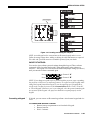
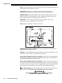
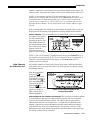
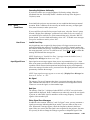
STATUS/POWER LEDS - Two
LEDs (light emitting diodes) located in the lower right
corner of the rear connector panel indicate projector "Status" (top) and "Power"
(bottom). During normal operation, the "Power" light is steady green and the "Status"
light flashes green each time a key is pressed or when the projector receives a serial
command. Use the following as a guide:
Figure 3.2. Reading the Status LEDs
NOTE: A steady red power light accompanied by a coded pattern of red and yellow
flashes from the status light indicates an internal system error. See 3.11, Error
Conditions. Should the problem persist, contact a qualified service technician
available through your dealer.
REMOTE WIRED KEYPAD CONNECTOR (3-pin XLR) -
For optional tethered remote
control of the projector.
HARD RESET -
Emergency access for powering down the projector in the event of a
system failure. Insert a pen point or small screwdriver.
3.3
Using the
Keypad
The keypad appears in two locations:
•
•
Infrared (IR) Remote for tetherless control up to 100 feet away
Wired Remote (optional) tethered to the rear of the projector
While either keypad is identical in layout and provides complete control of the
projector, you may find one keypad more convenient than the other for your specific
installation and application.
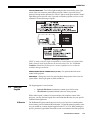
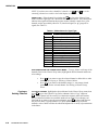
IR Remote ' The IR Remote Keypad controls the projector by way of wireless communications
from a battery-powered infrared (IR) transmitter. Use the IR remote keypad the same
way you would use a remote keypad supplied with a TV or VCR. When making key
presses, point the keypad either toward the screen or toward the front of the projector.
DLV1280 DX User’s Manual
3-3
OPERATION
The sensor on the projector will detect the signals and relay the commands for
internal processing.
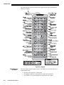
Figure 3.3. Keypad
Wired Remote ' The wired remote keypad connects to the 3-pin XLR jack via a 50 ft. cable. It is
—OPTIONAL—
recommended when:
•
•
•
3-4
DLV1280 DX User’s Manual
the front of the projector is inaccessible
the lighting conditions are unsuitable for proper IR transmission
you want to use a separate keypad for each projector in a group
OPERATION
NOTES: 1) For extra long distances and/or harsh environments, you may prefer to
use an optional remote Two-Way Controller to control the projector. For operating
details, please see the Two-Way Controller User’s Manual included with this
accessory. 2) Old VistaGRAPHX “Roadie style” keypads can be used with this
projector, but the Func key codes listed on the back are different and do not apply.
Guide to Keypads ' Keep in mind the following guidelines:
1) Press keys one-at-a-time; there are no simultaneous key presses required.
2) For any key having an “*” ( Power* , for example), hold the key for approximately 1
second in order to toggle the function with a single key press. For other keys (or
to use a “*” key in conjunction with ON or OFF ), a momentary press similar to
a mouse click is sufficient.
3) Press the “lightbulb key” to temporarily illuminate the keypad without sending
any other command.
4)
,
, ON , and OFF repeat their “arrow” actions when held down. For
other keys, release and press again to repeat an action. In a network, pause
between adjustments to ensure that the last projector can keep pace with the
commands.
5) If you press a key while the projector is busy with another action, such as during
a power-up, the key press may not take effect.
When you turn on the projector it begins operating at presentation level, such as an
image from the most recently used source signal. The projector temporarily leaves
presentation level whenever you use the keypad to work with control settings, display
menus, or on-line help. For example, pressing Menu after startup displays the main
menu — presentation level is no longer active, although the image still appears in the
background. Press Menu again (or Exit ) to return or leave the menu system and return
to presentation level.
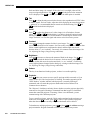
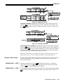
Keypad Commands ' Specific keypad commands are explained below:
Power*
Power ON/OFF
Press and hold for approximately 1 second to turn the projector on or off with a
single key press. Or press Power* followed immediately by ON or OFF if you want to
guarantee the correct toggle (useful if you are unsure of the present status).
NOTES: 1) Whenever the projector is turned off, the lamp cooling fans remain on for
about five minutes to cool the lamp. 2) It is a good idea to avoid turning a projector
back on until it has been off for a few minutes. Hot re-strikes of the lamp may reduce
lamp life.
Input1
Input2
Input3
Input 1
Press Input1 to select the source connected to INPUT 1 on the projector (data input).
This is the same as entering Input
.
Input 2
Press Input2 to select the source connected to INPUT 2 on the projector (an optional
.
interface). This is the same as entering Input
Input 3
Press Input3 to select the source connected to INPUT 3 on the projector (composite
video). This is the same as entering Input
.
DLV1280 DX User’s Manual
3-5
OPERATION
Input4
Input
Input 4
Press Input4 to select the source connected to INPUT 4 on the projector (S-Video). This
is the same as entering Input
.
Input
Press Input
when you want to display from a specific source location, such as a
switcher connected serially to the projector’s switcher port. The first digit represents
the number you have assigned to your switcher (usually 1-9, or “0” for one of the
four inputs on the projector). The second digit represents the switcher’s slot number
(1-9). For example:
Input
= display data from switcher 1, slot 2.
NOTES: 1) Although you don’t need to use the input key unless a switcher is
connected to the projector, you can also use Input to access the four input “slots” on
as the first digit (representing the projector as the
the projector itself: use
as the second digit (the desired input slot number).
switcher), then , ,
, or
in combination with higher numbers is an invalid entry. 2) See 3.5, Using
Channels and Inputs for a detailed explanation of inputs.
NOTE: Input key behavior during a presentation depends on whether or not the
Display Channel List option is selected in the Menu Preferences menu. You can
choose to have on-screen feedback when you press Input , or you may prefer to enter
the desired source location “blind”, i.e., without on-screen feedback. See Menu
Preferences later in this section.
Chan
Channel
Press Chan to select a specific source setup (channel) defined and stored in projector
memory. Once you enter a 2-digit channel number (or, if there is a list displayed,
highlight it and press Enter ), the display will automatically change and update
according to the numerous setup parameters defined for that channel.
NOTE: Chan key behavior during a presentation depends on whether or not the
Display Channel List option is selected in the Menu Preferences menu. You can
choose to use a scrollable list of channels when you press Chan , or you may prefer to
enter the desired channel number “blind”, i.e., without on-screen feedback. See
Menu Preferences later in this section.
Stby*
Menu
3-6
DLV1280 DX User’s Manual
Standby
Press Stby* and hold for approximately 1 second to blank all display output while
keeping the projector in a warmed-up and ready state. Or quickly press and release
Stby* and follow immediately by
ON or
OFF if you want to guarantee the correct
toggle (useful if you are unsure of the present status). Note that the lamp and
electronics remain ON in standby mode, even though the image turns to black and
most functions are disabled. To leave standby press and hold Stby* again (or use Stby*
OFF ). Or simply press Exit or Menu .
Menu
Press Menu to display the Main menu. A list of several options appears for access to
specific functions, such as Channel Setup or Image Settings. Press Menu again to
remove all menus and return to presentation level.
OPERATION
Enter
Exit
Enter
Press Enter to select a highlighted item, to toggle a checkbox (checked vs. unchecked),
or to accept a parameter adjustment and return to the previous menu or image.
Exit
Press
Exit
to return to the previous level, such as the previous menu.
NOTE: Exit does not save changes within text editing boxes (including number
editing of a slidebars) or within pull-down lists. It acts as a “cancel” in these cases.
Arrow Keys
The arrow keys have a variety of functions depending on the situation. Some typical
uses are described below. See also Editing Text later in Section 3.
•
•
•
ON
or
or
to change a slidebar value—hold as desired for continuous
Use
adjustment (note the adjustment increments and range depend on the
parameter being adjusted).
or
to change to a different option within a pull-down list
Use
without having to display the list first
Use
or
to jump between “pages”, such as in Help or lengthy pulldown lists.
Use the ON or OFF keys to navigate within a menu, pull-down list or text box, or to
increase or decrease the value in the second (bottom) slidebar of a double slidebar.
OFF
You can also use ON or OFF in conjunction with certain toggle keys—i.e., those
including an asterisk symbol—to ensure a toggle only in the desired direction. When
turning the projector on, for instance, you may be too far from the projector to know
whether it is really off or if the shutter is merely closed. If you press Power* and hold it
for approximately 1 second in hopes of turning the projector on, the projector will
actually turn off if the projector was already on. Instead, to avoid the risk of toggling
in the wrong direction, quickly press and release normally the function key you wish
to toggle (in this case Power* ). Then immediately (within 2 seconds) press either ON
or OFF as desired. The specific toggle will occur.
Toggle keys are labeled with an asterisk on the keypad. They are listed below:
•
Shutter*
Shutter*
•
Stby*
+
+
Power* +
Power* +
Mute* +
Mute* +
OSD* +
OSD* +
Stby*
•
•
•
Color
+
+
ON
= close the shutter (OPTIONAL IN THIS MODEL)
= open the shutter (OPTIONAL IN THIS MODEL)
ON = put the projector in standby mode
OFF = leave standby
ON = turn the projector on
OFF = turn the projector off
ON = turn the menu display on
OFF = turn the menu display off
ON = turn the menu system on
OFF = turn the menu system off
OFF
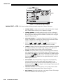
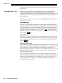
Color
Press Color to adjust the color saturation level, i.e. the amount of color in a video
image. Lower settings produce less saturated colors — a setting of “0” produces a
DLV1280 DX User’s Manual
3-7
OPERATION
black and white image, for example. If the color level is too high, colors will be
and
until the desired color saturation
overpowering and unrealistic. Use
level is displayed. The Color key has no effect when the ADP option is installed.
Tint
Detail
Cont
Bright
Vol
Proj
Tint
Press Tint to adjust the red/green color hue for true color reproduction of NTSC video
or HDTV signals. For best results, adjust tint while displaying an external test pattern
and
— otherwise, it is recommended that tint remain at its default setting. Use
until the desired tint is displayed.
Detail
Press Detail to adjust the sharpness of a video image (it is of limited use for nonvideo). Use
and
until the display is as sharp as desired, keeping in mind
that any level of detail above 3 will also introduce a certain degree of noise in the
image. Set below 3 to filter the signal and remove noise from a noisy source.
Contrast
and
until
Press Cont to change the amount of white in your images. Use
you reach the desired level of contrast—for best results, start low and increase so that
whites remain bright but are not distorted or tinted, and that light areas do not
become white (i.e., are “crushed”). Conversely, low contrast causes dim images. See
3.6, Adjusting the Image (Image Settings subsection).
Brightness
and
Press Bright to increase or decrease the amount of black in the image. Use
until you reach the desired level of contrast—for best results, start high and
decrease so that dark areas do not become black (i.e., are “crushed”). Conversely,
overly high brightness changes black to dark gray, causing washed-out images. See
3.6, Adjusting the Image (Image Settings subsection).
Volume
This key is not functional in this projector, as there is no audio capability.
Projector
Press Proj when you want to access a specific projector within a network or if you
simply need to see if the local projector is listening. The number appearing in the
“Enter Number” window indicates which projector is currently listening to
commands, and will match the projector number that has been defined in its
Communications submenu.
The “Projector” checkbox (read-only) shows whether or not the projector physically
connected to a keypad is listening to commands from that keypad. A checkmark
means that connected projector is listening; if there is no checkmark, you are
communicating with a different projector.
To use a specific projector, enter the 3-digit number assigned to the projector you
want to use. Press Enter to select, press Exit to cancel. If you switch to a projector
other than the one you are currently using, the checkmark will be deleted.
To broadcast to multiple projectors, press Proj and then Proj again without entering a
projector number. Keypad commands will then affect all projectors present.
3-8
DLV1280 DX User’s Manual
OPERATION
NOTES: 1) The "Broadcast Keys" option in the Communications menu must be
selected for only one (any) projector in a serial network. The keypad in use must be
OFF (disabled) for the remaining projectors. See 2.10. Keypad Protocols and
Conversion, and 3.7, Configuring System Parameters.
Pixel
Position
Lens
Shutter*
Pixel
Press Pixel to access the pixel tracking and pixel phase double slidebar. Adjust pixel
tracking first: use
and
to increase or decrease the frequency of the pixel
sampling clock to correct consistency and/or aspect ration of the image. For proper
phase, use ON and OFF to increase or decrease pixel phase so that any shimmer
disappears and the image is stable throughout. See 3.6, Adjusting the Image (Size and
Position subsection) for a complete explanation of tracking and phase.
Position
Press Position to move the image using the double slidebar. At the slidebar, use
and
to move the image left or right, use ON and OFF to move the image up or
down.
Lens
Remote lens features are not available in this projector. Adjust the lens manually for
proper focus and (if applicable) zoom. Offsets can also be mechanically adjusted. See
Section 2.
Shutter (OPTIONAL)
If your projector has a mechanical lens shutter (a.k.a. douser) installed, press and
hold Shutter* for approximately 1 second to toggle the shutter closed or open with a
single key press (this also blanks the image electronically). Or quickly press and
release Shutter* and follow immediately with ON or OFF if you want to guarantee the
correct toggle (useful if you are unsure of the present status). Close the shutter
whenever you want to mute all display yet maintain access to projector functions.
Open the shutter to regain the display. With no shutter installed, Shutter* still blanks the
image electronically, but the blanking is not quite as black.
NOTES: 1) Upon power-up, the shutter is open. 2) The lamp remains on regardless
of shutter status.
Mute*
Func
Mute
Use Mute* to mute (hide) the current menu—press and hold for approximately 1
second to toggle the menu on or off with a single key press. Or quickly press and
release Mute* and follow immediately with ON or OFF if you want to guarantee the
correct toggle (useful if you are unsure of the present status).
Function Key
From presentation level, press Func followed by a 2-digit number to enable a specific
will display only red and green
color or colors in the display. For example, Func
data, Func
will display all colors data. The list of available color combinations is
shown below and also appears on the back of the IR remote keypad. Color enabling
can also be accessed through the menu system rather than these shortcuts.
DLV1280 DX User’s Manual
3-9
OPERATION
Func
Func
Func
Func
Func
Func
Func
= Red
= Green
= Blue
= Red and Green
= Green and Blue
= Red and Blue
= All colors ( Exit does the same thing)
NOTE: Once Func is pressed in presentation level, the projector will not respond to
non-numeric entry until 2 digits have been entered or until 5 seconds of inactivity
have elapsed.
Use of the Func key within the menu system is noted with the appropriate topic
elsewhere in Section 3. For example, press Func in the Channel Setup menu to enable
deletion or copying of a channel.
OSD*
OSD (On-screen display)
Press and hold OSD* for approximately 1 second to toggle menus on or off (i.e.,
visible or invisible). Or press OSD* followed immediately by ON or OFF to
guarantee the correct toggle direction (useful if you are unsure of the present status).
Note that invisible menus are fully functional.
NOTE: With OSD on, you can still mute menus, error messages, slidebars, etc. with
the appropriate setting in the Menu Preferences menu.
Help
Help
Press Help for detailed information about any current menu and highlight. Press Help
again to exit. From presentation level, press Help to access the General Help menu
consisting of Using Help, Setup, Keys, Source (Input) Selection, Status/Pwr LEDs
and Using 3D. Press Exit to leave General Help and return to presentation level.
Test
Test
Press Test to display one of the available test patterns. Press Test again to display the
next available pattern in the sequence. Test will exit after the last pattern, or press Exit
at any time to remove the current test pattern from the screen and return to
presentation level. Test patterns are also accessible from within the menu system.
NOTE: For a list of test patterns, see 3.7, Configuring System Parameters
(Communications menu).
Keypad operating settings (protocols)
The remote keypad and the optional wired keypad both store keypad operating
settings (called protocols) in memory. In some advanced applications, such as when
you want to use two separate keypads to control two projectors independently, you
may want to override the original protocol set at manufacture (which is "A or B") for
one of the keypads. See section 2.10, Keypad Protocols and Conversion for complete
instructions.
3-10
DLV1280 DX User’s Manual
OPERATION
3.4
Navigating the
Menus
Most of the controls for the projector are
accessed from within the projector’s menu
system. There are several groups of related
functions, with each group selectable from the
Main menu as shown at right. Press Menu at any
time to display the Main menu.
On the keypad, either enter the number
corresponding to the function menu you wish
for the Image Settings
to access, such as
Figure 3.4. Main Menu
keys to highlight the
menu, or use the
Enter
desired option and press
. The function
menu you selected will then appear. If you select “Auto Setup”, this will not activate
a separate function menu but rather begin an automated process of optimizing critical
display parameters such as size, position, pixel tracking, etc.
Once you have a function menu displayed, navigate in a similar manner—enter a
to move the highlight
menu option number for any numbered option, or use
Enter
and press
at the desired option. Extra long menus have a scroll bar on the right–
use the arrow keys to see the remainder of the menu. Items that are locked or do not
pertain to the current action or projector appear dimmed and cannot be selected.
NOTES: 1) If there is no signal present, all source-dependent adjustments are
disabled. 2) After 15 minutes of inactivity, the projector leaves the menu system and
returns to the presentation. 3) The Status menu is read-only.
When finished with a function menu, do one of the following:
•
Press
Exit
•
Press
Menu
to return to the previous screen
to leave the menu system and return to the presentation
On-line Help ' If at any time you are uncertain what to do next, press Help to display detailed
information about the current menu or highlighted option. A scroll bar appears on the
right-hand side of a help window if there is additional text–use the arrow keys to
scroll. Press Help again to exit.
From presentation level, press Help to access general Help Topics. Scroll as necessary
within a topic. Press Exit to return to your presentation.
DLV1280 DX User’s Manual
3-11
OPERATION
Figure 3.5. Accessing General Help Topics
At the bottom of some menus, a line of hint text also appears.
Time-outs ' Whenever the projector has left presentation level, such as when there is a slidebar,
menu, message or test pattern displayed, you have limited time in which to make a
keypad entry before the projector returns to presentation level and the graphic
disappears. These time-outs vary depending on the current display, as shown in the
following chart:
TIME-OUTS
Slidebar (from pres.)
5 seconds
Slidebar (from menu)
15 minutes
Lamp Timer Msg.
30 seconds
Channel entry
5 seconds
Other
15 minutes
The Global Icon ' In the menu system, settings that include this icon apply universally to any incoming
signal.
Using Slidebars and ' Most of the function menus allow you to change settings by using slidebars,
Other Controls
checkboxes, and pull-down lists. To select a slidebar, toggle a checkbox status, or
view a pull-down list, do one of the following within the function menu:
•
•
•
•
Enter the menu option number corresponding to the setting you wish to
change (for example, press
to select Vertical Stretch in the Size & Position
menu).
Or move the highlight to the desired parameter and press Enter .
Or move the highlight to the option desired and press
or
.
Or bypass the menus entirely and use a single key to immediately access an
adjustment during your presentation (note: applies only to options having their
own key, such as Color, Tint, Detail, Contrast, Brightness, Volume, Pixel and
Position).
Once selected, change the setting as desired (see below) and press
return to the current function menu.
Enter
to save and
Slidebars in menus - The current value for a given parameter,
such as size or vertical stretch, appears to the left of its slidebar
icon (window). This number often expresses a percentage, or it may have units
associated with it (such as pixels, degrees Kelvin, etc.), depending on the specific
or
to gradually adjust the setting up or down—both the
option. Press
number and the length of the bar change accordingly (for continuous adjustment,
3-12
DLV1280 DX User’s Manual
OPERATION
hold down the desired arrow key). Or press Enter to activate a slidebar text box for
or
to save (or
specific number entry via the keypad, then press Enter or
press Exit to cancel).
Double slidebars - In double
slidebars, such as the pixel
tracking/pixel phase double slidebar,
or
adjust the top slidebar with
as desired. When you have
finished with the top slidebar (whether
changed or not), adjust the bottom
slidebar with ON or OFF . When you
are done, press Exit to return to your presentation. For fast continuous adjustments,
hold down the desired arrow key.
“Direct” slidebars - For quick access, you can often use a slidebar (or double
slidebar) without traveling the menu system. For example, simply press Cont to
immediately display the same contrast slidebar accessed with the Contrast option in
the Image Settings menu. Direct slidebars are listed below.
LIST OF DIRECT SLIDEBARS
H-Position or V-Position
Position
Pixel Tracking or Phase
Pixel
Volume
Contrast
Cont
Brightness
Bright
Color
Color
Tint
Detail
Tint
Detail
Use the arrow keys to adjust a direct slidebar, or press Enter and enter a specific
number from the keypad , then Enter or
or
to save ( or Exit to cancel).
Exit
When you are done, press
to save and return to your presentation.
NOTES: 1) You can still adjust a direct slidebar as usual if the menu display is
turned off (see OSD* or Menu Preferences menu) — the slidebar just won’t be visible.
2) A direct slidebar disappears if it is not used within 5 seconds.
Checkboxes - Conditions are present if its adjacent checkbox contains a checkmark.
to
To toggle the checkbox, simply highlight and press Enter , or highlight and use
check and
to uncheck. For a checkbox that is
numbered, simply enter the number of the option to toggle
the checkbox.
Pull-down lists – To see a pull-down list of options available for a given parameter
labeled with a ▼, you can:
•
•
Highlight it and press Enter
Or enter the menu option number.
DLV1280 DX User’s Manual
3-13
OPERATION
Use ON or OFF keys to navigate up and down within the list (the current choice is
noted with a small '). Press Enter to choose an option from the list, if desired.
Figure 3.6. Example of Pull-Down List
Or, of you prefer to quickly scroll through a list without first pulling it down,
highlight the option and use
or
. Press Enter when the desired choice appears.
or
to jump between “pages” in an extra long pull-down
NOTES: 1) Press
list. 2) Press Exit while in a pull-down list to cancel any change.
Editing Text ' ACTIVATE THE EDIT WINDOW: To enter or edit text, highlight the desired parameter
(such as a channel name) and press Enter to activate its adjacent edit window. Any
previously entered text is displayed with its first character highlighted in a square
cursor, signifying that this character is ready for editing.
NAVIGATE WITHIN THE EDIT WINDOW: Press
to move the cursor forward or
to move the cursor backwards as desired.
EDIT A CHARACTER: To
Figure 3.7. Entering Text
edit a highlighted
and
character, use
to scroll through
the alphabet, numbers, spaces and
punctuation available. When the character
to select it—
you need appears, press
the cursor will move to the next character of
current text, if present. Note that you can
also enter a number directly from the
keypad—it will be accepted and the cursor
will move on.
ADD OR DELETE A CHARACTER OR SPACE: To
press
3-14
DLV1280 DX User’s Manual
Func
insert a space at the cursor location,
. To delete a highlighted character (or space), press Func
.
OPERATION
PRESS
press
Enter
Enter
WHEN FINISHED: To
accept the edits and move out of the edit window,
.
NOTE: Press
text.
Exit
at any time to cancel changes and return to the previously-defined
Editing Numerical Values ' Enter numbers directly from the keypad in order to specify numbers representing
projectors, channels (source setups), switchers, or slots. As each digit is entered, it is
displayed and the cursor moves on. Note that channel numbers are defined with 2
digits—for example, if you enter only a single digit (like “7”) for a channel number,
the channel will automatically be defined as “07”. Use “07” to utilize this channel.
NOTES: 1) Once you enter the first digit, this digit replaces all old digits. 2) If you
press any non-numbered key, the number entered up to that point is accepted and
updated as the new value. 3) Press Exit to cancel editing of numerical values.
3.5
Using Inputs
and Channels
NOTE: See Section 2, Installation and Setup, for a full explanation of how to
connect a variety of sources to the projector.
The projector stores and automatically recalls up to 99 different channels (source
setups) for a variety of inputs. This memory feature allows you to define and
conveniently use a wide variety of customized setups rather than having to repeatedly
re-configure the projector for different presentations. Each physical source (i.e.,
input) can have several different channels associated with it.
Do I Select an Input ' INPUT - An input simply describes a physical location for an incoming signal
Or a Channel?
connection. These connections are always either on the projector itself (one of the
four inputs at the rear of the projector) or on any switcher connected to the
projector’s switcher port. Input describes the source signal according to two specific
criteria only—to which switcher it is connected and to which slot it is connected—
and is identified by a 2-digit number entered on the keypad. The first digit specifies
the switcher (0-9), the second specifies the slot (1-9). Note that the projector is
always considered “switcher #0”.
EXAMPLES:
Input
Input
= use source connected to switcher #1, slot #3
= use source connected to the projector, slot #1 (i.e.,
Input1
)
You can switch to an input in either one of two ways. Pressing the appropriate direct
key — Input1 , Input2 , Input3 , or Input4 — is a quick and seamless way to display from one
of the four inputs connected at the rear of the projector. Or, if your projector has a
switcher connected to it at the SWITCHER port, press the general Input key and enter
DLV1280 DX User’s Manual
3-15
OPERATION
the 2-digit number representing the switcher and slot location for the desired signal
(note there is no on-screen feedback for entering the numbers).
Regardless of which method you use to select a source/input, the image will be
displayed according to the following:
If it is the first time you have used the source/input (or if you used the input but did
not define a channel by adjusting anything ), the projector will recognize the new
input signal based on its frequencies and polarities, and will automatically display an
image according to default settings for such a signal. Note that a graphic source will
resize into a full-screen image, whereas video or HDTV sources will resize only as
much as possible while maintaining their aspect ratio.
If you used the source once before and changed a display parameter such as
contrast, V-Position etc., then a channel was automatically created and still exists in
projector memory (see below). Using an Input key will automatically recall this
channel—and all its setup parameters—and update the display accordingly.
If more than one channel exists for the input, the image will be displayed according
to the setup parameters for the first channel with matching characteristics.
CHANNEL - A
channel is a collection of measurements, locations and settings that
tailor a display to your specific needs. Since source types and applications can vary
greatly, you will likely want to adjust and define a wide variety of parameters, such
as brightness, contrast, tint, size, etc., in order to customize and optimize the display
coming from a particular source. For example, the display settings you choose for a
VCR source may be very different from those you choose for a high resolution
computer source, or one signal may simply vary from another signal used earlier
through the same input location. Once you have adjusted a display parameter, such as
pixel tracking or contrast, all current settings are collectively stored in the projector's
. You can have numerous distinct
memory as a unique 2-digit channel, such as
channels available for the same input, any of which can be selected by using the Chan
key on the keypad followed by the 2-digit
channel number.
NOTE: The Chan key may display a channel
list or not, depending on what you have
defined within the Menu Preferences menu
(see Menu Preferences later in this section).
Shown at right is a sample channel list
available from Chan .
In order to use channels ( Chan on the keypad),
you must first create them. See below.
Creating a New ' To use a new source with the projector, a new channel must be added to projector
Channel
memory so that the projector will respond properly to an input signal from that
— AUTOMATIC —
source in the future. A new channel can be created automatically, as described here,
or it can be copied from an existing channel and then edited as necessary (see
Copying or Deleting Channels later in this section).
When you select a direct input (press Input or Input1 , Input2 , Input3 or Input4 ), the existing
channels in the projector are searched for matching input and signal parameters. If no
match to the incoming input signal is found in the currently defined channels, a new
3-16
DLV1280 DX User’s Manual
OPERATION
channel is temporarily created based on factory-defined defaults for this signal. The
channel number assigned to this channel is the lowest available number from 01-99.
NOTES: 1) An automatic channel will be discarded unless one or more of its
parameters are changed, and will not appear in the Channel List (see below). 2) If
two channels have the same distinguishing source characteristics except for the
reversal of sync connectors (i.e., H-sync and V-sync, are switched), they are still
defined as distinct channels. 3) You cannot define a new channel without a signal
present.
If the incoming signal does match an existing channel, the image will be set up and
displayed as usual according to the parameters currently defined for that channel.
USING A CHANNEL: You
can normally select a channel at any time by pressing
(see right). If you want to
prevent a channel from
appearing in this list, you
must edit the channel as
described in Channel Edit
later in this section. Such a
channel can still be
selected by entering its
number as shown at right.
Chan
NOTE: 1) The current channel is highlighted upon entering the Channel List, or, if
this channel is not displayed in the list, the first channel in the list is highlighted. 2)
Channels created automatically do not appear in the Channel List unless a
parameter has been changed.
What Channels ' All available channels are listed in the Channel Setup menu, which describes how
Are Defined So Far?
each channel can be accessed and which serves as the gateway for editing, copying
and deleting channels.
From the presentation
level press Menu to
display the Main menu.
To display the Channel
Setup menu, press , or
move the highlight to the
Channel Setup option
and press Enter . The
Channel Setup menu will
appear (see sample at
right), with the active
channel highlighted.
Figure 3.8. All Channels Appear in the
Channel Setup Menu
WHAT APPEARS IN THE CHANNEL SETUP MENU? This menu
lists all channels defined
so far and indicates how they are connected to the projector. The far left column
contains current channel numbers defined. The values in the far right columns
indicate horizontal and vertical frequencies—if a name has been defined for this
channel, it appears here instead. Remaining columns contain details pertaining to
each channel setup, such as its switcher number, slot location, a variety of icons
indicating access to each channel, and an abbreviated description of each signal type.
See Editing a Channel Setup for details.
DLV1280 DX User’s Manual
3-17
OPERATION
NOTE: If you have more than a handful of channels, use
and
remaining channels not visible in the initial display of channels.
to see the
SIGNAL TYPE — Either
channel list, whether the Chan key list or the Channel Setup
menu, identifies signal types in a shortened form as defined below. These descriptors
indicate what signal information the projector used to identify a match for a given
channel, and are preceded by either an “i” (interlaced signal) or “p” (progressive
signal). See Table 3.1.
Table 3.1. Abbreviations for Signal Type
Abbrev.
4WH
4WV
SG
SR
5W
5WR
SVid
CVid
3LH
3LV
3LG
E3LH
E3LV
E3G
Dig
Signal Type
Composite (4 wire) on HC input
Composite (4 wire) on V input
Sync-on-green
Sync-on-red
Separate H,V
Separate H,V swapped
S-Vid
Composite Video
Tri-Level on HC input
Tri-Level on V input
Tri-Level on green
European Tri-Level on HC input
European Tri-Level on V input
European Tri-Level on green
Digital
FUNCTIONS WITHIN THE CHANNEL SETUP MENU — To
copy, delete or edit any of the
channels listed in the Channel Setup menu, highlight the desired channel and do one
of two things:
•
•
Press Func if you want to copy the selected channel or delete this or other
channels. See Copying or Deleting a Channel below.
Press Enter if you want to edit channel setups (i.e., non-image related
parameters) for the selected channel. See Editing a Channel Setup,
below.
Copying or ' TO COPY A CHANNEL, highlight the desired channel in the Channel Setup menu, then
Deleting Channels
press Func to go to the Channel Copy/Delete submenu. Select “Copy” and press
Enter —a new channel will be created. It is identical to original, which still remains,
but it is identified with the next available number from 01-99. If you change your
mind and do not want to copy the current channel, press Exit to cancel and return to
the previous menu. Copying channels is a quick method for creating numerous
channels, each of which can then be edited and adjusted for a variety of presentations
in the future.
3-18
DLV1280 DX User’s Manual
OPERATION
Figure 3.9. Copying A Channel
TO DELETE A CHANNEL,
highlight the desired channel in the Channel Setup menu,
then press Func to activate the Channel Copy/Delete submenu. Select “Delete” and
press Enter —a confirmation window will appear to make sure that you really want to
delete this channel.
Figure 3.10. Deleting a Channel
TO DELETE MULTIPLE CHANNELS,
highlight any channel in the Channel Setup menu
and press Func to go to the Channel Copy/Delete submenu. Select “Delete Unlocked
Only” and press Enter to delete all unlocked channels. Or select “Delete All Channels”
to delete all channels, even those that are locked. In either case, the current channel
will remain but will be redefined from projector defaults.
NOTE: For any deletion, a confirmation box appears to make sure that you really
want to delete. Select “Cancel” (default) if you don’t want to delete after all.
Editing a Channel Setup ' The basic setups that describe how and where a channel can be accessed are listed in
the Channel Setup menu. These channel setups can be edited at any time in the
Channel Edit submenu.
CHANNEL EDIT — STEP 1 From the presentation level press Menu to display the main menu. To display the
Channel Setup menu, press , or move the highlight to the Channel Setup option
and press Enter . The Channel Setup menu will appear.
CHANNEL EDIT — STEP 2 To edit parameters shown in the Channel Setup menu, select the relevant channel and press
Enter . The Channel Edit menu will appear similar to the sample shown in Figure 3.11.
DLV1280 DX User’s Manual
3-19
OPERATION
Figure 3.11. Channel Edit Menu ( SAMPLE)
CHANNEL EDIT — STEP 3 If desired, edit the following channel setups in the Channel Edit menu:
3-20
DLV1280 DX User’s Manual
•
alpha-numeric label can be defined and/or changed
here. Channel names can be up to 12 characters in length.
•
CHANNEL NUMBER: A channel number from 01 to 99 can be changed
here. NOTE: If you enter a channel number that already exists, a dialog
message appears indicating that this number is already in use–assign a
different channel number.
•
SWITCHER NUMBER: “0”
represents the projector itself. Or, if the input
source is connected to a switcher, the default will be the lowest switcher
number available (from 1-9)–change here as desired.
•
SLOT:
1 ( Input1 ), 2 ( Input2 ), 3 ( Input3 ), or 4 ( Input4 ) for projector inputs, or
current slot number (1-9) if the source is connected to a switcher.
•
LOCKED: If
•
IN MENU: If
•
AUTO SOURCE: If checked, (default), the projector can automatically
locate this channel when an incoming input signal matches. If not
checked, the projector can locate the selected channel only when it is
directly selected via Chan on the keypad—and a change in input signal will
not result in a channel change.
•
PREVIOUS CHANNEL:
•
NEXT CHANNEL: Select this option to see or change Channel Edit settings
for the next channel in the Channel Setup list.
CHANNEL NAME: An
checked, all of the image settings for this channel are disabled.
If unchecked (default), all available image settings can be adjusted as
desired. You cannot use Auto Setup with a locked channel.
checked (default, except for automatically defined channels
with unchanged parameters), this defined channel will then appear in the
list available when Chan key is pressed. If unchecked, the channel must be
accessed via Chan on the keypad or via the Auto Source function. NOTE:
On-screen display of the channel list is an option that must be set in the
Menu Preferences menu.
Select this option to see or change Channel Edit
settings for the previous channel in the Channel Setup list.
OPERATION
3.6
Adjusting the
Image
Most options for image adjustments can be accessed through two menus: Size and
) and Image Settings ( Menu
), both of which are listed in the Main
Position ( Menu
menu. While in either of these two menus, you can change settings affecting the
image from the current channel by working with the appropriate slidebars,
checkboxes and pull-down lists. Exit will always return to the previous menu (or to
the presentation, if from the Main menu) and accept any changes you may have
made. Or you may prefer to begin with an automated setup in which the projector
quickly defines certain parameters for you—select Auto Setup from the Main menu.
These settings can then be fine-tuned in Size and Position and Image Settings at any
time.
From your presentation, you can access any of the individual options in these menus
by pressing Menu followed by the appropriate two-digit number representing their
to quickly access the
location in the menu system. For example, press Menu
“Color Setup” option in the Image Settings menu.
Note that for certain options, you may prefer to use a “direct key” from presentation
level to go directly to a particular option rather than traveling through the menu
system at all (note: this is not available for all display parameters). For example,
press Cont to access the “contrast” slidebar immediately. Press Exit to return to your
presentation.
NOTES: 1) To hide the “direct” slidebars only, make sure the Display Slidebars
option in the Menu Preferences menu is unchecked. 2) To hide the entire menu
system from view, toggle the on-screen display OFF: press and hold the OSD* key.
Auto Setup ' If you want the projector to quickly set up the image for you, select “Auto Setup”
from the Main menu. A confirmation box will ask if you really want to continue, in
which case display parameters listed in the Table below will be set for you. An “Auto
Setup” can save time in setting up an image, and you can also make further
adjustments as desired. You must have an unlocked channel present to use Auto Setup.
Table 3.2. Auto Setup
What an “Auto Setup” Does
OPTIMIZES:
SETS TO DEFAULT:
Pixel Tracking
Pixel Phase
Size
Contrast & Brightness
Vertical Stretch
Auto Input Level (off)
Position
Blanking
Input Levels (if analog source)
Detail (if video source)
Filter
Luma Delay
DLV1280 DX User’s Manual
3-21
OPERATION
Image Size and Position ' The Size and Position menu allows you to
increase or decrease the size of your
image, change its proportion (aspect
ratio), move the image to a specific area
of the screen, and refine other related
parameters. Use Size and Position
controls to match the image precisely to
the screen size and aspect ratio needed for
your application.
Refer to "Using Slidebars and Other
Controls" (earlier in this section) if you
need help using any of the following
slidebars or pull-down lists to alter your
image. Changes made to the Size and
Position menu are applied immediately
and are saved when you exit the menu
(press Exit or Menu ).
Figure 3.12. Size and Position Menu
Resize Presets
Use Resize Presets to quickly
display an image in its native
resolution (including
anamorphic) or to
automatically resize an image
to closely fit the screen. The
value for Size, Position and
Blanking parameters
(described later) will, in turn,
change as necessary without
your having to set them
Figure 3.13. Resize Presets Choices
manually. Resizing options
for non-tiled applications are explained in detail below.
WHAT IS THE PROJECTOR’S DEFAULT? When displaying a new source, by default
your image will fill the screen as fully as possible for the type of source present. See
Select “Default” below.
WHEN “CUSTOM” APPEARS: The “Custom” descriptor automatically appears in the
Size and Position menu when any of the values for Size, Vertical Stretch, H-Position,
V-Position or Blanking do not correspond to those for a preset. It is not an option in
the Resize Presets pull-down list.
• SELECT “DEFAULT” (default) for most images. This option will center and display
your image as large as possible for the present source as described below:
9 A graphic image will resize to fill the screen, regardless of its original
aspect ratio. For example, 1024 x 768 becomes 1280 x 1024.
9 A video image will resize to fill the screen while maintaining its aspect
ratio (assumed to be 4:3).
3-22
DLV1280 DX User’s Manual
OPERATION
9 An HDTV wide-screen (16:9) image will resize to fill the screen
horizontally in a 16:9 aspect ratio (i.e., there will be black borders at top
and bottom, commonly called “letterboxed”).
9 A non-HDTV anamorphic (16:9) image, common on DVDs, will be
stretched vertically.
So with the exception of HDTV (16:9), the “Default” setting produces an aspect
ratio that is either almost or exactly 5:4. See below.
• SELECT “NO RESIZING” to display the image in its native resolution, which may be
smaller or larger than 1280 x 1024 (the projector’s native resolution). All Size,
Vertical Stretch, H-Position, V-Position or Blanking values will change
accordingly. For example, for a source with a native resolution of 800 x 600, “No
Resizing” will center a small image within a black border. Conversely, an HDTV
image is wider than 1280 and will be cropped on the sides or, in the case of
“1080i” HDTV, cropped at top and bottom too. With “No Resizing”, signals with
non-square pixels, such as video connected to INPUT 3 or INPUT 4, produce
distorted images that are too tall or too wide. See below.
• SELECT “FULL SCREEN” to use all pixels (1280 x 1024)
for displaying the image, regardless of source or
original aspect ratio. See right.
• Select “FULL WIDTH” to fill the display from left-toright. Depending on the source, this may create top
and bottom borders. See right.
DLV1280 DX User’s Manual
3-23
OPERATION
• Select “FULL HEIGHT” to fill the display from top-tobottom. Depending on the source, this may create
side borders. See right.
• Select “ANAMORPHIC” to display an entire nonHDTV “wide screen” (anamorphic) image in its native
16:9 aspect ratio. Known as letterbox, the image will fill
the screen from left-to-right, but will not use all vertical
pixels available (top and bottom will be black). If you
do not choose “Anamorphic” when a non-HDTV
anamorphic image is present, the default image will be
stretched vertically, characterized by obvious distortion
and “thin people”.
NOTE: Use “Anamorphic” for regaining a 16:9 display of non-HDTV
anamorphic sources only (typically found on some DVDs, for example). For
HDTV, the “Default” setting will produce the same result.
• All TILED resizing choices are selectable only if you have defined a tiled group of
projectors in the Tiling Setup submenu. See 3.10, Using Multiple Projectors.
Size
Size controls both the image width and height in tandem, maintaining the original
aspect ratio (proportion) of data from the incoming signal.
Vertical Stretch
Vertical stretch adjusts the height the image while keeping the width constant. Use
Vertical Stretch to display data from the incoming signal in a different aspect ratio.
Pixel Track
(SHORT CUT: Press
Pixel
and adjust the top slidebar.)
Pixel tracking adjusts the frequency of the pixel sampling clock, indicated by the
number of pixels per line, so that all pixels generated by a particular source are
sampled. Proper pixel tracking ensures that the image quality–whether good or poor–
is consistent across the screen, that it is the correct aspect ratio, and that pixel phase
can be optimized (below).
NOTE: By default, the projector will sample at the correct frequency for most sources.
Pixel tracking is adjusted most effectively using a good test pattern, such as a smooth
gray consisting of a clear pattern of tiny black and white dots, or a similar “half on,
half off” graphic image, such as the Windows shutdown screen. Steady flickering or
several soft vertical stripes or bands across the entire image indicates poor pixel
tracking. Adjust the slidebar until the stripes broaden to the point where one large
stripe fills the image. Again, the image may still exhibit some noise. See Pixel Phase.
3-24
DLV1280 DX User’s Manual
OPERATION
Pixel Phase
(SHORT CUT: Press
Pixel
and adjust the bottom slidebar.)
Pixel phase adjusts the phase of the pixel sampling clock relative to the incoming
signal. It is used primarily for adjusting RGB inputs.
NOTE: Adjust pixel phase after pixel tracking is properly set.
Adjust pixel phase when the image (usually from an RGB source) shows shimmer or
“noise”. Pixel phase adjustment is done most effectively from within a proper test
pattern, such as a smooth gray consisting of a clear pattern of tiny black and white
dots, or a similar graphic image, such as the Windows shutdown screen. Adjust until
the image is stable and each dot is clearly defined. Using the numbers on the slidebar
as a guide, you will notice that you can actually stabilize the image at more than one
point—i.e., you may find that the image appearance at "11" is identical to the image
appearance at "38", thus you can select either setting.
If, after properly adjusting both pixel tracking and phase, the image still appears
“noisy”, adjust Filter as described below.
Filter
This option applies a low pass filter to the input signal. Filter removes high
frequencies which can improve pixel phase noise but which also reduces signal
bandwidth. Note that most signals will not require any filter adjustment—use the
filter option only if standard pixel tracking and phase adjustments do not adequately
clear up a “noisy” signal. For best results:
1. Optimize Pixel Tracking and jot down the
value.
2. Optimize Pixel Phase
3. If the image is still too noisy, return to Pixel
Tracking and “mis-adjust” so that 2 vertical
bands of noise appear, separated by a good
center band. See right.
4. Adjust Filter to maximize the width of the good
area. See right.
5. Return Pixel Tracking to its correct setting from
Step 1.
6. Readjust Phase.
NOTE: “Filter” affects only the current signal.
H-Position
(SHORT CUT: Press
Position
and adjust the top slidebar.)
This option moves image right or left.
NOTE: The value shown represents where the approximate center of the image lies in
relation to the total number of pixels available horizontally. This varies widely
according to the signal—watch the image while adjusting.
DLV1280 DX User’s Manual
3-25
OPERATION
V-Position
(SHORT CUT: Press
Position
and adjust the bottom slidebar.)
This option moves the image up or down.
NOTE: The value shown represents where the approximate center of the image lies in
relation to the total number of pixels available vertically. This varies widely
according to the signal—watch the image while adjusting.
Lens Control
Not in this projector.
Blanking: Top, Bottom, Left or Right
This submenu blanks (turns to black) the top, bottom,
left, or right edge of the image so that any unwanted
information is cropped from view. For example, when
displaying native size video you may want to blank out
a few of the top lines.
PLL Loop Gain
This control changes the relative offset to the default gain. The default PLL (Phase
Lock Loop) Gain setting of 10 is set automatically with a Pixel Tracking adjustment
and is correct in most cases. In rare instances, such as if your image exhibits tearing
or “flag-waving”, increase the PLL loop gain setting as necessary. Or, if your image
is unstable and “breaks up”, this may indicate that the PLL loop gain setting is either
too high or too low. PLL Loop Gain affects the current channel only.
Keystone
Not available in this projector.
Plug & Display (EDID)
NOTE: Requires optional DVI Input Module. Disabled for all other inputs.
By default, the Plug & Display option detects an incoming digital flat panel video
signal and displays it in the native resolution of your
projector. If you have additional daisy-chained projectors,
they will display in this resolution as well. If you want to
use a different resolution (for example, your graphics card
may not support the current resolution), select a different
Plug & Play setting from the list.
Tiling Setup
See 3.10, Using Multiple Projectors (Tiling Setup section).
3-26
DLV1280 DX User’s Manual
OPERATION
Image Settings ' Use any of the following slidebars,
pull-down lists or the checkbox to
alter your image. Refer to "Using
Slidebars and Other Controls" (earlier
in this section) if you need help in
selecting options and adjustments.
Changes made to the Image Settings
menu are applied immediately and are
saved when you exit the menu (press
Exit or Menu ).
Contrast
(SHORT CUT: Press
slidebar.)
Cont
and adjust the
“Contrast” increases or decreases the
perceived difference between light
and dark areas of your image (0-100).
If contrast is set too high, the light
parts of the image lose detail and
clarity. If set too low, the light areas
Figure 3.14. Image Settings Menu
will not be as bright as they could be
and the image will be dim. Start low
and increase so that whites remain bright but are not distorted or tinted, and that light
areas do not become white (i.e., are “crushed”). For best results, keep close to 50.
NOTE: If environment lighting changes, it may be necessary to re-adjust both
options.
Brightness
(SHORT CUT: Press
Bright
and adjust the slidebar.)
“Brightness” increases or decreases the amount of black in the image (0-100). Start
high and decrease so that dark areas do not become black (i.e., are “crushed”).
Conversely, high brightness changes black to dark gray, causing washed-out images.
For best results, keep close to 50.
Pixel Phase
(SHORT CUT:
Press
Pixel
and adjust the slidebar.)
See description in Size and Position section, above.
Detail
(SHORT CUT: Press
and adjust the slidebar.)
”Detail” adjusts the sharpness of a video image. Use
and
until the display
is as sharp as desired, keeping in mind that any increase in detail above 3 (default)
will also introduce a certain degree of noise in the image. Set below 3 to filter the
signal and remove noise from a noisy source. Keep at 3 to apply no detail.
DLV1280 DX User’s Manual
3-27
OPERATION
Color Space
This option determines how the color components of an input signal are decoded for
accurate color in the display. Selecting a color space option is useful only for analog
signals connected to INPUT 1 or INPUT 2. Although the color space for such a signal is
automatically determined by the projector, in some circumstances you may wish to
override this and manually set a different color space.
NOTE: For digital signals or for signals connected to INPUT 3 or INPUT 4, the color
space function is entirely automatic and the pull-down list disabled.
The current color space appears in the Image Settings menu. Press
different option:
•
•
•
to select a
Select RGB unless you are using component video at INPUT 1 or 2.
Select YPbPr (Video) with a standard definition televised signal (SDTV)
Select YPbPr (HDTV) with a high definition televised signal (HDTV).
NOTE: When certain RGB signals are first connected, the projector may not initially
recognize them as RGB and will incorrectly decode their color information as YPbPr
(video). These signals can include:
•
•
•
RGB signals in NTSC, PAL, SECAM frequency ranges
Scan-doubled sync-on-green
Scan-quadrupled sync-on-green
For these signals, change the Color Space to RGB, then define a new channel for
future use.
Color Setup
Select this submenu to work with
aspects of color—adjust for
saturation and overall hue in video
signals, or adjust gamma or
temperature in any signal.
COLOR —
“Color” adjusts the
color saturation level or the
amount of color in a video image. When set to “0’ the image appears black and
white, and when set too high the colors appear overpowering and unrealistic. Use
and
to adjust “Color” until the desired saturation level is displayed. For a
shortcut to “Color” slidebar, press Color at any time.
TINT — “Tint” adjusts color hue to obtain true color reproduction of NTSC video
signals or HDTV signals. Use
and
until the desired balance or red-to-green
is displayed in your image. It is best to adjust tint while displaying an external test
pattern—otherwise, it is recommended that tint remain at its default setting. For a
shortcut to “Tint” slidebar, press Tint at any time.
3-28
DLV1280 DX User’s Manual
OPERATION
SELECT COLOR TEMP —
“Select Color Temp” applies either a
preset color temperature (3200K, 5400K, 6500K or 9300K) or
any previously “User” defined color temperature. Color
temperatures are measured in degrees Kelvin and represent the
“coloration” (reddish or bluish) of the whites displayed by the
projector—the lower the temperature, the more reddish the
whites; the higher the temperature, the more bluish the whites.
NOTE: The custom temperatures “User” or “Interpolated
Color” can be defined in the Color Temperature Setup menu.
Until defined, these custom choices all default to 6500K. See 3.7, Configuring
System Parameters.
INTERPOLATED COLOR — Use this
option if you need a specific color temperature
that lies somewhere between one preset color temperature and another. Adjust the
slidebar to define a new temperature which will be interpolated from the neighboring
presets (for example, 7841 is interpolated from 6500 and 9300). This slidebar is
disabled unless you have a source connected and have selected “Interpolated Color”
in the “Select Color Temp” pull-down list.
GAMMA — NOTE:
Gamma does not normally require adjustment and is intended for
experienced users only.
The "Gamma" option affects the shape of the curve determining
what gray shades are available for a given amount of signal
input between minimum (black) and maximum (white).
Different curves can improve performance for certain kinds of
source input and applications. Generally the best gamma curve
is one that produces maximum contrast, brightness and color
performance for the current signal and ambient lighting
conditions.
DEFAULT (default) –
This setting provides good black levels and high contrast
under optimum viewing conditions for virtually all types of images, including
video, HDTV and computer graphics. “Default” is the only gamma setting
available when using the Adjust Primary Colors (CDS) feature—see 3.10, Using
Multiple Projectors.
ENHANCED – This setting elevates middle gray levels compared to “Default”, and
provides a more gradual rolled-off transition to maximum white. Together, these
differences can improve the appearance of many kinds of images.
HIGH AMBIENT – This setting elevates low gray levels compared to the “Default”
and “Enhanced” settings. In high ambient light conditions, details can be seen in
the dark parts of an image that would otherwise be difficult to perceive.
PAL/SECAM – This setting results in a darker image with higher contrast. The
gamma curve more closely matches the official standard for PAL and SECAM
video signals.
LINEAR – This setting is a straight, linear transition from black to white. For
normal source signals, it results in a picture of low contrast with highly elevated
low- and mid- level grays. It should be used only with sources that have their
own pre-applied gamma control.
DLV1280 DX User’s Manual
3-29
OPERATION
COLOR TEMPERATURE SETUP —
Use the Color Temperature Setup submenu to
apply, alter, add, or copy a color temperature, or if you want to use an unaltered
factory default color temperature.. This menu is duplicated in other locations.
By default, the projector can utilize any of four calibrated factory-set color
temperatures: 3200, 5400, 6500 or 9300 (expressed in degrees Kelvin). For most
applications, these temperatures will display accurate and realistic colors from a
variety of sources. They can be selected at any time from the “Select Color Temp”
list in the Color Setup submenu.
However, if you require extra color temperatures, you can also add up to five custom
color temperatures—four “User” and one “Interpolated Color”—by defining them
within the Color Temperature Setup menu (each defaults to 6500K until then). Any
“User” or “Interpolated Color” temperature created here is immediately applied, or it
can be selected at any time from the Color Setup menu as usual, regardless of your
source or channel. Use of the Color Temperature Setup menu is described below.
NOTE: For best results, use an internal grayscale test pattern when working with
color temperature.
Figure 3.15. Color Temperature Setup Menu
SELECT COLOR TEMP – See Figure 3.15. Upon opening the Color Temperature
Setup menu, the current temperature appears as the top option. You can change to
a different color temperature here as desired, just as in the Image Settings menu.
Note that selecting a “User” color temperature, enables the “White Level”
options in the Color Temperature Setup—adjust as desired to define or change a
“User” color temperature (see “White Levels”, below). Likewise, selecting
“Interpolated Color” here activates the “Interpolated Color” slidebar for choosing
a new interpolated color temperature for a connected source.
INTERPOLATED COLOR – Select this option if you need a specific color
temperature that lies somewhere between one preset color temperature and
another. Adjust the slidebar to define a new temperature which will be
interpolated from the neighboring presets (for example, 7841 is interpolated from
6500 and 9300). It can be used any time and appears as a 4-digit temperature
when in use. NOTE: This option is disabled unless you have a source connected
and have selected “Interpolated Color” in the “Select Color Temp” pull-down
list.
3-30
DLV1280 DX User’s Manual
OPERATION
WHITE LEVELS –These
3 controls are adjustable only if a “User” choice is
selected (in which case “User 1, 2, 3 or 4” appears at the top of the Color
Temperature Setup menu). Their current values are shown for the active color
temperature. Changing a white level here changes the drive (contrast) for that
color, essentially creating a new color temperature that is “warmer” or “cooler”
etc. For maximum overall brightness, always keep at least one white level at
100. When you are satisfied with the new “User” temperature, it can be used
immediately upon exit or it can be selected from either the Image Settings menu
or the Color Temperature Setup menu as usual. You can re-define a “User” color
temperature at any time using the Color Temperature Setup menu.
COLOR ENABLE – Select which color or colors you want to see, useful while
working with color temperature white levels.
COPY FROM –
Use this option to replace the currently selected “User” color
temperature setup with that of another. This function can be particularly useful as
a starting point for a new “User” color, or for accessing an unaltered factory
default. It is disabled for all color temperatures except “User”. See Figure 3.16.
Figure 3.16. “Copy From”
To create a starting point: To set a starting point for a new custom user color
temperature, select a user temperature, then highlight “Copy From” and select a
temperature similar to what you want. Adjust white levels from there as desired.
To use a factory default: The preset
color temperature setups (3200K,
5400K, 6500K and 9300K) can be
altered from within the passwordprotected Service menu only—note that
although such an alteration changes the
setup and appearance for a preset, it
does not change its name. If you suspect
that you are using a preset temperature
that has been altered and you want
instead to use the original factorycalibrated color temperature without
clearing the entire projector memory,
you can use the “Copy From” option in
the Color Temperature Setup menu to set
Figure 3.17. Presets and
“Factory” Presets
DLV1280 DX User’s Manual
3-31
OPERATION
up a “User” temperature with settings from a permanent factory preset:
1. Select the “User” color temperature you wish to update at the top of the Color
Temperature Setup menu, such as “User 2”.
2. From the “Copy From” list, select the matching temperature labeled “Factory”
(such as “Factory 5400K”). These are the calibrated color temperatures set at
manufacture—they remain intact for the life of the projector.
3. The setups for the “User” color temperature you selected at the top of the
Color Temperature Setup menu will now be updated/replaced by those for the
permanent factory calibrated temperature you selected in the “Copy From”
list. Again, a “User” temperature can be altered at any time, if desired.
Video Options
Not applicable with graphics sources.
VIDEO STANDARD — The
projector
automatically detects the video standard
present and displays the name of this
to view or
standard here. Press
select a different video standard from a
complete list available to the projector
(some will appear disabled, depending on the current incoming signal). Selecting a
specific standard forces the projector to process the signal according to this standard.
NOTE: This option should remain set at “Auto” for all instances EXCEPT: 1) a poor
quality input signal or 2) a black-and-white video signal. In order to detect and
display such signals, select the relevant standard.
INPUT VIDEO BLACK — This control compensates for incoming elevated black levels–
called “setup”–that are present in certain video signals, and ensures that blacks on
screen are neither crushed (i.e., with dark gray appearing black) nor excessively
elevated (i.e., with black appearing dark gray). By default, the projector automatically
determines the correct setting according to the type of incoming video signal:
•
•
0 IRE –
For DVD output with “enhanced black”, SECAM, most PAL
standards, and Japanese NTSC.
7.5 IRE – For most NTSC video signals.
For some types of video, you can override the setting. The control is disabled for other
types of video (and all graphics sources). Generally, if black appears crushed when
brightness = 50, choose “0 IRE”. If black appears excessively elevated, use “7.5 IRE”.
VCR – This
control determines to what degree the projector tolerates signal
disturbances. The correct setting is automatically determined and set according to the
type of incoming source signal–for instance, there should be a checkmark for all
VCR sources. The VCR option may require a change from its auto setting in very
rare circumstances only, such as if you are having difficulty switching between two
unusual and almost identical VGA computer sources. Otherwise, it is not necessary
to change this option.
3-32
DLV1280 DX User’s Manual
OPERATION
VIDEO TERMINATION — Enter a
checkmark
to terminate the video inputs 3 and 4 (75
S). The input should be terminated unless
the signal loops through (continues) to
another projector or display device, in
which case only the last projector in the
chain should be terminated.
ENABLE DECODER AGC – The “automatic gain control” affects decoded video images
only. Enter a checkmark (default) for most decoded video sources—this activates the
AGC circuit to ensure properly bright images. Delete the checkmark if a decoded
video image exhibits strange color artifacts such as stripes in highly saturated colors,
indicating an incompatibility between this source and the AGC.
DECODER LUMA DELAY – This control affects any incoming composite or S-video
signal, delaying the luma signal (intensity) in relation to the chroma (color). In the
image, increasing the luma delay will move luma (seen as a shadow where colors
overlap) to the right slightly, with colors remaining in place. Decreasing this delay
will move the shadow slightly to the left. If necessary for your current source, adjust
so that no shadows occur with adjacent colors.
Input Levels
NOTES: 1) It is recommended that only experienced users use the Input Levels
submenu—the projector automatically optimizes input levels for all but the most
unusual of sources. 2) Before attempting an input level adjustment, check that overall
contrast and brightness settings are near 50 and that color temperature is properly
set up on an internal grayscale test pattern. 3) There must be at least one white pixel
present in the image for proper “Auto Input Level” function. Leave this control off.
Good RGB or input
levels—that is, the
drives and blacklevels
for each of the three
colors, red, green and
blue—ensure that
images from analog
sources other than
decoded video have
maximum contrast
without crushing black
or white. By default
Figure 3.18. Input Levels Submenu
(and in an “Auto Setup”
from the Main menu), the projector automatically determines the best input levels by
monitoring image content and adjusting the controls appropriately—further
adjustment is typically not required to obtain proper blacks or whites. NOTE: This
automatic adjustment requires at least 1 white pixel in the image. Without a white
pixel, input levels may produce skewed colors, particularly in non-video images.
However, for a very unusual source exhibiting overly high blacklevels (most often
caused by a noisy source that causes blacklevel spikes), an experienced user may
prefer to use the Input Levels menu (see Figure 3.18). These adjustments, which are
actually a calibration process to compensate for differences in sources and cabling,
enables an experienced user to perfect the source image input levels. Note that Input
DLV1280 DX User’s Manual
3-33
OPERATION
Levels are of limited use with digital signals, but offer some ability to tweak poorly
mastered source materials.
AUTO INPUT LEVEL – Keep off for virtually all sources (default). Temporarily enter a
checkmark only if you are an experienced user and you have an unusual source that
you feel needs further color temperature and/or input level adjustment. After entering
a checkmark, wait for the six values to stabilize, then delete the checkmark and exit.
BLACKLEVELS AND DRIVES - To check your
image and adjust these controls:
1. Make sure overall Contrast and Brightness are both set to near 50.
NOTE: Not required for “Auto” adjustment.
• Cont = 50 (approx.)
•
= 50 (approx.)
2. Check the color temperature setup using an internal grayscale test
pattern, adjusting as desired to obtain a neutral grayscale. NOTE: Not
required for “Auto” adjustment.
3. Make sure you are using an analog source not connected to INPUT 3 or
INPUT 4, as Input Levels are not applicable for digital sources or sources
going through the decoder. A grayscale is recommended.
4. If the blacks and/or whites appear OK, input levels do not need
adjustment. If black levels are too high (and/or whites are too low, which
is rare), you likely have a noisy source that is producing skewed input
levels. Continue with Step 5.
5. Temporarily enable “Auto” in the Input Levels submenu. Wait for all 6
values to stabilize. Alternatively, do not use “Auto”—reduce blacklevels
manually instead. Judge by eye and change one or more of the six levels
as necessary to obtain proper blacks and whites. You may want to see
only a certain color while adjusting—use the “Color Enable” option
(described below).
6. Delete the “Auto” checkmark and leave the Input Levels menu.
IMPORTANT: Do not use Input Levels to adjust color temperature. This will
distort Contrast and Brightness functions as well as color temperature.
CLAMP TIP –
This option (full name sync tip clamping) can brighten the image
produced from certain high resolution, high frequency graphic sources. Enter a
checkmark if the image appears unusually dim, if there are horizontal streaks across the
image, or if there is significant color drift. Delete the checkmark if the image is either
sufficiently bright or overly bright.
NOTE: The sync tip clamping option is not used for video sources or any RGB source
with sync information on the video (e.g., sync-on-green).
COLOR ENABLE – Select which color or colors you want to see, useful while working
with color temperature white levels or input levels.
NOTES: 1) Input levels apply for the current source only, but for any color
temperature used. 2) Assuming that color temperature has been set up based on the
internal test patterns, you can then set up input levels for a given source so that it
matches the color temperature of the internal test patterns.
3-34
DLV1280 DX User’s Manual
OPERATION
PEAK DETECTOR –
The Peak Detector is fast method of defining individual input
levels, and may improve the accuracy of input levels set by the Auto Input level
function. Enabling the Peak Detector activates a special operating mode that detects
only pixels that are considered black or white—all other levels are displayed as a
mid-level gray. When used with a 16-step grayscale pattern, where the black and
white bands are known to be at the edges of the image, you can watch these isolated
areas while adjusting individual blacklevels and input drives as necessary. Images
from this source will then display correct blacks and whites without crushing.
See Figure 3.19.
1) Display a 16 level grayscale test pattern from the desired external source, and
2)
3)
4)
5)
6)
enter a checkmark in the Peak Detector checkbox. NOTE: The “Peak Detector”
will initially render the grayscale as a uniform gray field before adjustment.
Display one primary color (use Color Enable to select).
For the current color, adjust its corresponding “Blacklevel” slidebar just until a
single band of black appears at one edge of the screen. This band represents the
first band of the grayscale pattern, which should be 100% black. Do not adjust
too far.
With the same color still active, adjust its corresponding “Input Drive” slidebar
just until a single band of white appears at the opposite edge of the screen. This
band represents the last band of the grayscale pattern, which should be 100%
white. Do not adjust too far.
Go back and check the black band—adjust the blacklevel slidebar if necessary.
Adjustments are related, so you may have to go back and forth until both bands
are just optimized.
Repeat Steps 2-5 with the other two remaining primary colors. When each
primary color shows one optimized black band and white band, the input levels
for this source are correctly set. Upon exiting the Input Levels menu, the Peak
Detector checkbox will clear.
Figure 3.19. Adjusting Input Levels Using the Peak Detector
(RED EXAMPLE SHOWN)
DLV1280 DX User’s Manual
3-35
OPERATION
Processing Mode
This control determines the
projector’s processing route for
the incoming signal.
1) AUTO (default): The
2)
3)
4)
5)
projector will automatically
select the correct processing
mode according to what input signal it detects. Use “Auto” unless you want or
need to override its performance and apply a specific mode instead.
VIDEO: Performs 15 kHz NTSC/PAL video de-interlacing, regardless of signal
type. Note that this option utilizes 8-bit processing.
GRAPHICS / HDTV: Performs basic de-interlacing and scaling, regardless of signal
type. Note that this option utilizes 8-bit processing.
MINIMUM DELAY: Not available in this projector.
ADVANCED 10-BIT (ADP): Uses 10-bit processing instead of the standard 8-bit
processing provided in the projector, resulting in smoother and clearer details in
video images. This feature requires installation of optional internal hardware—
the Advanced Digital Processing Module—and is disabled unless this module is
present. It activates full source-to-screen 10-bit processing for a digital video
source, typically connected via the optional Serial Digital Input Module or the
Digital HDTV Input Module (INPUT 2). Images from analog signals (INPUT 1, 3 or
4) will also be noticeably improved, however these signals are first converted
with 8-bit processing before routing through the ADP module.
Motion Filter
This control is most useful for smoothing out moving
images from interlaced sources. In most cases the
proper Motion Filter setting is automatically
determined according to the type of incoming source
signal. However, if your source is noisy and/or
inconsistent you may wish to “force” a setting to ensure
stable processing for this source—if desired, override
the default “Auto” setting by selecting the appropriate motion filter:
1) AUTO: The projector will automatically use the correct motion filter according to
2)
3)
4)
5)
6)
3-36
DLV1280 DX User’s Manual
the incoming signal. Note that the “Still Video” filter will be applied for RGB
non-HDTV interlaced signals, and the “Motion” filter will be applied for RGB
HDTV interlaced sources.
STILL VIDEO: For static images with no motion, such as graphics from a CD.
Note: Applied for RGB non-HDTV interlaced signals.
VIDEO: For video images that did not originate from film, or for moving
computer-generated images. NOTE: Applied for RGB HDTV interlaced signals.
FILM: For video images that originated from film. This will optimize image
quality and stability.
NOTES: 1) For 60 Hz video standards: NTSC, PAL M, PAL 60. 2) Also
recommend for PAL video standard if the ADP module is present—note that you
must select film mode manually in this case. 3) Signals can be from RGB video,
composite video or S-video sources.
GRAPHICS: For graphic images.
MOTION: For video images that did not originate from film, or for moving
computer-generated images. NOTE: Applied for RGB HDTV interlaced signals.
OPERATION
Dark Interval
Not available in this projector.
Invert Stereo3D
Not available in this projector.
White Boost
Not available in this projector.
PLL Loop Gain – See description in Size and Position.
Noise Reduction – requires optional ADP Module
Select the amount of image noise reduction desired, with “0” applying no noise
reduction (default) and “10” applying maximum noise reduction. The higher the
value, the softer the image.
Horizontal Filter – requires optional ADP Module
Select the amount of horizontal filtering desired for the current source. Note that the
default setting of “0” allows the projector to optimize the amount of horizontal
filtering according to the current source, and is the recommended setting for most
situations. You can override this by selecting a value from 1-10, with “1” applying no
filtering and “10” applying maximum filtering. High filtering levels will soften the
image slightly, particularly evident along vertical edges.
Vertical Filter - requires optional ADP Module
Select the amount of vertical filtering desired for the current source. Note that the
default setting of “0” allows the projector to optimize the amount of vertical filtering
according to the current source, and is the recommended setting for most situations.
You can override this by selecting a value from 1-10, with “1” applying no filtering
and “10” applying maximum filtering. High filtering levels will soften the image
slightly, particularly evident along horizontal edges.
3.7
Configuring
System
Parameters
Use the Configuration menu to
display and/or set global system
operating parameters that are
typically in effect regardless of
source, or to work with other
settings that are not unique to the
current incoming source.
NOTE: For experienced
users/technicians only.
System Configuration ' In the Configuration menu, you
And Diagnostics
can define a variety of general system parameters to suit your preferences, run certain
diagnostic tests, and access the Service Menu (password required). Settings in the
Configuration menu will typically apply regardless of the type of source your are
using.
DLV1280 DX User’s Manual
3-37
OPERATION
Image Orientation
Use this pull down list to change the orientation of the image according to the
orientation of your projector. If the setting is incorrect, projected images will be
reversed and/or upside down, See 2.6, Operating Orientation for an illustrated
explanation.
Language
Choose from English, French, Spanish, German and Italian language. The menus will
change immediately upon selection.
Menu Preferences
Use the options in this submenu to
adjust the appearance, content and/or
location of on-screen menus
displayed in presentation level.
MENU LOCATION —
Use the pull
down list to choose a pre-defined or
customized default location for the
display of on-screen menus.
Figure 3.20. Menu Preferences Menu
To create a custom menu location,
choose a preset that is closest to the desired area. Then adjust the slidebars of
Horizontal Shift and Vertical Shift to move the menu to the desired location. To
prevent cropping of larger menus, avoid locations too close to a corner or edge.
HORIZONTAL SHIFT AND MENU SHIFT —
Shift your menus as desired, creating a
customized menu location.
DISPLAY CHANNEL LIST —
Enter a checkmark if you want to see a scrollable channel
list whenever you press
from your presentation. These channels must be marked
with a list icon in the Channel Setup menu. This option also enables on-screen
feedback when using the Input key. If you prefer to hide the channel list and input
dialog box while switching channels and sources during a presentation, do not enter a
checkmark.
Chan
NOTE: The Channel List and input dialog box cannot be hidden when a menu is
displayed.
DISPLAY SLIDEBARS —
Enter a checkmark to superimpose a small slidebar over the
current image whenever an adjustable parameter is selected directly with a key (the
option does not affect slidebars in menus) such as Pixel , Position ,
, or Bright . If
“Display slidebars” is unchecked, these slidebars can still be accessed, but will be
hidden during adjustment.
DISPLAY ERROR MESSAGES —
Choose in what way you want to be notified of errors
detected in either the incoming signal or projector. Select “Screen” or “All” to see a
brief on-screen messages or select “RS232” to be see messages via RS232 and RS422 serial communication only. To disable error message display, select “Off”.
LARGE MENU FONT — Enter a checkmark to enlarge menus and their text. You may
have to adjust “Menu Location” to accommodate the increased menu area.
3-38
DLV1280 DX User’s Manual
OPERATION
Communications
This submenu of the Configuration menu is fully described in a separate System
Communications subsection later in Section 3.
Geometry
From the Configuration submenu, select the
Geometry submenu to define a multi-screen
mapping of incoming source material or work
with test patterns. Other options have no function
in this projector model.
KEYSTONE —
Not available in this projector.
LENS CONTROL — Not available
Figure 3.21. Geometry Menu
in this projector.
TILING SETUP — Refer to descriptions in 3.10, Using Multiple Projectors. Controls
are duplicated here for convenience during setup.
TEST PATTERN — Use the pull-down list to select and display an
internal test pattern. Select OFF to turn off the display of a test
pattern.
(SHORTCUT: Use
Test
key.)
Color and Uniformity
Use the options in the Color and Uniformity submenu
to define color temperature and primary color hues
and/or to achieve consistent brightness throughout all
display areas. This submenu is typically used only in
multiple-projector applications that require precise
matching between adjacent displays.
COLOR TEMP SETUP — See
Image Settings. This function is offered in multiple menu
locations for convenient access.
ADJUST PRIMARY COLORS — This feature, sometimes called color space conversion,
enables precise matching of color hue and intensity in multi-screen environments so
that a wall of images is as consistent as possible. Selecting this option activates the
Adjust Primary Colors (CSC) submenu, where for each projector you can adjust and
judge by eye the specific hue or “cast” of its individual primary colors—red, blue and
green—so that resulting full color images will be closely matched from screen-toscreen. Primary color adjustments affect all sources and can be applied or disabled at
any time by entering or deleting a checkmark at the top of the Adjust Primary Colors
(CSC) submenu, offering a quick and flexible method of color control.
For complete step-by-step instructions for using the Adjust Primary Colors (CSC)
controls, refer to 3.10, Using Multiple Projectors.
DLV1280 DX User’s Manual
3-39
OPERATION
NOTE: It is not necessary to adjust primary colors in stand-alone projectors.
BRIGHTNESS UNIFORMITY — Brightness
Uniformity provides further refinement of
screens already matched for their primary colors (see Adjust Primary Colors, above)
and overall light output, creating an exceptionally smooth screen in which no area of
the screen appears brighter and/or more red, green or blue than another. Selecting this
option activates the Brightness Uniformity menu, where you can enable the
“Uniformity Enable” checkbox and access a multitude of adjustments for critical
color light output control in specific areas throughout the image. Brightness
Uniformity settings are applied as long as the “Uniformity Enable” checkbox is
enabled and you are using the User 1 color temperature defined by the controls. To
disable the Brightness Uniformity function, delete the “Uniformity Enable”
checkmark.
Auto Power Up
Enter a check mark to enable the projector to automatically power up after losing
power due to a power failure or due to unplugging the projector during operation.
Note that unsaved display adjustments may be lost.
Diagnostics and Calibration
From the Diagnostics and
Calibration submenu you can
access several options for testing
and setup of images. You can
work with test patterns and
specific colors, freeze an image
for inspection, and/or access the
Odd Pixel Adjustment menu for
precision settings of offset and gain.
TEST PATTERN — Refer to
COLOR ENABLE —
description under Geometry submenu.
Refer to description under Image Settings.
FREEZE IMAGE — Enter a check mark to freeze (stop) an image at a single frame.
This diagnostic tool is useful if you need to examine in detail a still version of the
incoming image that cannot be “frozen” at the source. For example, in moving
images it is sometimes difficult to observe artifacts such as external
deinterlacing/resizing and signal noise. Remove the checkmark to return back to
normal.
ODD PIXEL ADJUSTMENT – For
sources with Color Space set to
RGB only.
When using certain RGB sources
with still images, you may need to
adjust the normal gain or offset of
odd pixels in relation to even pixels.
This will smooth out very narrow
(1-pixel wide) “checks” or vertical
stripes that indicate adjacent “on”
and “off” pixels. You can remove these patterns as follows:
3-40
DLV1280 DX User’s Manual
OPERATION
1) Use an external grayscale test pattern with both dark and light gray areas.
2) Display the image in its native resolution – select “No Resizing” by accessing
Resize Preset in Size and Position menu.
3) Display a single color—choose from a “Color Enable” list or use the
Func
key
shortcuts indicated on the back of the keypad.
4) Examine an area of darkest gray (but not black). If there is a 1-pixel wide pattern
present, adjust “Odd Pixel Adjustment” offset for the current color. Stop when the
pattern disappears and the area is smooth.
5) Examine an area of lightest gray (not white). If there is a 1-pixel wide pattern
present, adjust “Odd Pixel Adjustment” gain for the current color. Stop when the
pattern disappears and the area is smooth.
6) Repeat for each color, adjusting offset then gain for each.
NOTES: 1) Adjust offset before gain, since offset affects gain. 2) A value of 128
represents no change in normal odd pixel offset or gain. 3) Odd Pixel Adjustment
eliminates “1 pixel on, 1 pixel off” patterns only, not any type of larger patterns.
Reserved
No function for these options.
Service
The Service submenu offers the ability to enable or disable service passwords, and to
work with factory-defined color temperatures and other functions. This submenu is
password-protected and intended for use by qualified service technicians only.
System Communications ' Use the checkboxes and pull-down
lists in the Communications
submenu to alter the methods or
types of communication to and
from one or more projectors.
NOTE: Changes made to the
Communications submenu will be
saved upon exit of the menu.
Figure 3.22. Communications Submenu
Baud Rate
The baud rate setting determines the speed of communication to and
from the projector. By default, the projector baud rate is set to 19200.
Setting the correct speed is important when you are controlling the
projector with an external device such as a computer or another
projector via an RS-232 or RS-422 port. You must set the projector
baud rate at these ports to match the baud rate of the controlling
device. If you are unsure about what baud rate to choose, refer to the
documentation for the controlling device. In an existing network, if
you discover that a projector has the wrong baud rate, make sure to use the pull-down
list and select the correct baud rate with the Enter key—do not just scroll this control
with
and
keys.
NOTE: 1) The baud rate setting does not affect the switcher port, which is always
9600 baud. 2) See Serial Port Connections and Appendix D for more information
about cable connections between devices.
DLV1280 DX User’s Manual
3-41
OPERATION
Front IR / Rear IR
NOTE: There is no rear IR sensor on this model.
As described in Section 2, the standard IR remote keypad is capable of
sending data to the projector in either one of two protocols called A or
B. Likewise, any IR sensor present on the projector can be set to accept
IR data accordingly, responding to A, B or both. The projector’s A or B
default is adequate for most single-projector installations. Select a
specific protocol to prevent interference when you are controlling two
protectors in the same area and want to work with one projector at a time.
As a safeguard, you cannot accidentally select an option in the “Front IR” list that
would disable the IR keypad during use, since such options are automatically
disabled in the list. In other words, you cannot switch directly to the opposite
protocol or select OFF using the IR keypad. Instead, to disable the IR keypad or
change the projector’s sensor to the opposite protocol, you must use the wired remote
keypad to execute the change. The projector will then no longer recognize the IR
keypad protocol previously in use.
NOTES: 1) The IR remote keypad for this projector is set at manufacture to
"Protocol A". See 2.10, Keypad Protocols and Conversion for information about
changing the keypad protocol. 2) A key press from a conflicting protocol will cause a
single yellow flash on the Status LED located in the lower right corner of the rear
projector panel.
Wired Keypad
Like the IR remote keypad, the optional wired keypad is either a "Protocol A" keypad
(manufacturer’s default) or a "Protocol B" keypad. Likewise, the projector can be set
to accept wired keypad data accordingly, responding to A or B. If desired, you can
prohibit the projector from responding to a particular wired keypad protocol, or you
can ensure that the projector responds to either protocol (default). You can also
prevent the projector from responding to the keypad entirely (note this choice must
be made using an IR keypad). In the pull-down list, select the desired protocol.
NOTE: The wired keypad for this projector is set at manufacture to "Protocol A". See
2.10, Keypad Protocols and Conversion for information about changing the keypad
protocol.
ADDING A PROTOCOL: To
add a protocol, select the A or B option.
CHANGING A PROTOCOL: As
a safeguard, you cannot accidentally select an option in
the “Wired Keypad” list that would disable the wired keypad during use, since such
options are automatically disabled in the list. In other words, you cannot switch
directly to the opposite protocol or select OFF using the wired keypad. Instead, to
disable the wired keypad or change it to the opposite protocol, you can use the IR
remote keypad to execute the change. The projector will then no longer recognize the
wired keypad protocol previously in use. Or, if you prefer, use the wired keypad to
safely change its own protocol as follows:
1. Select the A or B option. This will ensure that once your keypad is
manually changed (see Step 2), it will still be recognized by the
projector.
3-42
DLV1280 DX User’s Manual
OPERATION
2. Unplug the keypad and change the protocol in the keypad as desired. Do
this either by entering the short-cut software command or by hard-wiring
the keypad as described in 2.10, Keypad Protocols and Conversion.
3. Plug the keypad back into the projector. Return to the Communications
menu and select the new protocol you have just set up in the wired
keypad.
TURNING OFF THE WIRED KEYPAD: Use the IR remote keypad to select OFF in the
“Wired Keypad” list. The projector will no longer respond to the wired keypad.
Broadcast Key
Enter a checkmark if you want keypad commands sent to one projector to be relayed
key will temporarily “override” the
to all projectors in a network. Note the
effect of a broadcast setting and allow you to control a specific projector when
necessary.
Projector
Enter a three-digit number (such as "001") to assign or change a number to the
projector currently in use–if the current projector already has a number assigned, that
number will appear here. Numerical identity for projectors is required whenever you
want to communicate with a
single projector within a
multiple-projector application
key description in 3.3,
(see
Using the Keypad). If you make
a mistake in assigning or
changing the projector number,
press Exit to cancel.
For complete information about
controlling multiple projectors,
see Section 3.8.
Split Network
NOTES: 1) Requires double serial links—RS-232 and RS-422—between all
projectors in a network. 2) Set each projector’s Broadcast Key OFF. 3) Keypads
cannot broadcast in a split network—use controller(s) instead. 4) Do not use a split
network when downloading new projector software to a network.
Enter a Split Network checkmark if you have a network in which each projector is
connected via both its RS-232 and RS-422 serial ports (Figure 3.23A). At each
projector, serial communications will then remain on either its RS-232 or RS-422
path (depending on the controller) rather than being broadcast to all 3 remaining
serial ports. Should a projector or path ever fail, the other path will be available as a
back-up. The Split Network feature is unnecessary when only a single serial link is
connected between any two projectors (Figure 3.23B), and will cause communication
errors if these single links vary from RS-232 to RS-422 anywhere in the network.
Likewise, if you have two serial links connected between any two projectors, failure
to use the Split Network checkbox can also cause a communication error.
DLV1280 DX User’s Manual
3-43
OPERATION
Figure 3.23. Use of Split Network Option
3.8
Working with
the Lamp
Whenever you install a new lamp in the
projector you must access the Lamp submenu
(available from Main) and record the lamp
serial number in the projector’s memory. You
can also choose the lamp operation mode you
prefer, such as maintaining a specific intensity
(light output) or power level, and define the
expected lamp life. Read-only information
includes the lamp serial number and age.
NOTE: See 4.4, Replacing the Lamp and
Filter for complete instructions on installing a
new lamp in the projector.
Figure 3.24. Lamp Menu
LAMP HOURS
shows the number of hours logged on the current lamp. Whenever you
record a new lamp serial number, this read-only value automatically resets to “0”,
where it begins to log time for the new lamp. “Lamp Hours” also appears in the
Status menu.
LAMP S/N is the serial number recorded for the current lamp. When you install a new
lamp and enter its serial number, the read-only number will appear here.
Enter a checkmark for LAMP MESSAGE if you want to enable a warning message
upon power-up that the lamp has reached the specified lamp limit and should be
replaced. Delete the checkmark if you do not want to see this warning—instead,
when your lamp expires, only the status information on the back of the projector will
warn that the lamp limit has expired.
NOTES: 1) It is recommended that the Lamp Message checkbox remain enabled. 2)
to temporarily cancel the
When a lamp warning message appears, press
3-44
DLV1280 DX User’s Manual
OPERATION
message. The message will continued to appear upon power-up until you install a
new lamp.
Set LAMP LIMIT to the number of hours you expect to log on the current lamp before
replacing it. This typically should match your lamp warranty, with actual lamp life
varying widely depending on your application and whether or not you require
maximum output from the lamp. When the lamp approached the lamp limit, the
Lamp Message (if enabled) will appear upon power-up. See Lamp Mode, below.
NOTES: 1) If you change modes over the life of a lamp, the lamp limit you originally
expected may no longer be possible. 2) Turning the lamp on and off can reduce lamp
life significantly, as will other factors. Limit strikes to what is necessary.
Set which LAMP MODE you want to use in order to control
the light output. Although there are exceptions, in most
lamps, the higher the light output or power setting, the
shorter the life span of the lamp.
Figure 3.25.
Use the lamp mode that best suits your brightness needs. For
example, in a tiled application you may want to closely match brightness levels
between adjacent images—choose Intensity for each projector, then judge by eye and
set each individual intensity setting as necessary (see “Intensity”, below). Or you
may simply always need as much brightness as possible—choose Max Brightness.
Lamp modes are described below:
•
Max Brightness: The lamp will always burn as brightly as possible, driven by
maximum power of 500W in this model. Keep in mind that the “maximum
brightness” for any lamp gradually diminishes with age—the image will
become dimmer over time. Its current output level appears in the “Intensity”
option (not in lumens).
•
Intensity: Light
•
Power: The
output will remain at a specified level for as long as possible.
Once you select this option, enter a number representing the intensity level
(brightness) you wish to maintain—the projector will automatically adjust
power as needed to maintain this intensity as closely as possible. Note this
value is a correlation only (0-9999), not actual lumen levels possible (0-1500,
e.g.). See “Intensity” below.
power supplied to the lamp will remain at a desired watt level
throughout the life of the lamp. Once you select this option, enter the number
of watts representing the power level you wish to maintain. See “Power”
below.
POWER - The
number shown here indicates how many watts are applied to the lamp.
Set from 350-500 watts as desired, keeping in mind that lower power levels produce
dimmer images. When in “Power” or Max Brightness modes, the power level remains
constant. When in “Intensity” mode, the power level will change as necessary.
Specifying the maximum power level (500W in this model) is the same as operating
in Max Brightness mode.
DLV1280 DX User’s Manual
3-45
OPERATION
NOTES: 1) Power level can be set only in “Power” mode. 2) If you are in
“Intensity” mode, the power level value will automatically increase over time as
necessary to maintain the desired brightness, until power reaches its maximum.
INTENSITY –
This number is a representation of the current brightness of your lamp,
decreasing over time when you are operating at Max Brightness or at a specific Power
level. However, when you are operating in “Intensity” mode, this value remains at the
original “Intensity” setting chosen.
NOTE: The number shown for “intensity” is not the actual lumen output, but rather a
correlated value only—9999 may represent up to 1500 lumens, for example.
To use “Intensity” mode, judge by eye and set the level as desired for your
application, remembering that higher settings can significantly shorten lamp life.
Over time, the projector will automatically increase the power supplied to the lamp as
needed to maintain the chosen intensity as closely as possible. This is called
“brightness tracking”.
Keep in mind that once the lamp power has reached its maximum of 500 watts (see
“Power”, above), this tracking is no longer possible. At this point, the lamp will
gradually begin to dim as usual, even though your original “Intensity” value will still
appear in the menu. To resume accurate tracking, reduce the intensity setting so that
the resulting “Power” value is less than its maximum—the lower the intensity, the
longer it can be maintained.
Do not lower the “Intensity” so much that the corresponding “Power” value reaches
its minimum (350 watts in this model) — the intensity setting will be inaccurate and
cannot be maintained. To match intensity among tiled images, choose an intensity
setting that enables all lamps to operate at less than the maximum number of watts
available.
NOTES: 1) Lamps become more stable over time, thus a specific intensity is more
easily maintained as the lamp ages 2) Intensity can be set only if the lamp is in
"Intensity" mode 3) Intensity cannot exceed the output of Max Brightness mode.
LAMP HISTORY - This read-only option
lists the lamps most
recently installed and recorded in the projector. Lamp History
automatically updates whenever you record a new lamp serial
number—the new lamp is added to the bottom of the list.
Use CHANGE LAMP to
record the serial
number for a newly
installed lamp.
In the Lamp S/N
window, use the
number text entry
keys to record the new
lamp serial number,
again
and press
Figure 3.26. Recording the New Lamp Serial Number
to accept the change.
See Using Slidebars
and Other Controls if you need help entering the number. Once entered, the new
3-46
DLV1280 DX User’s Manual
OPERATION
lamp serial number will be added to the Lamp History menu and the Lamp Hours
timer will reset to “0”. Lamp Mode and Lamp Limit remain as they were for the
previous lamp, and can be changed at any time.
NOTE: Enter a serial number only if you have just installed a new lamp. This will
help ensure that lamp timer is not reset on an old lamp and that the number of hours
logged on the lamp will be accurate.
IMPORTANT
Always DO record the serial number of a NEW lamp.
3.9
Projector
Status
This read-only menu lists a variety of details about the standard and optional
components currently in use on the projector. Refer to the Status menu for versions of
hardware (left side) and software (right side) installed, the number of lamp hours
logged in total and for a specific period (such as a rental period), and for your
projector model name and serial number. In addition, the Status menu identifies the
current channel, switcher, slot and frequencies.
Use
ON
,
OFF
,
or
to see additional Status information.
Figure 3.27. Status Menu (SAMPLE)
3.10
Using Multiple
Projectors
When working with multiple projectors, you may want to use the RS-232 or RS-422
serial ports to chain the projectors together in a network that you control from either a
keypad or a computer/controller (see 2.9, Serial Port Connections). Or you may prefer
that each projector stands alone, in which case you will probably use a single IR
remote keypad. In either case, you can switch back and forth between broadcasting to
all projectors or controlling each projector individually.
Advanced controls for critical color and light output settings can optimize the
appearance of a multiple-screen environment
Assigning a ' Make sure you have assigned a unique projector number to each projector present —
"Projector#"
this number will be required in order get the exclusive attention of an individual
projector. To assign a projector number:
DLV1280 DX User’s Manual
3-47
OPERATION
Press Menu and select the Configuration menu, then the Communications submenu.
Scroll down to "Projector#" and enter a three-digit number (000 to 999) for
identifying the current projector. Press Enter to accept the entry, or Exit to cancel.
Repeat for each projector, using a unique three-digit number for each. Once every
projector has its own number, you can begin to control the group.
Controlling One Projector ' If your projectors are networked, first make certain that only one (any) projector has
its "Broadcast Keys" option selected (checked) and IR sensor enabled—the
remaining projectors must have the “Broadcast Keys” option unchecked and their
keypads disabled (do this in Communications menu). The "Broadcast Keys" projector
will then relay keypad commands to the other projectors. If using a wired remote,
make sure to select the “Broadcast Keys” option for the projector to which the wired
remote is connected.
to display an editable
To work with a single projector in a network, press
window from each projector. Enter the three-digit number you have assigned to the
projector you wish to control. All keypad commands will then affect this projector
again and enter a different number, or until you switch
exclusively until you press
to broadcast mode (below).
NOTE: If you are using a computer or controller to issue commands, use the correct
RS-232 software command to gain control of a single projector.
Broadcasting to ' First make certain that only one projector has its "Broadcast Keys" option selected
All Projectors
(checked) — the remaining projectors must have the option unchecked and their
keypads disabled (do this in Communications submenu). The "Broadcast Keys"
projector will then relay keypad commands to the others. If using a wired remote,
make sure to select the “Broadcast Keys” option for the projector to which the wired
remote is connected.
to display the projector box.
On either the IR remote or wired keypad, press
again without entering a number — the keypad commands will now affect
Press
all projectors.
NOTE: If you are using a computer or controller to issue commands, use the correct
RS-232 software command to broadcast.
Tiling An Image ' Tiling an image means that multiple adjacent
Across Multiple Displays
displays work together to form a single image,
like a tiles in a mosaic. This videowall concept
contrasts with other multiple-projector
applications in which each display is a
complete and independent image. Use the
Tiling Setup menu as described below
(accessed via the Size and Position menu or
Configuration/Geometry menu) to configure a maximum of 16 displays (4 x 4) into
one single-image videowall or tiling array.
Defining the Videowall
NUMBER OF ROWS – Use the slidebar to define the number of rows (1-4) present in
your videowall. Each projector must have the same setting.
3-48
DLV1280 DX User’s Manual
OPERATION
NUMBER OF COLUMNS –
Use the slidebar to define the number of columns (1-4)
present in your videowall. Each projector must have the same setting.
PROJECTOR ROW AND PROJECTOR COLUMN – For each projector, use these two
slidebars to define the projector’s unique row-and-column location within the
videowall. Any videowall begins with the top left corner display as Row 1, Column
1. See Figure 3.28.
Figure 3.28. Tiling Setup (Example of 4x4 Array)
Resizing the Videowall Image
RESIZE PRESETS – When your multiple-projector tiled array has been defined as
described above, select a desired tiled resizing method. Sections of incoming data
will then automatically map to the appropriate “row,column” address in your
videowall, filling the wall with a complete image that is scaled as you have specified.
NOTES: 1) Tiled resizing options are enabled only if you have defined an array of
two or more projectors as described above. 2) Use the same tiled resizing option for
each projector in your array, regardless of the number of rows and columns in the
array. 3) Whether the wall produces a black border or a cropped image depends on
the aspect ratio and resolution of the incoming source.
• For each projector, select “Tiled Full Size” to
fully fill all screens in the wall. Each section
of incoming data will be scaled horizontally
and vertically to fill the screen to which it
automatically maps. See right. Note this
option does not necessarily maintain aspect
ratio.
DLV1280 DX User’s Manual
3-49
OPERATION
• For each projector, select “Tiled Full Width”
to fill the videowall from left-to-right while
maintaining aspect ratio. This typically
creates a top and bottom black border on the
wall, and is best suited for HDTV signals. See
right.
NOTE FOR LARGE ARRAYS: 1) In large
arrays having 3 or 4 rows, the center row(s)
will automatically fill. 2) Screens with very
little or no image will be blanked (cropped).
• For each projector, select “Tiled Full Height”
to fill the videowall from top-to-bottom while
maintaining the incoming aspect ratio. This
typically creates a black border on the left and
right edges of the wall. See right.
NOTE FOR LARGE ARRAYS: 1) In large
arrays having 3 or 4 columns/rows, the center
screen(s) will automatically fill. 2) Screens
having very little or no image will be blanked
(cropped).
• For each projector, select “Tiled Anamorphic”
to fill the videowall from left-to-right while
maintaining the incoming “widescreen”
(anamorphic) aspect ratio of 16:9. This
typically creates a black border at the top and
bottom edges of the wall. See right.
NOTE FOR LARGE ARRAYS: 1) In large
arrays having 3 or 4 columns/rows, the center
screen(s) will automatically fill. 2) Screens
having very little or no image will be blanked
(cropped).
Large Displays and 10-bit Processing
When processing sources through
the optional ADP module, you
may have to crop the extreme top
and bottom edges of the image
OR map to fewer screens (see
right).
3-50
DLV1280 DX User’s Manual
OPERATION
Matching Colors ' In a multiple-projector wall, you will likely want to precisely match image color and
In Multiple Screens
intensity from screen-to-screen so that the wall is as uniform as possible. The first step in
achieving such consistency is to use the Adjust Primary Colors (CSC) menu to fine-tune
each projector’s fundamental primary colors—red, green and blue—so that each color
hue and intensity appears exactly the same from projector to projector. Once matched,
these colors work together to essentially create a single new color temperature or “image
cast” that all projectors can attain (range is 5250-6750K). As a final step, you can also
proceed to the Brightness Uniformity control to further optimize color and light
performance by adjusting specific areas of each screen. Both Adjust Primary Colors
(CSC) and Brightness Uniformity can be applied or disabled at any time throughout the
wall, simplifying both the setup and maintenance of a “seamless” wall. Follow the stepby-step instructions below for adjusting primary colors.
NOTES: 1) During this procedure, look only at the center of each screen. 2) On-line
hints and help can guide you through the procedure. 3) A color meter is helpful but
not required. 4) Color matches are optimized for graphic sources. If using video
sources with radically adjusted primary colors, you may notice a slight posterized or
banded effect in images.—you may have to forfeit some color matching to eliminate
this. 5) Review primary colors upon installation of a new lamp.
Step 1: PRELIMINARY SETUP
1a) SET UP AND OPTIMIZE ALL PROJECTOR SETTINGS. Note that
you can ignore
color temperature at this point, since it will be redefined when adjusting
primary colors, but do set up the projectors in every other aspect. Also make
sure that edges of adjacent screens are very close to one another.
1b) ASSIGN PROJECTOR NUMBERS.
Make sure each projector is assigned a
unique 3-digit number (see Assigning a Projector #, previous page). You’ll
then be able to switch between communicating with an individual projector
###) and broadcasting (
) at any time.
(
NOTE: This projector has no integral keypad. To prevent broadcasting when
you are trying to assign each projector number, use a wired keypad as you
move from projector to projector. Or use an IR keypad, but physically block
the IR sensor on all but one projector at a time as you assign each number.
All Projectors
1c) DISPLAY 100% WHITE FIELD (INTERNAL). On
each screen, display the internal
white field test pattern.
Use of the internal white field is strongly recommended. If, however, you still
prefer to use an externally generated white field, set Contrast and Brightness
to 50 for each projector. Then, in the Input Levels menu, set input levels
correctly for each projector while displaying an external 256-step grayscale:
1. Enter a checkmark for the Auto Input Level option
2. Wait for the 6 values (blacklevels and drives) to stabilize.
3. Delete the checkmark and leave the Input Levels menu. Input
levels are now correct for this source. Switch to the external
white field for the remainder of this procedure.
NOTE: Avoid using a digital source (particularly YUV) for the white field.
1d) USE THE SAME LAMP POWER.
Set all projectors to the same Lamp Mode
(Power or Intensity). Set all to the same desired setting (default = 500 watts).
NOTE: Do not try to match the perceived light output at this point.
DLV1280 DX User’s Manual
3-51
OPERATION
Step 2: ESTABLISH STARTING POINT FOR COLOR ADJUSTMENT
2a) ENABLE PRIMARY COLOR ADJUSTMENT: In the Adjust Primary Color (CSC)
), enter a checkmark in the Use Primary Color Adjustment
menu ( Menu
checkbox so that primary color controls can be adjusted and applied to the
image. See Figure 3.29.
Figure 3.29. Enabling Primary Color Adjustment
Note also that enabling Use Primary Color Adjustment also sets Gamma to its
default—no other setting of Gamma is possible with adjusted primary colors.
If at any time you decide not to use or apply the Adjust Primary Colors (CSC)
feature, delete its checkmark—this disables Red Primary, Green Primary and
Blue Primary controls (and they will appear “grayed out” in the menu). In
addition, full normal adjustment of Gamma is regained.
2b) SELECT A “USER” COLOR TEMPERATURE (“User 1” RECOMMENDED):
In the
Adjust Primary Color (CSC) menu, select a “User” color temperature that you
will be defining through your adjustment of primary colors on each projector.
Choose any of the four User
choices, but note that User 1
is the default color
temperature applied if you
add a new source in the
future while Primary Color
Adjustment is activated
(instead of the usual default
of 6500K applied when
Primary Color Adjustment is
not enabled). As in any color
temperature menu, white
levels for preset color
Figure 3.30. Start With a “User”
temperatures cannot be
Temperature and 90% White Levels
changed. See Figure 3.30.
NOTE: “USER 1” RECOMMENDED
2c) SET 90% WHITE LEVELS STARTING POINTS: In
the Adjust Primary Color
(CSC) menu, set all White Levels to 90% (note: appears as 90.2 in the menu).
See Figure 3.30.
3-52
DLV1280 DX User’s Manual
OPERATION
NOTE: A starting point should not be 100% because this color could not then
be added to the mix for either of the two remaining primary colors, therefore
limiting the success of matching all colors.
Individual Projectors
All Projectors
2d) MATCH ALL LIGHT OUTPUT:
Compare all white fields and choose the dimmest.
### function to talk to the other projectors individually, reduce
Using the
Lamp Power settings as necessary until each projector has approximately the
same light output as the dimmest.
Step 3: PRIMARY COLOR ADJUSTMENT
3a) SELECT GREEN PRIMARY SUBMENU: In the Adjust Primary Color (CSC) menu
( Menu
),
select the Green
Primary option.
The Green
Primary menu
will appear and
your screens
will turn to a
full green field.
See Figure
3.31.
Figure 3.31. Go to the Green Primary Menu
with Green Field
Individual Projectors
3b) MATCH GREEN LIGHT
OUTPUT: Compare
green fields and choose
the dimmest. In the
Green Primary menu
for each remaining
projector, reduce the
Green White Level as
necessary until all
green light output
appears to match. See
right.
Figure 3.32. Reduce Primary White Level if
Necessary
3c) MATCH GREENS: Compare
green fields and choose the least saturated green
(i.e. the screen which you feel is furthest from “pure green” and leans slightly
toward yellow or blue). In the Green Primary menu for each remaining
projector—starting with the adjacent projector—add red or blue as necessary
until all green fields match the first, both in color and light output. Sometimes
all projectors need
color added, other
times certain
projectors will need
red and others will
need blue, etc. See
right. NOTE: Green
affects the light
output of any color
Figure 3.33. Add Secondary Colors As Necessary
the most, blue the
least.
DLV1280 DX User’s Manual
3-53
OPERATION
All Projectors
3d) ADJUST NEXT
PRIMARY:
When all
greens match,
select Next
Primary from
the Green
Primary menu.
The Blue
Primary menu
will appear and
your screens will turn to a full blue field. Repeat steps 3b and 3c for blue, then
for red. For each primary adjustment, add other “secondary” colors as
necessary.
3e) RECHECK ALL COLORS: Because
one color may be slightly affected by
settings used for another, recheck all 3 colors to make sure your initial
matching is still good. Adjust if necessary.
NOTE: If desired, use
Func
for blue.
Func
for full red field,
Func
for green, and
3f) ADJUST WHITES: Exit to
the main Adjust Primary Colors (CSC) menu to view
all white fields once more. If necessary, adjust white levels slightly to match
all white fields.
You have now completed the color matching of all screens. On each projector, the
settings define your chosen User color temperature (see Step 2b). For best results, set
Lamp Mode to Intensity on all projectors—light output from each will be maintained
over time to within 10% of the current level. Then proceed to the Achieving
Brightness Uniformity procedure provided below.
Applying the Primary Color Adjustments For New Sources
For any new sources that you may use, keep in mind the following:
“User 1” is the default color temperature for all sources as long as the
Use Primary Color Adjustment checkbox remains checked in the Adjust
Primary Colors (CSC) menu.
6500K is the default color temperature if you adjusted primary colors
for User 2, 3 or 4 (see Step 2b in Matching Colors In Multiple Screens),
regardless of the Use Primary Color Adjustment checkbox status. To
switch to your primary color adjustments, select the proper User color
temperature as usual from any color temperature menu. Make sure that
the Use Primary Color Adjustment checkbox is checked.
6500K is the default color temperature if the Use Primary Color
Adjustment checkbox is unchecked, regardless of which “User” color
temperature you chose in Step 2b.
Canceling A Primary Color Adjustment
If you do not want to use primary color adjustments, delete the Use Primary Color
Adjustment checkmark in the Adjust Primary Color (CSC) menu. This disables Red
Primary, Green Primary and Blue Primary controls (and they will appear “grayed
out” in the menu). In addition, the Gamma setting can now be changed if desired.
3-54
DLV1280 DX User’s Manual
OPERATION
Figure 3.34. Disabling Primary Color Adjustment
Achieving Brightness ' WHAT IS BRIGHTNESS UNIFORMITY? When used to refine screens already matched
Uniformity
for their primary colors (see Adjust Primary Colors, above) and overall light output,
proper adjustment of Brightness Uniformity can create an exceptionally smooth
screen in which:
• no area of the screen appears more red, green or blue than another
• no area of the screen appears brighter than another
• color and light output from one screen closely matches adjacent screens
Although the Brightness Uniformity control can be used for a stand-alone projector, it
is particularly useful for setting up and maintaining tiled images that form a
“seamless” display wall in which the color “cast” and light output appear uniform
throughout each image as well as throughout the entire wall. The procedure provided
here assumes a multiple-screen application.
Before You Begin
Read through the entire procedure before attempting to adjust Brightness Uniformity
controls, and keep in mind the following checklist of prerequisites and guidelines:
USE PRIMARY COLORS—Always
activate and adjust the primary colors
control as described in the “Matching Colors in Multiple Screens” procedure
(above) before attempting to work with Brightness Uniformity. This ensures
that primary colors, color temperature, and maximized light output are all
well-matched from one screen to another. These matches are needed before
you can achieve good Brightness Uniformity results. With a new lamp, review
primary colors before working with Brightness Uniformity.
RUN LAMP FOR 100 HOURS—Light output and Brightness Uniformity can vary
significantly during the first 100 hours of lamp use. For best results with new
lamps, either set up Brightness Uniformity after this period, or do an initial
setup and re-check at 100 hours.
SET LAMP POWER—Make sure each “Lamp Power” setting is as high as
possible for your application while still maintaining a good overall match of
light output from screen-to-screen. By nature, achieving a uniform brightness
will then require a reduced overall brightness—this reduction will help ensure
that you have enough range of adjustment when examining brightness
variables more closely from screen-to-screen, and will help prevent premature
“maxing out” when trying to match to a certain color, zone or projector.
USE “USER 1” COLOR TEMPERATURE—Always adjust Brightness Uniformity
for the User 1 color temperature defined when you matched primary colors,
DLV1280 DX User’s Manual
3-55
OPERATION
and continue to use it for all sources displayed on the wall. Other color
temperatures will not necessarily be matched from screen-to-screen.
IGNORE THE COLOR OF MENUS—Menu color will vary between screens that
are otherwise well-matched.
WHITE UNIFORMITY SLIDEBARS—White Uniformity slidebar values may not
reduce to “0”. Each slidebar adjusts overall light output in a specific screen
zone, but the value shown represents the current setting for green in this zone.
When other “hidden” values (red or blue) are lower than green, during
adjustment in the White Uniformity menu their values will reach “0” first,
causing the slidebar to stop earlier than expected.
JUDGE BY EYE OR USE A METER—Good brightness uniformity can be
achieved with either.
Step 1: General Setup
1a) Adjust primary colors (see Matching Colors in Multiple Screens for this
procedure). This ensures matched overall color temperatures and light output
between screens.
IMPORTANT
Double-check that all WHITES and LIGHT OUTPUT are well-matched.
See Step 3f of the “Matching Colors in Multiple Screens” procedure.
Use a color meter if necessary.
1b)
Enable the Brightness Uniformity checkbox.
This will enable access to the uniformity
controls and will apply the settings to your
image.
1c)
Select the 13 Point test pattern for display.
This pattern provides 9 screen “zones” with
13 targets.
FOR BEST RESULTS: Rather than
examining the CENTER of each zone when
assessing Brightness Uniformity adjustments,
focus on extreme EDGES as indicated in the
illustration at right.
1d)
In the Color Temperature Setup menu, select
“User 1”. Then:
•
•
3-56
DLV1280 DX User’s Manual
If you have adjusted “User 1” Primary Colors to create a well-matched
wall (recommended), continue to Step 1e.
If you prefer maximum brightness rather than a particular color
temperature, set the User 1 white levels to 100 (maximum).
OPERATION
IMPORTANT
Never change color temperature white levels
in color-matched applications!
1e)
In the White Uniformity menu, reduce each color light output level to 50.0.
This decreases the light output from each color just enough throughout the
screen so that any
color level can
then be increased
later as necessary
for matching light
output from zoneto-zone. Do not
exceed 50.0—a
higher level will
likely interfere
with achieving
brightness
Figure 3.35.
uniformity and is
not recommended.
See Figure 3.35.
Ensure that overall light output remains well-matched from one screen center
to the next. Where necessary, increase or decrease Lamp Power slightly to
recover center matches.
Step 2: Adjust Color Temperature (level of red/green/blue) in 8 Zones
NOTES: 1) At this point, ignore the brightness of individual zones. 2) Always ignore
menu colors.
2a)
On each screen, compare the color temperatures in the 8 target zones (4 edges
and 4 corners) to that of the color temperature of the center. Compare using a
white field only, and take note of any areas that do not match the center. Also
decide if any screen exhibits a more obvious color shift than other screens—
begin with this screen in Step 2b.
2b)
Return to the Brightness Uniformity menu. Beginning with the screen that
exhibits the most obvious color shift(s), for each edge that exhibits a
noticeably different color temperature from the center, select the
corresponding Uniformity adjustment menu—Left, Right, Top or Bottom. For
example, if any part of the left side is too blue, too red or too green, go to the
Left Uniformity menu and adjust the colors (i.e., change their light output)
until all portions of the left side closely match the center color temperature.
Adjust an edge first (focusing on its center), then adjust its corners. See Figure
3.36.
DLV1280 DX User’s Manual
3-57
OPERATION
Figure 3.36. Match Zones to Center Color Temperature
Repeat the color adjustment of sides and corners for each edge of the screen that does
not yet match the center (note that each corner is adjustable in either of its two
adjacent “side” menus). When done, all areas of a given screen should match. Repeat
Steps 2a & 2b for all remaining screens.
Step 3: Adjust Light Output in 8 Zones
3a) For each screen, compare the light output of each edge and corner to that of
the center. If any of the areas differ, use the White Uniformity menu to match
edges and corners to the center as described below (see Figure 3.37). Begin
with the screen exhibiting the most obvious variations in light output.
•
•
•
Adjust edge White Uniformity first—note that each edge adjustment also
affects the rest of the screen slightly. Keep all edges just slightly lower
than the center light output rather than matching light output precisely.
Otherwise, it may not be possible to brighten the corners (typically the
dimmest areas of the screen) enough. I.e., the best uniformity is a
compromise between the brightest and darkest areas of the screen.
Adjust corner White Uniformity last—each corner adjustment affects only
this quadrant.
Repeat for each screen.
Figure 3.37. Match Zones to Center Light Output
Step 4: Readjust Color Temperature (level of red/green/blue) in 8 Zones
4a) Return to Steps 2a & 2b and, if necessary, fine tune the zones so that they all
still exhibit a single color temperature.
3-58
DLV1280 DX User’s Manual
OPERATION
Canceling Brightness Uniformity
If you do not want to use or apply Brightness Uniformity settings, delete the
checkmark from the “Uniformity Enable” checkbox at the top of the Brightness
Uniformity menu.
3.11
Error
Conditions
Occasionally the projector may encounter an error condition that interrupts normal
operation. Such a condition can be caused by an invalid user entry, an input signal
error (most common) or other system error.
If you would like to be notified on-screen of such errors, select the “Screen” option
from the “Display Error Messages” pull-down list (in Menu Preferences menu). If
you would like to be notified via a serial communication only, select the “RS-232”
option instead. To receive both notifications, select “All”. To disable error messages
(except for invalid user entries), select “Off”.
User Errors ' Invalid User Entry
Any keypad entry not recognized by the projector will trigger an on-screen error
message describing the problem. For example, if you specify a channel number that
has not been defined, the message “Invalid Channel will appear. Or if you try to enter
the wrong password, you’ll see “Invalid Password”. Press Enter or Exit to confirm the
message and eliminate the message box.
NOTE: Displaying of “Invalid User Entry” messages cannot be disabled, even if
Display Error Messages has been set to “Off”.
Input Signal Errors ' Input signal errors messages appear when you are in presentation level (i.e., when
there are no menus present) and have selected an input on which the projector detects
a problem. While menus remain operational and pressing any key will temporarily
remove the message from the screen, you must resolve the signal problem in order to
permanently eliminate the message.
NOTE: Input signal messages appear on-screen only if Display Error Messages has
been set to “Screen” or “All”.
No Signal
The message "No signal" appears when there is no signal detected at the selected
input. Both HSYNC and VSYNC are inactive and the screen background is black.
Connect or correct the signal, or select another input.
Bad Sync
The message "Bad Sync" is displayed when HSYNC or VSYNC are active but the
signal cannot be displayed. Such a condition occurs when only one of the two signals
is present, or when either signal is unstable or of the wrong frequency. Correct the
signal or select another input.
Other Signal Error Messages
In addition to the common "Bad Sync" and “No Signal” errors, you may encounter a
signal error message indicating that Hsync and/or Vsync are either too fast or too
slow. When such a message appears, check the frequencies shown in the Status
menu. If they are correct, then the signal is not recognized by the projector. On some
PCs you may be able to change the settings to generate a compatible signal. If the
DLV1280 DX User’s Manual
3-59
OPERATION
frequencies shown in the Status menu are incorrect, check the cabling to see where
the problem is.
System Warnings / Errors ' When the projector encounters a system malfunction, either a System Warning
message or a System Error message may appear. Both types of messages are
accompanied by a steady red “Power” LED and a flashing red-and-yellow error code
on the “Status” LED. This condition indicates the need for service by a qualified
service technician.
NOTE: System messages appear on-screen only if Display Error Messages has been
set to “Screen” or “All”.
System Warnings
A system warning message indicates that a system malfunction has been detected
(see Status LED Codes, below). A system warning message replaces any input signal
message and disappears when the input signal status changes. While the projector
will remain operational, the message indicates the presence of a serious problem that
to remove the message,
should be reported to the manufacturer. You can press
but for best results you should reset the projector—power the projector down and up
key.
again with the
System Errors
A system error message indicates that a serious malfunction has been detected and
must be reported to the manufacturer (see Status LED Codes, below). The projector
will no longer operate and must be reset—power the projector down and up again
key.
with the
The Status LED Codes
If the "Status" LED on the back of the projector repeatedly flashes a pattern of yellow
and red light while the "Power" LED glows a continuous red, you have encountered a
likely system error requiring the attention of a qualified service technician (see
System Warnings and System Errors, above). Try resetting the projector by powering
it off and on again, cooling when necessary. Consult Table 3.3 and contact your
dealer if the problem persists.
The specific pattern of flashing indicates the 2-digit code identifying the type of
problem encountered—the number of yellow flashes represents the first digit and the
number of red flashes indicates the second digit. For example, a pattern of “yellowyellow-red-red-red” is “Code 23”, meaning the lamp ballast (power supply) is
overheated. These codes include:
3-60
DLV1280 DX User’s Manual
OPERATION
Table 3.3. System Error Codes
Code Description
GENERAL
12
Software bug. Contact dealer/factory.
13
CRC error in flash ROM. Download new software.
14
Replace IPM
15
Attempting to download code without being in boot mode
16
Invalid interrupt. Power off/on. If persists, contact dealer/factory.
LAMP / BALLAST
21
Unable to turn the lamp on
22
Lamp is overheated
23
Lamp ballast (power supply) is overheated
24
One or more of the lamp interlocks are open
25
Lamp may be on before being turned on
26
Cannot read valid lamp ballast ID
27
Unexpected lamp shut-off
28
Lamp not installed
IMAGE PROCESSOR MODULE
31
Boot code CRC failed
32
Unable to program the Sync Xilinx part
33
Unable to program a device on Altera programming bus
34
Unable to program a device on JTAG programming bus
35
Unrecognized ROM type
36
Write to flash ROM failed
37
General IPM failure
38
Code being downloaded will not fit in ROMs
PANEL DRIVER MODULE / LIGHT ENGINE ELECTRONICS
41
Unrecognized Panel Driver Module (PDM)
42
Unable to program a device on Panel Driver programming bus
43
Panel Driver/optical system communication problem
44
Red Formatter/flex cable problem
45
Green Formatter/flex cable problem
46
Blue Formatter/flex cable problem
47
Mixed Formatters
48
Download failure in display engine
POWER & COOLING
51
Fan #1 failed (part of Cooling Module)
52
Fan #2 failed (part of Cooling Module)
53
Fan #3 failed (side fan, bottom—connects to J38 on ICM)
54
Fan #4 failed (side fan, top—connects to J39 on ICM)
55
Low voltage power supply failed to turn on
MOTOR CONTROL MODULE (not in all projectors)
61
Problem communicating with MCM
62
Unable to program the MCM field-programmable gate array
INTERCONNECT OR CHASSIS I.D.
71
Unable to access EEPROM on the ICM
72
EEPROM memory has re-initialized
VIDEO DECODER MODULE (INPUT 3 OR 4)
81
Unable to program the video decoder (VDM)
OPTIONAL INTERFACE MODULE
91
Unable to program the option card
If you encounter a system error, try resetting the projector by powering it off and on again
(cooling if necessary). Contact dealer/factory if error persists.
DLV1280 DX User’s Manual
3-61
Section 4
Maintenance
4.1
Warnings and
Guidelines
This projector is CSA approved and is designed for safe and reliable operation.
However, safe operation cannot be assured by design alone; installers, maintainers,
and users must maintain a safe operating environment for the system. Please read
through and understand the following warnings and guidelines promoting safe usage
of the projector.
WARNING
Never look directly into the projector lens. The
extremely high brightness of this projector can
cause permanent eye damage.
WARNING
For protection from ultraviolet radiation,
keep all projector shielding intact during operation.
Labels and Markings ' Observe and follow all warnings and instructions marked on the projector.
The exclamation point within the equilateral triangle alerts the user
to important operating and maintenance (servicing) instructions in
the literature accompanying the projector.
The lightning flash and arrowhead symbol within the equilateral
triangle alerts the user to non-insulated "dangerous voltage" within
the projector's enclosure that may be of sufficient magnitude to
constitute a risk of electric shock.
Projector Location ' Operate the projector in an environment which meets the operating range
specifications in Section 5, Specifications. Do not operate the projector close to
water, such as near a swimming pool.
Do not place the projector on an unstable cart, stand or table. If the projector is to be
ceiling mounted, only use a Christie-approved ceiling mount
fixture.
A projector and cart combination should be used with care.
Sudden stops, excessive force, and uneven surfaces may cause the
projector and cart combination to overturn.
DLV1280 DX User’s Manual
4-1
MAINTENANCE
Lamp and Filter '
Replacement
WARNING
Never attempt to remove the lamp housing directly after use.
The lamp is under increased pressure when hot and may
explode, causing personal injury and/or property damage.
Allow to cool completely.
The arc lamp operates at a very high temperature and pressure.
Failure to allow the lamp to sufficiently cool prior to handling could
result in an explosion causing personal injury and/or property
damage. After turning the projector off it is recommended that you
wait at least five minutes before unplugging it. This provides
enough time for the internal lamp cooling fans to cool the lamp and to automatically
shut off. Cool completely before handling.
WARNING
Use only lamps supplied by the manufacturer of the projector.
FILTER: Replace
the side filter every 1000 hours or sooner. If this filter is not
replaced, air flow may become restricted and cause the projector to overheat.
See 4.4, Replacing the Lamp and Filter for the complete replacement procedure.
WARNING
Use only filters supplied by the manufacturer of the projector.
Power Cord ' Only use attachments or accessories recommended by the manufacturer, such as the
and Attachments
specific power cord supplied. Use of other attachments or accessories may result in
the risk of fire, shock and/or personal injury.
WARNING
Use only the AC power cord supplied. Do not attempt operation
if the AC supply and cord are not within the specified voltage
and power range. See Section 5.
Do not allow anything to rest on the power cord. Locate the projector where the cord
cannot be abused by persons walking on it or objects rolling over it.
Operate the projector at the specified voltage only. Do not overload power outlets
and extension cords as this can result in fire or shock hazards.
The projector is equipped with a three wire plug having a third (grounding) pin. This
is a safety feature. If you are unable to insert the plug into the outlet, contact an
electrician to have the outlet replaced. Do not defeat the safety purpose of the
grounding-type plug.
Ventilation ' Before unplugging the power cord, make sure the internal lamp
cooling fans have shut off—these fans automatically shut off when
the projector has adequately cooled down.
Slots and openings in the projector provide ventilation. To ensure
reliable operation of the projector and to prevent overheating, these openings must
never be blocked or covered. The projector should never be placed near or over a
radiator or heat register. The projector should not be placed in an enclosure unless
proper ventilation is provided.
4-2
DLV1280 DX User’s Manual
MAINTENANCE
Do not push objects of any kind into the projector through the ventilation openings.
They may touch dangerous voltages or short-out components resulting in a fire or
shock hazard. Do not spill liquids of any kind into the projector. Should an accidental
spill occur, immediately unplug the projector and have it serviced by a qualified
service technician.
Servicing ' If any of the following conditions exist, immediately unplug the projector from the
power outlet and refer service to qualified service personnel.
• The power cord has been damaged.
• The internal cooling fans do not come on when the projector is first turned on.
• Liquid has been spilled into the projector.
• The projector has been exposed to excessive moisture.
• The projector does not operate normally.
• The projector has been dropped or the case has been damaged.
• Projector performance has deteriorated.
Do not attempt to service the projector yourself. All servicing must be performed by
a qualified service technician only. If replacement parts are required, it is important
that only manufacturer-approved parts are used. Other parts may result in fire,
electric shock or risk of personal injury.
4.2
Clean the projector when required. Before cleaning, always unplug the projector from
the power outlet.
Cleaning
Lens ' To avoid the risk of scratching the lens, clean the lens only if absolutely required. A
small amount of dust on the lens will have very little effect on picture quality. If the
lens must be cleaned, use a DRY soft cotton cloth. Clean gently in a circular motion.
Lamp ' It is important to never touch the glass surface of the lamp, as the oil imprint will
seriously degrade lamp performance. Should you accidentally touch the surface of
the lamp, clean carefully with a lint-free cloth moistened with isopropyl alcohol.
Case ' Clean the case with a soft dampened cloth. Use a mild commercial cleaner. Do not
use liquid or aerosol cleaners.
4.3
Replacing
Keypad
Batteries
The IR remote keypad uses four AA size, 1.5V batteries (preferably alkaline). To
install new batteries, open the battery compartment at the back side of the keypad by
pulling on the raised portion of the cover as shown (Figure 4.1).
Remove the old batteries and properly discard. Wait a minute or two and place the
new batteries in the compartment, orienting the positive/negative of each battery
according to the labels in the compartment. When batteries are in place, replace the
cover by inserting its bottom edge first and snapping the top into place. Do not force.
NOTE: Always wait a minute or two when replacing batteries so that the internal
electronics discharge and can recognize the change.
DLV1280 DX User’s Manual
4-3
MAINTENANCE
Figure 4.1. Replacing Keypad Batteries
4.4
Replacing the
Lamp and Filter
NOTE: For this procedure you will need the correct 500W “Lamp and Filter
Replacement Kit” manufactured by Christie Digital Systems.
The high brightness of your projector is provided by a 500W Xenon lamp
permanently mounted inside its own protective housing. For improved brightness,
this lamp assembly should be replaced after 1000 hours of use.
How Old is The Lamp?
The number of hours logged on the current lamp appears both in the Lamp menu
(accessed through the Main menu) and the Status menu. In the Status menu, do not
confuse “Lamp Hours” with “Lamp Counter”, which indicates the number of hours
logged since the Lamp Counter was reset and which is normally used for rental
projectors only.
NOTE: As the lamp nears its limit (as set in Lamp Limit), a message can appear on
screen to warn that the lamp needs to be replaced. To make sure that this warning
appears, enter a checkmark in the Lamp Message checkbox located in the Lamp
submenu.
Lamp Replacement ' You will need a long (10”) Phillips screwdriver for this procedure.
Procedure
WARNING
Lamp replacement is to be done by
a qualified service technician only.
WARNING
Never attempt to remove the lamp when it is hot. The
lamp is under increased pressure when hot and may
explode, causing personal injury and/or property
damage. Allow to cool completely and handle by the
housing only.
WARNING
Make sure to use the correct wattage lamp
supplied by the manufacturer.
4-4
DLV1280 DX User’s Manual
MAINTENANCE
STEP 1 ' Turn off the projector
Turn the projector off and allow the cooling fans to stop automatically before
proceeding with Step 2.
STEP 2 ' Unplug the projector
When the cooling fans have stopped, turn main power off and unplug the projector.
STEP 3 ' Remove the lamp door
• See Figure 4.2. Loosen the 4
captive screws securing the
projector’s lamp door.
• Pull the door straight off to expose
the lamp compartment.
Figure 4.2. Remove the lamp door
STEP 4 ' Loosen the spring-loaded T-bolts
• The lamp module is
secured to its adjustment
plate with 3 large springloaded T-bolts that lock inand-out with a 90° turn
(they are the largest heads
visible on the adjustment
plate). To remove each Tbolt, use a Phillips
screwdriver to push and
turn each bolt 90°. The pin
behind each bolt will align
with its slot and pop the
bolt free. See right.
Figure 4.3. Loosen the
spring-loaded T-bolts
STEP 5 ' Remove lamp and detach
from terminal block
• Pull the lamp module out slightly. Note that it is still attached to a “terminal
block” which connects to the lamp power supply via anode and cathode
cables–the lamp module cannot be fully removed yet.
• Rotate the lamp so that the terminal block is on the other side. At the top of
the terminal block, remove the single screw securing the lamp module to the
terminal block. See Figure 4.4 (shows top view). The lamp should now be
fully free–refer to the recycling/disposal instructions provided with the new
lamp.
DLV1280 DX User’s Manual
4-5
MAINTENANCE
Figure 4.4. Detach lamp from terminal block (TOP VIEW)
IMPORTANT
Detach the lamp from the terminal block only.
Do not disconnect cables.
STEP 6 ' Attach the terminal block and insert the new lamp
• Secure the new lamp module to the terminal block with the single screw.
• Insert the new lamp module into the lamp compartment. Looking into the
lamp compartment, the terminal block should be located at approximately “9
o’clock”, i.e., roughly centered and on the side of the lamp facing the projector
rear. Refer back to Figure 4.3 and Figure 4.5.
Figure 4.5. DX Lamp Orientation and Lead Dressing
WARNING
Check lead dressing in lamp compartment!
•
SECURE ALL LAMP CABLING:
9 Make sure the heavy white (anode) cable is secured into the clip located
on the mesh shield (left wall of lamp compartment). This will prevent the
cable from touching the mesh shield.
9 Route the interlock harness over the lamp as shown in. Do not let it
dangle in front of the lamp.
4-6
DLV1280 DX User’s Manual
MAINTENANCE
9 Secure the interlock harness to the clip provided at the right front corner
of the lamp compartment. (Clip the harness as close to the connector as
possible, to prevent the connector from sliding under the lamp.
9 NOTE: The interlock harness ferrite bead should always remain in the
bottom-left, rear corner of the lamp compartment, never under the lamp.
STEP 7 ' Secure the new lamp to the adjustment plate
• Roughly align the 3 T-bolts on the lamp to the 3 slots in the adjustment plate
at the rear of the lamp compartment.
•
Push the lamp all the way back and make sure the pin on each T-bolt aligns
with its slot on the alignment plate–slowly turn each until the clearance slot is
located. Then push and turn each T-bolt 90° to lock. See Figure 4.6.
Figure 4.6. Using the T-bolts
STEP 8 ' Replace the lamp door
• Align lamp door with the lamp compartment opening, with bracket switch
trigger at top right corner. Set door into place and tighten 4 captive screws.
NOTES: 1) The lamp module is calibrated for maximum performance and brightness
in this projector. Do not attempt to re-align or adjust an installed lamp module. 2)
Light output and uniformity can vary significantly during the first 100 hours of lamp
use. If you are using the Brightness Uniformity control, it is recommended that you
either set up Brightness Uniformity after this period, or do an initial setup and recheck at 100 hours. See 3.10, Using Multiple Projectors.
STEP 9 ' Power up the projector and reset the lamp timer
In the Main menu, select the “Lamp” option. In the Lamp submenu, select the
“Change Lamp” option–enter the new serial number in the S/N text box (see Section
3, Operation if you need help entering the number). When the new number is
recorded, the lamp timer will automatically reset to “0” hours and begin to log time.
IMPORTANT
If you neglect to enter a serial number, the lamp timer
will not reset to “0” and will therefore be inaccurate. The
lamp life limit may then expire prematurely.
NOTES: 1) Once entered, the new lamp serial number is also automatically added to the
“Lamp History” submenu (read-only). 2) Lamp life data is required for warranty claims.
DLV1280 DX User’s Manual
4-7
MAINTENANCE
Filter Replacement ' It is a good idea to replace the air filter whenever the lamp module is replaced (or
Procedure
more frequently if operating the projector in a dusty environment). The filter is
located on the opposite side of the projector from the lamp.
STEP 1 ' Turn off the projector, cool, and unplug.
Before removing or installing a filter, turn off the projector and allow to cool for five
minutes before unplugging.
WARNING
Unplug the projector.
STEP 2 ' Replace the filter
• Remove the single screw securing the grille-with-filter to the projector.
• Slide the grille-with-filter up and
out of the frame.
• Replace the filter in the grille.
Make sure the wire side of the
filter faces away from the grille
(i.e., towards the projector).
• See Figure 4.7. Slide the grillewith-filter into the frame on the
projector.
Figure 4.7. Install wire side IN
• Secure single screw above the
filter. The grille should enclose
the filter. See Figure 4.8.
WARNING
Never operate the projector
without the filter installed.
Figure 4.8. Secure grille-with-filter
4.5
Replacing the
Lens
A variety of lenses are available to accommodate different throw distances and
specific types of installations. See page 5-1 for details. To change a lens, follow the
steps below.
NOTES: 1) You will need a 9/64”(3mm or 3.5mm) hex socket ball driver (supplied
with projector) or allen key for this procedure. 2) “Top” or “bottom” references
assume a non-inverted projector, as illustrated. 3) If you are installing a
VistaGRAPHX lens, first make sure its “VistaGRAPHX Lens Adapter” is present on the
lens. Such an adapter/flange secures to the projector in the same manner as the
flange described below, but accommodates a screw-mount lens.
4-8
DLV1280 DX User’s Manual
MAINTENANCE
STEP 1 ' Turn off the projector, cool, and unplug.
Before removing or installing a lens, turn off the projector and allow to cool for five
minutes before unplugging. Make sure that the lens cap is on.
WARNING
Unplug the projector.
Install the lens cap.
STEP 2 ' Loosen the 3 lens mount screws
• IF FIXED LENS: Use the hex socket
ball driver provided with the
projector to loosen the 3 lens
mount screws that secure the lens
flange to the mount–loosen these
screws only, do not remove. See
Figure 4.9.
Figure 4.9. Loosen 3 screws
– FIXED LENS –
•
IF ZOOM LENS: Access to
the 3 lens
mount screws is likely blocked by
the toothed zoom ring in front of it.
First rotate the zoom ring by hand
until its 3 access holes align with the
screws, then insert the hex socket
ball driver through the holes to
loosen the screws–do not remove.
See Figure 4.10.
Figure 4.10. Align zoom gear ring
to access 3 screws
– ZOOM LENS –
DLV1280 DX User’s Manual
4-9
MAINTENANCE
STEP 3 ' Rotate the lens barrel slightly
• Using both hands, rotate the lens
barrel counterclockwise until the
screw heads align with the larger end
of their slots on the lens. See Figure
4.11.
Figure 4.11. Rotate slightly
STEP 4 ' Pull lens assembly out
• See Figure 4.12. Carefully pull the
lens assembly straight out of the
projector and set aside.
Figure 4.12. Remove lens
assembly
4-10
DLV1280 DX User’s Manual
MAINTENANCE
STEP 5 ' Install new lens assembly
•
IMPORTANT: Remove the rear (smallest)
lens cap from the new lens Keep the front
lens cap on during installation.
•
See Figure 4.13. Align the large cut-out area
on the lens flange to the bottom of the lens
mount (which has a matching cut-out). The 3
lens assembly slots should align with the lens
mount screws so that the screw heads will fit
through the large end of the slots.
NOTE: On most lenses, a small extra
“keying” slot located at approximately “2
Figure 4.13. Orientation
o’clock” on the lens flange will align with a
set screw in the same location on the lens
mount, preventing the lens from being
installed in the wrong orientation. If the lens flange does not seem to fit into
place over all screws, try rotating the lens assembly in one direction or
another.
With the lens assembly aligned and the screws inserted through the flange, use
both hands to rotate the lens barrel clockwise until the lens mount screw heads
lock into the small end of the lens assembly slots.
Secure the 3 lens mount screws.
•
•
STEP 6 ' Reposition the projector for new lens
Remove the front lens cap and reposition the projector closer or further from the
screen as necessary for the screen and the new lens type (refer to lens descriptions in
Section 2 and Section 5 and Appendix E, Throw Distance). In a permanent
installation, always use the appropriate throw distance formula to calculate the
distance accurately Power up and test. Adjust offsets as necessary.
4.6 Troubleshooting
If the projector appears not to be operating properly, note the symptoms present and
use the following guide to assist you. If you cannot resolve the problems yourself,
contact your dealer for assistance.
Symptom ' The projector will not turn on when Power* is pressed…
CAUSE / REMEDY:
1. Make sure to hold Power* for approximately one second. Or press Power* quickly
and release, and follow with ON .
2. Do both LEDs light at the rear of the projector? Check that the power cord is
properly connected at the wall outlet (100-240 VAC, 50-60 Hz nominal) and that
you are using the original high-current 13A cable provided.
DLV1280 DX User’s Manual
4-11
MAINTENANCE
3. Does the green "Status" LED flash with each key press? If not, the projector is
not receiving the keypad's IR signals. Direct the keypad at either the front of the
projector or at the screen. Also make sure that these paths are not blocked.
4. The batteries in the IR remote keypad may be weak. Refer to 4.3, Replacing
Keypad Batteries for instructions.
5. The IR keypad may have been disabled by a change in protocol. See 2.10,
Keypad Protocols and Conversion and 3.7, Configuring System Parameters.
Symptom ' The projector is on but I can’t see display of source input...
CAUSE / REMEDY:
1. Was the lens cover accidentally left on? Remove lens cover.
2. Is the projector in standby? Press Exit to clear.
3. Is an active source connected properly? Check the cable connections. And is the
correct source selected? Press Input1 , Input2 , Input3 , or Input4 to select. See 2.4,
Source Connections and 3.5, Using Inputs and Channels for details.
4. Are there test patterns or menus present? If so, check your source connections
again.
5. The room lighting may be too bright. Lower the intensity of the room lighting.
Reduce light reflections as much as possible.
6. Increase contrast and/or brightness of image.
7. The projector may be too far from the screen. Move the projector closer.
8. Is the "Status" LED flashing a pattern of yellow and red lights while the "Power"
LED is steady red? This indicates an internal system error that may prevent the
projector from operating. If the problem persists contact a qualified service
technician.
Symptom ' The projector does not respond to the infrared remote keypad...
CAUSE / REMEDY:
1. Does the wired-in keypad work? If so, check that the IR keypad is enabled (its
protocol and IR sensor protocol must match).
2. Does the green "Status" LED flash each time a key is pressed? If not, the
projector is not receiving the keypad's IR signals. Ensure the keypad is directed
to either the front of the projector or towards the screen.
3. The viewing path between the IR keypad and the projector (or screen) may be
blocked. Ensure there is a clear line-of-sight between the keypad and the
projector (or screen).
4. The batteries in the IR remote keypad may be weak. Refer to 4.3, Replacing
Keypad Batteries for instructions on how to replace the batteries.
5. There may be unusual lighting conditions in the room that interfere with IR
keypad operation. Determine if such conditions exist and correct.
6. The IR keypad may have been disabled for use with this projector(s). Press
to enable broadcasting to all projectors. See 2.10, Keypad Protocols and
Conversion and 3.7, Configuring System Parameters for additional information.
Symptom ' The power is on but the lamp is not…
CAUSE / REMEDY:
1. The projector probably became overheated (there is likely an error code
flashing). Allow to cool and make sure that nothing blocks projector vents. Do
not operate in environments warmer than 35°C (95°F).
2. The lamp may have reached the end of its life. Check the “Lamp Hours” via RS232 request lph?.
4-12
DLV1280 DX User’s Manual
MAINTENANCE
Symptom ' The display is jittery or unstable…
1. If the display is jittery or if it disappears and reappears erratically, check that the
source is properly connected and that its signal is of adequate quality for
detection. For example, it the projector scans the default input Input1 for a signal to
display, and a poor quality or improperly connected source is connected, the
projector will briefly and repeatedly attempt to display an image. If no source is
connected, the "No signal present" error message appears over a blank display.
Correct the source connection.
2. The horizontal or vertical scan frequency of the input signal may be out of range
of the projector. Refer to Section 5, Specifications for scan frequency ranges.
3. The sync signal may be inadequate. Correct the source problem.
4. The input signal type may conflict with the input module. Install/use the correct
module for the source.
5. Pixel tracking, phase, filter, etc. may need more adjustment.
CAUSE / REMEDY:
Symptom ' The display is faint…
CAUSE / REMEDY:
1. Check Input Levels option–turn Auto Input Level to “off”, then “on” again.
2. Brightness and/or contrast may be set too low. Adjust as necessary.
3. Gamma setting may be poor. Recommended setting for most signals is “default”.
4. The projection room may be too bright. Lower the intensity of projection room
lighting and reduce light reflections as much as possible.
5. The projector may be too far from the screen. Move the projector closer.
6. The location of the audience with respect to the screen may not be ideal. Make
sure the audience is within the viewing angle set by the projector and screen
position, and the screen type.
7. The source may be double terminated. Ensure the source is terminated only once.
8. The source (if non-video) may need sync tip clamping. Enter a check in the
"Clamp Tip" box found in the Input Levels submenu.
Symptom ' The display is reversed and/or upside-down…
CAUSE / REMEDY:
1. The projector's image orientation is not set correctly for the current installation.
Refer to 2.6, Operating Orientation to set the projector's image orientation to
match your installation.
Symptom ' The upper portion of the display is waving, tearing or jittering…
CAUSE / REMEDY:
1. This can sometimes occur with video or VCR sources. If you are using a VCR,
make sure that the "VCR" option is checked (in Video Options submenu).
Symptom ' Portions of the display are cut off or wrap to the opposite edge…
CAUSE / REMEDY:
1. Reduce top, bottom, left or right blanking from within the Size and Position
menu. Check size and position adjustments.
2. Resizing may need adjustment. Adjust until entire image is visible and centered.
Symptom ' The display appears compressed or stretched…
CAUSE / REMEDY:
1. The frequency of the pixel sampling clock is incorrect for the current source.
2. The Size and Position options may be adjusted poorly for the incoming source
signal. See 3.6, Adjusting the Image.
DLV1280 DX User’s Manual
4-13
MAINTENANCE
Symptom ' Display quality appears to drift from good to bad, bad to good…
1. The operating temperature of the projector may be fluctuating. Watch that the
projector is not located too close to heating/air conditioning vents.
2. The source input signal may be of low quality.
3. The horizontal or vertical frequency of the input may have changed at the source
end.
CAUSE / REMEDY:
Symptom ' The display has suddenly frozen, or an unknown menu has appeared…
CAUSE / REMEDY:
1. You may have accidentally entered a special engineering code using the Func key
in combination with certain numbers, or you may have selected the “Freeze
Image” option. Press Exit as necessary to cancel the function and return to
presentation level.
2. If the screen blacks out inexplicably, it is possible that excessive voltage noise on
the AC or ground input has interrupted the projector’s ability to lock on to a
signal. Turn the projector off, wait for the lamp fans to stop, and unplug. Plug in
again and power up as usual.
Symptom ' The display is not sharp or “clean”…
1. More display adjustment may be required–focus, brightness, contrast, pixel
tracking, pixel phase, filter and detail.
2. If you are using a BNC T-connector, try using a distribution amplifier to boost
signal levels.
3. Is the video input signal properly terminated? Set in Video Options submenu.
4. The screen size may be too large. As screen size increases, magnification
increases, reducing brightness and clarity. See lens specifications in Section 5.
5. The source input signal may be of low quality. Try another source.
6. If the focus is uneven from left-to-right or top-to-bottom, the projector may need
a Bore Sight Alignment. Contact your service representative.
CAUSE / REMEDY:
Symptom ' Colors in the display are inaccurate…
CAUSE / REMEDY:
1. The color, tint, gamma, color space and/or color temperature settings may require
adjustment. Review all settings, and refer to 3.6, Adjusting the Image and 3.7,
Configuring System Parameters.
2. When using multiple screens, work with the Adjust Primary Colors (CSC)
control to match primary colors from one screen to another. NOTE: Optimized
for graphic sources.
Symptom ' The display is not rectangular…
CAUSE / REMEDY:
1. Check leveling of the projector. If necessary, try relocating the projector or
screen so that the lens surface and screen are approximately parallel.
2. Is the vertical offset set correctly ? Adjust lens mount as necessary.
3. The “Vertical Stretch” option may need adjustment. Also check pixel tracking.
Symptom ' I see posterized or banded images while using multiple projectors
1. Are you applying the Adjust Primary Colors (CSC) control for a video source?
This control is optimized for graphic sources and can sometimes cause a
posterized effect in video images, particularly when the primary color levels have
been significantly adjusted. To rectify, forfeit some color matching quality or
reserve the Adjust Primary Colors (CSC) control for graphics only.
CAUSE / REMEDY:
4-14
DLV1280 DX User’s Manual
MAINTENANCE
Symptom ' The display is “noisy”…
1. Display adjustment may be required. Adjust pixel tracking, phase and filter.
Noise is particularly common on YPbPr signals from a DVD player.
2. The video input may not be terminated. Make sure the video input is terminated
(75 S). If it is the last connection in a loop-through chain, the video input should
be terminated at the last projector only.
3. The signal cables carrying the input signal may be of poor quality. Use only good
quality signal cables.
4. The distance between the input source device and the projector may be too great.
If the distance between the input source device and the projector is greater than
25 feet, signal amplification/conditioning may be required.
5. The input signal may be of poor quality.
6. If the source is a VCR or off-air broadcast, detail may be set too high. Keep near
4 for most sources.
CAUSE / REMEDY:
DLV1280 DX User’s Manual
4-15
Section 5
Specifications
5.1
Specifications
NOTES: 1) Due to continuing research, specifications are subject to change without notice. 2)
Specifications assume installation of the optional Video Decoder Module.
DLV1280 DX
Display ' Panel Resolution and Refresh Rate
Pixel format (H x V) on 3 DMD panels
Refresh rate
1280 x 1024 (SXGA)
23.97 – 78 Hz
Brightness
Over 1500 ANSI lumens
Contrast Ratio
Over 750:1 (full field)
Colors and Gray Scale
Displayable colors
Gray scale resolution
16.8 million
8 bits
Color Temperature
Default
Range of Adjustment, standard
Compatible Lenses '
6500K
3200K to 9300K
Lens Type / Throw Ratio
Diagonal Screen Size (ft.)
Amount of Image Offset from Lens Center
1.2:1 (standard)
5-30
×Øby 70 pxls (57%),ø by 50 pxls (54%)
1.5 - 2.2:1
5-40
×Øby 70 pxls (57%),ø by 50 pxls (54%)
2.2 - 4:1
5-40
×Øby 70 pxls (57%),ø by 50 pxls (54%)
2.5 – 4:1 ( VistaGRAPHX)
4 - 7:1
5-40
×Øby 70 pxls (57%),ø by 50 pxls (54%)
8-40
×Øby 70 pxls (57%),ø by 50 pxls (54%)
4 - 7:1 ( VistaGRAPHX)
10-40
×Øby 70 pxls (57%),ø by 50 pxls (54%)
NOTES:
1) VistaGRAPHX lenses (as noted above) require a threaded adapter/flange for installation in this projector.
2) With max. vertical offset, 582 pixels are above lens center. With max. horizontal offset, 690 pixels are to one side of
lens center.
3) “Zero” offset can vary by ±40 pixels horizontally and/or ±60 pixels vertically. This will limit the offset range
accordingly.
4) Maximum offset percentages are reduced when simultaneously offsetting horizontally and vertically.
Inputs '
Number of inputs
1 RGBHV
2 video (requires optional Video Decoder Module)
DLV1280 DX User’s Manual
5-1
SPECIFICATIONS
Analog RGB and YPbPr (INTERLACED OR PROGRESSIVE SCAN FORMAT)
Horizontal frequency range *
Vertical frequency range
Pixel clock rate
Signal format
Input levels
R,B,G,Y — with sync
R,G,B — without sync
Pb,Pr
DC offset
Nominal impedance
Maximum return loss (VSWR)
*
15 – 120 kHz *
23.97 –120 Hz
10 – 160 MHz
Analog RGB or YPbPr
1.0Vp-p ±2 dB
0.7Vp-p ±2 dB
0.7Vp-p ±2 dB
± 5V
75 ohms
1.2:1 dB @ 200 MHz
Input frequencies higher than the maximum panel refresh rate will be displayed at a lower rate.
Analog Video (REQUIRES OPTIONAL VIDEO DECODER MODULE)
Signal formats
Video standards
Input level, Composite
Input level, S-Video, Luma (Y)
Input level, S-Video, Chroma (C)
DC offset
Nominal impedance
Maximum return loss (VSWR)
Composite (CVBS), S-Video (Y/C)
NTSC, NTSC 4.43, PAL, PAL-M,
PAL-N, PAL-60 & SECAM
1.0 Vp-p ± 3db (including sync tip)
1.0 Vp-p ± 3db (including sync tip)
630 mVp-p nominal (burst)
± 5V
75 ohms
1.2:1 dB @ 6 mHz
Sync (INTERLACED OR PROGRESSIVE SCAN FORMAT)
Input level **
DC operating range **
Impedance (for composite or separate H & V)
Sync type
Polarity **
Maximum return loss (VSWR)
0.5Vp-p – 5.0Vp-p
0V – 5V
75 ohms
• Separate H and V
• Bi-level or tri-level sync-on-green
• Bi-level or tri-level composite
Positive or negative
1.2:1 dB @ 200 MHz
** Not applicable for sync-on-green
RS-232 Serial Input
Number of connectors
Connector type
3 (1 network in, 1 network out, 1 for
switcher control)
9 pin D
RS-422 Serial Input
Number of connectors
Connector type
2
6-pin XLR
Wired Control Input
Optional wired keypad
Input level
5-2
DLV1280 DX User’s Manual
3-pin XLR connector
High 2.0V min., Low 0.7V max.
SPECIFICATIONS
Power Requirements '
Lamp '
IR Control '
Size & Weight '
Voltage range (auto switching)
Line frequency
Max. inrush current
Max. current rating
Max. power consumption
Line cord rating
100 to 240 VAC ±10%
50 – 60 Hz nominal
50 amps
9 amps @ 100V
900 watts
High current, 10 amp
Type
Adjustment range
Operating angle
Warm up period to full brightness
Rated life
500 watt Xenon Cermax
350-500 watts
any vertical angle, ±15° horizontal
5 minutes
1000 hours to half intensity
Typical range
IR carrier frequency (subcarrier modulated)
Battery type (4 required)
Battery life
100’, line-of-sight
336 kHz
AA 1.5 V (Alkaline cells)
1 yr. Shelf, 1 mo. continuous use
Size (W x L x H of product only, no lens)
21.8” (53.4 cm) x 27” (68.6 cm) x
11.9” (30.2 cm)
90 lb. (40.9 kg)
148 lb. (67.2 kg)
Weight of product, no lens
Shipping weight
Figure 5.1. Projector Dimensions
Safety '
CSA C22.2. No. 950 (M94), UL 1950 and EN60950
EMC Emissions ' • FCC Part 15 Class A Conducted and Radiated Emissions
• CISPR 22 Class A Conducted and Radiated Emissions
EMC Immunity ' • EN55024 (all parts)
Operating Environment '
Temperature
Humidity (non-condensing)
Altitude
0°C to 35°C (32°F to 95°F)
20% to 80%
0 – 3000 meters
Non-operating Environment'
Temperature
Humidity (non-condensing)
-25°C to 55°C (-22°F to 120°F)
0% to 95%
DLV1280 DX User’s Manual
5-3
SPECIFICATIONS
Standard Components '
Options '
IR (infrared) Remote Keypad — includes batteries
High current AC line cord
User’s Manual
9/64” hex socket ball driver
Accessories
Alternative Lenses
Wired Remote Keypad
2-Way Controller
IR Remote Sensor
Marquee Signal Switcher
Universal Ceiling Mount (includes adapter)
CoRE Librarian for downloading new software
Threaded lens adapter/flange for installing VistaGRAPHX lenses
Input Modules (“Interfaces”)
RGB500 Input Module
RGB400 Active Loop-Through Input Module
RGB400 Buffered Amplifier Input Module
Composite/S-Video Input Module
PC250 Analog Input Module
Serial Digital Input Module
Digital HDTV Input Module
DVI Input Module
Other
Advanced Digital Processing (ADP) Module
5-4
DLV1280 DX User’s Manual
Appendix A
Glossary
This appendix defines the specific terms used in this manual as they apply to this projector. Also included are other
general terms commonly used in the projection industry.
Active Line Time ' The time, inside one horizontal scan line, during which video is generated.
Ambient Light Rejection ' The ability of a screen to reflect ambient light in a direction away from the "line of
best viewing". Curved screens usually have good ambient light rejection. Flat screens
usually have less ambient light rejection.
Analog Video ' The video output of most computers and video tape machines. Analog video can
generate a large number of colors.
Aspect Ratio ' The ratio of the width of an image to its height, such as the 4:3 aspect ratio common
in video output.
Auto Source ' The ability of the projector to automatically recognize and synchronize to the
horizontal and vertical scan frequencies of an input signal for proper display.
Bandwidth ' The frequency range of the projector's video amplifier.
Baud Rate ' The speed at which serial communications travel from their origin. In this projector,
the RS-232 or RS-422 default baud rate of 19200 can be changed to match a
controlling device. The switcher baud rate of 9600 cannot be changed.
Blanking Time ' The time inside one scan line during which video is not generated. The blanking time
of the input signal must be equal to or greater than the retrace time of the projector.
Brightness ' In projection, brightness usually describes the amount of light emitted from a surface
such as a screen. It is measured in foot-lamberts or candelas per square meter.
Candela or Candle ' Unit of measure for measuring intensity of light.
Channel ' A collection of measurements stored by the projector for a given input source,
including frequencies, pulse width, polarity, syncs, channel number and location,
user-adjustable display settings, etc. Use channels to switch between a variety of
setups quickly, automatically recalling previously defined display parameters.
Channel List ' A list/menu of previously-defined channels available in projector memory.
Channel Number ' A number that uniquely identifies a specific channel retained in projector memory.
The projector can retain up to 99 channels.
DLV1280 DX User’s Manual
A-1
GLOSSARY
Checkbox ' A menu item that indicates whether an option is currently in effect (checked) or not
(unchecked).
Color Shift ' A change in the tint of a white field across an image.
Color Temperature ' The coloration (reddish, white, bluish, greenish, etc.) of white in an image, measured
using the Kelvin (degrees K) temperature scale. Higher temperatures output more
light.
Component Video ' See YCbCr or YPbPr.
Composite Video ' The output of video tape players and some computers, characterized by
synchronization, luminance and color signals combined on one output cable.
Contrast (ratio) ' The degree of difference between the lightest and darkest areas of the image.
Convergence ' The alignment of the red, green, and blue elements of a projected image.
Curved Screen ' A projection screen which is slightly concave for improved screen gain. Curved
screens usually have screen gains which are greater than 1 but viewing angles much
less than 180°. Curved screens are not recommended for use with this projector.
DDI ' A Direct Digital Interface signal can be supplied to the projector via an optional
digital input module installed in INPUT 2. For example, you can input an SMPTE259M signal using a Serial Digital Input Module or input an SMPTE-272M signal
from a Digital HDTV Input Module).
DMD ' Digital Micromirror Devices used in this projector for processing red, green, and
blue color data.
Decoder ' Located at INPUT 3 and INPUT 4, this device converts NTSC 3.58, NTSC 4.4, PAL,
PAL-N, PAL-M, or SECAM to RGB video.
Detail ' The sharpness of a display from a video source.
Diffused Screen ' A type of rear-projection screen which spreads the light striking it. Screen gain is less
than 1 but audience viewing angles are increased.
Display Setting ' An adjustment that affects the display of an image. Such display settings include
contrast, brightness, tint, blanking, size, offsets, and others.
Flicker ' A very rapid variation in image brightness caused by a frame rate that is too slow.
(See Interlace.)
Frame Rate ' The frequency at which complete images are generated. For non-interlaced signals,
the frame rate is identical to the vertical frequency. For interlaced signals, the frame
rate (also known as field rate) is one half of vertical frequency.
Foot-candle ' The intensity of visible light per square foot.
Foot-lambert ' The luminance (brightness) which results from one foot-candle of illumination falling
on a perfectly diffuse surface.
Gain or Screen Gain ' The ability of a screen to direct incident light to an audience. A flat matte white wall
has a gain of approximately 1. Screens with gain less than 1 attenuate incident light;
A-2
DLV1280 DX User’s Manual
GLOSSARY
screens with gain more than 1 direct more incident light to the audience but have a
narrow viewing angle. For example: An image reflecting off a 10 gain screen appears
10 times brighter than it would if reflected off a matte white wall. Curved screens
usually have larger gain than flat screens.
Help Screen ' A display of help information regarding the current task or presentation.
Horizontal Frequency ' The frequency at which scan lines are generated, which varies amongst sources. Also
called horizontal scan rate or line rate.
Horizontal Offset ' The difference between the center of the projected image and the center of the
projector lens. For this projector, this value is expressed as the maximum percentage
of the image that can be projected to one side of the lens center without degrading the
image quality. Horizontal offset ranges can be affected by the type of lens in use, and
whether or not the image is offset vertically at the same time.
Hot Spot ' A circular area of a screen where the image appears brighter than elsewhere on the
screen. A hot spot appears along the line of sight and "moves" with the line of sight.
High gain screens and rear screens designed for slide or movie projection usually
have a hot spot.
ILS® ' The VistaGRAPHX Intelligent Lens System® describes the ability of VistaGRAPHX
projectors to automatically return to lens settings previously defined for a particular
channel.
Input ' A physical connection route for a source signal, described by a 2-digit number
representing 1) its switcher/projector location and 2) its slot in the switcher/projector.
Input Signal ' Signal sent from a source device to the projector.
Interface ' A device, such as the Serial Digital Input Module, that accepts an input signal for
display by the projector.
Interlace ' A method used by video tape players and some computers to double the vertical
resolution without increasing the horizontal line rate. If the resulting frame/field rate
is too low, the image may flicker depending on the image content.
Keypad ' A small push-button device for controlling most projector settings and operation. For
more information, refer to 3.3, Using the Keypad.
Keystone ' A distortion of the image which occurs when the top and bottom borders of the image
are unequal in length. Side borders both slant in or out, producing a “keyhole” shaped
image. It is caused when the screen and lens surface are not parallel.
Linearity ' The reproduction of the horizontal and vertical size of characters and/or shapes over
the entire screen.
Line of Best Viewing ' When light from a projector is incident on a screen, the light reflects from the screen
such that the angle of reflection equals the angle of incidence. The Line of Best
Viewing is along the line of reflection.
Loopthrough ' The method of feeding a series of high impedance inputs from a single video source
(Loopthru)
with a coaxial transmission line in such a manner that the line is terminated with its
characteristic impedance at the last input on the line.
DLV1280 DX User’s Manual
A-3
GLOSSARY
Lumen ' The unit of measure for the amount of visible light emitted by a light source.
Lux ' The amount of visible light per square meter incident on a surface.
1 lux = 1 lumen/square meter = 0.093 foot-candles
Menu ' A list of selectable options displayed on the screen.
NTSC Video ' A video output format of some video tape and disk players. There are two types of
NTSC (National Television Standards Committee) video: NTSC 3.58 and NTSC
4.43. NTSC 3.58 is used primarily in North America and Japan. NTSC 4.43 is less
commonly used.
Optical Screen ' A type of rear-projection screen which re-directs light through the screen to increase
image brightness in front of the screen. Screen gain is usually greater than 1 but
audience viewing angles are reduced.
PAL Video ' PAL (Phase Alternating Line) video is a 50 Hz standard with 768 x 576 resolution. It
is found on some video tape and disk players (used primarily in Europe, China and
some South American and African countries).
Pincushion ' A distortion of the image shape characterized by concave or convex borders.
Pixel (picture element) ' The smallest discernible element of data from a computer-generated image.
Pixel Phase ' The phase of the pixel sampling clock relative to incoming data.
Pixel Tracking ' The frequency of the pixel sampling clock, indicated by the number of pixels per
line.
Presentation Level ' The projector is at presentation level when an image from a source is displayed
without the presence of a slidebar, menu, pull-down list, or error message.
Projector-to-Screen ' The distance between the projector's front feet centers and the screen. Also called
Distance
"Throw Distance”.
Protocol ' The type of code format called “A” or “B” utilized by the remote keypad(s). The
default protocol set at manufacture is Protocol “A”. By using two different keypad
protocols, adjacent projectors can be controlled independently with their remote IR
keypads.
Pull-down List ' A selectable menu item that unfolds into a list of options pertaining to it.
Rear Screen ' A translucent panel for screen projection. Incident light travels through the incident
surface of a rear screen and forms an image on the other surface.
Resizing ' The ability to manipulate through software commands the physical size, placement
and/or aspect ratio of an image.
Resolution (lens) ' The maximum number of alternate white and black horizontal lines that can be
distinguished on a screen when a photographic target is placed between the lens and a
light source and illuminated by that source.
Resolution (projector) ' The maximum number of pixels that the projector can display horizontally and
vertically across an image, such as 1024 x 768 (XGA) or 1280 x 1024 (SXGA).
A-4
DLV1280 DX User’s Manual
GLOSSARY
Retrace Time ' The minimum time required for a CRT projector to move the position of the scanning
(Horizontal)
spot from the right edge to the left edge.
Rise Time ' The time required by the video amplifier of the projector to increase its output from
10% to 90% of the maximum value.
RGB Video ' The video output (analog or digital) of most computers. Analog RGB video can have
3, 4, or 5 wires — one each for red, green, and blue, and either none, one or two for
sync. For three-wire RGB, the green wire usually provides sync. (See TTL Video).
RS-232 ' A common asynchronous data transmission standard recommended by the
Electronics Industries Association (EIA). Also called serial communication.
RS-422 ' A less common asynchronous data transmission standard in which balanced
differential voltage is specified. RS-422 is especially suited to long distances.
S-Video ' The output from certain video tape players and video equipment. S-Video separates
sync and luminance from color information, typically producing a higher quality
display than composite video.
Scan Frequency ' The horizontal or vertical frequency at which images are generated.
Scan Line ' One horizontal line on the display.
SECAM ' A video output format of some video tape and disk players (used primarily in
France). SECAM (Sequential Couleur á Mémoire) signals are similar in resolution
and frequency to PAL signals. The primary difference between the two standards is
in the way color information is encoded.
Slidebar ' A slidebar is a graphical display of an adjustable setting. The numerical setting often
represents a percentage but can be a specific unit such as degrees Kelvin.
Source ' The device, such as a computer or VCR, connected to the projector for display. A
source is identified at the projector as Input1 , Input2 , Input3 or Input4 , or as other userdefined numbers. A source may have numerous corresponding channels defined and
recognized by the projector. See Input.
Source Setup ' See Channel.
Spot Size ' The diameter of the smallest dot that can be generated by a CRT projector. This
projector has a fixed spot (pixel) size.
Switcher ' A signal selector, such as the Christie Marquee Signal Switcher, that can be
connected to a projector for the purpose of adding more sources.
Sync ' This term refers to the part of the video signal that is used to stabilize the picture.
Sync can occur in three forms:
1) "Composite sync": the horizontal and vertical components are together on one
cable.
2) "Sync-on-green": the sync is part of the green video.
3) "Separate sync" or "H.SYNC and V.SYNC": the horizontal and vertical
components of the sync are on two separate cables.
DLV1280 DX User’s Manual
A-5
GLOSSARY
Sync Width ' The duration of each sync pulse generated by a computer. The sync width is part of
the blanking time.
TTL Video ' A type of RGB video with digital characteristics.
Terminated ' A wire connecting a single video source to a display device, such as a projector, must
be terminated by a resistance (usually 75S for video).
Throw Distance ' The distance between the front feet of the projector and the screen. Also called
"Projector-to-Screen Distance”. Always use the correct Christie throw distance
formula to calculate the proper throw distance (±5%) required for your lens.
Tint ' Balance of red-to-green necessary for realistic representation of NTSC signals.
Variable Scan ' The ability of a projector to synchronize to inputs with frequencies within a specified
range.
Vertical Frequency ' The frequency at which images are generated. Vertical frequencies vary amongst
sources. Also called vertical scan rate.
Vertical Offset ' The difference between the center of the projected image and the center of the
projector lens. For this projector, this value is expressed as the maximum percentage
of the image that can be projected above or below the lens center without degrading
the image quality. Vertical offset ranges depend on the type of lens in use, and
whether or not the image is offset horizontally at the same time.
Video ' The signal that is used by display devices (such as projectors) to generate an image.
This term also refers to the output of video tape/disk players and computers.
Video Decoder ' An optional device that converts NTSC 3.58, NTSC 4.4, PAL, PAL-N, PAL-M or
SECAM to RGB video.
Video Standard ' A specific type of video signal, such as NTSC, PAL, SECAM. This projector can
automatically recognize and interpret the incoming standard and display accordingly.
Viewing Angle ' Screens do not reflect equally in all directions. Most light is reflected in a conical
volume centered around the "line of best viewing". Maximum brightness is perceived
if you are within the viewing cone defined by the horizontal and vertical viewing
angles.
White Balance ' The color temperature of white used by the projector.
White Field ' The area of an image that is white only. For example, a full white field is an image
that is white everywhere. A 10% white field is a white area (usually rectangular) that
occupies 10% of the image; the remaining 90% is black.
YCbCr ' A high-end digital component video signal.
YPbPr ' A high-end analog component video signal. Sometimes called YUV, Component, or
Y, R-Y, B-Y, the YPbPr signal by-passes the video decoder in this projector.
YUV ' See YPbPr.
Zoom ' The adjustment of image size by means of a zoom lens.
A-6
DLV1280 DX User’s Manual
Appendix B
Keypad Reference
Figure B-1. Keypad
DLV1280 DX User’s Manual
B-1
Appendix C
Menu Tree
DLV1280 DX User’s Manual
C-1
MENU TREE
C-2
DLV1280 DX User’s Manual
MENU TREE
DLV1280 DX User’s Manual
C-3
Appendix D
Serial Communication Cables
When connecting a projector to a computer, another projector, or a Marquee Signal Switcher, use the appropriate
serial communication cabling as illustrated.
DLV1280 DX User’s Manual
D-1
SERIAL COMMUNICATION CABLES
D-2
DLV1280 DX User’s Manual
SERIAL COMMUNICATION CABLES
DLV1280 DX User’s Manual
D-3
SERIAL COMMUNICATION CABLES
D-4
DLV1280 DX User’s Manual
Appendix E
Throw Distance
Always consult this Appendix when planning a projector installation. See also 2.3, Projector Position and Mounting.
Calculating Throw Distance
Correct throw distance depends on the screen size and lens present—the larger the image
needed, the greater the distance you must allow between the lens and screen. Once you
know the screen size and lens type present, you can calculate the precise throw distance you
require by using the
appropriate formula as
found in this appendix.
Throw distance is the
distance between the
projector front feet and the
screen. This measurement
is not necessarily parallel to
the floor—i.e., the projector
and screen may be inclined.
NOTE: If your projector
is tilted up or down in
relation to the screen, as
is sometimes the case for large venues or elevated installations, throw distance still
represents the smallest measurement between the screen and front feet center axes.
Pre-calculated throw distances for the standard lens and screen sizes appear on the
following page. Refer to this chart to quickly determine the proper throw distance
(±5%) for your installation and this lens. NOTE: Other compatible lenses are listed
on page 5-1, however their throw distance formulas are not included in this manual.
Table E-1. Throw Distance Formula
Lens Throw Ratio
1.2:1 (standard)
Throw Distance Formula (in.) ±5%
1.24 x screen width (↔ in.) + 9.84
Diagonal Screen Size ➹ (in.)
60-360”
NOTE: Make sure to use HORIZONTAL screen size in this formula.
DLV1280 DX User’s Manual
E-1
THROW DISTANCE
E-2
DLV1280 DX User’s Manual
Appendix F
Optional Input Modules
There are many optional input modules and accessories currently available for this projector. Contact your dealer for a
complete and up-to-date listing.
Marquee ' The Marquee Signal Switcher is a rack-mountable signal selector which can greatly
Signal Switcher
increase the number of analog sources (inputs) available to the projector. Connected
38-801050-xx
to INPUT 1, a single switcher provides up to 9 more sources to the projector.
Additional Marquee Signal Switchers can be connected to the first, with their input
locations (switcher#,slot#) selectable through the Input key on the keypad. Switcher
inputs can also be selected at the switcher by pressing the appropriate front panel
push-button, or through serial communications. See Section 2.
Marquee Signal Switcher Features
◊ simple connection and push-button control
◊ easy to see, illuminated indicators
◊ 9 slots for analog interface modules
◊ RS-232 serial interface
◊ input for a wired remote keypad
◊ universal power input
◊ up to 9 switchers can be daisy-chained together with a projector
RGB500 Input Module ' The RGB500 Input Module may be installed in this projector, a Marquee Signal
38-804606-xx
Switcher, or a Marquee Case/Power Supply. The module receives analog RGB input
signals from computers or other RGB source devices.
DLV1280 DX User’s Manual
F-1
OPTIONAL INPUT MODULES
RGB500 Features
◊ accepts 3, 4, or 5 wire RGB video (sync-on-green, composite sync, or
separate horizontal and vertical sync), up to 500 MHz bandwidth
◊ BNC connectors for RGB signal inputs
NOTE: The audio connectors are not functional.
RGB400BA Input Module ' The RGB400 Buffered Amplifier Input Module may be installed in this projector, in a
38-804610-xx
Marquee Signal Switcher or a Marquee Case/Power Supply. Connect three-, four-, or
five-wire RGB video signals of up to 400 MHz bandwidth, signals typically produced
by high-resolution computer or workstations. The buffering capability of the module
enables the incoming signal to be sent to a remote destination. Inputs are 75S
terminated.
RGB400BA Features
◊ accepts 3, 4, or 5 wire RGB video (sync-on-green, composite sync, or
separate horizontal and vertical sync)
◊ BNC connectors for RGB signal inputs
◊ Buffered signals to a remote destination
NOTE: The audio connectors are not functional.
RGB400 Active Loop-Thru ' The RGB400 ALT Input Module may be installed in this projector, a Marquee Signal
Input Module
Switcher, or a Marquee Case/Power Supply. The module receives analog RGB input
38-804607-xx
signals from computers or other RGB source devices. Video inputs are 75S
terminated. Video outputs provide buffered loop-through to another display device.
RGB400ALT Features
◊ accepts 3, 4, or 5 wire RGB video (sync-on-green, composite sync, or
separate horizontal and vertical sync)
◊ BNC connectors for RGB signal inputs
◊ buffered loop-through video outputs
NOTE: The audio connectors are not functional.
F-2
DLV1280 DX User’s Manual
OPTIONAL INPUT MODULES
Composite / S-Video ' The Composite/S-Video Input Module may be installed in this projector, a Marquee
Input Module
Signal Switcher or a Marquee Case/Power Supply. The module receives either
38-804608-xx
composite video or S-video input signals from tape or disk players (do not connect
both types of signals simultaneously). Video inputs are 75S terminated. Video
outputs are provided for buffered loop-through to another display device.
Composite/S-video Features
◊ BNC connectors for composite RGB signals
◊ 4-pin mini-DIN connectors for S-Video signals
◊ buffered loop-through video outputs
NOTES: 1) This interface is not a decoder. NTSC, PAL, or SECAM signals must
connect to the video decoder installed at INPUT 3 / INPUT 4. 2) The audio connectors
are not functional. 3) For use with this projector, do not connect both composite
video and S-video signals to the Composite / S-Video Input Module–connect one or
the other, even when plugged into a switcher.
PC250 Analog ' The PC250 Analog Input Module may be installed in this projector, a Marquee
Input Module
Signal Switcher or a Marquee Case/Power Supply. The module receives analog RGB
38-804609-xx
input signals from IBM PC compatibles or Macintosh computers. Video inputs are
75S terminated. Video outputs are provided for buffered loop-through to another
display device.
PC250 Analog Features
◊ accepts VGA or MAC RGB video
◊ 15 pin D connectors for video
◊ active loop-through video outputs
NOTES: 1) This interface does not accept VGA and MAC signals simultaneously. 2)
The audio connectors are not functional. 3) Trademarks are the rights of their
respective owners.
DLV1280 DX User’s Manual
F-3
OPTIONAL INPUT MODULES
Digital HDTV Input Module ' The Digital HDTV Input Module can be installed in the projector at INPUT 2, where it
38-804611-xx
accepts a digital 4:2:2 component HDTV signal (YCbCr) via a single SERIAL IN BNC
connector. The signal can loop through the SERIAL OUT BNC out to another device
(such as another projector). Inputs are 75S terminated.
Features
◊ accepts a variety of digital HDTV 4:2:2 component signals (YCbCr), and
de-serializes into a parallel 20-bit 4:2:2 component signal (10 bits each
for Y and CbCr)
◊ SMPTE 292M compatible
◊ Two data rates: 1.485 Gb/sec or 1.485/1.001 Gb/sec.
◊ provides both a SERIAL IN and a SERIAL OUT BNC connector
◊ includes 4 status LEDs
Serial Digital Input Module ' The Serial Digital Input Module (SDI) can be installed in the projector at INPUT 2,
38-804602-xx
where it accepts a serial digital 4:2:2 component video signal (YCbCr) via a single
SERIAL IN BNC connector. The signal can loop through the SERIAL OUT BNC out to
another device (such as another projector). Inputs are 75S terminated.
Features
◊ accepts serial digital 4:2:2 component video (YCbCr)
◊ provides both a SERIAL IN and a SERIAL OUT BNC connector
◊ includes status LEDs for signal and error
F-4
DLV1280 DX User’s Manual
OPTIONAL INPUT MODULES
DVI Input Module ' The DVI Input Module can be installed in the projector to display digital video input
38-804635-xx
signals conforming to the DVI (Digital Visual Interface) standard (single-channel).
Features
◊ Supports Digital Visual Interface (DVI) single-channel
◊ Supports VESA Extended Display Identification Data (EDID)
◊ Provides an active-loop-through using a DVI connector (conforming to the
DVI Specification)
Marquee ' The Marquee Case/Power Supply enables you to use an analog input module as a
Case/Power Supply
stand-alone interface. Two supplies are available: one for use with 120 volt line
38-801023-xx
voltage (38-801023-XX), and the other for use with 220 volt line voltage
38-801026-xx
(38-801026-XX). Both models include a 15 Vdc, 500 mA AC adapter.
Marquee Case/Power Supply Features
◊ easy installation — no tools required
◊ the Marquee Case/Power Supply accepts the following input modules for
use with this projector: RBG500, RGB400 Active Loop-Thru, RGB400
Buffered Amplifier, Composite/S-Video, and PC Analog. Digital inputs
cannot be used.
◊ retaining clip to secure AC adapter
◊ non-slip feet
◊ supplied with 110 or 220 volt AC adapter
DLV1280 DX User’s Manual
F-5
Index
A
AC Requirements, 2-1
Adjust Primary Colors (CSC), 3-51
Applying for New Sources, 3-54
How to Disable, 3-54
Introduction, 3-39
Advanced 10-bit (ADP), 3-36
Noise and Filtering, 3-37
Anamorphic, 3-24
And Tiled Image, 3-50
Arrow Keys, 3-7
Aspect Ratio, 2-4
Auto Gain Control. See Enable Decoder AGC
Auto Input Level, 3-34
Auto Power Up, 3-40
Auto Setup, 3-21
AutoSource Checkbox, 3-20
B
Back IR Keypad, 3-42
Bad Sync, 3-59
Baud Rate, 2-24, 3-41
Blacklevels and Drives, 3-34
Brightness, 3-27, 5-1
Brightness Key, 3-8, 3-27
Brightness Uniformity
Canceling, 3-59
Definition, 3-55
Introduction, 3-40
Prerequisites, 3-55
Procedure, 3-55
Broadcast Keys, 3-43
Broadcasting, 3-8, 3-48
C
Ceiling Mounting, 2-11
Channel
Locked, 3-20
Name, 3-20
Number, 3-17, 3-20
Channel Copy/Delete, 3-18
Channel Edit Menu, 3-19
Channel Key, 3-6, 3-16
Channel Selection, 3-17
Channel Setup Menu, 3-17
And Enter Key, 3-18
And Function Key, 3-18
Channels
Creating automatically, 3-16
Creating in Channel Setup Menu, 3-18, 3-19
Definition of, 3-16
Deleting in Channel Setup Menu, 3-19
Maximum Number, 3-15
Checkbox Toggles, 3-13
Clamp Tip, 3-34
Color (Adj.), 3-28
Color and Uniformity Menu, 3-39
Color Enable, 3-31, 3-34
Color Key, 3-7
Color Matching, 3-51
Color Setup Menu, 3-28
Color Space, 3-28
Color Space Conversion. See Adjust Primary
Colors
Color Temperature, 5-1
How to Copy, 3-31
Interpolated, 3-30
Modifying a Setup, 3-31
Presets and Factory Presets, 3-31
User, 3-31
Color Temperature Setup, 3-30
Communications Menu, 3-39
Component Video, 2-14
Components, 1-2
Location and Use, 3-1
Composite Video
Connecting, 2-14
Extra, 2-17
Loop-Through, 2-16
Configuration Menu, 3-37
Contrast Key, 3-8, 3-27
Contrast Ratio, 5-1
Custom Sizing, 3-23
D
Dark Interval, 3-37
Decoder Luma Delay, 3-33
Detail, 3-27
Detail Key, 3-8, 3-27
Diagnostics and Calibration, 3-40
Display Channel List, 3-38
Display Error Messages, 3-38
Display Slidebars, 3-38
DVI Input Module, 2-18, 3-26
DLV1280 DX User’s Manual
INDEX-1
INDEX
E
Enable Decoder AGC, 3-33
Enter Key, 3-7
Error Messages, 3-59
Bad Sync, 3-59
H-Sync or V-Sync, 3-59
Input Signal Errors, 3-59
Invalid User Entry, 3-59
No Signal, 3-59
System Warnings/Errors, 3-60
Exit Key, 3-7
F
Features, 1-1
Filter (Air) Replacement, 4-8
Filter (Air) Warning, 4-2
Filter (Image Adjustment), 3-25
Flat Panel Sources, 3-26
Focus, 2-2, 2-3, 2-20, 3-2
Folded Optics, 2-11
Formats
Video, 5-2
Freeze Image, 3-40
Front IR Keypad, 3-42
Full Height, 3-24
Full Screen, 3-22, 3-23
Full Width, 3-23
Function Key, 3-9
G
Gamma, 3-29
Geometry Menu, 3-39
H
HDTV Connection, 2-18
Help
Context-sensitive, 3-11
From presentation level, 3-12
Help Key, 3-10
Horizontal Filter, 3-37
Horizontal Offset
How to Adjust, 2-8
Horizontal Offset Range, 2-10
Horizontal Position, 3-25
I
Image Adjustments, 3-21
Image Orientation, 2-19, 3-38
Image Settings, 3-27
InMenu Checkbox, 3-20
Input
Connection, 2-1, 2-12
Definition of, 3-15
Selecting/Switching, 3-15
Selection, 2-2
Input 1, 2-13
Extra Video Sources, 2-17
Input 2, 2-18
Input 3
INDEX-2
DLV1280 DX User’s Manual
Connection, 2-14
Input 4
Connection, 2-14, 2-15
Input Key, 3-6
Input Levels, 3-33
Input Video Black, 3-32
Installation
Front Screen, 2-3
General Considerations, 2-2
Leveling, 2-11
Quick Setup, 2-1
Rear Screen, 2-3, 2-12
Room Lighting, 2-5
Types, 2-2
Vertical Position, 2-8
Intensity (Lamp Mode), 3-46
Interfaces,Optional, 2-18
Interpolated, 3-30
Interpolated Color, 3-29, 3-30
Invalid Channel, 3-59
Invert Stereo3D, 3-37
IR Sensors, 3-2
K
Keypad
Guidelines, 3-5
Types, 3-3
Keypad Batteries, 4-3
Keypad Protocol, 2-27, 3-10, 3-42, 4-12
Changing in Keypad, 2-27
Conflicts, 2-29
Default, 2-27, 3-10
Hard-wired, 2-27
Software Method, 2-29
Keypad, IR Remote
Description and Use, 3-3
Specifications, 5-3
Keypad, Wired, 3-4, 3-42
Keystone, 2-8, 3-26
L
Lamp
Cleaning, 4-3
Mode, 3-45
Recording Serial Number, 3-46
Specifications, 5-3
Lamp Counter, 4-4
Lamp History, 3-46
Lamp Hours, 3-44
Lamp Limit, 3-45
Lamp Menu, 3-44
Lamp Message, 3-44
Lamp Modes
Intensity, 3-45
Max Brightness, 3-45
Power, 3-45
Lamp Replacement Procedure, 4-4
Lamp Serial Number, 3-44, 4-7
Language, 3-38
LEDs, Status, 3-3, 3-60
Lens
Cleaning, 4-3
INDEX
Types Available and Specs, 5-1
Lens Installation/Replacement, 4-8
Lens Key, 3-9
Leveling, 2-1, 2-11, 2-20
Special Mounting, 2-11
Locked Channel Checkbox, 3-20
Luma Delay, 3-33
M
Menu
Channel Edit, 3-19
Channel Setup, 3-17
Color and Uniformity, 3-39
Color Setup, 3-28
Color Temperature Setup, 3-30
Communications, 3-39
Configuration, 3-37
Diagnostics and Calibration, 3-40
Geometry, 3-39
Image Settings, 3-27
Input Levels, 3-33
Lamp, 3-44
Main, 3-11
Menu Preferences, 3-38
Odd Pixel Adjustment, 3-40
Service, 3-41
Size and Position, 3-22
Status, 3-47
Tiling Setup, 3-48
Video Options, 3-32
Menu Font Size, 3-38
Menu Key, 3-6
Menu Location on Screen, 3-38
Menu Navigation, 3-11
Menu Preferences Menu, 3-38
Menu System, Navigation, 3-21
Minimum Delay, 3-36
Mounting, 2-11
Multiple Projectors, 2-27, 3-47
And Tiling an Image, 3-48
Mute Key, 3-9
N
Network, Split. See Split Network
Networks, 2-24
Providing a Back-up, 2-25
RS-232 and/or RS-422, 2-22
No Resizing, 3-23
No Signal, 3-59
Noise Reduction, 3-37
Numerical Entry, 3-15
O
Odd Pixel Adjustment, 3-40
Offset Knobs, 2-2
Offsets, 3-2
Vertical, 2-8
Offsets, Adjustment of. See Horizontal or
Vertical
Optional Modules, 2-18
Options, 5-4
OSD Key (On-Screen Display), 3-10
P
Peak Detector, 3-35
Phase Lock Loop, 3-26
Pixel Key, 3-9
Pixel Phase, 3-25, 3-27
Pixel Tracking, 3-24, 4-15
PLL Loop Gain, 3-26
Plug & Display, 3-26
Position Key, 3-9
Power
Connection, 2-1
Loss, 3-40
Requirements, 2-19
Setting for Lamp, 3-45
Warning, 2-1, 4-2
Power Key, 3-5
Presentation Level
Definition, 3-5
Primary Colors, Adjusting, 3-51
Processing Mode, 3-36
Proj Key, 3-8
Projector
Angles of Operation, 2-11
Cleaning/Maintenance, 4-3
Components, 5-4
Dimensions, 5-3
Number, 3-15, 3-43, 3-47
Position and Mounting, 2-19
Resetting, 3-3, 3-60
Service, 4-3
Ventilation, 2-6, 4-2
Protocols, 2-27, 3-42
Changing, 2-27
Changing in Projector, 3-42
Pull-Down Lists, Use of, 3-13
R
Resize
Default, 2-2
Resize Presets, 3-22
Resizing, 3-22
A Tiled Image, 3-49
Resolution, 5-1
RGB
Connection, 3-2
Frequencies, 5-2
RS-232, 2-18, 2-20, 2-22, 2-27, 3-41, 3-47, 348, 5-2
RS-232 and/or RS-422, 2-25
RS-422, 2-21, 3-41, 3-47, 5-2
S
Screen Size, 2-4, 2-7, 2-8, 4-14
Select Color Temp, 3-29, 3-30
Serial Ports
Communication Cables, 3-41
Service Menu, 3-41
Service Requirements, 4-3
Shutter Key, 3-9
DLV1280 DX User’s Manual
INDEX-3
INDEX
Size and Position, 3-22
Sizing, 3-22, 3-24
Slidebar Adjustment, 3-12
Slidebars
Using, 3-12
Slidebars, "Direct", 3-13
Slidebars, Double, 3-13
Slidebars,"Direct", 3-21
Slot, 3-20
Source
Connection, 2-1
Specifying a Location, 3-6
Source Setup. See Channel
Split Network, 3-43
Options for Setup, 2-25
When to Use, 3-43
Split Networks
And Downloads, 2-25
Standby Key, 3-6
Status LEDs, 3-3
Status Menu, 3-47
S-Video
Connecting, 2-15
Extra, 2-17
Loop Through, 2-17
Switcher, 3-20, 3-41
Switcher Connection, 2-18
Sync
Def. and types, 5
T
Test Key, 3-10
Test Patterns, 3-39
Text
Editing, 3-14
Throw Distance, 2-1, 4-14
Definition, 2-7
Sample, 2-8
Tiling Setup, 3-48
Resizing, 3-49
INDEX-4
DLV1280 DX User’s Manual
Time-outs, 3-12
Tint Key, 3-8, 3-28
Toggle Keys, 3-7
Troubleshooting, 4-11
Two-Way Controller, 3-5
U
User Color Temperatures, 3-31
V
VCR Checkbox, 3-32
Vertical Offset
How to Adjust, 2-8
Vertical Offset Range, 2-10
Vertical Position, 3-26
Video, 3-2
Formats, 5-2
Video Options, 3-32
Video Standard, 3-32
Video Termination, 2-16, 2-17, 3-33
Volume Key, 3-8
W
Warnings, 4-1
White Boost, 3-37
White Levels, 3-31
Wired Keypad, 3-42
Y
YPbPr, 3-28
Connecting, 2-14
Z
Zoom, 2-2, 2-20, 3-1