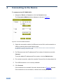
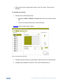
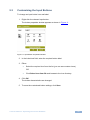
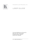
1
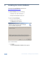
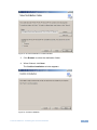
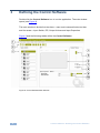
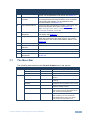
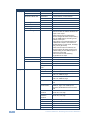
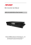
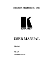
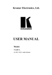
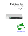
KR AMER ELECTRON ICS LT D. USER GUIDE Control Software for VP-728, VP-729, VP-730, VP-731 P/N: 2900-300091 Rev 1 Contents 1 Introduction 1 2 2.1 Installing the Control Software Connecting the PC 2 5 3 3.1 3.2 3.3 3.4 3.5 3.6 Defining the Control Software The Menu Bar The Command Button Tool Bar Input Switches PIP Controls Output Volume Control Input Properties 6 7 9 10 10 10 11 4 Connecting to the Device 12 5 5.1 5.2 5.3 Operating the Control Software Switching an Input to an Output Using the Preset Display Configurations Customizing the Input Buttons 13 13 13 15 Figures Figure 1: Welcome Window Figure 2: Choose Destination Location Window Figure 3: Confirm Installation Figure 4: Installation Progress Window Figure 5: Installation Complete Window Figure 6: Control Software Main Window Figure 7: Input Button Figure 8: Connection Method Window Figure 9: Input Selection Figure 10: Split Screen Window Figure 11: Input Button Properties Window 2 3 3 4 4 6 10 12 13 14 15 Control Software – Contents i 1 Introduction Control Software for VP-728, VP-729, VP-730, VP-731 is an optional software application for remotely controlling the Kramer VP-728, VP-729, VP-730 and VP-731 presentation switcher/scalers from a PC via either the RS-232 serial port or the Ethernet port. Using this software you can operate the scaler, controlling features (depending on the model of your switcher) such as: • Selecting an input video signal: composite, component, computer graphics, HDMI or a graphic from a USB source • Selecting an input audio signal: balanced, unbalanced or digital S/PDIF • Controlling the output: picture-in-picture, picture+picture, split screen, freeze frame and video output blanking • Controlling the volume • Changing picture parameters and audio settings The Control Software application can be downloaded from the Kramer Web site: http://www.kramerelectronics.com This guide describes how to install and operate your Control Software. We recommend that you review its contents before proceeding. The information described in this manual is based on the information given in the User Manuals for the VP-728/29/30/31. For further explanations, see the User Manual of the respective device. Control Software - Introduction 1 2 Installing the Control Software Download the Control Software application from http://www.kramerelectronics.com. The Control Software requires the following: • Windows™ XP, Vista or Windows™ 7 • Microsoft .Net Framework version 3.5 To install the Control Software: 1. Double click the Setup.exe file. The Welcome window appears: Figure 1: Welcome Window 2. Click Next. The Choose Destination Location window appears: 2 Control Software - Installing the Control Software Figure 2: Choose Destination Location Window 3. Click Browse to select the destination folder. 4. When finished, click Next. The Confirm Installation window appears: Figure 3: Confirm Installation Control Software - Installing the Control Software 3 5. Click Next. The Installation Progress window appears: Figure 4: Installation Progress Window Then the Installation Complete window appears: Figure 5: Installation Complete Window 4 Control Software - Installing the Control Software 6. Click Close. An icon appears on the desktop and a shortcut appears in the Start Menu Programs folder in the Kramer sub-folder. 2.1 Connecting the PC Refer to the user manual of the specific device for instructions on how to connect the device to a PC. Control Software - Installing the Control Software 5 3 Defining the Control Software Double-click the Control Software icon to run the application. The main window opens (see Figure 6). The main window is divided into two bars – menu and command button tool bar; and four areas – Input Switch, PIP, Output Volume and Input Properties. Figure 6 and the following tables define the Control Software. Figure 6: Control Software Main Window 6 Control Software - Defining the Control Software Main Window Features # Feature Function 1 Menu Bar Bar containing all the menus used for configuration and control. For an explanation of all menus, see Section 3.1 2 Command Button Tool Bar Buttons used for saving and opening predefined setups, connecting and disconnecting the device to be controlled and selecting PIP settings. For an explanation of all command buttons, see Section 3.2 3 Input Switch Buttons Click one of the 9 input buttons to select a main input. The selected input button turns green, see Section 3.3 Note: The input switch button configuration is dependent on the type of switcher connected 3.1 4 PIP Input Switch Dropdown Click to choose the source of the picture to insert in the PIP display, see Section 3.4 5 Output Volume Slider Drag the slider up to increase the output volume; drag the slider down to decrease the output volume. The volume level is shown in the volume level indicator, feature 7, see Section 3.5 6 PIP Preview Window This window shows how the PIP feature is configured 7 Volume Level Indicator Shows the output volume numerically from -100 to +28 8 Mute Checkbox Click this checkbox to turn off/on the output volume 9 Refresh Button Rereads and reloads the present main Input settings 10 Input Properties Dropdowns The properties displayed depend on the input chosen, see Section 3.6 The Menu Bar The following table describes the Control Software menu bar options. Menu Sub Menu 1 File Open Open an existing profile Save Saves the input label configuration Device Sub Menu 2 Description Exit Exit the Control Software Connect/Disconnect Connects or disconnects the controlled device Factory reset Returns the device to its preset default settings Refresh Refreshes the information on the screen Panel Lock Prevents tampering with the front panel buttons. Settings: On/Off Panel Save Lock Select On or Off Set to ON to save the lock status when the machine is powered down Panel Input Lock Select On or Off Set to OFF so you can still use the SOURCE buttons on the front panel even when the lock button is on Control Software - Defining the Control Software 7 Menu Sub Menu 1 Display Presets Sub Menu 2 Description Full. PIP, Pic plus Pic, Split Output Resolution Resolution Mode Set Set Mode 1 1400x1050x60, 1680x1050x60 Set Mode 2 1280x1024x75, 1280x1024x76 Set Mode 3 1280x768x60, 1366x768x60 HDMI Type Auto, HDMI, DVI Frame Lock On, Off Auto Image Manual, auto Switching Mode Seamless, fast HDCP Setting Select Follow Input or Follow Output to define whether the HDCP will follow the input or the output When Follow Input is selected, the scaler changes its HDCP output setting (for the HDMI output) according to the HDCP of the input This option is recommended when the HDMI scaler output is connected to a splitter/switcher (in this mode, switching may not be glitch-free) When Follow Output is selected, the scaler matches its HDCP output to the HDCP setting of the HDMI acceptor to which it is connected This ensures smooth switching, regardless of the input Blank Mute on, mute off Freeze Advanced Image 8 Properties Mute on, mute off Logo Off, on, custom Blank color Black, blue Background color Black, blue, custom Output gamma Adjust the gamma: Gamma 1, 2, 3 Film mode Set the film mode: Auto, Video, Film Temporal NR Set the temporal noise reduction level: Off, Low, Medium, High Mosquito NR Set the Mosquito noise reduction level: Off, Low, Medium, High Block NR Set the block noise reduction level: Off, On Detail enhancement Set the detail enhancement: Off, Low, Medium, High. If the USB input is selected, Detail Enhancement is set to Off Luma transition enhance Set the luminance transition enhance level: Off, Low, High Chroma transition enhance Set the chrominance transition enhance level: Off, Low, High Brightness Adjust the brightness: 0 to 100 Contrast Adjust the contrast: 0 to 100 Color Adjust the color: 0 to 100 Hue Adjust the hue: 0 to 360 Sharpness 0-100 Control Software - Defining the Control Software Menu Sub Menu 1 Sub Menu 2 Description Audio Properties Type Select the audio input type (available for IN 1 to IN 2): Analog or S/PDIF Setup Loudness Set the loudness: On/Off Delay Define the delay type: Dynamic or User Define Select Dynamic for the audio delay to equal the pipeline video delay or User Define to set the delay time manually (via User Delay) User Delay Available when selecting the User Defined delay: 0 to 340 (msec) Set the delay in 2msec steps USB Select the audio signal to follow the USB signal: No audio, input 1, input 2 HDMI 1 Select the audio source to be embedded: HDMI 1 HDMI 2 Select the audio source to be embedded: HDMI 2 Input volume Adjust the input volume: -22 to +22 Output volume Adjust the output volume: -100 to +24 Bass Adjust the bass: -36 to 36 Treble Adjust the treble: -36 to 36 Balance Adjust the balance: -10 to 10 Store Setup memory 1 – 8 Recall Setup memory 1 – 8 About 3.2 Displays the Control Software version and Kramer company details The Command Button Tool Bar The following table describes the Control Software Command Buttons. Button Button Name Description Open Open an existing profile Save Saves the input label configuration Connect/Disconnect Connects or disconnects the controlled device Preset Full Switches to a full-screen output Preset PIP Switches to a picture-in-picture output Preset Pic+Pic Switches to a picture-and-picture output Preset Split Switches to a split screen output Freeze Window Freezes the output display Set visibility of window Blanks/shows the output display Control Software - Defining the Control Software 9 3.3 Input Switches Figure 7 shows a typical input button. Figure 7: Input Button # Feature Description 1 1 Input number 2 3.4 User-selectable icon displayed on the button (see Section 5.3) 3 Label 1 INPUT 1 User-selectable button label 4 Background Color Indicates the status of the input/output: Green—active; White—inactive PIP Controls The PIP controls determine which source is inserted into the secondary display. The chosen configuration (full, PIP, P&P, split screen) is shown in the PIP preview window (the actual video output is not shown here). 3.5 Output Volume Control The Output Volume frame contains the volume slider to increase and decrease the output volume, a volume level indicator (that runs from -100 to 28) and a mute checkbox to turn off and on the output volume. 10 Control Software - Defining the Control Software 3.6 Input Properties The following table describes the Input Properties frame. i Switch Input 1-4 Input 5-6 Input 7-8 Input 9 Note: The fields displayed are dependent on the type of switcher connected and the type of input chosen. Field 1 Field 2 Parameters Source Type Component H-position Sets the horizontal position of the display: 0-1000 V-position Sets the vertical position of the display: 0-1000 Phase Sets the input phase: 0-31 Source Type Y/C Video standard Sets the video standard: Auto, NTSC, PAL Source Type Video Video standard Sets the video standard: Auto, NTSC, PAL UXGA1 H-position Sets the horizontal position of the display: 0-1000 V-position Sets the vertical position of the display: 0-1000 Frequency Sets the frequency for UXGA inputs: 0-50 HDMI1 USB Phase Sets the input phase: 0-31 Color format Sets the color format: Auto, RGB, YUV HDMI switch behavior Set to DVD/Normal or PC/Bypass HDMI Input HDCP Set to On or Off for each HDMI input HDCP support can be enabled (On) or disabled (Off) for each of the HDMI inputs, allowing the source to transmit a non-HDCP signal if required (for example, when working with a Mac computer) Slide show Sets the speed of the slide show: Long, Max, Off Control Software - Defining the Control Software Set to Normal for sources with HDCP. When in Normal operation, the unit sends a hot plug to the source for any Group/Scaler switching request. There might be some graphic cards that might shut OFF the VGA/HDMI output following the hot plug detection. To prevent this, set this parameter to the Bypass mode so the unit will not send a hot plug for switching request (the hot plug will be detected by the source only when plugging a physical connection) 11 4 Connecting to the Device To connect to the VP-728/29/30/31: 1. Navigate to Device > Connect or click the Connect button. The Connection Method window displays as shown in Figure 8. Figure 8: Connection Method Window 2. Select the connection method (via Ethernet over a LAN, serial connection or USB) by selecting the relevant option button. All switchers connect via RS-232. The VP-729 and VP-731 also connect via Ethernet. No devices currently connect via USB. 3. For Ethernet, enter the IP address and Port number of the device and click Connect. To set the default IP address and Port number, click the Default button. 4. For a serial connection, select the required Com port from the drop-down list. 5. The USB connection is not currently available. 6. Click Connect. If the connection is successful, the main window shown in Figure 6 appears. If the connection is not successful, a timeout error message appears. 12 Control Software - Connecting to the Device 5 Operating the Control Software 5.1 Switching an Input to an Output To switch an input to the output: • Click on the required input switch button to activate it. The input is selected and the button changes to green as shown in Figure 9. Figure 9: Input Selection 5.2 Using the Preset Display Configurations The output display can be configured using the presets: full, PIP, P+P and split. • Full shows the full-screen display of the chosen Input Switch • PIP shows the full display of the chosen Input Switch with an inserted image selected from the PIP Input Switch. The user can relocate the inserted image by dragging the window and resize it by dragging the corner of the window • P+P shows the chosen Input Switch display side-by-side with the chosen PIP Input Switch display. The displays are equal sized and do not cover the full screen. They cannot be dragged or resized Control Software - Operating the Control Software 13 • Split shows the two images side-by-side on the full screen. There may be distortion To activate the presets: 1. Choose one of the following ways: Navigate to Menu > Display > Presets and choose the desired preset OR Click one of the preset tool bar command buttons Figure 10 shows a split screen window. Figure 10: Split Screen Window 2. Choose the second source by selecting an input from the PIP Inputs Switch. 3. Change input properties as desired in the Input Properties frame. 14 Control Software - Operating the Control Software 5.3 Customizing the Input Buttons To change an input button icon and label: 1. Right-click the relevant input button. The button properties window appears as shown in Figure 11. Figure 11: Input Button Properties Window 2. In the Label text field, enter the required button label. 3. Either: Select the required icon from the list (you can save custom icons) OR Click Select icon from file and browse to the icon directory 4. Click OK. The button characteristics are changed. 5. To save the customized button settings, click Save. Control Software - Operating the Control Software 15