1
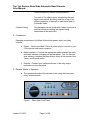
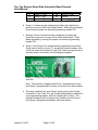
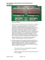
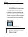
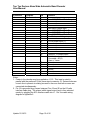
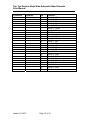
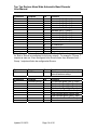
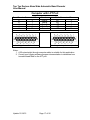
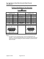
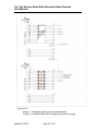
BAND AIDE AUTOMATIC BAND DECODER 1. Features Overview The Top Ten Devices Band Aide is an accessory that attaches to your radio (or computer), decodes the band data provided by the radio, and provides automatic selection of band specific devices, such as antennas and filters. The decoder responds instantly to your QSY, properly selecting the right antenna, or even the right amplifier. Here are some of its features: Supported Radios Yaesu*, Icom*, and Elecraft K3. Other radios are supported by attaching the decoder to the computer’s LPT port. *Check your radio’s manual to determine whether your model provides band data to external devices. Bands Decoded Yaesu: Icom: K3: LPT: 160 through 10, including WARC 160, 80, 60*, 40, 30, 20, 17/15, 12/10, 6m* * Consult your manual for compatibility on these bands. 160 through 6, including WARC and 60m Logging software dependent Manual Override Although intended to be left in Automatic most of the time, the unit is provided with a rotary selector switch, allowing manual selection of each of the 11 amateur bands. No Microprocessors The Band Aide is designed to do its job well, and requires no software programming/configuration. There are no USB ports, and no software drivers required, resulting in consistent performance from initial set up. Hi RFI Immunity 12Vdc CMOS logic provides high immunity to RFI. High Current Outputs Two sets of eleven relay outputs, each rated at 3A. Each of the two sets can be configured for either sink or 12Vdc source operation, providing flexibility to Update 11/10/13 Page 1 of 26 Top Ten Devices Band Aide Automatic Band Decoder User Manual control virtually any station switching device. Two sets of five relay outputs activated by the front panel rotary switch, providing selection of up to five different antennas or devices on each band when in Automatic mode. Contest Pairing Two decoders can be joined with a cable to provide a positive lockout preventing two signals being transmitted at the same time. 2. Connections Required connections to the Band Aide include power, radio, and relay outputs: a. Power – Use the provided 2.5mm dc power plug to connect to your 12V source at rear panel connector. b. Radio interface – Connect the appropriate cable between the radio and radio interface connector on the rear panel. Top Ten Devices sells cables to interface the Band Aide to many of the popular Icom, Yaesu, and Elecraft radios. c. Outputs – Connect your switched devices to the relay output connectors on the rear panel. 3. Decoder Modes of Operation a. The operational mode of the decoder is set using the front panel rotary selector switch: Figure 1 – Band Aide Front Panel Update 12/18/15 Page 2 of 26 Top Ten Devices Band Aide Automatic Band Decoder User Manual b. There are two modes of decoder operation, as determined by the position of the front panel rotary selector switch: i. Automatic – Rotate the front panel selector to any of the positions A1 through A5. In this mode, the decoder follows the radio’s frequency, and provides outputs to select the appropriate band-specific antenna/device. Positions A1 through A5 are identical with respect to the normal operation of the decoder in Automatic mode, and it is recommended that the selector be left in position A1. Positions A2 through A5 positions provide useful flexibility in configuring the decoder for multiple antennas for a given band. This is explained in more detail below. In Auto, the LED for the detected band is illuminated. (It should be noted that if the radio is in cross-band split, the band decoded is the TRANSMIT VFO’s band.) ii. Manual – Rotate the selector away from A1-A5 until the LED corresponding to the selected band is illuminated. The internal decoder is disabled in this mode of operation. Only the relay outputs for the manually selected band are activated. iii. LED Colors – LEDs for the six contesting bands are red; the WARC bands, 60m and 6m have yellow LEDs. c. Alternate Antennas in Automatic Mode i. In any of the A1 through A5 positions, the decoder is in automatic mode, and is decoding the band data from the radio. The relay outputs for the radio’s band are activated. See Para. 4.a below. In this sense, positions A1 through A5 are totally equivalent. If there is only a single antenna or other band-specific device available for any band, then the selector switch should be left in Position A1. ii. If the station configuration includes more than one antenna or band-specific device on one or more bands, Positions A2 through A5 provide a convenient way to select these devices. iii. The front panel green “Antenna” LEDs are a visual que as to which set of antennas has been selected. See Figure 1. Update 12/18/15 Page 3 of 26 Top Ten Devices Band Aide Automatic Band Decoder User Manual iv. Separate relay contacts are provided corresponding to the A1 through A5 positions of the rotary selector switch. These are present on the rear panel on a dedicated connector. v. Some examples of how this feature could be used: 1. A1 selects CW band antennas, A2 selects SSB band antennas 2. A1 selects main antennas, A2 selects secondary antennas Further explanation of how to use this feature, along with actual examples, are contained in later sections of this manual. Summary – Modes of Operation Rotary Selector Switch provides manual selection of the 11 bands, as well as automatic detection of the radio’s band. In automatic mode, the selector switch allows manual selection of up to 5 antennas or devices for the detected band. LEDs provide visual feedback for automatic and manual band selection. 4. The Relay Outputs a. The relay contact outputs for the 11 bands are arranged in two groups, Group 1 and Group 2, for a total of 22 contact outputs. Pin 1 2 3 4 5 6 7 8 9 10 Update 12/18/15 Function Group 1 – 10m Group 1 - 15m Group 1 - 20m Group 1 - 40m Group 1 - 80m Group 1 - 160m Group 1 - 30m +12Vdc output Ground Group 1 - 17m Page 4 of 26 Pin 14 15 16 17 18 19 20 21 22 23 Function Group 2 – 10m Group 2 - 15m Group 2 - 20m Group 2 - 40m Group 2 - 80m Group 2 - 160m Group 2 - 30m Group 2 - 17m Group 2 - 12m Group 2 - 6m Top Ten Devices Band Aide Automatic Band Decoder User Manual 11 Group 1 - 12m 24 Group 2 - 60m 12 Group 1 - 6m 25 Ground 13 Group 1 - 60m Figure 2 – Pinouts of Relay Output Connector J2 (DB25F) b. Group 1 contacts can be configured as either sink (switched to ground) or source (0Vdc when deactivated, 12Vdc when activated) by moving the jumper on internal programming header PH1. c. Similarly, Group 2 contacts can be configured as either sink (switched to ground) or source (0Vdc when deactivated, 12Vdc when activated) by moving the jumper on internal programming header PH2. d. Group 1 and Group 2 are independently programmed, and either Group can be sink or source. To access the jumper headers, take off the top cover and locate PH1 and PH2 in the rear right corner of the relay board, as shown in the following photograph: Photo 1 – Group 1 and 2 sink/source configuration headers PH1 and PH2 Note: The decoder is shipped with Group 1 programmed for sink and Group 2 programmed for source, as shown in the photo above. e. The relay contacts from each Group, before going to the Output Connector J2 (ref. Para. 4.a), are routed through what is referred to as a programming header, which is actually an IC socket. The decoder is shipped with a “jumper plug” installed in both Group 1 and Group 2 programming headers, as shown below: Update 12/18/15 Page 5 of 26 Top Ten Devices Band Aide Automatic Band Decoder User Manual Photo 2 – Group 1 and 2 Programming Headers with jumper plugs installed (as shipped) f. As can be seen in the above photo, the relay outputs for the various bands come into programming header on one side and the lines connecting to the output connector are on the other side. It is important to note that if these two jumper plugs are left in place, the relay output contacts for each Group and each band appear on output connect J2 as shown in Figure 2 in Para. 4.a. However, by removing one or both of these jumpers, the relay contacts from various bands can be combined in various ways. A typical example would be to combine the 10, 15, and 20m relay outputs so that a single external antenna relay would select a tribander. Use of these headers to “program the outputs” provides the station owner with a very powerful method of automatically selecting the desired antennas and other devices as the radio’s frequency band is changed. Detailed examples of this will be given later. g. In Automatic (positions A1 through A5 on the rotary switch), the decoder continues to decoder the band data from the radio and the appropriate relays are activated. Positions A1 through A5 are totally equivalent with respect to the band decoding function. However, an additional set of 5 relays are activated by the selector switch in positions A1 through A5. i. The outputs of the relays associated with A1 through A5 appear on output connector J3. ii. There are two sets of five contacts. Each set is either sink or source configured. Update 12/18/15 Page 6 of 26 Top Ten Devices Band Aide Automatic Band Decoder User Manual iii. The sink or source configuration for each set (Group) is set by the jumper on programming headers PH1 and PH2. Therefore, if the Group 1 set of main decoder outputs are configured for sink operation installing the jumper on PH1 to short pins 2 and 3, then the Group 1 outputs are also configured to sink operation. Detailed examples of how to use these outputs are shown later in the manual. Summary – Relay Outputs Group 1 – Individual contacts for 11 bands, sink or source selectable Group 2 – Individual contacts for 11 bands, sink or source selectable Programming Headers available for both Group 1 and Group 1 band relay outputs 2 sets of 5 auxiliary contacts available for selection of external devices, corresponding to the A1-A5 position of the rotary selector switch Examples of typical configurations are shown elsewhere in this manual. 5. Pairing with a Second Band Aide Decoder for Contest MultiRadio Operation a. Competitive SO2R and multi-operator contest stations often have two or more stations that are capable of operating on the same band. Sometime, the rules state that only one signal can be on the air at any time, regardless of band. Adherence to these types of contest rules require that a positive interlock be provided to prevent violations. b. In such a contest station, two Band Aide decoders can be interconnected such that their associated transmitters will be prevented from transmitting (“inhibited”) in the event that both radios are on the same band. This not only assures rules compliance, but also avoids accidental radio damage that may occur otherwise. Update 12/18/15 Page 7 of 26 Top Ten Devices Band Aide Automatic Band Decoder User Manual c. The Band Aide can directly inhibit (prevent from transmitting) the following radios: i. Elecraft K3 – Set TX INH in the menu to “HI = Inh” ii. Most modern desktop Yaesu transceivers, such as FT1000/2000/5000/9000 etc. (The Yaesu radios are by default set to inhibit the transmitter on a 12 Vdc signal on the inhibit line.) The control signal that inhibits the transmitter is included in the interface cable between the radio and the decoder. d. Interconnection of the two decoders is accomplished with a cable connecting the J5 “Data IO” jacks on the rear panels of both decoders. This cable shares band data between the two decoders. e. The decoder also has an input for the “PTT” line from the other transmitter, so that the decoder knows when the other transmitter is on the air. f. Response of the band decoder to the external data (other radio’s band data and PTT status) is set by operation of S1, which is a small 4-circuit toggle switch located on the read panel: Photo 3 – Decoder Pairing Function Selector Switch S1 (Shown with S1-1 through S1-3 off, and S1-4 on.) S1 ON 1+3 Response My transmitter will be inhibited when: The other radio is on a different band and then goes into transmit OR the other radio is not transmitting, but moves to my band My transmitter will be inhibited when: 2 The other radio is on my band Update 12/18/15 Page 8 of 26 Top Ten Devices Band Aide Automatic Band Decoder User Manual My transmitter will be inhibited when: 3 4 The other radio is transmitting. Blinks the LED when both radios are on the same band. 6. Limited Warranty – Top Ten Devices warrants this unit to be free from defects in parts and workmanship for a period of one year. The unit will be either repaired or replaced, at our discretion. The only cost will be the cost of return shipping. If repairs are required during the warrantee period for other than manufacturing or parts defects, an estimate of the repair cost will be provided prior to repair. Top Ten Devices is not responsible for any consequential damages to other equipment or personnel injury as a result of using this product, or any of the suggested uses. If the terms of the above Warrantee and Limitation of Liability are not acceptable, please return the unit to Top Ten Devices for a full refund. 7. Specifications Power Supply Voltage ............................................ +12 to +15 volts dc Current required (no relays).................................... 100 mA Output current capability Each relay contact ............................................. 1 A each Total for the entire unit ...................................... 2 A Appendices 1. Connector Pin Assignments 2. Radio Interface Cable Wiring 3. Output Contact Configuration Examples 4. Blank Output Contact Configuration Worksheet Update 12/18/15 Page 9 of 26 Top Ten Devices Band Aide Automatic Band Decoder User Manual Appendix 1 Connector Pin Assignments Update 12/18/15 Page 10 of 26 Top Ten Devices Band Aide Automatic Band Decoder User Manual Decoder Rear Panel Connectors (Rear View) Connector J1 Purpose Radio interface Type DB25F J2 Antenna relays DB25F J3 Alternate Antenna Selection DA15F J4 J5 12Vdc Power Decoder Pairing 2.5mm DB9F J7 Radio PTT Input to decoder RCA Update 12/18/15 Page 11 of 26 Function Top Ten Devices Band Aide Automatic Band Decoder User Manual Connector J1 Purpose Radio interface Pin 1 2 3 4 5 6 7 8 9 10 11 12 13 14 15 16 17 18 19 20 21 22 23 24 25 Function No connection Yaesu/K3/LPT Band Data A input No connection No connection No connection Icom Band Voltage input Yaesu/K3/LPT Band Data B input Yaesu/K3/LPT Band Data C input Yaesu/K3/LPT Band Data D input Icom Reference Voltage input No connection +12Vdc power input (1) No connection No connection No connection No connection No connection Yaesu/K3 TX Inhibit output K3 Inhibit level select: Grounded = K3(2) Open = Yaesu Ground Ground Ground Ground Ground Ground Notes: 1. Power to the decoder may be supplied on J1-12. This input is wired in parallel with the preferred 12Vdc power input connector J4. Series diodes are in each line to prevent circulating currents in the even that both sources are connected simultaneously. 2. Pin 19 is grounded by a jumper between Pins 19 and 20 on the K3 radio interface cable plug. The proper inhibit signal output level is thus selected merely by plugging the K3’s interface cable into J1. Ref. the cable wiring diagram in Appendix 2. Update 12/18/15 Page 12 of 26 Top Ten Devices Band Aide Automatic Band Decoder User Manual Connector J2 Purpose Relay Outputs Update 12/18/15 Pin 1 2 3 4 5 6 7 8 9 10 11 12 13 14 15 16 17 18 19 20 21 22 23 24 25 Function Group 1 – 10m Group 1 - 15m Group 1 - 20m Group 1 - 40m Group 1 - 80m Group 1 - 160m Group 1 - 30m +12Vdc output Ground Group 1 - 17m Group 1 - 12m Group 1 - 6m Group 1 - 60m Group 2 – 10m Group 2 - 15m Group 2 - 20m Group 2 - 40m Group 2 - 80m Group 2 - 160m Group 2 - 30m Group 2 - 17m Group 2 - 12m Group 2 - 6m Group 2 - 60m Ground Page 13 of 26 Top Ten Devices Band Aide Automatic Band Decoder User Manual Connector J3 Purpose Alternate Ants Pin Function 1 Alternate Ant 1 - Group 2 2 Alternate Ant 1 - Group 1 3 Alternate Ant 2 - Group 2 4 Alternate Ant 2 - Group 1 5 Alternate Ant 3 - Group 2 6 Alternate Ant 3 - Group 1 7 Alternate Ant 4 - Group 2 8 Alternate Ant 4 - Group 1 9 Alternate Ant 5 - Group 2 10 Alternate Ant 5 - Group 1 11 No connection 12 No connection 13 No connection 14 +12Vdc 15 Ground Note: Alternate Antenna Outputs Group 1 and Group 2 follow the programming for Sink or Source as configured for the main outputs. For example, if Group 1 outputs as seen on J2 are configured to be Source lines, then Alternate Ant x – Group 1 outputs will also be configured at Source. Connector J4 Purpose +12Vdc power Pin Function Center 12Vdc power to the decoder and external antenna relays Connector J5 Purpose Decoder pairing Pin 1 2 3 4 5 6 7 8 9 Update 12/18/15 Function This decoder Band Data A output This decoder Band Data B output This decoder Band Data C output This decoder Band Data D output Other decoder Band Data A input Other decoder Band Data B input Other decoder Band Data C input Other decoder Band Data D input Ground Page 14 of 26 Top Ten Devices Band Aide Automatic Band Decoder User Manual Appendix 2 Radio Interface Cable Wiring Update 12/18/15 Page 15 of 26 Top Ten Devices Band Aide Automatic Band Decoder User Manual Yaesu Radios with Band Data Jack Band Decoder Connector / Pin J1 2 J1 7 J1 8 J1 9 J1 25 J1 18 J1 12 Function Data A Data B Data C Data D Ground TX Inhibit (1) +12Vdc (2) Looking at rear of decoder Radio Connector / Pin Band Data 4 Band Data 5 Band Data 6 Band Data 7 Band Data 3 Band Data 8 Band Data 1 Looking at radio rear panel Notes: 1. TX Inhibit connection between decoder and radio is required for pairing with another Band Aid Decoder for same-band lockout. See discussion in Paragraph 5. a. This wire is included in the pre-made cable available from Top Ten Devices. b. If homebrewing this cable, and no pairing with another Band Aid Decoder is intended, then connect this wire to J2-24 (Ground) in lieu of J2-18. This permanently enables the radio to transmit. 2. The recommended way to power the decoder is via power input connector J4 on the decoder’s rear panel. A well-regulated power supply should be used. It is possible, but not recommended, to power the decoder from the radio by connecting J2-12 to Band Data Jack Pin 1. Extreme caution is advised, as a short on this line could blow a fuse internal to the radio (best case) or cause damage to the radio (worst case). This wire is not included in pre-made cables available from Top Ten Devices. 3. The radio’s Band Data jack is not a standard 8-pin DIN, but rather is a “262 degree” version. Your Yaesu distributor can provide you with the correct plug. Attempted use of a standard 270 degree plug will break the jack on the radio. Update 12/18/15 Page 16 of 26 Top Ten Devices Band Aide Automatic Band Decoder User Manual Computer with LPT Port Band Decoder Connector / Pin J1 2 J1 7 J1 8 J1 9 J1 25 Function Data A Data B Data C Data D Ground Looking at rear of decoder Radio Connector / Pin LPT 2 LPT 7 LPT 8 LPT 9 LPT 25 Looking at computer rear panel Notes: 1. A 25-wire straight through computer cable is suitable for this application. 2. Consult your logging software program documentation to determine how to enable band data on the LPT port. Update 12/18/15 Page 17 of 26 Top Ten Devices Band Aide Automatic Band Decoder User Manual Icom Radios with 7-Pin ACC2 Jack Band Decoder Connector / Pin J1 6 J1 25 J1 10 J1 12 Function Band Voltage Ground Ref. Voltage +12Vdc (1) Looking at rear of decoder Radio Connector / Pin ACC2 4 ACC2 2 ACC2 1 ACC2 7 Looking at radio rear panel Notes: 1. The recommended way to power the decoder is via power input connector J4 on the decoder’s rear panel. A well-regulated power supply should be used. It is possible, but not recommended, to power the decoder from the radio by connecting J2-12 to ACC2 Pin 7. Extreme caution is advised, as a short on this line could blow a fuse internal to the radio (best case) or cause damage to the radio (worst case). This wire is not included in premade cables available from Top Ten Devices. Update 12/18/15 Page 18 of 26 Top Ten Devices Band Aide Automatic Band Decoder User Manual Elecraft K3 Band Decoder Connector / Pin J1 2 J1 7 J1 8 J1 9 J1 25 J1 18 J1 19 J1 20 Function Data A Data B Data C Data D Ground TX Inhibit (1) Jumper (2) Looking at rear of decoder Radio Connector / Pin ACC 13 ACC 3 ACC 9 ACC 14 ACC 5 ACC 7 Looking at radio rear panel Notes: 1. TX Inhibit connection between decoder and radio is required for pairing with another Band Aid Decoder for same-band lockout. See discussion in Paragraph 5. This wire is included in the pre-made cable available from Top Ten Devices. 2. Pins 19 and 20 are jumpered on the DB25M connector. 3. K3 must be set to inhibit the transmitter on a 12Vdc signal on J2-18. Go to CONFIG > TX INH and select “HI = Inh”. Update 12/18/15 Page 19 of 26 Top Ten Devices Band Aide Automatic Band Decoder User Manual Pairing Cable Between Two Decoders for Transmit Inhibit Band Decoder 1 Connector / Pin J5 1 J5 2 J5 3 J5 4 J5 5 J5 6 J5 7 J5 8 J5 9 Function Band Data A -> Band Data B -> Band Data C -> Band Data D -> <- Band Data A <- Band Data B <- Band Data C <- Band Data D Ground Looking at rear of decoder Band Decoder 2 Connector / Pin J5 5 J5 6 J5 7 J5 8 J5 1 J5 2 J5 3 J5 4 J5 9 Looking at rear of decoder Notes: 1. This cable is used to exchange radio current band data between two decoders. In the event that both radios are on the same band, both radios will be prevented from sending RF (transmit inhibited) to protect the other radio’s front end. Update 12/18/15 Page 20 of 26 Top Ten Devices Band Aide Automatic Band Decoder User Manual Appendix 3 Output Contact Configuration Examples Work in Progress – More Examples to be added Inquire to [email protected] with specific questions. Update 12/18/15 Page 21 of 26 Top Ten Devices Band Aide Automatic Band Decoder User Manual Figure A3-1 – As shipped configuration. Band outputs appear directly on corresponding J2 pins, due to jumper plug installed. Ref. Para. 4.f. Update 12/18/15 Page 22 of 26 Top Ten Devices Band Aide Automatic Band Decoder User Manual Figure A3-2: Group 1 – Tribander and four mono-band antennas Group 2 – DuneStar Model 600 configured for positive keying Update 12/18/15 Page 23 of 26 Top Ten Devices Band Aide Automatic Band Decoder User Manual Appendix 4 Blank Output Contact Configuration Worksheet Update 12/18/15 Page 24 of 26 Top Ten Devices Band Aide Automatic Band Decoder User Manual Figure A4-1 – Blank Worksheet. NOTE: Select Sink or Source for each of Group 1 and 2 Output banks at PH1 and PH2 respectively. Update 12/18/15 Page 25 of 26 Top Ten Devices Band Aide Automatic Band Decoder User Manual Revision History 11/10/13 On pages 16-19, the Band Aide input connector was incorrectly listed as J2. Fixed to J1. 1/19/14 Added 60 and 6m as decoded bands for some models of Icom transceivers. Users should review their radio owner’s manual to determine whether their particular model supports these bands. 12/18/15 Fixed pinouts on J3 (Group 1 and Group 2 were reversed) on Page 22 and 26. Page 16, Fixed Yaesu Band Data Pin for 12Vdc to Pin 1. Update 12/18/15 Page 26 of 26


![TR4W User Manual [English Version]](http://vs1.manualzilla.com/store/data/005728234_1-e27c4fea1c6d513d6e0fdc1451ef66f1-150x150.png)