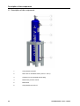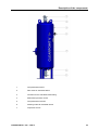
1
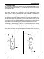
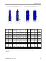
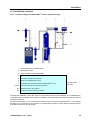
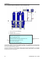
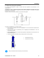
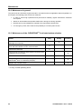
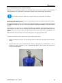
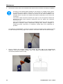
EN - english Instructions for installation and operation Activated-carbon adsorber without dust filter CLEARPOINT® L 205 – L295 V Dear customer, ® Thank you for deciding in favour of the CLEARPOINT V activated-carbon adsorber. Please read these ® installation and operating instructions carefully before mounting and starting up the CLEARPOINT V activated-carbon adsorber and follow our directions. Perfect functioning of the activated-carbon adsorber can only be guaranteed when the provisions and notes stipulated here are strictly adhered to. 2 CLEARPOINT® L 205 – L295 V Type plate CLEARPOINT® V activated-carbon adsorber 1 Type plate CLEARPOINT® V activated-carbon adsorber Manufacturer: BEKO TECHNOLOGIES GMBH 41468 Neuss, Germany Phone: +49 2131 988-0 www.beko.de Year of construction: Type: Serial no.: Max. permissible operating pressure PS: Working pressure: Min./max. permissible temperature TS: Compressed-air inlet temperature: Max. volume flow at the INLET Weight approx.: Please enter the data from the type plate of the activated-carbon adsorber here! CLEARPOINT® L 205 – L295 V 3 Contents 2 Contents ® 1 Type plate CLEARPOINT V activated-carbon adsorber.................................................................3 2 Contents ............................................................................................................................................4 3 General advice ..................................................................................................................................6 4 Safety instructions .............................................................................................................................7 4.1 Safety labelling ..................................................................................................................................7 4.1.1 Safety pictograms in accordance with DIN 4844...............................................................................7 4.1.2 Signal words in accordance with ANSI..............................................................................................8 4.2 General safety instructions ................................................................................................................9 4.3 Special advice for plants under pressure in accordance with the 97/23/EC Pressure Equipment Directive...........................................................................................................................................13 5 Residual risk ....................................................................................................................................14 6 Field of application and proper use of the CLEARPOINT V activated-carbon adsorber ...............14 7 Applied EU directives and harmonised standards...........................................................................15 8 General description of the CLEARPOINT V activated-carbon adsorber .......................................16 9 Operating principle ..........................................................................................................................17 10 Technical data .................................................................................................................................18 10.1 Technical data CLEARPOINT L 205-295 V...................................................................................18 10.2 Available options..............................................................................................................................20 10.3 Filter selection table.........................................................................................................................21 11 Description of the components........................................................................................................22 12 Transport and set-up .......................................................................................................................24 12.1 Safety during transport and set-up ..................................................................................................24 12.2 Transport .........................................................................................................................................24 12.3 Set-up ..............................................................................................................................................25 13 Installation .......................................................................................................................................26 13.1 Safety during the installation............................................................................................................26 13.2 Minimum requirements....................................................................................................................28 ® ® ® 13.2.1 Filtration of the compressed air .......................................................................................................28 13.2.2 Water content of the compressed air ..............................................................................................28 13.2.3 Inlet temperature of the compressed air..........................................................................................28 13.3 Installation examples .......................................................................................................................29 ® 13.3.1 Installation diagram CLEARPOINT V with a refrigeration dryer ....................................................29 ® 13.3.2 Installation diagram CLEARPOINT V with an adsorption dryer .....................................................30 13.4 Work steps during the installation ...................................................................................................31 14 Start-up............................................................................................................................................32 14.1 Safety during the start-up ................................................................................................................32 14.2 Check prior to the start-up...............................................................................................................33 4 CLEARPOINT® L 205 – L295 V Contents 14.3 Initial start-up ...................................................................................................................................34 14.4 Restart .............................................................................................................................................35 14.5 Removal from service......................................................................................................................35 15 Troubleshooting and fault elimination..............................................................................................36 15.1 Safety during troubleshooting and fault elimination.........................................................................36 15.2 Status and alarm indications ...........................................................................................................38 16 Maintenance ....................................................................................................................................40 16.1 Safety during maintenance..............................................................................................................40 16.2 Maintenance in general ...................................................................................................................42 16.3 Maintenance of the CLEARPOINT V activated-carbon adsorber..................................................42 ® 16.3.1 Replacement of the activated carbon..............................................................................................43 16.4 Periodic inspections.........................................................................................................................45 17 Dismantling and disposal ................................................................................................................46 18 List of spare parts............................................................................................................................47 19 EC Declaration of Conformity..........................................................................................................47 CLEARPOINT® L 205 – L295 V 5 General advice 3 General advice ® Prior to starting up the CLEARPOINT V activated carbon adsorber, it must be ensured that the operating staff are instructed and skilled according to these instructions for installation and operation with regard to the set-up, monitoring, operation and maintenance of the plant, as well as to the safety measures to be observed. The operating instructions must be accessible at all times at the place of application of the device. Non-observance of the installation and operating instructions involves risks for persons and systems. If you have any queries regarding these instructions, please contact BEKO TECHNOLOGIES GMBH. 6 CLEARPOINT® L 205 – L295 V Safety instructions 4 Safety instructions 4.1 Safety labelling Safety instructions whose non-observance represents a threat to life and physical condition or can lead to property damage are labelled in accordance with DIN 4844 and ANSI Z535. 4.1.1 Safety pictograms in accordance with DIN 4844 General danger symbol Quickly escaping compressed air Note Observe operating instructions Use eye protection Wear light breathing protection Use protective gloves Wear ear protectors CLEARPOINT® L 205 – L295 V 7 Safety instructions 4.1.2 Signal words in accordance with ANSI Danger! Imminent hazard Consequences of non-observance: serious injury or death Warning! Potential hazard Consequences of non-observance: possible serious injury or death Caution! Imminent hazard Consequences of non-observance: possibly injury or property damage Notice! Potential hazard Consequences of non-observance: possibly injury or property damage Important! Additional advice, info, hints Consequences of non-observance: disadvantages during operation and maintenance, no danger 8 CLEARPOINT® L 205 – L295 V Safety instructions 4.2 General safety instructions Installation works must exclusively be carried out by authorised and qualified skilled ® personnel. Prior to undertaking any measures on the CLEARPOINT V, the skilled personnel shall read up on the device by carefully studying the operating instructions. The operator is responsible for the adherence to these provisions. The respective directives in force apply to the qualification and expertise of the skilled personnel. For safe operation, the device must only be installed and operated in accordance with the indications in the operating instructions. In addition, the national and operational statutory provisions and safety regulations, as well as the accident prevention regulations required for the respective case of application, need to be observed during employment. This applies accordingly when accessories are used. Danger! Compressed air! Risk of serious injury or death through contact with quickly or suddenly escaping compressed air or through bursting and/or unsecured plant components. All types of installation, maintenance and repair works must only be carried out when the ® CLEARPOINT V is pressureless. It is the operator’s duty to ensure that the connected pressure generator is secured against exceeding of the maximum operating overpressure and the temperature limits at the ® CLEARPOINT V. Pressure relief valves used need to be arranged in such a manner that endangering of persons is excluded. Where required, observe the manufacturer's additional advice. Suitable and permissible arming devices need to be provided in accordance with the local regulations. The max. permissible operating parameters, such as the operating overpressure, temperature and volume flow must not be exceeded. The max. permissible operating parameters are specified on the type plate and in the technical data (see "Technical data" section). Never make structural modifications to the plant! Use suitable tools and genuine spare parts and accessories only! Only use fittings and connecting elements that are approved for this application. It is of vital importance to observe the specifications of the respective manufacturer. Ensure that the connections are installed according to good professional practice. Only use pipes, valves and fittings which are suitable for the pressure and temperature range. It is of vital importance to observe the specifications of the manufacturer. Sudden impact through pressure build-up can cause damage and escape of compressed air. Avoid a sudden pressure build-up by operating the valves slowly. Check all pipe connections subsequent to the installation and retighten them if necessary! The general safety and accident prevention regulations apply! Prior to the start-up, a leak test needs to be carried out. This test shall only be effected by correspondingly qualified skilled personnel in compliance with the safety regulations. Caution! Unauthorised intervention! Unauthorised interventions may endanger persons and plants and lead to malfunction. CLEARPOINT® L 205 – L295 V 9 Safety instructions Unauthorised interventions, modification and abuse of the pressure device are prohibited. Operators of the devices must observe the local and national pressure equipment regulations in the country of installation. Danger! High pressure! Subsequent to the start-up, components of the plant are under pressure. Risk of serious injury or death through contact with quickly or suddenly escaping compressed air or through bursting and/or unsecured plant components. Any installation, repair and maintenance works must only be carried out when the plant is disconnected, pressureless and de-energised. Warning! Improper use and application! Improper use and application can lead to injury and damage to plants. The following use is considered improper and is therefore prohibited: Exceeding the max. permissible operating pressure Exceeding the max. permissible operating temperature Exceeding the max. permissible volume flow All individual cases of application which are described as improper Caution! Improper transport! Improper transport can lead to injury and damage to plants. ® The CLEARPOINT V must only be transported and installed by qualified and authorised skilled personnel. Only use suitable and technically unobjectionable lifting tools! Only use lifting tools with a sufficient carrying capacity! The respective national regulations and directives in force must be adhered to. Otherwise, personal injuries may occur. NOTE! Damage through defective components! Under no circumstances should you start up a damaged CLEARPOINT components can impair the operational reliability and cause further damage. ® V. Defective Caution! Incorrect installation! ® Incorrect installation of the CLEARPOINT V may endanger persons. ® Ensure that the personnel in charge of the installation of the CLEARPOINT V are sufficiently instructed and competent for this task. 10 CLEARPOINT® L 205 – L295 V Safety instructions Danger! Incorrect start-up! The incorrect start-up of the CLEARPOINT ® V may endanger persons. ® Prior to starting up the CLEARPOINT V, it must be ensured that the operating staff are instructed according to these instructions for installation and operation with regard to the setup, monitoring, operation and maintenance of the plant, as well as to the safety measures to be observed. CAUTION! Operational reliability at risk! ® Overloading the CLEARPOINT V can compromise the operational reliability! Observe the permissible temperature range! Do not exceed the permissible volume flow! NOTE! Operational reliability at risk! Incorrect installation can compromise the operational reliability and affect service measures. The clear diameter of the pipe joint must be at least as large as the mounting dimension of ® the CLEARPOINT V. It is strongly recommended to install a shut-off valve both upstream and downstream of the ® CLEARPOINT V for the implementation of service measures. To maintain the supply of compressed air during service failures, maintenance and repair ® ® works on the CLEARPOINT V, the installation of a bypass line around the CLEARPOINT V is advisable. This bypass line must have a shut-off valve. Danger! Mishandling! ® Mishandling of the CLEARPOINT V may endanger persons. ® Prior to starting up the CLEARPOINT V, it must be ensured that the operating staff are instructed according to these instructions for installation and operation with regard to the setup, monitoring, operation and maintenance of the plant, as well as to the safety measures to be observed. CLEARPOINT® L 205 – L295 V 11 Safety instructions Danger! Incorrect maintenance! ® The incorrect maintenance of the CLEARPOINT V may endanger persons. Ensure that the personnel in charge of the operation, monitoring and maintenance of the ® CLEARPOINT V are sufficiently instructed and competent for this task. Caution! Activated-carbon dust! Eyes and respiration are endangered through quickly or suddenly escaping activatedcarbon dust. Activated carbon can produce dust and wear debris! Use eye protection! During the start-up of the activated-carbon adsorber, compressed air might escape and cause a very loud expansion noise. Wear silencing ear protectors. Wear personal protective clothing! Wear light breathing protection at strong dust development! Caution! Activated carbon produces dust and wear debris! Endangering through dust explosion. Use suitable tools and ex-protection-tested suction plants and accessories. Observe the safety instructions. 12 CLEARPOINT® L 205 – L295 V Safety instructions 4.3 Special advice for plants under pressure in accordance with the 97/23/EC Pressure Equipment Directive ® The CLEARPOINT V activated-carbon adsorber is a pressure device in the sense of the 97/23/EC Pressure Equipment Directive. Therefore, the plant needs to be registered with the supervisory authority in accordance with the local regulations, and requires the approval of the latter. For the examination prior to the start-up and for periodic inspections, the national regulations need to be observed, such as the industrial safety regulation in the Federal Republic of Germany. In countries outside the EU, the respective regulations in force there need to be adhered to. The proper use of pressure devices is the basic requirement for safe operation. As regards pressure devices, the following needs to be observed: The CLEARPOINT V must only be employed within the pressure and temperature range limits indicated by the manufacturer on the type plate. No welding must be carried out on the pressure vessel of the device. The CLEARPOINT V must neither be installed in insufficiently ventilated rooms nor near heat sources or inflammable substances. To avoid fractures resulting from material fatigue, the CLEARPOINT V should not be exposed to vibrations during operation. The maximum operating pressure indicated by the manufacturer on the type plate must not be exceeded. It is the operator's responsibility to install the appropriate safety and control devices. ® Prior to the start-up of the CLEARPOINT V, the connected pressure generator (compressor etc.) must be safeguarded against exceeding of the max. permissible operating pressure. The integrated safeguard needs to be checked by an approved inspection agency. The documents related to the CLEARPOINT V (manual, operating instructions, manufacturer's declaration etc.) must be kept safe for future reference. No objects whatsoever must be installed or placed on the CLEARPOINT V and the connecting lines. Installation of the plant in frost-free places only. ® ® ® ® ® WARNING! Unauthorised intervention! Unauthorised interventions may endanger persons and plants and lead to malfunction. Unauthorised interventions, modification and abuse of the pressure devices are prohibited. Operators of the devices must observe the local and national pressure equipment regulations in the country of installation. Warning! High pressure! Subsequent of the start-up of the CLEARPOINT pressure. Serious injuries are possible. ® V components of the plant are under ® Any installation, repair and maintenance works on the CLEARPOINT V must only be carried out when the plant is pressureless. CLEARPOINT® L 205 – L295 V 13 Residual risk 5 Residual risk The plant offers state-of-the-art technology. However, certain residual risks remain. Risk through disregard of the safety instructions. The safety instructions included in these operating instructions point to further residual risks. It is, therefore, of vital importance to observe all safety instructions. 6 Field of application and proper use of the CLEARPOINT® V activated-carbon adsorber ® These operating instructions apply exclusively to the tank variants of the CLEARPOINT L205 V to L295 V activated-carbon adsorbers from BEKO TECHNOLOGIES GMBH and refer to the device type without dust filter and internal tubing. ® The CLEARPOINT V activated-carbon adsorber must only be applied under the conditions described in this user manual, and only in connection with the components recommended or approved by the manufacturer. The field of application comprises the reduction of oil vapours and odorous substances from compressed air or nitrogen. The system is intended for the use under industrial conditions inside buildings. Any other use is considered improper. The manufacturer shall not be liable for problems occurring as a consequence of improper use. The operator alone is responsible for any hazard resulting from that. Please check, prior to reading the operating instructions, whether or not these instructions correspond to the device. Read these installation and operating instructions carefully prior to any intervention regarding ® the CLEARPOINT V. The operating instructions must be accessible at all times at the place of application of the device. If you have any queries regarding these instructions, please contact BEKO TECHNOLOGIES GMBH. To ensure safe operation, the device must only be operated and maintained in accordance with the indications in the operating instructions. In addition, the national and operational statutory provisions and safety regulations, as well as the accident prevention regulations required for the respective case of application, need to be observed during employment. This applies accordingly when accessories are used. Non-observance of the installation and operating instructions involves risks for persons and systems. Proper functioning and trouble-free operation of the activated-carbon adsorber is only ensured when the transport, storage, set-up, installation, operation and maintenance are carried out in accordance with the advice included in this user manual. To handle the plant, the personnel must be trained to deal with devices of the compressed-air technology and need to know the contents of this user manual as far as handling is concerned. To start up and maintain the plant, the personnel must be familiar with the safety concepts of the compressed-air technology. The personnel must be authorised and trained in such a manner that they are capable of starting up and maintaining such facilities. ® The proper employment and use of the CLEARPOINT V according to the directions requires the exact compliance with the installation instructions, in particular in respect of: 14 CLEARPOINT® L 205 – L295 V Applied EU directives and harmonised standards The place of installation, installation conditions The pressure and temperature of the inlet air The ambient temperature The device is supplied as accepted in the factory. The operator only needs to establish the connections with the compressed-air system, which is described in the following chapters. WARNING! Improper use! The following is considered as improper use and is prohibited: 7 Exceeding the max. permissible operating pressure Exceeding the max. permissible operating temperature Exceeding the max. permissible volume flow Employment of the CLEARPOINT V in hazardous areas All individual cases of application which are not described as proper us ® Applied EU directives and harmonised standards Applied EU directives: 97/23/EC Pressure Equipment Directive Harmonised standards applied: EN 10216-2: EN 10028-2: EN 10242: Seamless steel tubes for pressure purposes. Technical delivery conditions Part 2: Non-alloy and alloy steel tubes with specified elevated temperature properties Flat products made of steels for pressure purposes - Part 2: Non-alloy and alloy steels with specified elevated temperature properties Threaded pipe fitting in malleable cast iron AD-2000 bulletins CLEARPOINT® L 205 – L295 V 15 General description of the CLEARPOINT® V activated-carbon adsorber 8 General description of the CLEARPOINT® V activated-carbon adsorber ® The CLEARPOIINT L 205-295 V activated-carbon adsorbers serve exclusively to separate residual oil contents in the form of vapour or aerosol from compressed air and nitrogen. The compressed air should be predried, and should not exceed a moisture content of 30% and a temperature of +35°C. Exceeding these values will reduce the service life of the activated-carbon adsorber. Therefore, the employment of a refrigeration or even an adsorption dryer is required upstream of the activated-carbon adsorber. With an appropriate dimensioning and when the operating parameters and load limits of the incoming compressed air on which the dimensioning is based are adhered to, the oil content is drastically reduced through the activated carbon contained in the adsorber. Besides the temperature, operating pressure and volume flow, the exact life expectancy and dimensioning depends on the applied type of oil, the compressor type and the humidity of the compressed air. The following modifications of the operating conditions may lead to a reduction in the activated-carbon adsorber’s service life: Increase of the volume flow Increase of the operating pressure Increase of the relative humidity of the compressed air Increase of the residual oil aerosol content at the inlet. Therefore, you should benefit from the expertise of our special departments to design your activatedcarbon adsorber. Depending on the actual quality of the compressed air in your supply network, a prefilter and at least a refrigeration dryer is required for the incoming compressed air. The prefilter ensures that the oil aerosol 3 content of the incoming compressed air does not exceed a value of 0.01 mg/m . By treating the compressed air with a refrigeration dryer, the maximum permissible humidity of the compressed air of 30% at the inlet into the adsorption dryer is guaranteed. Not included in the scope of delivery: 16 Prefilter Refrigeration dryer / adsorption dryer Afterfilter Internal tubing Oil check indicator CLEARPOINT® L 205 – L295 V Operating principle 9 Operating principle The CLEARPOINT® V activated-carbon adsorber from BEKO TECHNOLOGIES GMBH functions according to the principle of the accumulation of oil molecules on the surface and in the porous structures of special activated carbon. The activated carbon is in a container, through which the medium flows continuously top down. The compressed air, from which the oil fractions need to be removed, enters the device through the upper connection at the container. Prior to that, the compressed air must have been filtered at least through a prefilter (residual oil aerosol content 0.01 mg/m³ at +20°C) and should not exceed a relative humidity of 30% and a temperature of +35°C. The service life of the activated-carbon adsorber will be reduced when these values are exceeded. Therefore, the employment of a refrigeration dryer or even an adsorption dryer upstream of the activated-carbon adsorber is required. The compressed air flows through a compressed-air distributor and travels top down through the volume filled with activated carbon. During this process, the activated carbon adsorbs the majority of the oil aerosols and the oil vapour. Subsequently, the compressed air purified in this manner flows to the outlet through the lower compressed-air distributor. This process takes place without regeneration phases. The activated carbon is thus gradually saturated with oil molecules and therefore needs to be replaced when the predefined service life has expired. Activated carbon is able to reliably adsorb a wide range of non-polar hydrocarbons; there are, however, restrictions regarding the adsorption capacity as far as polar hydrocarbons are concerned (e.g. benzene). It must also be taken into account that abruptly changing operating conditions (pressure, volume flow) may lead to desorption of the already intercalated hydrocarbons. It is explicitly recommended to provide a shut-off valve both upstream and downstream of the activatedcarbon adsorber and to install a bypass around the activated-carbon adsorber. These components are not included in the scope of delivery. Flow chart CLEARPOINT® L 205 – 230 V CLEARPOINT® L 205 – L295 V Flow chart CLEARPOINT® L 240 – 295 V 17 Technical data 10 Technical data ® 10.1 Technical data CLEARPOINT L 205-295 V ® Name CLEARPOINT L 205-295 V Manufacturer BEKO TECHNOLOGIES GMBH Germany, 41468 Neuss, Im Taubental 7 Type Minimum ambient temperature Activated-carbon adsorber Compressed air Saturated up to 30% Free from water or condensate Free from aggressive or corrosive components +5°C Maximum ambient temperature +50°C Maximum air volume flow at the inlet See table Minimum compressed-air inlet temperature +2°C Maximum compressed-air inlet temperature +50°C Recommended compressed-air inlet temperature +35°C* Recommended residual humidity of the compressed air at the inlet < 30%* Minimum operating pressure 4 bar(g) Max. permissible operating overpressure L 205275 V 16 bar(g) Max. permissible operating overpressure L 295 V 11 bar(g) Recommended operating pressure 7 bar(g) Residual oil content at the outlet max. 0.003 mg/m³ Adsorbent Activated carbon type 1 Service life at nominal performance data and reference conditions Approx. 10,000 operating hours Compressed-air connection See table Height x width x depth approx. See table Weight approx. See table Category acc. to PED 97/23/EC – fluid group 2 See table Medium Design data pressure vessel Design pressure L 205-275 V 16 bar(g) Design pressure L 295 V 11 bar(g) Design temperature -10 / +50°C Test pressure hydraulic L 205-275 V 22.9 bar(g) Test pressure hydraulic L 295 V 15.8 bar(g) Design and construction Acc. to PED 97/23/EC and AD-2000 * The service life of the activated-carbon adsorber is reduced when this value is exceeded 18 CLEARPOINT® L 205 – L295 V Technical data Dimensions CLEARPOINT® L 205 – 230 V Type Volume flow* Connection [m³/h] Dimensions CLEARPOINT® L 240 – 295 V Activated Weight carbon Category A** B** C** D** E** [mm] [mm] [mm] [mm] [mm] [kg] [kg] Fluid gr. 2 PED 97/23/EC L 205 V 135 G1 1580 340 340 405 270 13 60 II L 210 V 155 G1 1490 340 340 405 280 21 85 II L 215 V 200 G1 1490 340 340 405 280 21 85 II L 220 V 280 G1 ½ 1850 450 450 530 380 42 130 III L 225 V 380 G1 ½ 1850 450 450 530 380 42 130 III L 230 V 500 G1 ½ 1810 450 450 530 380 57 160 III L 240 V 630 G2 1980 420 560 - 105 68 200 III L 250 V 800 G2 1940 470 590 - 105 85 220 III L 260 V 1000 G2 ½ 1970 570 700 - 120 120 260 IV L 275 V 1250 G2 ½ 1970 570 700 - 120 120 260 IV L 295 V 1550 G2 ½ 2080 620 730 - 120 160 330 IV * Maximum volume flow at the inlet acc. to ISO 7183, related to +35°C and 7 bar(g) ** ±10 mm CLEARPOINT® L 205 – L295 V 19 Technical data 10.2 Available options It is recommended to use a BEKO ultrafilter with an automatic condensate drain. This prefilter ensures that the oil aerosol content of the incoming air does not exceed a value of 0.01 mg/m³. Prefilter For details, please refer to the following filter selection table. Downstream of each activated-carbon adsorber, an afterfilter (minimum requirement 1 µm) must be installed that retains dusts and particles from the activated carbon that develop due to the way the system operates. Afterfilter It is recommended to use a BEKO dust filter in an oil and greasefree version. For details, please refer to the following filter selection table. Compressed-air dryer Oil check indicator ® For the safe functioning of the CLEARPOINT® V, the compressed air must not exceed a relative humidity of 30% at the inlet into the activated-carbon adsorber. The service life of the activated-carbon adsorber will be reduced when these values are exceeded. Therefore, the employment of a refrigeration or even an adsorption dryer is required upstream of the activated-carbon adsorber. Please contact our specialist departments to select a suitable compressed-air dryer. For the rough assessment of the compressed-air quality, an oil check indicator can be used. The oil check indicator can be installed on the head of the CLEARPOINT dust filter (you will find the adapter and oil check indicator, as well as replacement test tubes, in our price list). METPOINT OCV residual oil measuring device For the continuous qualitative assessment of the compressed-air ® quality, the use of our METPOINT OCV residual oil measuring device ® is advisable. By means of a measuring section, the METPOINT OCV can be installed in the pipework downstream of the afterfilter, and will then show the residual oil vapour content ONLINE. Service determination residual oil content Our service department will be happy to submit you a corresponding offer for the cyclic qualitative assessment of the compressed-air quality. 20 CLEARPOINT® L 205 – L295 V Technical data 10.3 Filter selection table Option dust filter Option prefilter Filter + filter elements purified without oil Model Ultrafilter Dust filter outlet (0.01 µm / 0.01 mg/m³ *) Filter element (1 µm / 0.1 mg/m³ *) Filter element L 205 V S075SWTX 07S M010RFWM-OF 10F-OF L 210 V S075SWTX 07S M012RFWMX-OF 12F-OF L 215 V M010SWT 10S M015RFWM-OF 15F-OF L 220 V M015SWT 15S M018RFWM-OF 18F-OF L 225 V M018SWT 18S M020RFWMX-OF 20F-OF L 230 V M020SWTX 20S M022RFWMX-OF 22F-OF L 240 V M022SWT 22S M023RFWM-OF 23F-OF L 250 V M023SWT 23S M025RFWM-OF 25F-OF L 260 V M025SWT 25S M027RFWM-OF 27F-OF L 275 V M025SWT 25S M030RFWMX-OF 30F-OF L 295 V M027SWT 27S M032RFWMX-OF 32F-OF *at 20°C and 1 bar absolute according to ISO 8573 CLEARPOINT® L 205 – L295 V 21 Description of the components 11 Description of the components 22 1 Compressed-air INLET 2 Filler neck for activated carbon (not for L 205 V) 3 Container for the activated-carbon filling 4 Manometer pressure vessel 5 Base frame 6 Compressed-air OUTLET CLEARPOINT® L 205 – L295 V Description of the components 1 Compressed-air INLET 2 Filler neck for activated carbon 3 Container for the activated-carbon filling 4 Manometer pressure vessel 5 Compressed air OUTLET 6 Draining nozzle for activated carbon 7 Inspection access CLEARPOINT® L 205 – L295 V 23 Transport and set-up 12 Transport and set-up 12.1 Safety during transport and set-up IMPORTANT! Danger through improper transport! ® The CLEARPOINT V must only be transported and installed by qualified and authorised skilled personnel. Only use suitable and technically sound lifting tools! Only use lifting tools with a sufficient carrying capacity! The respective national regulations and directives in force must be adhered to. Otherwise, personal injuries may occur. IMPORTANT! Danger through damaged components! Under no circumstances should you start up a damaged CLEARPOINT components can impair the operational reliability and cause further damage. ® V. Defective 12.2 Transport ® The CLEARPOINT V activated-carbon adsorber was thoroughly tested and packed prior to leaving the factory. It was in a perfect condition when handed over to the forwarding agent. ® Despite all due care, transport damage cannot be excluded. Therefore, check the CLEARPOINT V for possible transport damage subsequent to transport and removal of the packaging material. The forwarding agent and BEKO TECHNOLOGIES or the BEKO TECHNOLOGIES agency must be informed immediately about any kind of damage. If no evident damage to the packaging or the plant was ascertained but hidden defects are detected at a later moment in time, the forwarding agent must immediately be informed so as to allow him to assess and document the damage. In the event that the plant is damaged, it is imperative to contact the manufacturer to know whether or not the system may be started up. Please observe the following points regarding the transport: 24 Provide suitable lifting tools for the transport. Persons in charge of the transport must have the corresponding qualification. With the lifting tools, the activated-carbon adsorber must only be lifted at the intended points (transport pallet, frame, eyebolts on the top of the container). Observe the weight of the activated-carbon adsorber and the maximum permitted load of the lifting tools and means of transport used. National regulations regarding accident prevention must be adhered to. CLEARPOINT® L 205 – L295 V Transport and set-up 12.3 Set-up Provide suitable lifting tools for the transport and set-up. ® Secure the CLEARPOINT V against shifting on the load platform or fork-lift truck. ® Move the CLEARPOINT V to the place of installation. ® The function and service life of the CLEARPOINT V depends on the conditions at the place of installation. This place must meet the following requirements: The device is installed within a building. The device must not be operated in explosive or fire-endangered atmospheres, in an environment with aggressive chemicals, superheated steam or strong contamination, or in a very hot environment. The CLEARPOINT V must be protected against moisture. The ambient temperature must not exceed/undercut the indications in the "Technical data" section. Choose an even, solid and vibration-free set-up area. The weight of the CLEARPOINT V must be taken into account when choosing the area. No vibrations must be transferred to the CLEARPOINT V. If necessary, install the activatedcarbon adsorber on vibration dampers. The pipework must be free from mechanical stress (otherwise risk of bursting). It must be ensured that vibrations from other plant components cannot be transferred. This also and particularly concerns the pulsation of the compressed air as otherwise, the activated carbon may be destroyed. Set up the CLEARPOINT V in such a manner that the plant is easily accessible from the sides. For checks of the pressure vessels, maintenance and repair measures, sufficient free space ® must be available on all sides (at least 1.5 m) around the CLEARPOINT V. Install the activated-carbon adsorber in such a manner that the front panel with the manometer is well accessible. The activated-carbon adsorber must be fixed on the floor area by means of the bores in the frames or feet. In particular as far as devices without a frame construction are concerned, the tank needs to be secured against tilting at the intended place of installation. In the further course of the installation, the pipes and dust filters (not included in the scope of delivery) must be fixed separately, if required. Ensure sufficient ventilation and heat removal. Keep a safe distance from transport routes when setting up the CLEARPOINT V. Equip the plant with a suitable collision guard. ® ® ® ® ® In the event of doubt, we recommend obtaining expert advice regarding the place of installation. ® Remove the packaging of the CLEARPOINT V. ® Move the CLEARPOINT V to the place of installation. ® Position the CLEARPOINT V at the desired place and adjust the plant accordingly. CLEARPOINT® L 205 – L295 V 25 Installation 13 Installation 13.1 Safety during the installation Installation works must exclusively be carried out by authorised and qualified skilled ® personnel. Prior to undertaking any measures on the CLEARPOINT V, the skilled personnel shall read up on the device by carefully studying the operating instructions. The operator is responsible for the adherence to these provisions. The respective directives in force apply to the qualification and expertise of the skilled personnel. For safe operation, the device must only be installed and operated in accordance with the indications in the operating instructions. In addition, the national and operational statutory provisions and safety regulations, as well as the accident prevention regulations required for the respective case of application, need to be observed during employment. This applies accordingly when accessories are used. DANGER! Compressed air! Risk of serious injury or death through contact with quickly or suddenly escaping compressed air or through bursting plant components. All types of installation, maintenance and repair works must only be carried out when the ® CLEARPOINT V is pressureless. It is the operator’s duty to ensure that the connected pressure generator is secured against exceeding of the maximum operating overpressure and the temperature limits at the ® CLEARPOINT V. Pressure relief valves used need to be arranged in such a manner that endangering of persons is excluded. Where required, observe the manufacturer's additional advice. Suitable and permissible safety arming devices need to be provided in accordance with the local regulations. The max. permissible operating overpressure must not be exceeded. The max. permissible operating overpressure is specified on the type plate and in the technical data (see "Technical data" section). Never make structural modifications to the plant! Use suitable tools and genuine spare parts and accessories only! Only use fittings and connecting elements that are approved for this application. It is of vital importance to observe the specifications of the respective manufacturer. Ensure that the connections are installed according to good professional practice. Only use pipes, valves and fittings which are suitable for the pressure and temperature range. It is of vital importance to observe the specifications of the manufacturer. Check all pipe connections subsequent to the installation and retighten them if necessary! Prior to the start-up, a leak test needs to be carried out. This test shall only be effected by correspondingly qualified personnel in compliance with the safety regulations. 26 CLEARPOINT® L 205 – L295 V Installation Danger! Incorrect installation! ® Incorrect installation of the CLEARPOINT V involves the risk of personal injury. ® Ensure that the personnel in charge of the installation of the CLEARPOINT V are sufficiently instructed and competent for this task. NOTE! Installation works! Installation works at the compressed-air system must only be carried out by skilled 1 personnel authorised by the operator. CAUTION! Danger through damaged components! Under no circumstances should you start up a damaged CLEARPOINT components can impair the operational reliability and cause further damage. ® V. Defective NOTE! Operational reliability at risk! Incorrect installation can compromise the operational reliability and affect service measures. The clear diameter of the pipe joint must be at least as large as the mounting dimension of ® the CLEARPOINT V. It is strongly recommended to install a shut-off valve both upstream and downstream of the ® CLEARPOINT V for the implementation of service measures. To maintain the supply of compressed air during service failures, maintenance and repair ® ® works on the CLEARPOINT V, the installation of a bypass line around the CLEARPOINT V is advisable. This bypass line must have a shut-off valve. 1 Authorised skilled personnel are persons who are authorised by the operator, with experience and technical training, who are well-grounded in the respective provisions and laws and capable of carrying out the required works and of identifying and avoiding any risks during the machine transport, installation, operation and maintenance. CLEARPOINT® L 205 – L295 V 27 Installation 13.2 Minimum requirements 13.2.1 Filtration of the compressed air Prefilter: Super-fine filter (S) with condensate drain max. residual content oil aerosols 0.01 mg/m³ at 20°C Afterfilter: Dust filter (F) with manual drain Particle classification 1 µm 13.2.2 Water content of the compressed air Max. permissible residual humidity: < 30% 13.2.3 Inlet temperature of the compressed air Recommended inlet temperature: + 35°C Non-observance of the indicated minimum requirements regarding the installation and permissible operating parameters can lead to drastic reduction of the service life of the ® CLEARPOINT V activated-carbon adsorber. 28 CLEARPOINT® L 205 – L295 V Installation 13.3 Installation examples ® 13.3.1 Installation diagram CLEARPOINT V with a refrigeration dryer 1 Universal filter (G) with BEKOMAT 2 Refrigeration dryer 3 Super-fine filter (S) with BEKOMAT 4 Activated-carbon adsorber 5 Dust filter (F) with manual drain 6 Sensor unit METPOINT OCV 7 Evaluation unit with user interface METPOINT OCV H1/H2 ® ® Oil- and greasefree zone Shut-off valves of the measuring section H3 Shut-off valve of the bypass H4 Vent valve of the measuring section ® The depicted installation shows the minimum requirement regarding the installation of a CLEARPOINT V activated-carbon adsorber. Other types of installation are possible (provided that they meet the defined operating conditions). ® For service measures, it is recommended to install a bypass around the CLEARPOINT V. This applies generally to all components to be serviced in compressed-air systems. Please observe that this bypass must also be free from oil and grease! CLEARPOINT® L 205 – L295 V 29 Installation ® 13.3.2 Installation diagram CLEARPOINT V with an adsorption dryer 1 Super-fine filter (S) with BEKOMAT 2 Adsorption dryer 3 Dust filter (F) with manual drain 4 Activated-carbon adsorber 5 Dust filter (F) with manual drain 6 Sensor unit METPOINT OCV 7 Evaluation unit with user interface METPOINT OCV H1/H2 ® ® Oil-and grease-free zone Shut-off valves of the measuring section H3 Shut-off valve of the bypass H4 Vent valve of the measuring section ® The depicted installation shows another installation possibility of the CLEARPOINT V activated-carbon adsorber that meets the minimum requirements. Other types of installation are possible (provided that they meet the defined operating conditions). ® For service measures, it is recommended to install a bypass around the CLEARPOINT V. This applies generally to all components to be serviced in compressed-air systems. Please observe that this bypass must also be free from oil and grease! 30 CLEARPOINT® L 205 – L295 V Installation 13.4 Work steps during the installation It is strongly recommended to install a shut-off valve both upstream and downstream of the ® CLEARPOINT V. To maintain the supply of compressed air during service failures, maintenance and repair works on the ® ® CLEARPOINT V, the installation of a bypass line around the CLEARPOINT V is advisable. This bypass line must have a shut-off valve. Installation example with prefilter, afterfilter, shut-off valves and bypass: ® To install the CLEARPOINT V, proceed as follows: Ensure that the conditions of use of the CLEARPOINT V are met and that the operation limits are not exceeded. Ensure that the system is pressureless prior to integrating the CLEARPOINT compressed-air system. Prior to installation, it must be ensured that all possible contaminations are removed from the compressed-air system. Connect the following connections with your supply system or with your plant: ® Compressed-air inlet (1) Compressed-air outlet (2) ® V into the Carry out a leak test of the connections prior to the start-up. CLEARPOINT® L 205 – L295 V 31 Start-up 14 Start-up 14.1 Safety during the start-up It is imperative to observe all specifications and notes in these installation and operating instructions Non-observance of the installation and operating instructions involves risks for persons and systems. If you have any queries regarding these instructions, please contact BEKO TECHNOLOGIES GMBH. Warning! Incorrect start-up! ® The incorrect start-up of the CLEARPOINT V involves the risk of personal injury. ® Prior to starting up the CLEARPOINT V, it must be ensured that the operating staff are instructed according to these instructions for installation and operation with regard to the setup, monitoring, operation and maintenance of the plant, as well as to the safety measures to be observed. DANGER! Compressed air! Risk of serious injury or death through contact with quickly or suddenly escaping compressed air or through bursting plant components. Maintenance, inspection and installation works must exclusively be carried out by authorised ® and qualified skilled personnel. Prior to undertaking any measures on the CLEARPOINT V the skilled personnel shall read up on the device by carefully studying the operating instructions. The operator is responsible for the adherence to these provisions. The respective directives in force apply to the qualification and expertise of the skilled personnel. It is the operator’s duty to ensure that the connected pressure generator is secured against exceeding of the maximum operating overpressure and the temperature limits at the ® CLEARPOINT V. Do not exceed the max. permissible operating overpressure. The max. permissible operating overpressure is specified on the type plate and in the technical data (see "Technical data" section). Sudden impact through pressure build-up can cause damage and escape of compressed air. Avoid a sudden pressure build-up by operating the valves slowly. The general safety and accident prevention regulations apply! CAUTION! Operational reliability at risk! ® Overloading the CLEARPOINT V can compromise the operational reliability! Observe the permissible temperature range! Do not exceed the permissible volume flow! Caution! Activated-carbon dust! Eyes and respiration are endangered through quickly or suddenly escaping activated32 CLEARPOINT® L 205 – L295 V Start-up carbon dust. Activated carbon can produce dust and wear debris! Use eye protection! During the start-up of the activated-carbon adsorber, compressed air might escape and cause a very loud expansion noise. Wear silencing ear protectors. Wear personal protective clothing! Wear light breathing protection at strong dust development! 14.2 Check prior to the start-up As regards the check prior to the start-up, the country-specific provisions need to be observed. The plant contains pressure equipment of different categories according to the 97/23/EC Pressure Equipment Directive. For this reason it is necessary to register the entire plant with the relevant authority in accordance with the local provisions and to have it approved. In countries outside the EU, the respective regulations in force there need to be adhered to. CLEARPOINT® L 205 – L295 V 33 Start-up 14.3 Initial start-up Please fill in the data from the type plate of the activated-carbon adsorber into the table on page 3! Work steps: ® Ensure that the conditions of use of the CLEARPOINT V are met and that the operation limits are not exceeded. Check the operating data of the plant and compare these with the permissible operating data from the "Technical data" section. Should you ascertain deviations, adjust the operating parameters according to the specifications. Ensure that all installation steps were carried out properly. Check whether or not the activated-carbon adsorber is completely tubed. If not, carry out proper installation. Check whether or not the shut-off valves upstream of the inlet and downstream of the outlet of the activated-carbon adsorber are closed. If not, close both shut-off valves. Set the compressed-air system under system pressure upstream of the shut-off valve on the entering side of the activated-carbon adsorber. If required, start the compressor. Open the shut-off valve upstream of the activated-carbon adsorber slowly. The activated-carbon adsorber is set under operating pressure. Filling of the activated-carbon adsorber with compressed air during the start-up must be implemented as slowly as possible. Under no circumstances must the flow rates which correspond to those of the nominal performance data be exceeded. Recommended amount of compressed air during the filling of the activated-carbon adsorber: Pressure build-up approx. 1 bar/min (or 1% of the nominal performance) This is particularly important during the initial start-up / subsequent to maintenance measures. Flow rates which are too high cause high pressure difference and impulselike strong abrasive wear on the activated carbon which can also overwhelm the downstream dust filter. Check all pipe connections for tightness. Open the shut-off valve downstream of the outlet filter slowly and set the entire compressed-air system under pressure. Filling of the downstream tank/pipe network must be implemented as slowly as possible and must, under no circumstances, exceed the flow rates of the nominal performance data. The operating pressure at the activated-carbon adsorber must be maintained (see manometer). This is particularly important during the initial start-up/subsequent to maintenance measures. Flow rates which are too high cause impulse-like strong abrasive wear on the activated carbon which can also overwhelm the downstream dust filter. 34 CLEARPOINT® L 205 – L295 V Start-up ® Prior to delivery, the CLEARPOINT V is operated dry in the factory. If the activated-carbon adsorber is not installed immediately after having been delivered, and if it is installed downstream of an adsorption dryer, it may be necessary to allow dry compressed air to flow through the activated-carbon adsorber for approximately four to six hours to remove the residual moisture from the activated carbon. ® If the activated-carbon adsorber is equipped with a METPOINT OCV, the initial start-up should be ® implemented without METPOINT OCV. To prevent the risk of contaminations through dust, the ® METPOINT OCV should only be installed after a trial run of several hours (for the installation of the probe, the plant section again needs to be unpressurised). ® Subsequent to the successful start-up, no other works are required. The CLEARPOINT V is now ready to operate. In the event that unexpected failures occur during the running operation, please inform the service technician who is responsible for you. 14.4 Restart ® If the CLEARPOINT V is restarted after a longer down time, proceed as during the initial start-up. ® Check, above all after completed maintenance or repair measures, whether the CLEARPOINT V is completely tubed. If not, carry out proper installation. 14.5 Removal from service For safety reasons, short-term removal from service should always be implemented together with the compressor. For the removal from service during maintenance or repair measures, please proceed as follows: Unpressurise the plant prior to any maintenance or repair measures! Open the bypass line (not included in the scope of delivery). Close the shut-off valves (not included in the scope of delivery) upstream and downstream of the activated-carbon adsorber. Unpressurise the activated-carbon adsorber. Stagnation pressure may occur in pipe sections or in the container due to plugging. It is imperative to observe the manometer at the container during the pressure reduction! Ensure that there is no stagnation pressure in pipe sections or in the container. This is particularly possible if the compressed-air distributor or the filter element of the afterfilter (not included in the scope of delivery) are blocked as a result of a large amount of wear debris. CLEARPOINT® L 205 – L295 V 35 Troubleshooting and fault elimination 15 Troubleshooting and fault elimination 15.1 Safety during troubleshooting and fault elimination Works regarding the troubleshooting and fault elimination must exclusively be carried out by authorised and qualified skilled personnel. Prior to undertaking any measures on the ® CLEARPOINT V, the skilled personnel shall read up on the device by carefully studying the operating instructions. The operator is responsible for the adherence to these provisions. The respective directives in force apply to the qualification and expertise of the skilled personnel. For safe operation, the device must only be operated and maintained in accordance with the indications in the operating instructions. In addition, the national and operational statutory provisions and safety regulations, as well as the accident prevention regulations required for the respective case of application, need to be observed during employment. This applies accordingly when accessories are used. Danger! Incorrect fault elimination! ® The incorrect fault elimination at the CLEARPOINT V involves the risk of personal injury. Ensure that the personnel in charge of the operation, supervision and maintenance of the ® CLEARPOINT V are sufficiently instructed and competent for this task. NOTE! Troubleshooting and fault elimination! Operations, system performance tests, installation, setting and maintenance measures at the 2 compressed-air system must only be carried out by skilled personnel authorised by the operator. 2 Authorised skilled personnel are persons who are authorised by the operator, with experience and technical training, who are well-grounded in the respective provisions and laws and capable of carrying out the required works and of identifying and avoiding any risks during the machine transport, installation, operation and maintenance. 36 CLEARPOINT® L 205 – L295 V Troubleshooting and fault elimination DANGER! Compressed air! Risk of serious injury or death through contact with quickly or suddenly escaping compressed air or through bursting plant components. All types of installation, maintenance and repair works must only be carried out when the ® CLEARPOINT V is pressureless. The max. permissible operating overpressure must not be exceeded. The max. permissible operating overpressure is specified on the type plate and in the technical data (see "Technical data" section). Never make structural modifications to the plant! Use suitable tools and genuine spare parts and accessories only! Only use pipes, valves and fittings which are suitable for the pressure and temperature range. It is of vital importance to observe the specifications of the manufacturer. Check all pipe connections subsequent to maintenance or repair measures and retighten them if necessary! Prior to the restart, a leak test needs to be carried out. This test shall only be effected by correspondingly qualified skilled personnel in compliance with the safety regulations. CLEARPOINT® L 205 – L295 V 37 Troubleshooting and fault elimination 15.2 Status and alarm indications Residual oil content too high Possible cause of failure Fault elimination Inlet volume flow too high Reduce the inlet volume flow Operating pressure too low Increase the operating pressure Reduce the compressed-air temperature at the inlet Install a precooler, if required Inlet filter elements exhausted Pressure difference too high Replace the inlet filter elements Use of oil-contaminated filters or filter elements downstream of the activated-carbon adsorber Use of BEKO filters and filter elements in an oil- and grease-free version Oil-contaminated circuit sections between the activated-carbon adsorber and the measuring point Clean the pipesection or install a new pipesection Check the functioning of the condensate drain (at the inlet filter), repair or replace it, if required Replace the activated carbon Compressed-air temperature at the inlet too high Condensate drainage upstream of the activatedcarbon adsorber does not work Max. absorption capacity of the activated carbon reached 38 CLEARPOINT® L 205 – L295 V Troubleshooting and fault elimination Container pressure too low / Operating pressure in the system too low Possible cause of failure Pressure difference of the inlet filter is too high The compressed-air system upstream of the activated-carbon adsorber is pressureless Larger amounts of wear debris in the system: clogged compressed-air distributor or filter elements Fault elimination Check the pressure drop via the inlet filter Replace the filter element, if required Check the compressed-air system upstream of the activated-carbon adsorber Eliminate any faults Replace the dust filter element Replace the activated carbon Clean the compressed-air distributor Verify the operating conditions (pulsation, volume flow) NOTE! In the event of malfunctions which are not listed here or which cannot be eliminated, please contact BEKO TECHNOLOGIES GMBH. CLEARPOINT® L 205 – L295 V 39 Maintenance 16 Maintenance 16.1 Safety during maintenance Maintenance, inspection and installation works must exclusively be carried out by authorised ® and qualified skilled personnel. Prior to undertaking any measures on the CLEARPOINT V the skilled personnel shall read up on the device by carefully studying the operating instructions. The operator is responsible for the adherence to these provisions. The respective directives in force apply to the qualification and expertise of the skilled personnel. For safe operation, the device must only be operated and maintained in accordance with the indications in the operating instructions. In addition, the national and operational statutory provisions and safety regulations, as well as the accident prevention regulations required for the respective case of application, need to be observed during employment. This applies accordingly when accessories are used. Danger! Incorrect maintenance! Incorrect maintenance of the CLEARPOINT ® V involves the risk of personal injury. Ensure that the personnel in charge of the operation, supervision and repair of the ® CLEARPOINT V are sufficiently instructed and competent for this task. NOTE! Maintenance works! Operation, system performance checks, installation, setting and maintenance measures at 3 the compressed-air system must only be carried out by skilled personnel authorised by the operator. 3 Authorised skilled personnel are persons who are authorised by the operator, with experience and technical training, who are well-grounded in the respective provisions and laws and capable of carrying out the required works and of identifying and avoiding any risks during the machine transport, installation, operation and maintenance. 40 CLEARPOINT® L 205 – L295 V Maintenance DANGER! Compressed air! Risk of serious injury or death through contact with quickly or suddenly escaping compressed air or through bursting plant components. All types of installation, maintenance and repair works must only be carried out when the ® CLEARPOINT V is pressureless. Do not exceed the max. permissible operating overpressure. The max. permissible operating overpressure is specified on the type plate and in the technical data (see "Technical data" section. Never make structural modifications to the plant! Use suitable tools and genuine spare parts and accessories only! Only use pipes, valves and fittings that are suitable for the pressure and temperature range. It is of vital importance to observe the specifications of the manufacturer. Check all pipe connections subsequent to maintenance or repair measures and retighten them if necessary! Prior to the restart, a leak test needs to be carried out. This test shall only be effected by correspondingly qualified skilled personnel in compliance with the safety regulations. Caution! Activated-carbon dust! Eyes and respiration are endangered through quickly or suddenly escaping activatedcarbon dust. Activated carbon can produce dust and wear debris! Use eye protection! During the start-up of the activated-carbon adsorber, compressed air might escape and cause a very loud expansion noise. Wear silencing ear protectors. Wear personal protective clothing! Wear light breathing protection at strong dust development! Caution! Activated carbon produces dust and wear debris! Endangering through dust explosion. Use suitable tools and ex-protection-tested suction plants and accessories. Observe the safety instructions. CLEARPOINT® L 205 – L295 V 41 Maintenance 16.2 Maintenance in general The plant must be checked at regular intervals in accordance with the applicable national regulations. In this respect, the following points need to be observed: In order to ensure high operational and performance reliability, regular maintenance measures are required. Watch for abnormalities and possible malfunctions during the running operation. Deficiencies must immediately be reported to the responsible units/persons. For emergency cases, there must be the possibility to cut off the plant section. 16.3 Maintenance of the CLEARPOINT® V activated-carbon adsorber Action daily Check the exterior of the plant for contaminations, damages and corrosion weekly x Record the current operating parameters and compare them with the indications under "Technical data" x Check the manometer x Check all pipe connections and threaded connections and retighten them if necessary Check the activated-carbon adsorber for leaks annually* x x Verify the result of the oil adsorption (e.g. by means of a ® METPOINT OCV or a laboratory analysis) x Replace the activated carbon x * or every 10,000 operating hours 42 CLEARPOINT® L 205 – L295 V Maintenance 16.3.1 Replacement of the activated carbon Depending on the operating conditions, the activated carbon has a service lifetime of approximately 10,000 operating hours. Afterwards, the adsorption capacity of the activated carbon is exhausted. As a matter of principle, replace the complete contents of the activated-carbon filling. The activated carbon must be replaced by a correspondingly trained and authorised specialist company. Please request the BEKO service. The employed activated carbon is not subject to any labelling obligation in accordance with the Ordinance on Hazardous Substances. However, the usual precautions regarding the handling of chemicals need to be taken. In the event of fire, there are no restrictions regarding the applicable fire-extinguishing agents. It is recommended to use CO2, powder or a directed spray of water; use a directed spray of water or alcoholresistant foam in the event of larger fires. Special personal protective equipment for firefighting is not required. Spilled activated carbon should be removed, avoiding dust to the largest possible extent. To replace the activated carbon, please carry out the following work steps: 1. Remove the plant from service. For this purpose, follow the directions in the "Removal from service" section. 2. Open the filler neck of the activated-carbon adsorber. As regards the CLEARPOINT L 205 V, unfasten the pipe connection at the compressed-air INLET, and unscrew and remove the compressed-air distributor. CLEARPOINT® L 205 – L295 V ® 43 Maintenance 3. Introduce the suction hose of an industrial suction device into the container and empty it completely. According to the industrial safety regulations, the selection of a suitable suction system is incumbent on the operator of the plant. In this respect, the relevant regulations of explosion protection need to be taken into account, as the dusts contained in the activated carbon may induce an explosive atmosphere, depending on the amount and consistency. The suction system should be checked with regard to the dust explosion hazard and approved for these areas (minimum requirement zone 22). Please use conductive accessories only. Where flammable vapours or gases exist, an additional approval for the gas explosion protection is required. Where contamination through toxic, harmful, mutagenic or mutation-promoting components is anticipated, suitable filters must additionally be provided. ® As regards the CLEARPOINT L 240-295 V, the drain nozzle at the bottom of the container can also be used. Subsequent to full drainage of the container, reclose this nozzle with seal and blind plug. 4. Fill the container with activated carbon until reaching the lower edge of the compressed-air distributor. Only use the original activated carbon from BEKO TECHNOLOGIES GMBH. Use a commercially available funnel for filling. 44 CLEARPOINT® L 205 – L295 V Maintenance ® 5. Mount the fill plug with a seal at the filler neck of the container. As regards the CLEARPOINT L 205 V, mount the compressed-air distributor and then re-establish the connection to the pipework. 6. Check the connections for tightness. In this respect, follow the directions in the "Initial start-up" section. 16.4 Periodic inspections ® The pressure vessel of the CLEARPOINT V activated-carbon adsorber must be checked at regular intervals by a technical expert or an authorised expert. The determination of the time limits regarding periodic inspections is incumbent on the operator and, depending on the classification into the pressure device category in accordance with the Pressure Equipment Directive, must be carried out by a certified inspection agency. CLEARPOINT® L 205 – L295 V 45 Dismantling and disposal 17 Dismantling and disposal ® When dismantling the CLEARPOINT V, all parts and operating media related to the plant must be disposed of separately. ® The CLEARPOINT V is supplied ready to operate with the following operating materials: ® Type C CLEARPOINT V Operating material Amount L 205 V Activated carbon type 2 13 kg L 210 V Activated carbon type 2 21 kg L 215 V Activated carbon type 2 21 kg L 220 V Activated carbon type 2 42 kg L 225 V Activated carbon type 2 42 kg L 230 V Activated carbon type 2 57 kg L 240 V Activated carbon type 2 68 kg L 250 V Activated carbon type 2 85 kg L 260 V Activated carbon type 2 120 kg L 275 V Activated carbon type 2 120 kg L 295 V Activated carbon type 2 160 kg Adsorbent! The activated carbon used must be supplied to proper disposal. The local regulations need to be observed. Waste code according to the EWC Waste code Waste designation 06 13 02 Used activated carbon 46 CLEARPOINT® L 205 – L295 V List of spare parts 18 List of spare parts In a dry condition, activated carbon is significantly more absorptive regarding hydrocarbons and other air pollutants as in a wet condition. Therefore, the design point for the dimensioning of activated-carbon adsorbers lies at a relative humidity of 30% at BEKO Technologies. In order to make activated carbon work well, new activated carbon or activated carbon used for the filling of the activated-carbon adsorber during maintenance works should be in a very dry condition. In order to have, as soon as possible, a fully absorptive activated-carbon adsorber again during maintenance works, BEKO Technologies offers the supply of predried activated carbon. Type Order no. Order no. Order no. CLEARPOINT V Activated carbon Activated carbon set predried undried compressed-air distributor L 205 V 4017088 4017096 4021051 L 210 V 4017089 4017562 4021051 L 215 V 4017089 4017562 4021051 L 220 V 4017090 4017563 4021052 L 225 V 4017090 4017563 4021052 L 230 V 4017091 4017099 4021052 L 240 V 4017092 4017100 4021053 L 250 V 4017093 4017101 4021053 L 260 V 4017094 4017102 4021054 L 275 V 4017094 4017102 4021054 L 295 V 4017095 4017103 4021054 Replacement tube for the oil check indicator Order no. 4005900 for all sizes 19 EC Declaration of Conformity The Declaration of Conformity is enclosed with the vessel documents that were sent to you under separate cover to the billing address. CLEARPOINT® L 205 – L295 V 47 Headquarter : Deutschland / Germany BEKO TECHNOLOGIES GMBH Im Taubental 7 D-41468 Neuss Tel.: +49 (0)2131 988 0 [email protected] 中华人民共和国 / China France BEKO TECHNOLOGIES (Shanghai) Co. Ltd. BEKO TECHNOLOGIES S.à.r.l. Rm.606 Tomson Commercial Building 710 Dongfang Rd. Pudong Shanghai China P.C. 200122 Zone Industrielle 1 Rue des Frères Rémy F- 57200 Sarreguemines Tél. +33 387 283 800 [email protected] Tel. +86 21 508 158 85 [email protected] India Italia / Italy 日本 / Japan BEKO COMPRESSED AIR TECHNOLOGIES Pvt. Ltd. BEKO TECHNOLOGIES S.r.l BEKO TECHNOLOGIES K.K Via Peano 86/88 KEIHIN THINK 8 Floor I - 10040 Leinì (TO) 1-1 Minamiwatarida-machi Tel. +39 011 4500 576 Kawasaki-ku, Kawasaki-shi [email protected] JP-210-0855 Plot No.43/1, CIEEP, Gandhi Nagar, Balanagar, Hyderabad - 500 037, INDIA Tel +91 40 23080275 [email protected] Tel. +81 44 328 76 01 [email protected] Benelux Polska / Poland Scandinavia BEKO TECHNOLOGIES B.V. BEKO TECHNOLOGIES Sp. z o.o. www.beko-technologies.com Veenen 12 ul. Chłapowskiego 47 NL - 4703 RB Roosendaal PL-02-787 Warszawa Tel. +31 165 320 300 Tel +48 (0)22 855 30 95 [email protected] [email protected] España / Spain South East Asia 臺灣 / Taiwan BEKO Tecnológica España S.L. BEKO TECHNOLOGIES S.E.Asia (Thailand) Ltd. BEKO TECHNOLOGIES Co.,Ltd Polígono Industrial "Armenteres" C./Primer de Maig, no.6 E-08980 Sant Feliu de Llobregat Tel. +34 93 632 76 68 [email protected] 75/323 Romklao Road Sansab, Minburi Bangkok 10510 Thailand Tel. +66 (0) 2-918-2477 16F.-5, No.79, Sec. 1, Xintai 5th Rd., Xizhi Dist., New Taipei City 221, Taiwan (R.O.C.) Tel. +886 2 8698 3998 [email protected] [email protected] Česká Republika / Czech Republic United Kingdom USA BEKO TECHNOLOGIES s.r.o. BEKO TECHNOLOGIES LTD. BEKO TECHNOLOGIES CORP. Mlýnská 1392 2 West Court 900 Great SW Parkway CZ - 562 01 Usti nad Orlici Buntsford Park Road US - Atlanta, GA 30336 Tel. +420 465 52 12 51 Bromsgrove Tel. +1 (404) 924-6900 [email protected] GB-Worcestershire B60 3DX [email protected] Tel. +44 1527 575 778 [email protected] Translation of the original operating instructions. Original operating instructions in German. Subject to technical changes / errors excepted. CLEARPOINT Aktivkohleadsorber o.F. L205-295_V_manual_en_2012_08