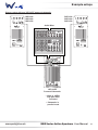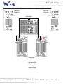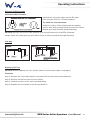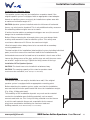
1
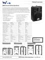
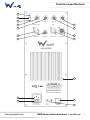
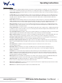
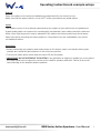
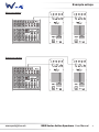
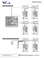
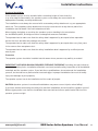
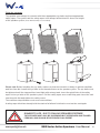
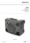
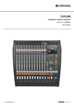
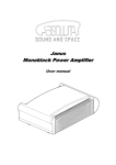
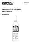
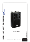
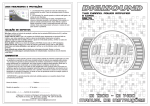
DSR Series
Active Speakers
User Manual
Order codes:
SPEA34 - DSR 10A
SPEA35 - DSR 12A
SPEA36 - DSR 15A
Safety advice
WARNING
FOR YOUR OWN SAFETY, PLEASE READ THIS USER MANUAL
CAREFULLY BEFORE YOUR INITIAL START-UP!
• Immediately upon receiving this product, carefully unpack the carton and check the contents to ensure that all the parts are present.
DANGER TO LIFE!
• Before initial start-up, please make sure that there is no damage caused during transportation.
BEFORE OPERATING THE
SPEAKER FOR THE FIRST
• Should there be any damage, consult your dealer and do not use the equipment.
TIME, THE INSTALLATION
• Retain the carton and all packaging materials.
HAS TO BE APPROVED
BY AN EXPORT
• In the event that the equipment must be returned to the supplier, it is important that the equipment is returned in the original carton and packaging.
• To maintain the equipment in good working condition and to ensure safe operation, it is necessary for the user to follow the safety instructions and warning notes written in this manual.
• Please note that damages caused by user modifications to this equipment are not subject to warranty.
CAUTION!
KEEP THIS EQUIPMENT
AWAY FROM MOISTURE,
RAIN AND LIQUIDS, AND
OUT OF DAMP/HUMID
ENVIRONMENTS
CAUTION!
TAKE CARE USING
THIS EQUIPMENT!
HIGH VOLTAGE-RISK
OF ELECTRIC SHOCK!!
IMPORTANT:
The manufacturer will not accept liability for any resulting damages caused by the non-observance
of this manual or any unauthorised modification to the equipment.
• Never let the power cable come into contact with other
cables. Handle the power cable and all mains voltage
connections with caution!
• Never remove warning or informative labels from the
equipment.
• Do not open or modify the equipment.
• Do not connect this equipment to a dimmer-pack.
• Do not switch the equipment on and off in short intervals,
as this will reduce the system’s life.
• Only use the equipment indoors.
• Do not expose to flammable sources, liquids or gases.
• Always disconnect the power from the mains when
equipment is not in use or before cleaning! Only handle
the power cable by the plug. Never pull out the plug by
pulling the power cable.
• Make sure that the available voltage is between 220V/240V.
• Make sure that the power cable is never crimped or damaged. Check the equipment and the power cable periodically.
• If the equipment is dropped or damaged, disconnect
the mains power supply immediately. Have a qualified
engineer inspect the equipment before operating again.
• If the equipment has been exposed to drastic temperature
fluctuation (e.g. after transportation), do not switch it on
immediately. The arising condensation might damage the
equipment. Leave the equipment switched off until it has
reached room temperature.
• If the product fails to function correctly, discontinue use
immediately. Pack securely (preferably in the original
packing material), and return to your dealer for service.
• Only use fuses of same type and rating.
• Repairs, servicing and power connection must only be
carried out by a qualified technician. THIS UNIT CONTAINS
NO USER SERVICEABLE PARTS.
• WARRANTY: One year from date of purchase.
OPERATING DETERMINATIONS
If this equipment is operated in any other way, than those described in this manual, the product may suffer damage and the warranty becomes void. Incorrect operation may lead to danger e.g: short-circuit, burns and electric shocks etc.
Incase of malfunction this device should be returned for service or inspection.
Do not endanger your own safety and the safety of others!
Incorrect installation or use can cause serious damage to people and/or property.
www.prolight.co.uk
DSR Series Active Speakers User Manual
2
Safety advice
Safe installation
Make sure that the area below the installation place is blocked when rigging, derigging or servicing the system. Please note: W Audio cannot be made liable for damages caused by incorrect installations
and excessive noise levels.
Unpacking and transportation:
Unpack the units and examine them for transport damage.
When boxed in the original packaging the speaker system should be carried by two persons of the same size. Carrying the speaker system with one person alone should be avoided as the heavy weight
and strain could lead to back injury. Please note that all speaker systems weighing more than 25kg
must be transported by two persons.
DANGER TO LIFE!
A FALLING SPEAKER SYSTEM CAN
CAUSE DEADLY ACCIDENTS, ALL SAFETY
INSTRUCTIONS GIVEN IN THIS MANUAL
MUST BE OBSERVED.
CAUTION - FIRE HAZARD!
KEEP AWAY FROM CIGARETTES,
FIRE AND HEATERS ETC. TREAT THE
SURFACE WITH A FIRE RETARDANT
AT REGULAR INTERVALS.
DANGER!
IMPACT HAZARD
SECONDARY ATTACHMENT
REQUIRED FOR OVERHEAD
INSTALLATION!
DANGER TO LIFE DUE
TO FALLING SPEAKER
SYSTEMS.
WARNING!
LOUD NOISE HAZARD
EAR PROTECTION
MUST BE WORN
Please note that speaker systems can move due to bass beats and vibrations. Furthermore, unintended pushing on the speakers present a further risk. The speaker system must always be secured against moving or the respective area has to be blocked.
www.prolight.co.uk
DSR Series Active Speakers User Manual
3
Product overview
DSR Series Active Speakers
The DSR series offers superior sound and has features that until now have
only been found on more expensive equipment. Safe and easy installation
is possible by multiple rigging points and functional casing design gives true
multifunction capability without compromise. The DSR Range feature VariFlare;
a rotatable top end horn flare. This feature allows an installer to tailor the HF
dispersion to the application making the DSR range ideal as a foldback monitor
or horizontal installation cabinet.
•High impact molded polypropylene enclosure
•Heavy duty dynamic switch mode
power supply
•Built-in highly efficient class D (LF) + AB (HF) amplifiers
•10", 12", 15" low-mid
frequency transducers
•1" compression high frequency driver
•80° x 60° coverage pattern
•Smooth response with high power
•5 integral suspension points
•Integral 35mm top hat for optional pole mounting
•Optional padded transit covers available
Specifications
DSR 10A
DSR 12A
DSR 15A
Frequency range (-10dB)
60Hz~19kHz
56Hz~19kHz
45Hz~19kHz
Frequency response (-3dB)
70Hz~19kHz
65Hz~19kHz
55Hz~19kHz
High pass frequency
40Hz
40Hz
40Hz
Maximum calculated SPL
123dB
125dB
127dB
Horizontal coverage
80°
80°
80°
Vertical coverage
60°
60°
60°
Max. system power
700W
900W
1000W
Amplifier power LF
300Wrms
400Wrms
450Wrms
Amplifier power HF
50Wrms
50Wrms
50Wrms
LF transducer
10"/50mm
12"/50mm
15"/65mm
HF transducer
1"/25mm
1"/25mm
1"/25mm
Crossover frequency
2.5kHz
2.2kHz
2.2kHz
Loop/mix out
XLR/M balanced
XLR/M balanced
XLR/M balanced
AC input
220-240V~50/60Hz
220-240V~50/60Hz
220-240V~50/60Hz
Fuse rating
T4A 250V
T4A 250V
T4A 250V
Dimensions (H x W x D)
557 x 332 x 313mm
615 x 416 x 356mm
740 x 475 x 400mm
Weight
14.5kg
17kg
22.5kg
Order code
SPEA34
SPEA35
SPEA36
DSR10A dimensions
DSR12A dimensions
DSR15A dimensions
475mm
416mm
400mm
356mm
www.prolight.co.uk
DSR Series Active Speakers User Manual
740mm
615mm
313mm
557mm
332mm
In the box: 1 x active speaker,
1 x IEC power cable
& 1 x user manual
4
Technical specifications
LIMIT
01
0
HF
02
04
0
0
LF
-10
03
0
POWER ON
+10
BASS
-10
+10
-10
TREBLE
+10
-10
LINE VOL
MICROPHONE
+10
MASTER VOL
06
LINE
05
07
0
08
-10
MIC INPUT
+10
LINE INPUT
MIC VOL
MIX OUTPUT
09
11
10
DSR SERIES
12
CAUTION
RISK OF ELECTRIC SHOCK
DO NOT OPEN
CAUTION: TO PREVENT ELECTRIC SHOCK DO NOT REMOVE
TOP OR BOTTOM COVERS. NO USER SERVICABLE PARTS INSIDE
WARNING: TO REDUCE THE RISK OF FIRE OR ELECTRIC SHOCK.
DO NOT EXPOSE THIS EQUIPMENT TO RAIN OR MOISTURE
13
MAINS INPUT
AC 230V 50/60Hz
www.prolight.co.uk
I
I
O
FUSE
T4A/250V
POWER
I
16
ONLY USE WITH A 250V FUSE
15
14
DSR Series Active Speakers User Manual
5
Operating instructions
Satellite speaker:
1
HF Limit LED: The HF Limit LED illuminates yellow when the HF amplifier is beginning to clip. The LED indicates
to the user the amplifiers limit has been reached, the overall system gain or the HF gain should be reduced
until the LED ceases to illuminate. Failure to observe the instruction may result in component failure within the
loudspeaker enclosure.
2
LF Limit LED: The LF Limit LED illuminates red when the LF amplifier is beginning to clip. The LED indicates to
the user the amplifiers limit has been reached, the overall system gain or the LF gain should be reduced until
the LED ceases to illuminate. Failure to observe the instruction may result in component failure within the
loudspeaker enclosure.
3
Active LED: This LED illuminates when the unit is switched on and ready for use. Should the LED fail illuminate
please carefully check the mains voltage supply and mains inlet fuse, if the main supply and fuse have been
verified and the unit does not show active please consult you’re W Audio dealer for advice and service.
4
Bass (LF) Control: The bass response for the DSR-A loudspeaker can be adjusted by +- 10dB. During normal
operation the bass control should be set to the centre (0) position and then adjusted in small amounts to suit
the room acoustics or musical content.
5
Treble (HF) Control: The treble response for the DSR-A loudspeaker can be adjusted by +- 10dB. During normal
operation the treble control should be set to the centre (0) position and then adjusted in small amounts to suit
the room acoustics or musical content.
6
Line Input Gain Control: Input gain control for the balanced XLR line level signal input. Before connecting signal
cables the gain control should be turned fully clockwise. Turn clockwise to increase input gain.
7
Master Volume Control: Volume (level) control for the DSR-A loudspeaker. Before connecting signal cables the
Volume control should be turned fully clockwise. Turn clockwise to increase loudspeaker output level.
8
Microphone (MIC) Input: Balanced XLR microphone level input suitable for use with dynamic microphones or
condenser microphones with the use of an external +48V phantom power supply.
9
Microphone (MIC) Input Gain Control: Input gain control for the balanced XLR microphone level signal input.
Before connecting signal cables the gain control should be turned fully clockwise. Turn clockwise to increase
input gain.
10
Line Input: Balanced XLR line level input suitable for input for connection to line level sources such as mixing consoles.
11
MIX output: Balanced XLR line level output, the MIX output is a combined signal containing both the XLR line input and also the XLR microphone input. This output can be used to link signal to additional DSR-A loudspeakers.
12
Heat Sink: The heat sink assembly dissipates heat generated by the internal amplifier modules, to ensure
reliable operation the heat sink assembly should be kept clear of dust, dirt or any obstructions. If using the
DSR-A loudspeaker inside a padded bag care should be taken to ensure the free flow of air around the heat
sink assembly by opening the rear flap.
13
Mains Input: Connect the DSR-A Loudspeaker to the mains outlet using the supplied 13A BS1363 IEC power
cord. Care should be taken to ensure the mains outlet voltage is 220-240Vac 50~60Hz.
14
Earth Connection: The DSR-A loudspeaker is a Class1 product designed to be earthed at all times. Do not remove or tamper with the protective earth connection.
15
Mains Power Switch: Mains power on/off for the system. Connections for signal input/output should be made
before the loudspeaker is powered on.
16
Mains Fuse: The DSR-A loudspeaker features a fused IEC mains inlet.
www.prolight.co.uk
DSR Series Active Speakers User Manual
6
Operating instructions & example setups
Start Up
Place the speaker to the desired installation area and carefully turn it onto its feet.
Make sure that the power switch is set to “OFF” before you connect any audio cables.
Inputs
This speaker system is to be directly connected to the outputs of your audio mixer or keyboard etc.
A good quality cable run improves the sound quality considerably. Input cables should be short and
direct, since high frequencies may be absorbed if the cables are unnecessarily long. Also a longer cable may lead to humming and noise problems. If long cables runs are unavoidable, you should use balanced cables.
Connection
• Before connecting the speakers and audio source to this device, make sure that all volume/gain
controls are turned fully anti-clockwise in the minimum position.
• Turn on the mains power switch and the mains LED will illuminate.
• IMPORTANT! DO NOT OVERDRIVE THE SYSTEM. If any distortion or clipping is audible you must reduce
the input signal level or reduce the volume of the satellite speakers and bass. Failure to do so will
cause damage to the amplifier and or speakers.
www.prolight.co.uk
DSR Series Active Speakers User Manual
7
Example setups
Mono two speaker
LIMIT
LIMIT
0
HF
0
0
0
HF
0
LF
0
0
0
LF
-10
POWER ON
+10
BASS
-10
+10
-10
TREBLE
+10
-10
LINE VOL
MICROPHONE
-10
+10
MASTER VOL
POWER ON
LINE
+10
BASS
-10
MIC INPUT
-10
TREBLE
-10
+10
MASTER VOL
LINE
0
+10
-10
LINE INPUT
MIC VOL
MIX OUTPUT
MIC INPUT
DSR SERIES
+10
LINE INPUT
MIC VOL
MIX OUTPUT
DSR SERIES
CAUTION
CAUTION
RISK OF ELECTRIC SHOCK
DO NOT OPEN
RISK OF ELECTRIC SHOCK
DO NOT OPEN
CAUTION: TO PREVENT ELECTRIC SHOCK DO NOT REMOVE
TOP OR BOTTOM COVERS. NO USER SERVICABLE PARTS INSIDE
CAUTION: TO PREVENT ELECTRIC SHOCK DO NOT REMOVE
TOP OR BOTTOM COVERS. NO USER SERVICABLE PARTS INSIDE
WARNING: TO REDUCE THE RISK OF FIRE OR ELECTRIC SHOCK.
WARNING: TO REDUCE THE RISK OF FIRE OR ELECTRIC SHOCK.
DO NOT EXPOSE THIS EQUIPMENT TO RAIN OR MOISTURE
DO NOT EXPOSE THIS EQUIPMENT TO RAIN OR MOISTURE
I
I
I
O
FUSE
T4A/250V
POWER
I
O
POWER
I
I
FUSE
T4A/250V
ONLY USE WITH A 250V FUSE
MAINS INPUT
AC 230V 50/60Hz
+10
LINE VOL
MICROPHONE
0
-10
MONO SUM
+10
ONLY USE WITH A 250V FUSE
MAINS INPUT
AC 230V 50/60Hz
Stereo two speaker
LIMIT
LIMIT
0
HF
0
0
0
HF
0
LF
0
0
POWER ON
+10
BASS
-10
+10
-10
TREBLE
+10
-10
LINE VOL
MICROPHONE
-10
+10
MASTER VOL
LINE
POWER ON
+10
BASS
-10
MIC INPUT
+10
-10
TREBLE
+10
MASTER VOL
LINE
-10
LINE INPUT
MIC VOL
MIX OUTPUT
MIC INPUT
+10
LINE INPUT
MIC VOL
MIX OUTPUT
DSR SERIES
CAUTION
CAUTION
RISK OF ELECTRIC SHOCK
DO NOT OPEN
RISK OF ELECTRIC SHOCK
DO NOT OPEN
CAUTION: TO PREVENT ELECTRIC SHOCK DO NOT REMOVE
TOP OR BOTTOM COVERS. NO USER SERVICABLE PARTS INSIDE
CAUTION: TO PREVENT ELECTRIC SHOCK DO NOT REMOVE
TOP OR BOTTOM COVERS. NO USER SERVICABLE PARTS INSIDE
WARNING: TO REDUCE THE RISK OF FIRE OR ELECTRIC SHOCK.
WARNING: TO REDUCE THE RISK OF FIRE OR ELECTRIC SHOCK.
DO NOT EXPOSE THIS EQUIPMENT TO RAIN OR MOISTURE
DO NOT EXPOSE THIS EQUIPMENT TO RAIN OR MOISTURE
O
POWER
ONLY USE WITH A 250V FUSE
MAINS INPUT
AC 230V 50/60Hz
I
I
O
FUSE
T4A/250V
POWER
I
I
I
FUSE
T4A/250V
I
ONLY USE WITH A 250V FUSE
-10
0
+10
DSR SERIES
MAINS INPUT
AC 230V 50/60Hz
+10
LINE VOL
MICROPHONE
0
-10
www.prolight.co.uk
0
LF
-10
DSR Series Active Speakers User Manual
8
Example setups
Four speaker stereo system
LIMIT
LIMIT
0
HF
0
0
0
HF
0
LF
0
0
+10
BASS
POWER ON
-10
+10
-10
TREBLE
+10
-10
LINE VOL
MICROPHONE
-10
+10
MASTER VOL
+10
BASS
POWER ON
LINE
-10
+10
-10
TREBLE
-10
+10
MASTER VOL
LINE
0
+10
-10
LINE INPUT
MIC VOL
MIX OUTPUT
MIC INPUT
DSR SERIES
+10
LINE INPUT
MIC VOL
CAUTION
RISK OF ELECTRIC SHOCK
DO NOT OPEN
RISK OF ELECTRIC SHOCK
DO NOT OPEN
CAUTION: TO PREVENT ELECTRIC SHOCK DO NOT REMOVE
TOP OR BOTTOM COVERS. NO USER SERVICABLE PARTS INSIDE
CAUTION: TO PREVENT ELECTRIC SHOCK DO NOT REMOVE
TOP OR BOTTOM COVERS. NO USER SERVICABLE PARTS INSIDE
WARNING: TO REDUCE THE RISK OF FIRE OR ELECTRIC SHOCK.
WARNING: TO REDUCE THE RISK OF FIRE OR ELECTRIC SHOCK.
DO NOT EXPOSE THIS EQUIPMENT TO RAIN OR MOISTURE
DO NOT EXPOSE THIS EQUIPMENT TO RAIN OR MOISTURE
I
I
I
O
FUSE
T4A/250V
POWER
I
O
POWER
I
I
FUSE
T4A/250V
ONLY USE WITH A 250V FUSE
MIX OUTPUT
DSR SERIES
CAUTION
MAINS INPUT
AC 230V 50/60Hz
+10
LINE VOL
MICROPHONE
0
-10
MIC INPUT
ONLY USE WITH A 250V FUSE
MAINS INPUT
AC 230V 50/60Hz
LIMIT
LIMIT
0
HF
0
0
0
HF
0
LF
0
0
0
LF
-10
+10
BASS
POWER ON
-10
+10
-10
TREBLE
+10
-10
LINE VOL
MICROPHONE
-10
+10
MASTER VOL
POWER ON
LINE
+10
BASS
-10
+10
-10
TREBLE
-10
+10
MASTER VOL
LINE
0
+10
-10
LINE INPUT
MIC VOL
MIX OUTPUT
MIC INPUT
DSR SERIES
+10
LINE INPUT
MIC VOL
CAUTION
RISK OF ELECTRIC SHOCK
DO NOT OPEN
RISK OF ELECTRIC SHOCK
DO NOT OPEN
CAUTION: TO PREVENT ELECTRIC SHOCK DO NOT REMOVE
TOP OR BOTTOM COVERS. NO USER SERVICABLE PARTS INSIDE
CAUTION: TO PREVENT ELECTRIC SHOCK DO NOT REMOVE
TOP OR BOTTOM COVERS. NO USER SERVICABLE PARTS INSIDE
WARNING: TO REDUCE THE RISK OF FIRE OR ELECTRIC SHOCK.
WARNING: TO REDUCE THE RISK OF FIRE OR ELECTRIC SHOCK.
DO NOT EXPOSE THIS EQUIPMENT TO RAIN OR MOISTURE
DO NOT EXPOSE THIS EQUIPMENT TO RAIN OR MOISTURE
I
I
I
O
FUSE
T4A/250V
POWER
I
O
POWER
I
I
FUSE
T4A/250V
ONLY USE WITH A 250V FUSE
MIX OUTPUT
DSR SERIES
CAUTION
MAINS INPUT
AC 230V 50/60Hz
+10
LINE VOL
MICROPHONE
0
-10
MIC INPUT
Common standalone mono speaker system
0
LF
-10
ONLY USE WITH A 250V FUSE
MAINS INPUT
AC 230V 50/60Hz
LIMIT
LIMIT
0
HF
0
0
0
HF
0
LF
0
0
0
LF
-10
POWER ON
+10
BASS
-10
+10
-10
TREBLE
+10
-10
LINE VOL
MICROPHONE
-10
+10
MASTER VOL
LINE
POWER ON
+10
BASS
-10
-10
TREBLE
+10
-10
LINE VOL
MICROPHONE
+10
MASTER VOL
LINE
0
-10
MIC INPUT
+10
0
+10
-10
LINE INPUT
MIC VOL
MIX OUTPUT
MIC INPUT
DSR SERIES
+10
LINE INPUT
MIC VOL
MIX OUTPUT
DSR SERIES
iPod or other
line level source
Microphone
source
CAUTION
RISK OF ELECTRIC SHOCK
DO NOT OPEN
CAUTION: TO PREVENT ELECTRIC SHOCK DO NOT REMOVE
TOP OR BOTTOM COVERS. NO USER SERVICABLE PARTS INSIDE
WARNING: TO REDUCE THE RISK OF FIRE OR ELECTRIC SHOCK.
WARNING: TO REDUCE THE RISK OF FIRE OR ELECTRIC SHOCK.
DO NOT EXPOSE THIS EQUIPMENT TO RAIN OR MOISTURE
DO NOT EXPOSE THIS EQUIPMENT TO RAIN OR MOISTURE
www.prolight.co.uk
O
POWER
ONLY USE WITH A 250V FUSE
MAINS INPUT
AC 230V 50/60Hz
I
I
O
FUSE
T4A/250V
POWER
I
I
I
FUSE
T4A/250V
I
ONLY USE WITH A 250V FUSE
MAINS INPUT
AC 230V 50/60Hz
CAUTION
RISK OF ELECTRIC SHOCK
DO NOT OPEN
CAUTION: TO PREVENT ELECTRIC SHOCK DO NOT REMOVE
TOP OR BOTTOM COVERS. NO USER SERVICABLE PARTS INSIDE
DSR Series Active Speakers User Manual
9
Example setups
Stereo system with one LSR 115P powered subwoofer
LIMIT
0
HF
0
0
0
LF
-10
POWER ON
+10
BASS
-10
+10
-10
TREBLE
+10
-10
LINE VOL
MICROPHONE
+10
MASTER VOL
LINE
0
-10
MIC INPUT
DSR 10A
DSR 12A
DSR 15A
DSR 10A
DSR 12A
DSR 15A
LIMIT
0
HF
0
-10
POWER ON
+10
BASS
-10
MIX OUTPUT
-10
0
+10
-10
LINE VOL
+10
MASTER VOL
LINE
0
-10
LINE INPUT
+10
TREBLE
MICROPHONE
+10
MIC VOL
0
LF
MIC INPUT
+10
LINE INPUT
MIC VOL
MIX OUTPUT
Audio Mixer
DSR SERIES
DSR SERIES
CAUTION
RISK OF ELECTRIC SHOCK
DO NOT OPEN
CAUTION: TO PREVENT ELECTRIC SHOCK DO NOT REMOVE
TOP OR BOTTOM COVERS. NO USER SERVICABLE PARTS INSIDE
WARNING: TO REDUCE THE RISK OF FIRE OR ELECTRIC SHOCK.
WARNING: TO REDUCE THE RISK OF FIRE OR ELECTRIC SHOCK.
DO NOT EXPOSE THIS EQUIPMENT TO RAIN OR MOISTURE
DO NOT EXPOSE THIS EQUIPMENT TO RAIN OR MOISTURE
O
POWER
ONLY USE WITH A 250V FUSE
MAINS INPUT
AC 230V 50/60Hz
I
I
O
FUSE
T4A/250V
POWER
I
I
I
FUSE
T4A/250V
I
ONLY USE WITH A 250V FUSE
MAINS INPUT
AC 230V 50/60Hz
CAUTION
RISK OF ELECTRIC SHOCK
DO NOT OPEN
CAUTION: TO PREVENT ELECTRIC SHOCK DO NOT REMOVE
TOP OR BOTTOM COVERS. NO USER SERVICABLE PARTS INSIDE
LSR 115P
Powered Subwoofer
• 80Hz or 125Hz
high pass filter
activated
• Subwoofer in
parallel mode
www.prolight.co.uk
DSR Series Active Speakers User Manual
10
Example setups
Stereo system with two LSR 115P powered subwoofers & two active mid/high cabinets
LIMIT
0
HF
0
0
0
LF
-10
POWER ON
+10
BASS
-10
+10
-10
TREBLE
+10
-10
LINE VOL
MICROPHONE
+10
MASTER VOL
DSR 12A
DSR 15A
DSR 12A
DSR 15A
LINE
LIMIT
0
HF
0
-10
POWER ON
+10
BASS
-10
+10
-10
TREBLE
0
+10
-10
LINE VOL
MICROPHONE
+10
MASTER VOL
LINE
0
-10
MIC INPUT
0
LF
0
+10
-10
LINE INPUT
MIC VOL
MIX OUTPUT
MIC INPUT
+10
LINE INPUT
MIC VOL
MIX OUTPUT
Audio Mixer
DSR SERIES
DSR SERIES
CAUTION
RISK OF ELECTRIC SHOCK
DO NOT OPEN
CAUTION: TO PREVENT ELECTRIC SHOCK DO NOT REMOVE
TOP OR BOTTOM COVERS. NO USER SERVICABLE PARTS INSIDE
WARNING: TO REDUCE THE RISK OF FIRE OR ELECTRIC SHOCK.
WARNING: TO REDUCE THE RISK OF FIRE OR ELECTRIC SHOCK.
DO NOT EXPOSE THIS EQUIPMENT TO RAIN OR MOISTURE
DO NOT EXPOSE THIS EQUIPMENT TO RAIN OR MOISTURE
O
POWER
ONLY USE WITH A 250V FUSE
MAINS INPUT
AC 230V 50/60Hz
I
I
O
FUSE
T4A/250V
POWER
I
I
I
FUSE
T4A/250V
I
ONLY USE WITH A 250V FUSE
MAINS INPUT
AC 230V 50/60Hz
CAUTION
RISK OF ELECTRIC SHOCK
DO NOT OPEN
CAUTION: TO PREVENT ELECTRIC SHOCK DO NOT REMOVE
TOP OR BOTTOM COVERS. NO USER SERVICABLE PARTS INSIDE
LSR 115P
Powered Subwoofer
• 80Hz or 125Hz
high pass filter
activated
• Subwoofer in
parallel mode
www.prolight.co.uk
DSR Series Active Speakers User Manual
11
Operating instructions
Balanced XLR Connection
Connection With The Mains
Connect the unit to the mains via the IEC mains inlet using the 13A UK - IEC cord supplied.
The earth has to be connected.
Switch the unit on. After switching on the speaker
system, wait 8-10 seconds before you turn the volume
control up in order to avoid speaker damage.
CAUTION! Increase the level of each channel up to the point where the clip LEDs illuminate.
Always check the sound pressure level with a meter in order to keep to the legal threshold.
Jack plug
Replacing The Fuse
CAUTION! Before replacing the fuse, please make sure that mains cable is unplugged.
Procedure
Step 1: Unscrew the fuse holder and the rear panel with a screw driver (anti-clockwise).
Step 2: Remove the old fuse from the fuse holder.
Step 3: Install a new fuse of the same type and rating.
Step 4: Replace the fuse holder in the housing and fix it.
www.prolight.co.uk
DSR Series Active Speakers User Manual
12
Installation instructions
Installation on a Speaker Stand
The speaker system may only be installed on a speaker stand if the original speaker system is equipped with an appropriate stand adaptor.
Stands or satellite systems must only be installed on a plane area with a maximum inclination angle of 5°.
CAUTION: Speaker systems installed under the influence of horizontal forces, e.g. wind, can be impaired. This is why additional safety measures like attaching ballast weights have to be taken.
If inclined tension cables or prolonged outriggers are used, the area of danger has to marked or blocked.
Before lifting or lowering the telescopic tubes, you must always block a safety area around the stand or satellite system. This safety area must have a diameter of 1.5 times the maximum height.
Lifted telescopic tubes always have to be secured with a secondary securing attachment.
The total weight of the installation (total weight of system including individual parts) must never exceed the maximum load of the installation area.
Unintended movement of the load has to be avoided - also in case of fire!
Loosen the fixing screws of the legs, pull the legs out until the cross struts are at a 90˚ angle to the legs. Tighten the fixing screws of the legs.
Installation Of The Speaker System
CAUTION: The loads have to be installed in a balanced way.
CAUTION: The carrying capacity of the stand or speaker stand must never be exceeded. (Note: Stand/s not included)
Wall Installation
The speaker system can only be installed on a wall, if the original speaker system is equipped with an appropriate mounting point.
Before attaching the speaker system, make sure that the installation area can hold a minimum point load of 10 times the installations weight. (E.g. 13kg - 130kg point load).
The durability of the installation depends very much on the material used at the installation area (building material), such as wood, concrete and brick etc. This is why the fixing material must be chosen to suit the wall material. Always ask a specialist for the correct plug/screw combination indicating the maximum load and building material. (Note: Wall bracket/s not included)
www.prolight.co.uk
DSR Series Active Speakers User Manual
13
Installation instructions
Overhead Installation
If the speaker system is to be installed with a mounting height of more than 1m (e.g. on a stage or framework), the speaker system must always be secured with an appropriate secondary securing attachment.
The installation must always be secured with a secondary safety attachment. e.g. an appropriate catch net. The secondary safety attachment must be constructed in a way that no part of the installation can fall down if the main attachment fails.
When rigging, derigging, or servicing the speaker system standing in the area below the installation place, on bridges or other endangered areas are forbidden.
The operator has to make sure that the safety data is approved by an expert before operation for the first time and after any changes are made.
The operator has to make sure that the safety data is approved by an expert after every four years in the course of an acceptance test.
The operator has to make sure that the safety installation data is approved by a skilled person once a year.
Procedure
The speaker system should be installed outside areas where persons may walk by or seated.
IMPORTANT! OVER HEAD RIGGING REQUIRES EXTENSIVE EXPERIENCE including (but not limited to)
calculating working limits, installation materials used, and periodic safety inspection of all installation
materials and the speaker system. If you lack these qualifications, do not attempt the installation
yourself, but instead use a professional structural rigger. Improper installation can result in bodily injury and damage to your property.
The speaker system has to be installed out of the reach of people.
CAUTION: Speaker systems in overhead installations may cause severe injuries when falling! If you have doubts concerning the safety of a possible installation, do not install the speaker system!
Before rigging make sure that the installation area can hold a minimum point load of 10 times the
speaker systems weight.
www.prolight.co.uk
DSR Series Active Speakers User Manual
14
Flying the speakers
The speaker must always be secured with three appropriate eye bolts and three appropriate safety ropes. The eyelets and the safety ropes must always hold at least 12 times the weight of the speaker system. (Note: Wall bracket/s not included)
Please note: Before installing the eye bolts, make sure that the thread is is always in perfect condition
and free from dirt. Install the eye bolts in the threaded holes on the speaker system. The eye bolts must
be tightened until the stop position, hand tight with out any tools. Insert the quick links of the safety
ropes in the eye bolts of the speaker system. Pull the safety ropes over a safe fixing spot. Insert the end
into the quick link and tighten the safety screw.
The maximum drop distance must never exceed 20cm.
A safety rope which has already held the strain of a fall and is defective must not be used again.
DANGER TO LIFE - DUE TO FALLING SPEAKERS SYSTEMS!
THE SPEAKER MUST ONLY BE SUSPENDED BY EXPERIENCED AND TRAINED
PERSONS, AND SHOULD BE APPROVED BY AN EXPERT
www.prolight.co.uk
DSR Series Active Speakers User Manual
15
WEEE notice
Correct Disposal of this Product
(Waste Electrical & Electronic Equipment)
(Applicable in the European Union and other European countries
with separate collection systems)
This marking shown on the product or its literature, indicates that it should not be disposed with other household wastes at the end of its working life. To prevent possible harm to the environment or human health from uncontrolled waste disposal, please separate this from other
types of wastes and recycle it responsibly to promote the sustainable reuse of material resources.
Household users should contact either the retailer where they purchased this product, or their
local government office, for details of where and how they can take this item for environmentally
safe recycling.
Business users should contact their supplier and check the terms and conditions of the purchase contract. This product should not be mixed with other commercial wastes for disposal.
www.prolight.co.uk
DSR Series Active Speakers User Manual
16