1
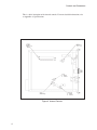
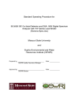
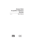
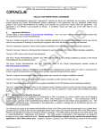
Model 3106D
HV Power Supply
User’s Manual
9231583A
Copyright 2004, Canberra Industries, Inc. All rights reserved.
The material in this document, including all information, pictures,
graphics and text, is the property of Canberra Industries, Inc. and
is protected by U.S. copyright laws and international copyright
conventions.
Canberra expressly grants the purchaser of this product the right
to copy any material in this document for the purchaser’s own use,
including as part of a submission to regulatory or legal authorities
pursuant to the purchaser’s legitimate business needs.
No material in this document may be copied by any third party, or
used for any commercial purpose, or for any use other than that
granted to the purchaser, without the written permission of
Canberra Industries, Inc.
Canberra Industries, 800 Research Parkway, Meriden, CT 06450
Tel: 203-238-2351 FAX: 203-235-1347 http://www.canberra.com
The information in this document describes the product as
accurately as possible, but is subject to change without notice.
Printed in the United States of America.
Table of Contents
1. Introduction . . . . . . . . . . . . . . . . . . . . . . . . . . . . . 1
2. Controls and Connectors . . . . . . . . . . . . . . . . . . . . . . 2
3. Operating Instructions . . . . . . . . . . . . . . . . . . . . . . . 5
Installation . . . . . . . . . . . . . . . . . . . . . . . . . . . . . . . . . . . . . . . . . . . . . . 5
Internal Controls. . . . . . . . . . . . . . . . . . . . . . . . . . . . . . . . . . . . . . . . . . . 5
Polarity Selection . . . . . . . . . . . . . . . . . . . . . . . . . . . . . . . . . . . . . . . . 6
J4, Brightness Control. . . . . . . . . . . . . . . . . . . . . . . . . . . . . . . . . . . . . . 6
Inhibit Control. . . . . . . . . . . . . . . . . . . . . . . . . . . . . . . . . . . . . . . . . . 6
Automatic Overload Shutdown . . . . . . . . . . . . . . . . . . . . . . . . . . . . . . . . . 7
Setup. . . . . . . . . . . . . . . . . . . . . . . . . . . . . . . . . . . . . . . . . . . . . . . . . 7
Divide By 10 Output . . . . . . . . . . . . . . . . . . . . . . . . . . . . . . . . . . . . . . . . 7
Preventive Maintenance . . . . . . . . . . . . . . . . . . . . . . . . . . . . . . . . . . . . . . . 8
4. Circuit Description. . . . . . . . . . . . . . . . . . . . . . . . . . 9
A. Specifications . . . . . . . . . . . . . . . . . . . . . . . . . . . 10
Inputs . . . . . . . . . . . . . . . . . . . . . . . . . . . . . . . . . . . . . . . . . . . . . . . . 10
Outputs . . . . . . . . . . . . . . . . . . . . . . . . . . . . . . . . . . . . . . . . . . . . . . . 10
Controls . . . . . . . . . . . . . . . . . . . . . . . . . . . . . . . . . . . . . . . . . . . . . . 10
Indicators . . . . . . . . . . . . . . . . . . . . . . . . . . . . . . . . . . . . . . . . . . . . . . 10
Performance . . . . . . . . . . . . . . . . . . . . . . . . . . . . . . . . . . . . . . . . . . . . 11
Connectors . . . . . . . . . . . . . . . . . . . . . . . . . . . . . . . . . . . . . . . . . . . . . 11
Power Requirements . . . . . . . . . . . . . . . . . . . . . . . . . . . . . . . . . . . . . . . . 12
Physical . . . . . . . . . . . . . . . . . . . . . . . . . . . . . . . . . . . . . . . . . . . . . . 12
Environmental . . . . . . . . . . . . . . . . . . . . . . . . . . . . . . . . . . . . . . . . . . . 12
B. Installation Considerations . . . . . . . . . . . . . . . . . . . . 13
Notes
ii
1. Introduction
The Canberra Model 3106D is a NIM high voltage power supply designed primarily
for operation with semiconductor detectors. It is particularly well suited for use with
high resolution detector systems. By design, the 3106D will accommodate all types of
detectors requiring up to 6 kV bias and up to 300 µA of current.
The output voltage is continuously adjustable from ±30 V dc to ±6000 V dc. For low
voltage detectors, a secondary output having a range of ±3 V to ±600 V is available. A
three-digit voltmeter measures and displays the output voltage with a resolution of 10
volts on the normal output and 1 volt on the secondary output. Polarity is selected internally.
The Model 3106D will withstand any overload or short circuit condition for an indefinite period of time. An inhibit input is available for remote shut down of the 3106D.
The unit can be programmed by an internal jumper either to resume normal operation
after removal of the fault or the inhibit or to require a manual reset.
The 3106D’s output rise time of five seconds protects preamplifiers and detectors from
excessive surge currents while charging.
Controls and Connectors
2. Controls and Connectors
This is a brief description of the front panel controls and connectors. For more detailed
information, refer to Appendix A, Specifications.
Figure 1 Front Panel Controls
2
This is a brief description of the rear panel connectors. For more detailed information,
refer to Appendix A, Specifications.
Figure 2 Rear Panel Controls
3
Controls and Connectors
This is a brief description of the internal controls. For more detailed information, refer
to Appendix A, Specifications.
Figure 3 Internal Controls
4
Installation
3. Operating Instructions
The Model 3106D is factory set for positive output polarity. If negative polarity is required, change the internal polarity board before installing the unit in the NIM bin (refer to the Internal Conrols section, below, for instructions).
Installation
The Canberra Model 2000 NIM bin and Power Supply or equivalent power supply
conforming to DOE/ER-00457T will accommodate the Model 3106D. The right side
cover of the unit acts as a guide for insertion of the unit. Secure the module in place by
turning the two front panel captive screws clockwise until finger tight. It is recommended that the NIM bin power switch be OFF whenever any module is installed or
removed.
The Model 3106D can be safely operated where the ambient air temperature is between 0 °C and +50 °C. Perforations in the top and bottom of the unit’s frame permit
cooling air to circulate through the module. When rack mounted along with other heat
generating equipment, be sure to provide adequate clearance for a flow of cooling air
through the NIM bin.compliant grounding and safety precautions for any internal
power distribution
Internal Controls
Remove the unit’s left side cover to change the internal controls. Figure 3 shows the
position of the internal controls.
WARNING
The Model 3106D generates hazardous high voltage,
which will be present for several minutes after the unit is
switched off.
Before removing the unit from the NIM bin, set the VOLTAGE control to 0.00 volts
and the HV ON/OFF switch to OFF.
Avoid the risk of injury. Leave the unit in the NIM bin until the voltage reduces to 0
volts, as indicated on the front panel digital display.
5
Operating Instructions
Polarity Selection
Output polarity can be changed by removing the unit’s left side cover and changing
the polarity selector board’s location. The board is symmetrical by design. Polarity is
not affected by orientation. When the unit’s NIM bin power is turned on, the front
panel POLARITY preview LEDs will indicate the current polarity selection. Canberra
recommends that the polarity selection be verified before turning on the unit’s NIM
bin power. Factory set to POSitive.
J4, Brightness Control
Jumper J4 sets the display brightness to HIgh or LOw (factory set to low). In the HI
position, the display is at its brightest, but the unit will draw significantly more current. See the Power Requirements specification in Appendix A for details.
Inhibit Control
The Inhibit Function, which is independent of the Voltage Control’s setting, allows the
output voltage to be conditionally turned off or latched off by grounding or by apply ing a logic 0 (≤0.7 V) to the rear panel INHIBIT connector. The front panel INHIBIT
STATUS indicator lights when the output has been inhibited.
Jumper J5
The INHIBIT input is compatible with all Canberra preamps for either position of
Jumper plug J5; it isn’t necessary to set jumper plug J5 to match the HV INHIBIT
logic high level of the associated Canberra preamp.
Jumper J5 selects the pull up/clamp voltage level of the INHIBIT input for compatibility with INHIBIT signals from instruments made by other manufacturers. With J5 in
position 5 (factory setting), the pull up/clamp level is set to +5 volts. With J5 set to position 12 the pull up/clamp level is +12 volts. Please consult the manual provided with
your instrument for its requirements.
Jumper J6
Jumper J6 selects the Latched Inhibit Mode or the Conditional Inhibit Mode.
In the Latched Mode (jumper position A; factory setting), pressing the front panel
RESET button when a logic 1 or open circuit is present at the INHIBIT connector will
restore the output voltage. In the Conditional Mode (jumper position B), an INHIBIT
input of ≥2 V or an open circuit enables the output.
6
Setup
Automatic Overload Shutdown
One of the 3106D’s circuits monitors the output load current and automatically disables the outputs for an overload or a fault condition.
A short duration arc-over or turn-on charging transient will not cause shut down. The
front panel OVERLOAD STATUS indicator lights when the unit has been shut down.
The unit can be programmed to either automatically resume operation when the fault
is removed or to require a manual reset.
Jumper J7
With Jumper J7 in position A (factory setting), the front panel RESET button must be
pressed to resume normal operation after the fault is removed. With Jumper J7 set to
position B, the output will automatically resume when the fault condition is removed.
Setup
After setting the internal controls, install the Model 3106D in the NIM bin. Connect
the load to the appropriate rear panel SHV connector, set the HV ON/OFF switch to
OFF, and set the VOLTAGE control to zero. Set the NIM bin power to ON; the appropriate polarity LED should light, indicating the polarity selected.
Set the HV ON/OFF switch to ON and the VOLTAGE control to the desired setting.
The front panel digital display will indicate the HV OUTPUT voltage in kilovolts
(kV).
Divide By 10 Output
The 3106D has two rear panel output connectors: HV OUTPUT and ÷10 OUTPUT.
Canberra recommends that only one of these outputs be used at a time.
For detectors operating at relatively low bias voltages and requiring little current, the
÷10 output should be used. This output is provided by means of a simple voltage divider network, which has an impedance of 20 megohms. Therefore, loading effects
have to be taken into account if there is a significant current drain.
7
Operating Instructions
The advantage of the ÷10 output is that the zero offset and the control are better by a
factor of 10 over that of the HV OUTPUT. Most detectors (for example, Canberra
PIPS detectors, Si(Li) detectors, and Low Energy (LEGe) detectors), take very little
current and are thus compatible with the ÷10 output. The ÷10 output should never be
used with scintillation detectors which draw relatively large currents.
Preventive Maintenance
Preventive maintenance is not required for this unit.
When needed, the front panel of the unit may be cleaned. Remove power from the unit
before cleaning. Use only a soft cloth dampened with warm water and make sure the
unit is fully dry before restoring power. Because of access holes in the NIM wrap, DO
NOT use any liquids to clean the wrap, side or rear panels.
8
4. Circuit Description
A functional schematic of the Model 3106D can be ordered from Canberra. The high
voltage module is basically a dc to dc converter which converts low voltage dc power
to a high voltage dc output. This output voltage is highly regulated and filtered, and
can be varied by the front panel VOLTAGE control. The input to the high voltage dc
to dc converter is obtained from a conventional NIM power supply and uses ±12 V dc
and ±24 V dc.
An oscillator determines a high frequency (≈37 kHz) at which all amplification, high
voltage transformation, rectification, and filtering occurs. The amplification is a function of a control voltage which performs the functions of control and regulation. A
sample of the output voltage is compared with a reference voltage in the sensing circuit. The sensing circuit generates the control voltage to set and maintain a fixed high
voltage output.
9
Specifications
A. Specifications
Inputs
INPUT POWER – The Model 3106D is powered from a standard NIM Bin and power
supply, such as the Model 2100, 2000 or 1000.
INHIBIT – Logic low or ground inhibits the HV outputs; max logic low ≤0.7 V; logic
high ≥2.0 V or open circuit enables.
Outputs
HV OUTPUT – ±30 to ±6000 V dc, continuously adjustable; 300 µA output current
capability; rear panel SHV connector.
÷10 OUTPUT – ±3 to ±600 V dc, continuously adjustable; Z out = 20 MΩ; rear panel
SHV connector.
Controls
ON/OFF – Front panel toggle switch to enable or disable output.
RESET – Restores normal operation following a latched Inhibit and/or Overload fault
condition.
VOLTAGE – Front panel 10-turn control permits continuous adjustment of the output
voltage.
POLARITY – Internal polarity board sets output polarity.
Indicators
HV OUTPUT – 3-digit panel meter; 0 to 6.00 kV.
POLARITY – Front panel LEDs indicate polarity status continuously.
10
Performance
INHIBIT – LED to indicate Inhibit status.
OVERLOAD – LED to indicate Overload status.
Performance
RIPPLE AND NOISE – ≤3 mV peak to peak at 300 µA.
OUTPUT STABILITY – Long term drift of output voltage is ≤0.01%/hr. and
≤0.02%/8 hr. at constant input line voltage, load, and ambient temperature after a 30
minute warmup.
TEMPERATURE COEFFICIENT – ≤±50 ppm/°C after 30 minute warmup.
REGULATION – ≤0.001% variation in output voltage over the load range and
≤0.001% for ±0.1% input voltage change within the operating range at constant ambient temperature.
OVERLOAD PROTECTION – Power supply will withstand any overload, including a
short circuit for an indefinite period.
CURRENT LIMIT – 450 µA maximum.
DIAL ACCURACY – ±1% of full scale.
METER ACCURACY – ±0.6% of full scale plus 10 volts.
Connectors
HV OUTPUT – Rear panel SHV.
÷10 OUTPUT – Rear panel SHV.
INHIBIT – Rear panel BNC.
11
Specifications
Power Requirements
+24 V – 70 mA
+12 V – 160 mA*
–24 V – 10 mA
–12 V – 150 mA
*With Brightness Control J4 set to HI, +12 V will draw 265 mA, which exceeds the
normal Bin allotment of 167 mA for a single-width module.
Physical
SIZE – Standard single width NIM module 3.43 x 22.12 cm, (1.35 x 8.71 in.) per
DOE/ER-0457T.
NET WEIGHT – 1.4 kg (3.1 lb).
SHIPPING WEIGHT – 2.4 kg (5.3 lb).
Environmental
OPERATING TEMPERATURE – 0 to 50 °C.
OPERATING HUMIDITY – 0-80% relative, non-condensing.
Tested to the environmental conditions specified by EN 61010, Installation Category I,
Pollution Degree 2.
12
B. Installation Considerations
This unit complies with all applicable European Union requirements.
Compliance testing was performed with application configurations commonly used for
this module; i.e. a CE compliant NIM Bin and Power Supply with additional CE compliant application-specific NIM were racked in a floor cabinet to support the module
under test.
During the design and assembly of the module, reasonable precautions were taken by
the manufacturer to minimize the effects of RFI and EMC on the system. However,
care should be taken to maintain full compliance. These considerations include:
• A rack or tabletop enclosure fully closed on all sides with rear door access
• Single point external cable access
• Blank panels to cover open front panel Bin area
• Compliant grounding and safety precautions for any internal power distribution
• The use of CE compliant accessories such as fans, UPS, etc.
Any repairs or maintenance should be performed by a qualified Canberra service
representative. Failure to use exact replacement components, or failure to reassemble
the unit as delivered, may affect the unit’s compliance with the specified EU
requirements.
13
Notes
14
Canberra (we, us, our) warrants to the customer (you, your) that for a period of ninety (90) days from the date of
shipment, software provided by us in connection with equipment manufactured by us shall operate in accordance
with applicable specifications when used with equipment manufactured by us and that the media on which the
software is provided shall be free from defects. We also warrant that (A) equipment manufactured by us shall be
free from defects in materials and workmanship for a period of one (1) year from the date of shipment of such
equipment, and (B) services performed by us in connection with such equipment, such as site supervision and
installation services relating to the equipment, shall be free from defects for a period of one (1) year from the date of
performance of such services.
If defects in materials or workmanship are discovered within the applicable warranty period as set forth above, we
shall, at our option and cost, (A) in the case of defective software or equipment, either repair or replace the
software or equipment, or (B) in the case of defective services, reperform such services.
LIMITATIONS
EXCEPT AS SET FORTH HEREIN, NO OTHER WARRANTIES OR REMEDIES, WHETHER STATUTORY,
WRITTEN, ORAL, EXPRESSED, IMPLIED (INCLUDING WITHOUT LIMITATION, THE WARRANTIES OF
MERCHANTABILITY OR FITNESS FOR A PARTICULAR PURPOSE) OR OTHERWISE, SHALL APPLY. IN NO
EVENT SHALL CANBERRA HAVE ANY LIABILITY FOR ANY SPECIAL, EXEMPLARY, PUNITIVE, INDIRECT
OR CONSEQUENTIAL LOSSES OR DAMAGES OF ANY NATURE WHATSOEVER, WHETHER AS A RESULT
OF BREACH OF CONTRACT, TORT LIABILITY (INCLUDING NEGLIGENCE), STRICT LIABILITY OR
OTHERWISE. REPAIR OR REPLACEMENT OF THE SOFTWARE OR EQUIPMENT DURING THE
APPLICABLE WARRANTY PERIOD AT CANBERRA'S COST, OR, IN THE CASE OF DEFECTIVE SERVICES,
REPERFORMANCE AT CANBERRA'S COST, IS YOUR SOLE AND EXCLUSIVE REMEDY UNDER THIS
WARRANTY.
EXCLUSIONS
Our warranty does not cover damage to equipment which has been altered or modified without our written
permission or damage which has been caused by abuse, misuse, accident, neglect or unusual physical or
electrical stress, as determined by our Service Personnel.
We are under no obligation to provide warranty service if adjustment or repair is required because of damage
caused by other than ordinary use or if the equipment is serviced or repaired, or if an attempt is made to service or
repair the equipment, by other than our Service Personnel without our prior approval.
Our warranty does not cover detector damage due to neutrons or heavy charged particles. Failure of beryllium,
carbon composite, or polymer windows, or of windowless detectors caused by physical or chemical damage from
the environment is not covered by warranty.
We are not responsible for damage sustained in transit. You should examine shipments upon receipt for evidence
of damage caused in transit. If damage is found, notify us and the carrier immediately. Keep all packages,
materials and documents, including the freight bill, invoice and packing list.
When purchasing our software, you have purchased a license to use the software, not the software itself. Because
title to the software remains with us, you may not sell, distribute or otherwise transfer the software. This license
allows you to use the software on only one computer at a time. You must get our written permission for any
exception to this limited license.
BACKUP COPIES
Our software is protected by United States Copyright Law and by International Copyright Treaties. You have our
express permission to make one archival copy of the software for backup protection. You may not copy our
software or any part of it for any other purpose.
Revised 1 Apr 03