1
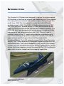
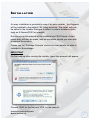
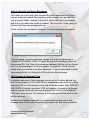
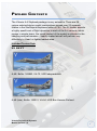
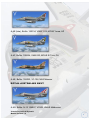
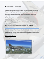
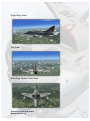
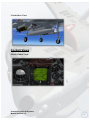
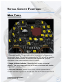
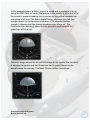
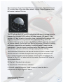
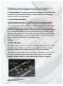
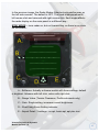
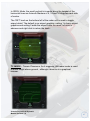
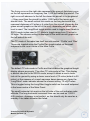
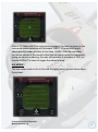
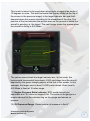
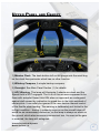
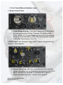
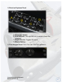
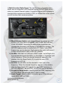
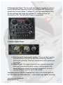
A-4 Skyhawk
USER Manual
Virtavia Pty Ltd A-4 Skyhawk
Manual Version 1.0
0
Introduction
The Douglas A-4 Skyhawk was designed to replace the piston-engined
AD Skyraider in the close air support and interdiction role. It was capable
of carrying both conventional and nuclear weapons.The prototype flew
on 22 June, 1954.The first production model, the A-4A (165 built),
entered service in 1956. The A-4B (542 built) entered service in 1957.
The A-4C (638 built), entered service in 1960, and introduced a new
radar unit which provided limited night and bad weather capability. The
A-4E (498 built), was equipped with a more powerful engine and other
improvements and entered service in late 1962. The A-4F was a
modified version of the "E" model and included an upgraded engine,
nose wheel steering, wing spoilers, a zero-zero ejection seat, and an
upper avionics pod which gave the aircraft its characteristic
"humpback"shape. The A-4G entered service with the Royal Australian
Navy in 1967. It was armed with Sidewinder missiles and flew from the
carrier Melbourne. The Virtavia Skyhawk is a fully 'native' FSX release,
including the now standard technologies such as self shadowing, bloom
effects, and bump mapping, as well as support for the FSX Acceleration
addon with its carrier catapult and wire trapping capabilities.
Virtavia Pty Ltd A-4 Skyhawk
Manual Version 1.0
1
Installation
An easy installation is provided by way of an auto-installer , the Skyhawk
will be installed to the default FSX folder structure. The install path can
be edited in the Installer Dialogue to reflect a custom installation path
such as E:Games\FSX\ for example.
Extras such as this manual will be installed into FSX/Virtavia. A start
menu entry will also be made, with an uninstaller should you ever wish
to remove the product.
Please see the ‘Package Contents’ section for more details on what is
included in this package.
IMPORTANT
On first load-up after running the installer, these two prompts will appear:
Choose ‘RUN’ for the first and ‘YES’ for the second.
Virtavia Pty Ltd A-4 Skyhawk
Manual Version 1.0
2
Switch Sounds and Error Messages
FSX does not come with click sounds for switch operation and these
cannot simply be added like engine or wind sounds can, as .wav files
into a special folder. Instead, a new DLL library file has to be created
and this is run when the model is loaded. This new DLL is the cause of
the two first-time use prompts above.
Under certain circumstances however, an error message will appear :
This will apear if another Slyhawk variant in the Virtavia package is
loaded IN EXTERNAL VIEW. It has to do with the licencing system of
the sounds DLL file. When this message appears, the sim will be frozen
until it is acknowledged. It will not appear if you are in Virtual Cockpit
mode when you switch to another Skyhawk. It can be cancelled it easily
by pressing Enter, or clicking the OK button on the message.
FSX Freezes in External View
A problem can arise if the message comes up but is either behind the
main view window of FSX (with FSX in windowed mode) or is not visible
because FSX is in full-screen mode (the Alt-Enter mode). After TWENTY
SECONDS of normal operation, FSX will appear to freeze up (although
engine sounds continue) and pressing keys will result in the standard
FSX error ‘ping’ sound. The answer is to simply press Enter and control
will be restored.
Switching to another Skyhawk in VC mode will not give rise to this
message due to the way the panel.cfg is read in by the licence checker.
Virtavia Pty Ltd A-4 Skyhawk
Manual Version 1.0
3
Credits
Exterior model - Mesh Factory, Phil Perrott
External Textures - Phil Perrott, Frank Safranek
Interior model - 3D Reach, Phil Perrott
Gauge and animation coding – Phil Perrott
Radar - Karol Chlebowski
Flight Dynamics - Mitch London
Engine Sounds - Phil Perrott
Switch Sounds - Dan Dunn
Manual - Phil Perrott
Testing - Frank Safranek, Mitch London, Phil Perrott
Additional beta testing by :
Lt J.L. “Mouth” Pennington, A-4F pilot, late 1970’s.
Wing Commander Barry Magann, 1. Sqn., RAAF (current F/A-18F pilot).
Virtavia Pty Ltd A-4 Skyhawk
Manual Version 1.0
4
Support
Should you experience difficulties or require extra information about the
Virtavia Skyhawk, please e-mail our technical support on
[email protected]
Copyright Information
Please help us provide you with more top quality flight simulator models
like this one by NOT using pirate copies. The flight simulation industry is
not very profitable and we need all the help we can get. Please - help us
grow by buying a legitimate copy.
These files may not be copied (other than for backup purposes),
transmitted or passed to third parties or altered in any way without the
prior permission of the publisher.
The source code for this product is closed. No modifications or reverse
engineering may be carried out without prior consent from Virtavia Pty
Ltd.
All rights reserved – copyright Virtavia Pty Ltd 2012
Virtavia Pty Ltd A-4 Skyhawk
Manual Version 1.0
5
Package Contents
The Virtavia A-4 Skyhawk package is very extensive. There are 26
unique exterior/interior model combinations spread over 22 separate
folders in the SimObjects\Airplanes folder of FSX. The 22 folders provide
a highly specific set of flight dynamics to each of the A-4 variants, which
means in simple terms, the visual loadout of the model is reflected in the
handling and performance – heavily-loaded aircraft will perform very
differently to ‘clean’ or lighter-loaded ones.
Included Texture Sets
US navy
A-4E, BuNo. 149993, VA-72, USS Independence
A-4E (late), BuNo. 152031, VA-94, USS Bon Homme Richard
Virtavia Pty Ltd A-4 Skyhawk
Manual Version 1.0
6
A-4F, BuNo. 155022, VA-164, USS Hancock
A-4E, BuNo. 151118, VA-43, NAS Miramar
A-4F ‘Super F’, BuNo. 154179, NAS Pensacola
Us marines
A-4E, BuNo. 150095, VMA-331, USS Forrestal
Virtavia Pty Ltd A-4 Skyhawk
Manual Version 1.0
7
A-4E (late), BuNo. 150134, VMAT-102, MCAS Yuma, AZ
A-4F, BuNo. 155064, VMA-223, MCAS El Toro, CA
A-4E, BuNo. 150023, VF-126, NAS Miramar
Royal Australian navy
A-4G, BuNo. N-13 154907, VF805, HMAS Melbourne
Virtavia Pty Ltd A-4 Skyhawk
Manual Version 1.0
8
A-4G, BuNo. N-13 154906, VF805, HMAS Melbourne
Exterior Model
The exterior model has all the usual animations such as canopy,
speedbrakes, ailerons, elevators etc as well as some custom ones :
Wing spoilers (automatic)
Armed by a switch in the cockpit, these will deploy on touchdown and
retract as soon as throttle is re-applied. A red warning light will illuminate
on in the panel when the spoilers are deployed. They will not work in
flight, where retardation is taken care of by the rear speedbrakes. The
wing spoilers are not available on the early ‘E’ variants.
Access ladder
Not an animation as such, the ladder will appear when the engine is off
and has spooled down to a halt AND the wingfold key has been pressed.
This is not assigned by default in FSX, so users may have to assign a
key. The F key is ideal for this task. Pressing the wingfold key a second
time will hide the ladder, but be patient as there is a short delay before
the ladder vanishes.
Pilot
The pilot figure can be toggled using ctrl-W.
Virtavia Pty Ltd A-4 Skyhawk
Manual Version 1.0
9
Exterior Lighting
Pressing the L key will turn on all lights, you may however wish to turn
them on using the appropriate switches in the cockpit, as the L key also
puts the on formation, refuel, underwing, taxi lights and both red and
white flood lighting in the cockpit, which should ideally be switched
separately.
Shift-L will toggle the nav lights and the cockpit lights.
Crtl-L will toggle the taxi light.
Please refer to the cockpit section of this manual for information
regarding light switch location.
Alternative Viewpoints in FSX
There are several different ways of looking at the the aircraft and the
cockpit, select these alternative views by right-clicking in an empty area
and picking the 'Aircraft' menu for external views and the 'Cockpit' menu
for views inside the cabin.
External View Options
Left Wing View
Virtavia Pty Ltd A-4 Skyhawk
Manual Version 1.0
10
Right Wing View
Tail View
Refuelling Tanker Crew View
Virtavia Pty Ltd A-4 Skyhawk
Manual Version 1.0
11
Undersides View
Cockpit Views
Attack Radar View
Virtavia Pty Ltd A-4 Skyhawk
Manual Version 1.0
12
Virtual Cockpit Functions
Main Panel
1) Gunsight switch. The gunsight reticle (‘crosshairs’) will appear on
the gunsight glass. The reticle is represented in FSX as best as possible
with some limited animation, it should not be regarded as a proper
simulation of the real movement of the A-4 reticle.
2) Angle of Attack Indicator. Shows the AoA in units, not actual
degrees. The correct approach AoA of 30 units is indicated with a white
bug at the 3 o’clock position.
3) Airspeed Indicator. Shows IAS in knots, with a separate Mach
number indicator segment on the left side. The knob at the bottom left is
Virtavia Pty Ltd A-4 Skyhawk
Manual Version 1.0
13
used to set the Autopilot Speed Hold value and is essential for speed
hold to work.
4) Artificial Horizon. The A-4’s AH is typical of the era in that it also
provides navigational control by using steering prompts in the form of
yellow bars for station direction (Localiser), glideslope indication and
Flight Director prompts as well as a separate glideslope bug, a bank
angle prompter and turn & slip indicators.
A) Aircraft Indicator. Represents the aircraft pitch and roll angle
with respect to the horizon ball.
B) Glideslope Indicator Bug. Used to indicate glideslope angle,
useful when Flight Director is in control of the yellow steering bars.
C) Bank Angle Pointer. Works in conjunction with the RMI indicator
settings. When the RMI NAV1 pointer is tracking a VOR or ILS signal
and the desired OBS course is set, the AH Bank Angle Pointer shows
which direction and by how much the aircraft should bank to reach the
correct heading to the tuned station. The maximum indication is 30
degrees of bank. The pointer consists of two triangular bugs, the top one
will indicate the direction in which to bank the aircraft, the lower one
indicates the amount of bank to apply. If the NAV1 signal is lost, the
pointer will zero itself in the vertical position.
Virtavia Pty Ltd A-4 Skyhawk
Manual Version 1.0
14
In the example below, a NAV1 station is tuned and a course to it is set
using the RMI OBS set knob. The course to the station is off to the left of
the aircraft’s present heading, this is shown by the yellow Localiser bar
prompting a left turn. The Bank Angle Pointer also says turn left (top
triangle) and is at its maximum indication of 30 degrees (bottom
triangle), showing that the desired heading is not close yet. The
Glideslope Bar (and bug) show that the aircraft is well beneath the
glideslope at this point.
The next image shows the aircraft on course to the station, the Localiser
is nearing the centre and the Glideslope bar is coming down as the
aircraft nears the runway. The Bank Pointer is also centralised.
Virtavia Pty Ltd A-4 Skyhawk
Manual Version 1.0
15
The last image shows the Flight Director in operation. The switch for the
FS is at the rear of the right-side console. A grey Flag will appear in the
left corner to show FD is on.
The FD will use the LOC and GS yellow bar indicators to prompt the pilot
towards the Autopilot HDG setting (left side console, AP panel). If the
vertical LOC bar is held in the centre, then the aircraft will maintain a 30
degree bank whilst turning towards the desired heading. Note, the
location of the bar in the centre of the ball does NOT mean the aircraft is
on course already, the bar will only stay in the centre if the pilot is turning
sufficiently towards the set heading, the object being to keep the bar
centralised. If the pilot levels the wings before the heading is reached,
the LOC bar will move off to the side, prompting further turning.
The horizontal GS bar does not have a function in the A-4 under Flight
Director as the A-4’s basic Autopilot does not permit an altitude to be
set, it merely holds the present altitude, but the same would apply for
that as for the LOC, ie. when held in the centre, the aircraft will steer to
the desired altitude.
D) Slip Ball. Standard slip indicator.
E) Turn Pointer. Standard turn indicator.
F) Aircraft Indicator Adjuster. Used to raise or lower the bar to
compensate for high angles of attack.
Virtavia Pty Ltd A-4 Skyhawk
Manual Version 1.0
16
5) Altimeter. Standard altimeter, knob left side for Baro Setting. Use
left/right mouse click, mousewheel or left click drag to adjust.
6) Accelerometer. The maximum and minimum g pulled during the flight
is shown by the twp smaller pointers, clicking the button on the gauge
bottom left will reset the pointers.
7) Vertical Speed Indicator.
8) Radio Magnetic Indicator. The RMI main disc is a simple compass
which indicates the present heading in degrees. The larger pointer is
NAV1, the smaller pointer is ADF. The numeric display shows the DME
reading from the current selected station, if available. The small white
triangle at the top of the display in the 12 o’clock position is fixed to show
the heading on the RMI disc. The knob bottom left is the OBS, or CRS
adjuster. The course set is shown both by the knob’s own tooltip and the
two-ended pointer at the gauge perimeter, which rotates as the knob is
turned, using left click drag or mousewheel input.
9) Clock.
10) APG-53A Radar.
The radar used in the A-4 is used for locating ground targets only, there
is no air-to-air capability, nor is there any target lock facility, it merely
provides a means of all-weather scanning of the ground ahead.
The Virtavia version follows the functionality of the real unit quite closely,
for user convenience it also adds airport data, which can be toggled
through 3 levels of detail. The red glare shield is lifted by clicking it.
Virtavia Pty Ltd A-4 Skyhawk
Manual Version 1.0
17
In the previous image, the Radar Modes Selector knob can be seen on
the left side console. The default is OFF. The knob is advanced weith
left mouse click and returned with right mouse click. Each mode affects
the radar display on the main panel in a different way :
STBY MODE – turns radar on, but not transmitting, so there is no return
on the screen :
A – Brilliance. Actually a dimmer switch with three settings, default
is brightest. Advance with left click, return with right click.
B – Range Value (Terrain Clearance, Profile sub-mode only)
C – Gain. Single setting, increases overall brightness.
D – Short/Long Zoom Setting indicator.
E – Airport Detail. 3 settings : no apt, basic apt, apt plus text.
Virtavia Pty Ltd A-4 Skyhawk
Manual Version 1.0
18
SRCH MODE – puts radar into SEARCH mode. The radar is now fully
operational and will return an image of the ground in front of the aircraft :
In SRCH Mode, the horizontal increment lines show either 8 miles or 4
miles distance from the aircraft, depending on the zoom level used. The
default zoom level is 40 miles, as shown in the indicator at the bottom of
the screen. This can be increased to 20 miles by clicking the Short/Long
toggle switch on the small subpanel in the lower centre of the Main
Panel :
Virtavia Pty Ltd A-4 Skyhawk
Manual Version 1.0
19
In SRCH Mode, the small vertical tick marks along the longest of the
horizontal lines are Azimuth Markers of 6, 18 and 30 degrees each side
of centre.
The ‘RET’ knob on the bottom left of the radar unit is used to toggle
airport detail. The default is no airport graphics, setting 1 is basic airport
graphics and setting 2 adds the airport code. As usual, left click to
advance and right click to return the knob :
TC MODE – Terrain Clearance. As it suggests, this radar mode is used
to show height above ground , although it does so in a graphical
manner.
Virtavia Pty Ltd A-4 Skyhawk
Manual Version 1.0
20
The fuzzy curve on the right side represents the ground, the sharp curve
on the left represents an imaginary line 1,000 feet below the aircraft. The
right curve will advance to the left the closer the aircraft is to the ground
– if they meet then the aircraft is within 1,000 feet of the terrain and
should climb. The small vertical tick marks on the long horizontal line
represent distances of 2 miles or 4 miles from the aircraft (shown by the
green aircraft graphic on the left of the unit), depending on which zoom
level is used. The Long/Short toggle switch used to toggle zoom levels in
SRCH mode is also used in TC Mode to toggle range from 10 miles to
20 miles. The chosen setting is displayed in the small aircraft graphic on
the left side of the unit.
The TC mode of the radar has itself two sub-modes, ‘Profile’ and ‘Plan’.
These are toggled using the Profile/Plan toggle switch on the small
subpanel in the lower centre of the Main Panel :
The default TC sub-mode is Profile and that enables the graphical height
display shown previously. The other TC sub-mode is Plan. This display
is almost identical to the SRCH mode, except it allows a much closer
look at the ground by using a closer zoom level of 10 miles (default is 20
miles), at the expense of a much narrower beam sweep arc. Again the
‘Long/Short’ zoom indicator shows the chosen setting, 10 or 20 miles.
This is toggled using the Long/Short toggle switch on the small subpanel
in the lower centre of the Main Panel.
The small horizontal tick mark on the left side of the unit indicates radar
altitiude. The long horizontal increment lines can be used as 1,000 ft
AGL markers. Accuracy is not perfect, so this should only be used as a
standby if the radar altimeter has failed.
Virtavia Pty Ltd A-4 Skyhawk
Manual Version 1.0
21
Also in TC Mode with Plan sub-mode engaged, the warning lamp on the
instrument panel coaming will illuminate ‘OBST’ if the aircraft height
above ground (radar altitude) is less than 1,000ft. With the real radar,
the terrain ahead of the aircraft within the set range would be measured,
giving an advance warning, the was not possible to simulate in FSX, so
normal RADALT is used to trigger the warning lamp.
A/G MODE The last radar mode is Air-to-Ground Ranging mode, shown below when
flying level :
Virtavia Pty Ltd A-4 Skyhawk
Manual Version 1.0
22
This mode is meant to be used when diving onto a target at an angle of
10 degrees or more. The bold horizontal line (barely visible at the top of
the screen in the previous image) is the target indicator bar and it will
descend down the screen according to the steepness of the dive. The
position of the bar indicates the precise area on the ground at which the
aircraft is pointing, ie. the target. The next image shows the screen when
the aircraft is diving in A/G Mode :
The yellow arrow shows the target indicator bar, In this mode, the
horizonontal incremental lines depict 4,000 yard steps from the aircraft,
depicted by the green triangle graphic at the foot of the screen. In this
example, the target area is about 10,000 yards ahead. Zoom level in
A/G Mode is fixed at 10 miles range.
11) Engine Pressure Ratio Indicator. EPR would normally be
adjustable but FSX does not support this. The knob on the gauge is a
simple adjuster for the indicator bug on the gauge and serves no
purpose.
12) Oil Pressure Gauge. Shows engine oil pressure in lbs/in2.
Virtavia Pty Ltd A-4 Skyhawk
Manual Version 1.0
23
13) RPM Gauge.
14) Exhaust Gas Temperature Gauge.
15) Low Fuel Warning Lamp. On when less than 170 Gals.
16) Fuel Flow Gauge.
17) Fuel Quantity Gauge. Shows internal fuel. Press and hold the
button marked ‘Fus/Ext’ at the far right of the central sub-panel (21) will
cause the fuel quantity of any external tanks to be shown. The gauge
can be tested by pressing and holding the button, top left on the subpanel (21). The pointer will fall to zero to indicate a fully working gauge.
18) Oxygen Quanity Gauge. To simulate O2 depletion the gauge is
linked to the Fuel Gauge, so a low fuel state will also show a low O2
state. The gauge has a red warning lamp when O2 quantity gets too low.
The lamp can be tested by pressing and holding the button, top left on
the sub-panel (21). The lamp will illuminate and the pointer will fall to
zero to indicate a fully working gauge.
19) Standby Artificial Horizon. As with the main AH, the knob at the
bottom right of the gauge can be used to adjust the airfraft indicator bar
at the centre of the horizon ball to compensate for high AoA states.
20) Radar Altimeter. The gauge has a SET knob which is used to move
the small triangular bug around the perimeter of the gauge. The position
of the bug indicates the set low altitude warning threshold, when the red
warning lamp on the gauge will illuminate. If the aircraft exceeds 5,000 ft
AGL or banks more than 45 degrees, the device loses radio contact with
the terrain causing the OFF flag to show and the gauge pointer will
return its ‘home’ position, behind a small shield part.
21) Switch Sub-Panel. There are 5 active switches on this panel. From
left to right – NAV-GPS toggle (marked ‘BDHI NAV CMPTR’), OXY and
Fuel Gauges test button, Radar Sub Mode Selector (Profile/Plan), Radar
Zoom Selector (Long/Short), and Internal/External Fuel Display Selector.
The ‘Shrike Volume’ knob is non-functional.
22) Cabin Pressure Altitude Gauge.
Virtavia Pty Ltd A-4 Skyhawk
Manual Version 1.0
24
Upper Panel and Canopy
1) Mission Clock. The knob bottom left on the gauge sets the small bug
on the clock face perimeter which has no other function.
2) Whiskey Compass. A simple backup compass.
3) Gunsight. See Main Panel Section (1) for details.
4) APC Warning. This lamp will illuminate if wheels are down and the
Speed Hold is NOT engaged. The A-4s of this era were supposed to be
flown with autopilot Speed Hold ON when on approach as a safeguard
against stall caused by inattention to speed due to the high workload of
carrier pilots. It can safely be ignored if the user desires manual control
of the throttle when landing. The warning is deliberately not limited to the
in-flight condition – having it suddenly come on as the aircraft takes off
would be an unnecessary distraction, so the lamp is always on when on
the ground, which also serves as a convenient test. As soon as the gear
is retracted, the lamp will extinguish.
Virtavia Pty Ltd A-4 Skyhawk
Manual Version 1.0
25
5) Angle of Attack (AoA) Indexer.
The AOA indexer is comprised of three lights. The light indications are a
green chevron ( v ) showing 'too high AOA' at the top, a yellow doughnut
( O ) showing proper AOA in the centre, and a red chevron ( ^ ) showing
'too low AOA' at the bottom.
A GREEN chevron indicates that the nose must be
lowered and the throttle manipulated to suit.
An AMBER doughnut indicates that AOA is optimum for
the approach.
A RED chevron indicates that the nose must be raised
and the throttle manipulated to suit.
At intermediate stages the AOA indexer may also display
two symbols at a time. For example, a doughnut and a
green chevron would indicate that the aircraft is nearing
optimum AOA, providing the nose is lowered further. A
doughnut and a red chevron would indicate the
opposite.
6) Warning Lamp – Wheels Up. If the aircraft is slowing to land and the
flaps are deployed without the undercarriage being already extended,
this lamp will flash red to prompt the pilot to lower the gear.
7) Warning Lamp – Terrain. If the radar unit is in Terrain Clearance
(TC) mode and the sub-mode switch is set to ‘PLAN’, this lamp will
illuminate if the aircraft is less than 1,000 ft away from the terrain.
8) Warning Lamp – Fire. Illuminates when an engine fire is detected.
The A-4 has no extinguishing system so this would normally be an
indication to leave the aircraft, especially if accompanied by other faults
such as loss of power.
NOTE – the two central lamps are used for the LABS bombing system
and are not supported by FSX.
Virtavia Pty Ltd A-4 Skyhawk
Manual Version 1.0
26
Left Console
1) Landing Gear Lever. The yellow T-Bar handle below the landing
gear lever is for one-time emergency gear extension only.
2) Sim Icons. Quick links to FSX functions for ATC, Radios, GPS, Map,
Checklist and a Control Stick Hider icon.
3) Landing Gear Indicators and Flaps Gauge. A white ring is
displayed when the gear is up and locked. The red banded symbol
appears when the gear is in transition, or has stuck in an unsafe
position.
Virtavia Pty Ltd A-4 Skyhawk
Manual Version 1.0
27
4) Switch Sub-Panel.
A) Automatic Power Compensator (Speed Hold). Toggles
Speed Hold (SPD) on/off. NOTE – the Speed Hold must first be set to
the desired value using the knob on the Airspeed Indicator, otherwise
the throttle will move to idle and speed will drop off, resulting in a stall.
B) Spoilers Armed Warning Lamp.
C) Spoilers Arming Switch. When activated, the red lamp above
will stay illuminated. The spoilers will deploy automatically upon
touchdown, providing loss of lift (their primary function) and some
retardation. Note, retardation is mainly effected by the fuselage
speedbrakes and the toe brakes. In FSX, the spoilers use the reverse
thrust feature to apply some retardation and do not cause loss of lift.
When deployed, a red lamp will illuminate on the annunciator block on
the extreme left side of the main panel. The spoilers are cancelled as
soon as throttle is applied, the annunciator lamp will also extinguish. The
Spoilers Armed lamp will remain lit until the switch is returned to the OFF
position.
D) Stores Jettison Switch. This switch is used to hide the
weapons from view, simulating a ‘post mission’ state.
E) Flaps Switch.
Virtavia Pty Ltd A-4 Skyhawk
Manual Version 1.0
28
5) Throttle Panel.
A) Throttle Lever and Fuel Shutoff. The throttle is used in the
usual way to apply or reduce power. However it also doubles as the Fuel
Shutoff Valve and is so used to stop the engine.
ENGINE SHUTDOWN PROCEDURE :
Set throttle to IDLE. It is best to press the F1 key as throttle must be at
0% fo rthe shutdown to work, some controllers do not always go fully to
zero.
Virtavia Pty Ltd A-4 Skyhawk
Manual Version 1.0
29
Carefully position the mouse pointer over the small black button on the
end of the throttle lever. Look for the ‘Fuel Control Switch (open)’ tooltip.
Use a RIGHT MOUSE CLICK on the button and the throttle will do a
dog-leg movement back into the shut-down position and the engine will
spool down. Tooltip will now say ‘shut’.
RE-STARTING ENGINE :
RIGHT-CLICK on the small button again to re-opn the Fuel Valve and
also return the throttle to the normal idle position, ready for re-starting
(see next section).
Virtavia Pty Ltd A-4 Skyhawk
Manual Version 1.0
30
B) Pitch Trim Control Lever.
C) Rudder Trim Control Knob.
6) Engine Control Panel.
A) Starter Button. To use, first make sure the throttle is at idle, press
F1 if necessary. Then PRESS AND HOLD the starter button for
approximately 15 seconds until the engine is heard to start up.
B) Fuel Dump Switch. Provides dumping of fuel from the fuselage
tanks from the vent behind the starboard undercarriage nacelle. To
use, first click the safety ‘Fuel Control Manual’ Interlock Switch (D),
the lamp above will illuminate. Next, toggle the Fuel Dump switch
to ON. Fuel will rapidly deplete, leaving a faint trail from the vent
behind the aircraft when airborne. Return the Fuel Control Manual
Switch back to ‘Primary’ so the Fuel Dump switch cannot be
accidentally activated.
C) Flight Refuel Switch. This switch provides quick refuelling of the
aircraft, on the ground or in the air. The switch tooltip provides a
readout of the total fuel quantity in Pounds. It is also interlocked
with the Fuel Control Manual Switch (D), so that must first be
toggled on (lamp will come on). The switch is the ‘springloaded’
type, so the mouse must be held on, releasing too soon will stop
the refuelling process. The refuel rate is very fast, so the switch
need only be held for a few seconds. If the switch sticks in the ON
position, click again and it will return to OFF. Return the Fuel
Control Manual Switch back to ‘Primary’ so the Refuel Switch
cannot be accidentally activated.
D) Fuel Control Manual Switch. Provides a safety interlock for the
Fuel Dump and Refuelling switches.
Virtavia Pty Ltd A-4 Skyhawk
Manual Version 1.0
31
E) Fuel Control Manual Indicator Lamp.
7) Radar Control Panel.
A) Radar Modes Selector. The knob is advanced by left-clciking
and returned by right-clicking. There are four radar modes –
STBY, SRCH, TC (Terrain Clearance) and A/G (Air to Ground
Ranging). A full description of the radar and its modes is given
in the Main Panel section, Part (10).
8) AFCS Panel. The Automatic Flight Control System is essentially the
Autopilot of the Skyhawk.
A) Aileron Trim Knob. Although not strictly part of the autopilot
system, the aileron trim is nevertheless positioned on the AFCS
panel. Use left-click and drag, or mousewheel to adjust. A
tooltip will reveal the precise amount of trim applied.
Virtavia Pty Ltd A-4 Skyhawk
Manual Version 1.0
32
B) Autopilot Heading Display. Not the actual heading, but the
heading presently set for the autopilot HDG SEL function to
use.
C) Heading Set Knob. Typically found on a HSI, this knob will
adjust the value shown in the adjacent Autopilot Heading
Display window. Use left-click and drag or mousewheel to
adjust. Note – the HDG SEL switch must be on (in the up
position) for the dialled in heading to ‘take’. If the switch is off,
then the heading will revert to the present heading as soon as
either the HDG SEL switch or the AP Master switch is turned
on. Also, if the new heading is set, but the HDG SEL switch is
turned off and back on again, the heading will revert to the
present heading of the aircraft. This is useful if the desire is to
maintain the present course without having to make any further
adjustments using the heading SET knob.
D) Stab Aug Switch. This switch toggles the autopilot Yaw
Damper function.
E) Heading Select Switch. Toggles Heading Hold (see (C) above
for details.
F) Altitude Hold Switch. Toggles autopilot altitude hold. Note –
there is no way on the A-4 to set a desired altitude in advance,
the Altitude Hold switch will merely hold the current alititude, so
all climbng or ascending must be flown manually.
G) Autopilot Master Switch. This switch turns the whole AFCS
Unit on and off. NOTE – APC (Speed Hold) is a separate
system and is not affected by the Autopilot Master Switch. See
the Main Panel section of this manual for details about APC.
9) Canopy Lock Lever. Used in this model as a switch to open and
close the canopy.
Virtavia Pty Ltd A-4 Skyhawk
Manual Version 1.0
33
Right Console
1) Exterior Lights. Switches for all the exterior lights are on this panel.
A) Probe Light. This is the small red lamp embedded in the
leading edge of the right side engine intake. It is used only
when conducting air-to-air refuelling to illuminate the refuelling
probe.
B) Taxi Light. There are no landing lights on the A-4 Skyhawk.
Virtavia Pty Ltd A-4 Skyhawk
Manual Version 1.0
34
C) Anti-Collision Lights. These are the flashing red beacon
lights.
D) Fuselage Lights. The official description is ‘fuselage lights’
when in fact these lights are on the underside of the wings,
towards the wingtips. Their purpose is to illuminate the ground
underneath the aircraft when hooking up to the catapult bridle
at night.
E) Recognition Lights. These are plain white lights on the
wingtips, used when formating in low-visibility conditions, or
possibly for signalling.
F) Navigation Lights. These are the normal red/green/white
lamps found on all modern aircraft.
Important note on LIGHTS. Pressing the L key to turn on the lights will
turn ALL lights on at the same time, so the cockpit may appear unusually
red becaue the Probe Light will have been switched on. Also, the
Recognition and Underwing lights will be on, making the external
appearance rather unusual. It is far better to use the correct switches for
the required lights than pressing the L key.
2) Air Conditioning Panel.
A) Anti-Ice Switch. Toggles both the engine anti-ice bleed air
system and pitot heating.
Virtavia Pty Ltd A-4 Skyhawk
Manual Version 1.0
35
3) Electrical Systems Panel.
A) Generator Switch.
B) Seat Adjuster. Use right/left click to raise or lower the
viewpoint.
C) Flight Director. Toggles FD on/off.
D) Master Battery.
4) Trim Gauges Panel. Pitch Trim and Yaw Trim Indicators.
Virtavia Pty Ltd A-4 Skyhawk
Manual Version 1.0
36
5) Navigation Panel. The C-4418 Control Indicator Panel in the real
Skyhawk is slaved to the AN/APN-153(V) Doppler Radar Navigation Set,
which is a miniaturised radar navigation set used to continuously
measure ground speed and drift angle. This is simulated in FSX with a
combined Drift Angle / Ground Speed Indicator and a custom selector
switch / lamp setup.
A) Mode Selector Switch. For the unit to function, the selector switch
must first be set to LAND or SEA, depending on the nature of the
present flight. In LAND mode, the MEMORY lamp will illuminate if
the aircraft assumes a bank angle of more than 30 degrees and/or
a pitch angle of more than 25 degrees, signifying that the unit has
lost its return from the ground. In SEA mode, the same applies
except the values are reduced slightly to 25 and 20 degrees
respectively. Note that when passing through STBY, the red
MEMORY lamp will illuminate. This lamp signifies that the unit is
on but not yet transmitting. TEST mode will illuminate the
MEMORY lamp and set the Ground Speed readout in the adjacent
gauge to 121, signifying the gauge is functional.
B) Memory Warning Lamp. Indicates non-transmitting state of unit
or a loss of radar signal return due to excessive manouvering.
C) Combined Drift Angle / Ground Speed Indicator Gauge. The
pointer will only function in LAND or SEA modes. It indicates the
direction of the localiser of the tuned NAV1 station, similar to the
LOC needle on the Artificial Horizon. The Ground Speed Indicator
is a simple numeric readout.
Virtavia Pty Ltd A-4 Skyhawk
Manual Version 1.0
37
6) Navigation Control Indicator Panel. This panel is a representation
of the A-4’s basic FMC and displays various flight data readouts. FSX
cannot easily support a programmable anaolgue computer of this kind
with manual LAT/LON input, so the readouts, whilst accurate, are not
adjustable. The inputs would normally go to the RMI NAV1 needle under
a special ‘NAV-PAC’ mode to provide a steering prompt to the pilot. Note
the NAV-PAC selector switch (marked ‘BDHI NAV CMPTR’ on the main
panel, (21) in the diagram, Main Panel section) in the model works as a
NAV-GPS toggle, thereby providing similar functionality to the NAV1
needle as would have the analogue FMC. The ‘20’ would in the real
Skyhawk refer to the current selected MCL (‘Manual Carrier Landing’)
channel preset, roughly equivalent to the modern APR autopilot function.
Virtavia Pty Ltd A-4 Skyhawk
Manual Version 1.0
38
7) Multi-Function Radio Panel. The real A-4 has a Communication
Radio with an integrated ADF Receiver and a VORTAC Radio which
relies on a preset channel system. It would be impractical to attempt to
simulate these systems accurately in FSX, so instead the model utilises
a multi-function radio receiever system.
A) Mode Selector Switch. Left clicking moves the switch from OFF
to NAV1 ACTIVE, NAV1 STANDBY, ADF, COM1 ACTIVE and
COM1 STANDBY. According to which mode is selected, the
correspoding frequency will display in the frequency window. The
ACTIVE frequency text is marked with a ‘+’. Note – only STBY
frequencies can be adjusted. Right-clicking the switch will move it
in steps anticlockwise, back to the OFF position.
B) Set Mhz. With NAV or COM set to STBY mode, use left/right click
to increment/decrement the MHz, ie. the integer or ‘hundreds’ part
of the frequency. When the desired frequency appears in the
window, click the Swap Switch (D) to push the new STBY
frequency in ACTIVE.
C) Set KHz. As with MHz, but the decimal or ‘tens’ part of the
frequency. When the desired frequency appears in the window,
click the Swap Switch (D) to push the new STBY frequency in
ACTIVE. Note ADF has no STBY, its ACTIVE can be adjusted.
D) Frequency Swap Switch. Used to push the STBY frequency into
ACTIVE status. Use left/right click (1-click to swap).
E) Audio Toggle. Used to switch the audio signal of the selected
mode (NAV, ADF or COM).
Virtavia Pty Ltd A-4 Skyhawk
Manual Version 1.0
39
8) Transponder Panel. The four right side adjuster wheels are used to
set the transponder frequency in the civil-only Mode 3/A. The first two
wheels are not used (Mode 1, military IFF only, not supported by FSX).
All othr switches and lamps are releated IFF comms and are not
functional in FSX. Use left-click & drag or mousewheel.
9) Interior Lights Panel.
A) Red Cockpit & Instrument Lighting. These switches operate
simultaneously to provide the low-level red lighting used for
most night operations. Both the instruments and the panels are
illuminated.
B) White Flood. This toggle switch will turn a general white light
which will illuminate the whole cockpit. It can be used at the
same time as the normal red lighting to augment it, or on its
own for a brighter general light in the cockpit.
Important note on LIGHTS. Pressing the L key to turn on the lights will
turn ALL lights on at the same time, so the cockpit may appear unusually
Virtavia Pty Ltd A-4 Skyhawk
Manual Version 1.0
40
bright because both red and white lights will be on at the same time. It is
far better to use the correct switches for the required lights than pressing
the L key.
Catapult Launches
If FSX Acceleration is installed, the Virtavia Skyhawk can be launched
from suitablly-equipped aircraft carriers using the standard keyboard
commands.
Note – not all variants are equipped with the bridle system – The Blue
Angels and both Adversary models do not have it.
Procedure :
ALIGN WITH CATAPULT
PRESS CTRL-i - Bridle system will appear and aircraft will ‘lock-in’ to
catapult system. If nothing happens, check alignment of aircraft with
catapult and try again.
SET FLAPS & TRIM – one division of flaps and 3 deg. nose-up trim.
More heavily loaded aircraft will require more nose-up trim.
SET RPM TO 90% - this is important, setting to 100% will cause the
aircraft to pitch down as it is launched down the deck.
LAUNCH – press ctrl-Spacebar.
INCREASE RPM TO 100%
RAISE GEAR AND RETRACT FLAPS
Virtavia Pty Ltd A-4 Skyhawk
Manual Version 1.0
41
Virtavia-A-4 SKYHAWK REFERENCE INFORMATION
For standard procedures, see the Checklists tab.
Total aircraft weight empty 10,391 lbs
Maximum take-off weight 24,500 lbs
Maximum landing weight (field) 16,000 lbs
Maximum landing weight (arrested) 14,500 lbs
NOTE: To adjust load, on the Aircraft menu, click Fuel and Payloads.
Reference Speeds for TOW 15,968 lbs :
Take-Off Run, ASL, calm. 1,950 ft
Take-Off Run, ASL, 25kt wind. 1,270 ft
Rate of Climb, ASL. 8,750 ft/min
Service Ceiling. 42,700 ft
Range, clean. 1,130 nm
Range, 3 x 300 tanks. 1,856 nm
Combat Radius / Mission Time 530 nm / 2.5 hrs
V1 - Takeoff Decision Speed (dry runway; std temp) 75 KIAS
VR - Rotation Speed (dry runway; std temp) Sea Level 90 KIAS (16,000
lbs)
V2 - Takeoff Safety Speed (dry runway, std temp) Sea Level 110 KIAS
(16,000 lbs)
Virtavia Pty Ltd A-4 Skyhawk
Manual Version 1.0
42
VREF - Landing Approach Speed (full flaps; gear down) 110 KIAS
(16,000 lbs)
VMO - Maximum Operating Speed 584 KIAS ASL
VLO - Maximum Gear Operating Speed 200 KIAS
VLE - Maximum Landing Gear Extension Speed 250 KIAS
VFE - Maximum Flaps Extended Speed 250 KIAS
Landing touchdown speed
Best Glide Speed
80 KIAS
130 KIAS (gear and flaps up; engine inoperative)
Stall speed, clean, 16,000 lbs.
80 KIAS
Stall speed, gear down, full flaps, 16,000 lbs. 70 KIAS
NOTE: For explanations of speeds used on this tab, see "V-speeds" in
the Glossary section of Help.
Virtavia Pty Ltd A-4 Skyhawk
Manual Version 1.0
43