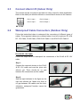
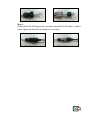
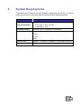
1
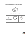
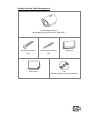
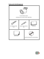
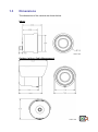
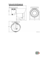
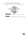
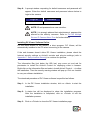
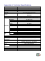
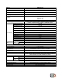
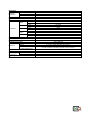
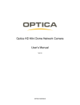
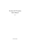
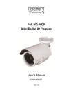
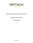
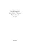
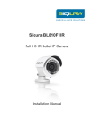
Mini Bullet IR IP Camera XIP-B01 PANTHER User’s Manual Ver. 1.2 Table of Contents 1. 2. Overview ................................................................................................................................ 2 1.1 Features ...................................................................................................................... 2 1.2 Package Contents ....................................................................................................... 3 1.3 Dimensions .................................................................................................................. 6 1.4 Connectors (Indoor Only)............................................................................................. 8 1.5 Function Cable (Outdoor Only) .................................................................................... 9 1.6 MicroSD Card Slot / Default Button ............................................................................ 10 Camera Cabling ................................................................................................................... 11 2.1 Connect Power .......................................................................................................... 11 2.2 Connect Ethernet Cable............................................................................................. 11 2.3 Connect Alarm I/O ..................................................................................................... 12 3. System Requirements ........................................................................................................ 15 4. Access Camera ................................................................................................................... 16 5. Setup Video Resolution ...................................................................................................... 19 6. Configuration Files Export / Import ................................................................................... 20 Appendix A: Technical Specifications ...................................................................................... 21 Appendix B: Delete the Existing DC Viewer .............................................................................. 25 Appendix C: Setup Internet Security ......................................................................................... 26 1 1. Overview The Full HD Multiple Stream Mini Bullet IR IP Camera XIP-B01 PANTHER, Camera is a compact camera with an easy setup design. PoE is supported to reduce complicated cabling without sacrificing performance. 3 Megapixel Resolution is available for providing high definition images. Quad Stream Compression (H.264 Baseline / Main / High Profile + MJPEG) are supported for efficient bandwidth and storage management. Moreover, the camera is featured with functions such as WDR, 3D Noise Reduction, Day/Night ICR, etc. For more camera features, please see the feature list below. 1.1 Features Progressive Scan CMOS Sensor 2M Resolution Quad Stream Support Dual Stream- Full HD 1080P Real Time + D1 Real Time Quad Stream Compression- H.264 Baseline / Main / High Profile + MJPEG Multi-language Support Wide Dynamic Range Two-Way Audio Support Motion Detection Privacy Masks Smart Picture Quality / 3D Noise Reduction Smart IR Mode Day/Night (ICR) IR LED Module (working distance up to 15m) microSD Support Weatherproof (IP66 International)* Sunshield Integrated Mounting Bracket with Cable Management* BNC Analog Output* ONVIF Support (*) Optional 2 1.2 Package Contents Please check the package contains the following items listed below. Indoor Full HD Multiple Stream Mini Bullet IR IP Camera XIP-B01 PANTHER Alarm I/O Terminal Block Quick Guide CD (bundled software and documentation) 3 Outdoor (without Cable Management) Full HD Multiple Stream Mini Bullet IR IP Camera XIP-B01 PANTHER Self Tapping Screws Plastic Screw Anchors (x5) (x5) Quick Guide Desiccant CD (bundled software and documentation) 4 Outdoor (with Cable Management) Full HD Multiple Stream Mini Bullet IR IP Camera XIP-B01 PANTHER Self Tapping Screws Plastic Screw Anchors (x5) (x5) Quick Guide Desiccant CD (bundled software and documentation) 5 1.3 Dimensions The dimensions of the camera are shown below. Indoor Outdoor (without Cable Management) 6 Outdoor (with Cable Management) 7 1.4 Connectors (Indoor Only) The diagram below shows the connectors of the IP Camera. Definition for each connector will be given as follows. Rear Panel 1 Rear Panel 2 Pin Definition No. 1 2 Connector PoE NETWORK Network LEDs 3 Alarm I/O 4 5 6 Power Jack LINE IN & LINE OUT VIDEO (BNC Connector) Definition For Ethernet cable and PSE connection Network connection and activity indication 1 Input − 3 Output − 2 Input + 4 Output + DC 12V connector for power connection Two-way audio transmission For analog videos output 8 1.5 Function Cables (Outdoor Only) RJ-45 Cable RJ-45 & DC 12V Cable Pin Definition No. 1 2 Connector RJ-45 Power Jack Definition For Ethernet cable and PSE connection DC 12V connector for power connection 9 1.6 MicroSD Card Slot / Default Button The positions of the microSD card slot and the default button are shown as below. MicroSD Card Slot Insert the SD Card in the microSD card slot to store videos and snapshots. Default Button Press the button with a proper tool for at least 20 seconds to restore the system. 10 2. Camera Cabling Before users connect cables, make sure that all cables and the power adaptor are placed in dry and well-waterproofed environments, e.g. waterproof boxes. The purpose is to prevent moisture accumulation inside the camera and moisture penetration into cables, which might lead to camera breakdown. Please follow the instructions below to complete IP Camera connection. 2.1 Connect Power For power connection, please refer to section Connectors (Indoor Only) for Indoor models, and see section Function Cables (Outdoor Only) for Outdoor models. Alternatively, users can power the camera by PoE. For Indoor models, use an Ethernet cable and connect it to the camera and a PoE switch. As for Outdoor models, connect the Ethernet cable to the function cable of the camera and a PoE switch. NOTE: If PoE is used, make sure Power Sourcing Equipment (PSE) is in used in the network. 2.2 Connect Ethernet Cable To have best transmission quality, cable length shall not exceed 100 meters. Connect one end of the Ethernet cable to the PoE Network connector of the camera for Indoor models or the RJ-45 connector of the function cable for Outdoor models. Then plug the other end of the cable to the network switch or PC. NOTE: In some cases, Ethernet Crossover cable might be needed when connecting the IP Camera directly to the PC. Check the status of the link indicator and activity indicator LEDs. If the LEDs are unlit, please check the LAN connection. Green Link Light indicates good network connection. Orange Activity Light flashes for network activity indication. 11 2.3 Connect Alarm I/O (Indoor Only) The camera equips one alarm input and one relay output for alarm application. Refer to the alarm pin definition below to connect alarm devices to the camera. 2.4 PIN 1: Input − PIN 3: Output − PIN 2: Input + PIN 4: Output + Waterproof Cable Connectors (Outdoor Only) Follow the instruction below to waterproof the connectors of different types of cables. The supported cables are as shown below, from left to right are: RJ-45 & DC 12V Cable, RJ-45 Cable, IP66 RJ-45 Cable 1 and IP66 RJ-45 Cable 2. RJ-45 & DC 12V Cable Follow the steps below to waterproof the connectors of the RJ-45 & DC 12V cable. Step 1: Connect the required devices to the RJ-45 & DC 12V cable and coat the joints with silicone gel. There should be no gap between the connectors and the cables. Step 2: Seal the spot indicated in the figure on the right with silicone gel. Make sure there is no gap between the cables and the hole; otherwise, waterproof function cannot be guaranteed. 12 RJ-45 Cable Follow the instruction below to waterproof the connector of the RJ-45 cable. Plug the Ethernet cable to the connector of the RJ-45 cable and coat the joint with silicone gel. Make sure there is no gap between the Ethernet cable and the connector; otherwise, waterproof function cannot be guaranteed. IP66 RJ-45 Cable 1 / IP66 RJ-45 Cable 2 For IP66 RJ-45 cable 1 and IP66 RJ-45 cable 2, please use an RJ-45 IP66 plug for connection to prevent water damage. Follow the steps below for cable connection. Step 1: Loosen the thread-lock sealing nut on the RJ-45 IP66 plug. For IP66 RJ-45 cable 2, please take out the supplied connector from the RJ-45 IP66 plug first. Then thread the Ethernet cable through the thread-lock sealing nut and the RJ-45 IP66 plug. If the Ethernet cable is attached to a connector already, please remove it first. IP66 RJ-45 Cable 1 IP66 RJ-45 Cable 2 Step 2: Carefully remove a section of rubber coating from the end of the Ethernet cable to reveal the wires. Inset the wires to the correct pins of the connector. Plug the Ethernet cable to the connector of IP66 RJ-45 cable 1 / cable 2. 13 IP66 RJ-45 Cable 1 IP66 RJ-45 Cable 2 Step 3: Fasten the RJ-45 IP66 plug to the connector of the IP66 RJ-45 cable 1 / cable 2. Lastly, tighten the thread-lock sealing nut to the plug. IP66 RJ-45 Cable 1 IP66 RJ-45 Cable 2 14 3. System Requirements To perform the IP Camera via web browser, please ensure the PC is in good network connection, and meet system requirements as described below. Items System Requirement 1. Intel® Pentium® M, 2.16 GHz or Personal Computer Intel® CoreTM2 Duo, 2.0 GHz 2. 2 GB RAM or more Operating System Windows VISTA / Windows XP / Windows 7 Web Browser Microsoft Internet Explorer 6.0 or later Firefox Chrome Safari Network Card 10Base-T (10 Mbps) or 100Base-TX (100 Mbps) operation Viewer ActiveX control plug-in for Microsoft IE 15 4. Access Camera For initial access to the camera, users can search the camera through the installer program: DeviceSearch.exe, which can be found in “Device Search” folder in the supplied CD. Accessing the Camera by Device Search Software Step 1: Double click on the program Device Search.exe. Step 2: After its window appears, click on the <Device Search> button on the top. All the finding IP devices will be listed in the page. Step 3: Find the camera in the list by its IP address and click on it. The default IP address of the camera is: 192.168.0.250. Step 4: The default IP address of the camera may not be in the same LAN as the IP address of the PC. If so, the IP address of the camera needs to be changed. Right click on the camera and click <Network Setup>. Meanwhile, record the MAC address of the camera, for future identification. Step 5: The <Network Setup> page will come out. Select <DHCP> and click <Apply> down the page. The camera will be assigned with a new IP address. Step 6: Click <OK> on the Note of setting change. Wait for one minute to re-search the camera. Step 7: Click on the <Device Search> button to re-search all the devices. Find the camera in the list by its MAC address. Then double click or right click and select <Browse> to access the camera directly via a web browser. 16 Step 8: A prompt window requesting for default username and password will appear. Enter the default username and password shown below to login to the camera. Login ID Password Admin 1234 NOTE: ID and password are case sensitive. NOTE: It is strongly advised that administrator’s password be altered for the security concerns. Refer to Full HD Multiple Stream IP Camera Menu Tree for further details. Installing DC Viewer Software Online For the initial access to the camera, a client program, DC Viewer, will be automatically installed to the PC when connecting to the camera. If the web browser doesn’t allow DC Viewer installation, please check the Internet security settings or ActiveX controls and plug-ins settings (refer to Appendix C: Setup Internet Security) to continue the process. The Information Bar (just below the URL bar) may come out and ask for permission to install the ActiveX Control for displaying video in browser. Right click on the Information Bar and select <Install ActiveX Control…> to allow the installation. Then the security warning window will pop up. Click on <Install> to carry on software installation. The download procedure of DC Viewer software is specified as follows. Step 1: In the DC Viewer installation window, click on <Next> to start the installation. Step 2: A status bar will be displayed to show the installation progress. After the installation is completed, click on <Finish> to exit the installation process. Step 3: Click on <Finish> to close the DC Viewer installation page. 17 Once the DC Viewer is successfully installed, the Home page of the IP Camera will be displayed as the figure below. NOTE: Please refer to Full HD Multiple Stream IP Camera Menu Tree for more button function details. 18 5. Setup Video Resolution Users can setup video resolution on Video Format page of the user-friendly browser-based configuration interface. Video Format can be found under this path: Streaming> Video Format. The default value of video resolution is as below. 2M H.264- 1920 x 1080 (30 fps) + H.264- 720 x 480 (30 fps) For more video resolution combination details, please refer to Full HD Multiple Stream IP Camera Menu Tree. 19 6. Configuration Files Export / Import To export / import configuration files, users can access the Maintenance page on the user-friendly browser-based configuration interface. The Maintenance setting can be found under this path: System> Maintenance. Users can export configuration files to a specified location and retrieve data by uploading an existing configuration file to the IP Camera. It is especially convenient to make multiple cameras having the same configuration. Export Users can save the system settings by exporting the configuration file (.bin) to a specified location for future use. Click on the <Export> button, and the pop up File Download window will come out. Click on <Save> and specify a desired location for saving the configuration file. Upload To upload an existing configuration file to the IP Camera, please first click on <Browse> to select the configuration file, and then click on the <Upload> button for uploading. 20 Appendix A: Technical Specifications Camera Image Sensor Effective Pixels Minimum Illumination White Balance Shutter Speed Lens Focal Length F Number 2M 1/2.7” Progressive CMOS 1920 (H) x 1080 (V) TBD Manual / AWB / ATW 1 ~ 1/10000 sec. 3.0 ~ 6.0 mm / 3.6 mm / 4.0 mm / 2.8 mm 3.0 ~ 6.0 mm- F 2.0 3.6 mm- F 1.8 4.0 mm- F 1.5 2.8 mm- F 2.0 Operation Multiple Languages Image Setting Audio Backlight Compensation White Balance Noise Reduction (3D) Wide Dynamic Range Privacy Mask Brightness Exposure Sharpness Contrast Saturation Hue Digital Zoom Motion Detection Privacy Mask Type ICR ICR + IR LED Tampering Alarm Indoor Two-way Audio Outdoor Compression Network Interface Video Compression Video Streaming Video Resolution Frame Rate Protocol Security Input Output Event Notification microSD Supported Web Browser User Account Password Levels Alarm English / French / German / Italian / Japanese / Korean / Portuguese / Russian / Simplified Chinese / Spanish / Traditional Chinese On / Off Auto / Manual / ATW On / Off On / Off On / Off Manual Auto / Manual Manual Manual Manual Manual Support On / Off / By Schedule Color Auto / On / Off / Smart Auto / LED On / LED Off / Smart IR / Light Sensor On / Off / By Schedule Terminal Block Pone Jack* G.711 / G.726 RJ-45, 10/100 Mbps H.264 / MJPEG Dual Stream- H.264 + MJPEG / H.264 + H.264 Quad Stream- H.264 x 4 / H.264 x 3 + MJPEG H.264- Full HD 1080P / SXGA / HD 720P / XGA / SVGA / D1 / VGA / CIF MJPEG- Full HD 1080P / SXGA / HD 720P / XGA / SVGA / D1 / VGA / CIF Single Stream- 1080P (30/25 fps) Dual Stream- 1080P (15/13 fps) + 720P (30/25 fps) IPv4/v6, TCP/IP, UDP, RTP, RTSP, HTTP, HTTPS, ICMP, FTP, SMTP, DHCP, PPPoE, UPnP, IGMP, SNMP, QoS, ONVIF HTTPS / IP Filter / IEEE 802.1X 1 Set, 5V 10kΩ pull up 1 Set, Photo Relay Output 300V DC/AC HTTP / FTP / SMTP microSDHC 32GB support Internet Explorer (6.0+) / Chrome / Firefox / Safari 20 User and Administrator 21 Mechanical Working Distance Wavelength Number of LEDs Power Connection Bracket LED Indicator Indoor Alarm Outdoor Indoor Power Outdoor Indoor Connectors Ethernet Outdoor Indoor Analog Video Outdoor Indoor Audio Outdoor General Operating Temperature Humidity Weatherproof Standard Indoor Outdoor Dimension Outdoor w/ Cable Management Weight Power Source System Power Consumption Built-in IR Illuminator Regulatory Built-in IR Illuminator* up to 15 m 850 nm 18 PoE / DC Jack* Cable Management* Power / Link / ACT 4 of 7 Pin Terminal Block (Female) N/A DC Jack DC Jack of All in One Cable* RJ-45 RJ-45 of All in One Cable* 1.0 Vp-p / 75Ω, BNC BNC of All in One Cable* 3 of 7 Pin Terminal Block Phone Jack of All in One Cable* -10°C ~ 50°C (14°F ~ 122°F) 10% ~ 90%, No Condensation IP66 (Optional) ∅ 71.50 x 79.85 mm (∅ 2.82 x 3.14 in.) ∅ 71.50 x 100.00 mm (∅ 2.82 x 3.94 in.) ∅ 71.50 x 125.10 x 86.95 mm (∅ 2.82 x 4.93 x 3.42 in.) 330 g PoE / DC 12V 2.5 W 1.3 W FCC / EMC / LVD / RoHS (*) Optional 22 Camera Image Sensor Effective Pixels Minimum Illumination White Balance Shutter Speed Lens Focal Length 2M Real Time 1/2.7” Progressive CMOS 1920 (H) x 1080 (V) TBD Manual / AWB / ATW 1 ~ 1/10000 sec. 3.0 ~ 6.0 mm / 3.6 mm / 4.0 mm / 2.8 mm 3.0 ~ 6.0 mm- F 2.0 3.6 mm- F 1.8 4.0 mm- F 1.5 2.8 mm- F 2.0 F Number Operation Multiple Languages Image Setting Audio Backlight Compensation White Balance Noise Reduction (3D) Wide Dynamic Range Privacy Mask Brightness Exposure Sharpness Contrast Saturation Hue Digital Zoom Motion Detection Privacy Mask Type ICR ICR + IR LED Tampering Alarm Indoor Two-way Audio Outdoor Compression Network Interface Video Compression Video Streaming Video Resolution Frame Rate Protocol Security Input Alarm Output Event Notification microSD Supported Web Browser User Account Password Levels Indoor Outdoor Indoor Outdoor English / French / German / Italian / Japanese / Korean / Portuguese / Russian / Simplified Chinese / Spanish / Traditional Chinese On / Off Auto / Manual / ATW On / Off On / Off On / Off Manual Auto / Manual Manual Manual Manual Manual Support On / Off / By Schedule Color Auto / On / Off / Smart Auto / LED On / LED Off / Smart IR / Light Sensor On / Off / By Schedule Terminal Block Pone Jack* G.711 / G.726 RJ-45, 10/100 Mbps H.264 / MJPEG Dual Stream- H.264 + MJPEG / H.264 + H.264 Quad Stream- H.264 x 4 / H.264 x 3 + MJPEG H.264- Full HD 1080P / SXGA / HD 720P / XGA / SVGA / D1 / VGA / CIF MJPEG- Full HD 1080P / SXGA / HD 720P / XGA / SVGA / D1 / VGA / CIF Dual Stream- 1080P (30/25 fps) + D1 (30/25 fps) IPv4/v6, TCP/IP, UDP, RTP, RTSP, HTTP, HTTPS, ICMP, FTP, SMTP, DHCP, PPPoE, UPnP, IGMP, SNMP, QoS, ONVIF HTTPS / IP Filter / IEEE 802.1X 1 Set, 5V 10kΩ pull up N/A 1 Set, Photo Relay Output 300V DC/AC N/A HTTP / FTP / SMTP microSDHC 32GB support Internet Explorer (6.0+) / Chrome / Firefox / Safari 20 User and Administrator 23 Mechanical Working Distance Wavelength Number of LEDs Power Connection Bracket LED Indicator Indoor Alarm Outdoor Indoor Power Outdoor Indoor Connectors Ethernet Outdoor Indoor Analog Video Outdoor Indoor Audio Outdoor General Operating Temperature Humidity Weatherproof Standard Indoor Outdoor Dimension Outdoor w/ Cable Management Weight Power Source System Power Consumption Built-in IR Illuminator Regulatory Built-in IR Illuminator* up to 15 m 850 nm 18 PoE / DC Jack* Cable Management* Power / Link / ACT 4 of 7 Pin Terminal Block (Female) N/A DC Jack DC Jack of All in One Cable* RJ-45 RJ-45 of All in One Cable* 1.0 Vp-p / 75Ω, BNC BNC of All in One Cable* 3 of 7 Pin Terminal Block Phone Jack of All in One Cable* -10°C ~ 50°C (14°F ~ 122°F) 10% ~ 90%, No Condensation IP66 (Optional) ∅ 71.50 x 79.85 mm (∅ 2.82 x 3.14 in.) ∅ 71.50 x 100.00 mm (∅ 2.82 x 3.94 in.) ∅ 71.50 x 125.10 x 86.95 mm (∅ 2.82 x 4.93 x 3.42 in.) 330 g PoE / DC 12V 2.5 W 1.3 W FCC / EMC / LVD / RoHS (*) Optional 24 Appendix B: Delete the Existing DC Viewer For users who have installed DC Viewer in the PC previously, please remove the existing DC Viewer before accessing the IP Camera. Deleting the DC Viewer Activate the <Control Panel>, and then double click on <Add or Remove Programs>. In the <Currently installed programs> list, select <DC Viewer> and click on <Remove> to uninstall the existing DC Viewer. Deleting Temporary Internet Files To improve browser performance, it is suggested to clean up all the files in the <Temporary Internet Files>. The procedure is as follows. Step 1: In the web browser, click on the <Tools> tab on the menu bar and select <Internet Options>. Step 2: Click on the <Delete> button under the <Browsing History> section. Step 3: In the appeared window, tick the box beside <Temporary Internet Files> and click on <Delete> to start deleting the files. 25 Appendix C: Setup Internet Security If ActiveX control installation is blocked, please either set Internet security level to default or change ActiveX controls and plug-ins settings. Internet Security Level: Default Step 1: Start the Internet Explorer (IE). Step 2: Click on the <Tools> tab on the menu bar and select <Internet Options>. Step 3: Click on the <Security> tab, and select <Internet> zone. Step 4: Down the page, click on the <Default Level> button and click on <OK> to confirm the setting. Close the browser window, and restart a new one later to access the camera. ActiveX Controls and Plug-ins Settings Step 1: Repeat Step 1 to Step 3 of the previous section above. Step 2: Down the page, click on the <Custom Level> button to change ActiveX controls and plug-ins settings. The Security Settings window will pop up. Step 3: Under <ActiveX controls and plug-ins>, set ALL items (as listed below) to <Enable> or <Prompt>. Please note that the items vary by IE version. ActiveX controls and plug-ins settings: 1. Binary and script behaviors. 2. Download signed ActiveX controls. 3. Download unsigned ActiveX controls. 4. Allow previously unused ActiveX controls to run without prompt. 5. Allow Scriptlets. 6. Automatic prompting for ActiveX controls. 7. Initialize and script ActiveX controls not marked as safe for scripting. 8. Run ActiveX controls and plug-ins. 9. Only allow approved domains to use ActiveX without prompt. 10. Script ActiveX controls marked safe for scripting*. 11. Display video and animation on a webpage that does not use external media player. Step 4: Click on <OK> to accept the settings. A prompt window will appear for confirming the setting changes, click <Yes(Y)> to close the Security Setting window. Step 5: Click on <OK> to close the Internet Options screen. Step 6: Close the browser window, and restart a new one later to access the camera. 26