1
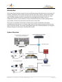
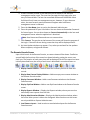
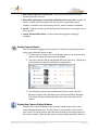
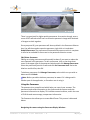
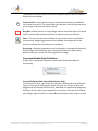
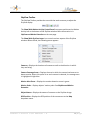
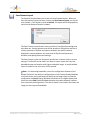
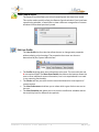
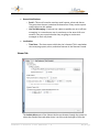
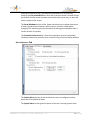
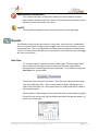
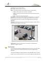
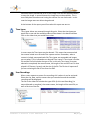
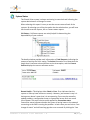
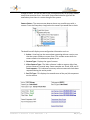
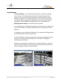
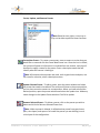
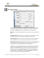
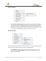
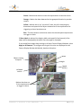
Remote Console User Manual Version 7.0 For Software Version 4.4 and above 2003, 2006, 2007, 2008, 2009, 2010 Pivotal-Vision™ 1325 American Blvd E, Suite #6 Minneapolis, Minnesota 55425 Phone 1.800.798.7499 • Fax 952.567.7490 Table of Contents Click on the page number to bring you to the page INTRODUCTION .......................................................................................................................................2 SYSTEM OVERVIEW ..................................................................................................................................2 QUICK START FOR USERS - LOGGING INTO THE SYSTEM ............................................................................3 THE REMOTE CONSOLE SCREEN ..............................................................................................................................4 Display Camera Selector ................................................................................................................................5 Display New Camera Display Window...........................................................................................................5 Using the Panorama ...............................................................................................................................8 Panorama Window Right Click Menu .....................................................................................................9 Display SkyView .......................................................................................................................................... 11 SkyView Toolbar ................................................................................................................................... 12 SkyView and Motion Detection ............................................................................................................ 13 Save Camera Layout ................................................................................................................................... 14 Load Camera Layout ................................................................................................................................... 15 Edit User Profile .......................................................................................................................................... 15 Viewer Tab ........................................................................................................................................... 17 Alert Preferences Tab ........................................................................................................................... 18 Alert Schedules Tab .............................................................................................................................. 19 Administration Configuration ..................................................................................................................... 20 Log-Off ........................................................................................................................................................ 20 REPORTS................................................................................................................................................ 20 DATE FILTER ..................................................................................................................................................... 20 STANDARD REPORTS .......................................................................................................................................... 21 Activity Report ............................................................................................................................................ 21 Site Overviews ............................................................................................................................................ 22 Time-Lapse ................................................................................................................................................. 23 User Recordings .......................................................................................................................................... 23 System Status ............................................................................................................................................. 24 User Status ................................................................................................................................................. 27 CAMERA WINDOWS ............................................................................................................................... 28 BASIC CAMERA NAVIGATION METHODS................................................................................................................ 28 PORTAL WINDOWS ........................................................................................................................................... 29 CAMERA DISPLAY WINDOWS .............................................................................................................................. 30 User Lock .................................................................................................................................................... 31 Image Streaming......................................................................................................................................... 31 Record Video .............................................................................................................................................. 32 Sync Cameras.............................................................................................................................................. 32 Presets ........................................................................................................................................................ 32 Adjust Camera Settings .............................................................................................................................. 34 Camera Display Window Right Click Menu ................................................................................................ 35 Camera Settings ................................................................................................................................... 35 I/O Outputs .......................................................................................................................................... 36 Points of Interest .................................................................................................................................. 37 Motion Indicators................................................................................................................................. 37 Administration ..................................................................................................................................... 39 Introduction The Pivotal Vision Remote Console is a site surveillance system that alerts users to any event of interest. It allows the user to either focus on the site of the alert event or, because the system is recording at all times, review the site from the recording and examine the event at a later date. The iAlert software can be connected to any existing security systems, such as temperature sensors, motion detectors, door or window interlocks, or other security devices. Any number of cameras can be used to monitor one or more sites. The system is completely automated, and many users can be connected to the system simultaneously. Any user can, in real time, take control of the system to examine the site of an alert or event of interest. This manual is designed to give users a brief introduction to using the different features of the Pivotal Vision Remote Console. System Overview Remote Console User Manual 7.0 2|Page The diagram above shows the main components of the iAlert System. Users at a Remote Console are shown in the box to the right; only one is shown but there may be many users at any given time. The Remote Console software permits users to access the system for viewing cameras, configuring the system, viewing alerts, and gaining access to reports. Note that there is no direct communication between users and the remote sites. All communication and viewing control of the devices on the left are via the System Management Server (SMS). The Intelligent Video Appliances (IVA’s) are at the remote sites that are being monitored. Having users communicate with the IVAs via the SMS speeds up communication and prevents conflicts when more than one user attempts to control a camera. Quick Start for Users - Logging into the System Users at an SMS gain access to the Remote Console installer via Internet Explorer. 1. Open Internet Explorer. 2. Enter the IP address or DNS name of your SMS and download/install the Remote Console. Your network administrator will let you know the exact address or method of access. 3. When the program is loaded, the Login Screen appears: Remote Console User Manual 7.0 3|Page 4. If there is already a name in this selection you can delete it and add your management server name. The next time you open this login page your new entry will be available. The last site connected will become the default. Most facilities will only have one management server; however, if more than one exists, the most recently used username will appear when a different management server is selected. 5. Enter the User Name given to you by the Network Administrator. 6. Enter the password for your User Name. You can choose to Remember Password for future logons. You can also choose to Connect Automatically to the last used management server when the application is launched. Note: User Names and Passwords are not case sensitive. 7. Click Connect. The gray bar at the bottom of the screen will show the progress of the Login. If there are errors during connection they will be displayed there. 8. An Auto-Update window may appear. If so, select yes and wait for the updates. When complete, re-login and connect. The Remote Console Screen Upon initial launch of the Remote Console, no camera views will be shown. Familiarize yourself with the functions of the menu bar shown below by putting the cursor over each icon. The function of each menu item will be displayed. Each of the menu bar items is briefly described here; the utility of each item is described in more detail later on. Display Camera Selector – Used to select the cameras you wish to view and control. Display New Camera Display Window – Adds an empty new camera window to the Remote Console screen. Display Panorama Window – Adds a new Panorama window to the Remote Console screen. Display SkyView Window – Adds a new SkyView window to the Remote Console screen. Display Reports Window – Displays the Reports window, where you can view and modify event reports from the IVAs. Display Administration Window – Displays the Administration window, where the entire iAlert system is able to be configured. Most functions on this screen are only available to System Administrators. Load Camera Layout – Used to select a saved window layout for the Remote Console screen. Remote Console User Manual 7.0 4|Page Save Camera Layout for Current User – Stores the current Remote Console window layout for later use. Edit profile, preferences, and activity notifications for current user – A place to enter or modify staff information such as user names, passwords, phone numbers, schedules, alert notification priorities, and site selection schedules. Log off – Logs the current user off the Remote Console prior to turning it over to the next User. Launch Thermal Video Player – Used to view thermographic imaging (if installed). Display Camera Selector Your first task after logging into the system is to select the cameras you wish to view on your Remote Console screen. 1. To select your first view, click on the Display Camera icon from the main tool bar to bring up the Show Cameras window. 2. The tree on the left side of the window will show your sites. Clicking on a site will show the cameras available for viewing there. 3. Click and drag a camera onto the Remote Console screen. The main Remote Console screen will display up to 24 Camera Display Windows. Each Camera Display Window provides the viewer full control of the camera. Display New Camera Display Window To add a blank camera window to the Remote Console screen, click on the Camera Display Window icon. This will launch a new window in the center of your screen. To view a camera, open the camera selector and drag a camera to the camera window. There are two types of camera display windows: Held and Remote Console User Manual 7.0 5|Page Portal. Knowing the difference is crucial to successful use of the Pivotal Vision software. The Camera Display Window will automatically appear as a Held window. Held refers to the window, not the camera. The camera will continue to track motion and view the site normally; however, a Held window will always show the same camera’s view. Unlike Held windows, Portal windows automatically change which camera’s view is shown. They show any activity that is happening at any site. When an alert is triggered, the Portal window will show the appropriate camera so that the activity can be monitored by the viewer. That Portal window will show the same camera until a new alert is triggered. If more than one Portal window is open, the new alert will be shown in the Portal window which has been viewing a single camera the longest without a new alert. To distinguish between Held and Portal windows look for the label in the upper right hand corner of each Camera Display Window. This icon not only identifies the kind of window, but also allows you to change window types. Clicking on the Held icon will change the window to a Portal window. The reverse also holds true. Click the Camera Display Window icon to add a window. The window can be moved by clicking and dragging the title bar, and resized by clicking and dragging a corner. Place several Held windows and several Portal windows on the Remote Console screen. Portal windows should usually be larger than Held windows because they display the important activities at a site. For the same reason, it is useful to set Portal windows to a higher frame rate and quality than Held windows. Setting Held windows to a lower level helps reduce bandwidth to the Remote Console. See Adjusting Camera Settings for more information. A drag and drop technique is used to change which camera any Camera Display Window is viewing. From the Camera Selector, left click and drag the camera’s image to the appropriate window. Alternatively, simply clicking on the camera image that is in the Camera Selector will place that camera into the Portal Window that has been static the longest. Remote Console User Manual 7.0 6|Page Display Panorama A panorama is what a camera can see in a 360° view. Panoramas are produced by the camera by taking small images and splicing them together. The Panorama is the preferred method of providing overall camera navigation and provides the ability for persons that are not familiar with the site to gain a perspective as to what they are looking at. Each camera can have several panoramas associated with it. This is because you may only want a panorama looking forward if the camera is against a wall, or you do not need to see the sky or the ground underneath the camera. New Panorama New panoramas are produced from the original Full View panorama. The Full View panorama is a 360° X 180° view that is all the camera can see. To create a new Panorama, have the Full View panorama in front of you in a window on the Remote Console. Click on the drop-down menu in the upper right of the Panorama window and click Manage Panoramas. Click New, enter a name, and then click Set Panorama Area. Simply drag a box across the area that you want your new panorama to be. You can adjust the blue box to customize the area. When you are satisfied with the area the blue box is covering, click Set. Remote Console User Manual 7.0 7|Page There is a zoom level for higher quality panoramas. Use caution though, even a zoom of 20% will take a half hour to create the panoramic image with hundreds of images to stitch together. Once you press OK, your panorama will show up blank in the Panorama Selector box. You will then need to open the panorama, right click on it and select Rebuild Panorama. The panorama will automatically open once this is complete. It will also be available for future use in the panorama selection screen. Edit/Delete Panorama Editing an existing panorama would normally be done if you want to reduce the area captured in the panorama. To edit a panorama, click on the drop-down menu in the upper right of the panorama window and click Manage Panoramas. Select the panorama you wish to edit and click Set Panorama Area. Resize the blue box and click Set, then OK. To delete a panorama, click Manage Panoramas, select which one you wish to delete and click Delete. Note: Before you edit or delete a panorama, be aware if it is being used in another part of the application, or if another user is using it. Using the Panorama The panorama is a powerful tool which helps you control your cameras. The panorama both sends information to the system and the system sends the panorama information to display. This includes camera locations, and in the case of FLIR infrared camera usage, temperature information. The Panorama also allows you to create Block Zones. This process is discussed below. Navigating the camera using the Panorama Display Window – Remote Console User Manual 7.0 8|Page The panorama provides many of the same navigation features that the Camera Display Window supplies. Point and Click – Simply click on the part of the panorama that you would like the camera to center to. The camera will then reposition itself, placing the center of the image at the point where you clicked. Drag Box – Allows the user to simply drag a red box around the region of interest and the camera will reposition and zoom to where the user has selected. Zoom – The user can use the scroll wheel on the mouse to zoom in and out of the panorama. Magnifying glasses are also available at the upper left of the panorama window for users without a scroll wheel. Drag Image – Because the panorama can be zoomed in, the image will obviously become larger than the display area. Pressing and holding the right mouse button allows you to move the visible region of the image. Panorama Window Right Click Menu A right click on a panorama launches a menu that will provide additional functionality. Create/Edit/Delete Block Zones (Administrator Only) To create a block zone, right click in the panorama window and select Edit Block Zones. If there are no existing block zones, this gives you the tool to draw the polygon that will become the block zone. Remember to complete the polygon by clicking on the first point you created with your last line. Once you have created your polygon right click with in it, select Block and choose either visual or motion Remote Console User Manual 7.0 9|Page detection. If Visual Blocking is turned on, a Filter option will appear in the right click menu. This allows you to select whether the image should appear black, white or pixilated when the area is viewed by the camera. If Motion Detection is selected, motion that originates within the blocked zone will not be detected. This is useful if a camera is by a highway, walking path, or trees, as these high movement areas will disrupt normal tracking. If motion begins outside of a blocked area and travels into the blocked area, the camera will continue tracking that motion. Select a block zone by clicking once on the area blocked; you can then edit the zone. You will see the vertices of the polygon that form the blocked area. You can click and adjust each vertex to change the shape. To add a vertex, right click within the blocked zone and choose Insert Point. This will insert a point nearest to where you initiated the right click. To delete a block zone, right click on the zone and select Delete Block Zone. Once you are done adjusting your block zones, click Save. Rebuild Panorama To rebuild an open panorama, right click within the panorama window and select rebuild. Doing so forces a manual regeneration of the panorama. This will instruct the camera to retake all of the images that make the panorama and splice them together. You can schedule panoramas to be reproduced on a regular basis. This is accomplished in the administrator's configuration module. See the Administrators Manual for further information on scheduling events. Remote Console User Manual 7.0 10 | P a g e Display SkyView The SkyView button allows you to add a SkyView diagram to the Remote Console screen. The SkyView is an overhead image of a particular site. Many elements on the diagram are quick linked to different preset camera views. If you move the cursor over any blue shaded area, a tool tip will pop up with text stating the name of the quick link. To display the corresponding quick link in the image window, click that area on the diagram. Any JPG images can be loaded as SkyView diagrams. Images such as an overhead view of a site or building can be useful. Each camera can have several SkyView diagrams associated with it. This is because you may want a SkyView diagram to represent only a portion of the camera coverage area. To use a SkyView diagram, click on the Display SkyView Window icon. This will open a SkyView window. Note: A camera window must be open for a site to appear in the SkyView window. The drop down menu labeled Map in the upper right hand corner of the SkyView window allows you to select a SkyView image. You may have one or more SkyView diagrams that you are able to display; locate the SkyView that you would like to view and click on it. Note: Only the SkyView images for the currently selected site will appear in the drop down menu. To change which site is selected, use the Display Camera Selector to select the appropriate site and camera. You can also change which site is selected by clicking on the title bar of a camera display window; the SkyView site will change to the site associated with that camera window. Remote Console User Manual 7.0 11 | P a g e SkyView Toolbar The SkyView Toolbar provides the user with the tools necessary to adjust the SkyView display. The Show/Hide Motion Activity Control Panel icon opens and closes the Motion Activity bar at the bottom of the SkyView window. More information is in SkyView and Motion Detection on the next page. The Show/Hide SkyView Layers icon controls various aspects of the SkyView window. When clicked, the following menu appears: Cameras – Displays the locations of cameras as well as the direction in which they are facing. Camera Coverage Areas – Displays the area in which the camera has been set to detect motion. When this option is on and a camera is selected, its coverage area is highlighted in light blue. Motion Alert Zones – Displays the motion detection zones in green. Motion Paths – Displays objects’ motion paths. See SkyView and Motion Detection. Object Names – Displays the names of cameras on the SkyView image. GPS Position – Displays the GPS position of the mouse next to the Map dropdown menu. Remote Console User Manual 7.0 12 | P a g e The Zoom in/Zoom out icons allow the zoom level of the SkyView image to be changed. Changing the zoom level may also be done by using the scroll wheel on the mouse. SkyView and Motion Detection When a camera detects motion, it maps the path taken by the object onto the SkyView image. This appears as a red line marking where the object moved during a given activity. When you move the slide bar located at the bottom of the SkyView, you are able to see the last 6 hours of motion and the patterns that develop over that time. Remote Console User Manual 7.0 13 | P a g e Save Camera Layout The Remote Console allows you to save and recall named layouts. When you have the camera layout you want, click on the Save Camera Layout icon on the main toolbar. If this layout is saved as Default, this layout will be displayed the next time the Remote Console is loaded. The Save Camera Layout feature saves a number of configuration settings that have been set. Some properties that will be saved are: the position and size of camera, panorama, SkyView and reports windows, the specific cameras displayed in camera windows, the zoom level of SkyView and panorama windows, and quality/frame rate settings. The Save Camera Layout can be used to quickly save a custom view or custom settings. This feature can be used if you want to save a layout with very low bandwidth usage and another with higher bandwidth usage. A sample default layout is shown on the front cover of this manual. Note: For decreasing bandwidth, one of the configuration features of the Remote Console is the ability to configure each of the Camera Display Windows to refresh slower and to decrease the quality of the image. Keep in mind the configuration on Portal Display Windows should be set to a higher quality and frame rate than Held Display Windows because they switch between cameras that are actively tracking motion. The rule of thumb is the smaller and slower the image, the less required bandwidth. Remote Console User Manual 7.0 14 | P a g e Load Camera Layout The Remote Console allows you to load named layouts that have been saved. This can be used to quickly refresh the Remote Console window if you have been repositioning windows, or would like to view a different arrangement of camera windows that has been previously saved. Edit User Profile The User Profile has four tabs that allow the user to change some properties without altering critical settings. The properties that a user can alter are determined by the System Administrator. The Profile tab brings basic user information to the user. The icons with the red R are required fields. The Show Extra Details check box at the bottom allows the user to enter additional contact information, but is not required and is not used in any reporting functionality. The Viewer tab lets you select an alert sound and determine some aspects of camera motion. The Alert Preferences tab allows you to select which types of alerts are sent to the user. The Alert Schedules tab allows you to set an alert notification schedule and set the sensitivity level for different time periods. Remote Console User Manual 7.0 15 | P a g e Profile Tab Login o Login Name – This item cannot be modified. o Password – The user can change the password within the established password rules. Personal o First Name – This is used to personalize reports and display information as a part of the data indicating who is using the camera. o Last Name – This is used to personalize reports and display information as a part of the data indicating who is using the camera. o Phone Number - This number is used for general contact information and it is also used to send voice messages. Remote Console User Manual 7.0 16 | P a g e General Notifications o Email – This email is used to send any email reports, alerts and alarms. The group that the user is attached to determines if they receive system status reports to this address. o Use Text Messaging – Each user has a place to quickly turn on or off text messaging. In a case where a user is not always on the same shift or on vacation, they can control whether they are going to receive text messages on their cell phone. Localization o Time Zone – The time zone at which the site is located. This is used when time-stamping reports, alerts, and other features in the Remote Console. Viewer Tab The Activity Alerts part of the Viewer tab lets you browse through the system to select the sound to be made when there is an alert, and the length of time the Remote Console User Manual 7.0 17 | P a g e sound will continue to play. The sound can be turned on or off simply by checking the Play a Sound File box. Note that if the alert sound is turned off and the Remote Console screen has been minimized to the system tray, an alert will cause a popup on the screen. The Portal Windows portion of the Viewer tab allows you to adjust the amount of time a portal camera window is able to stay on a camera’s view before changing. This area also gives you the option of clearing portal windows after a certain amount of inactivity. The Automatic Camera Lock is a timer that suspends a camera’s automated movements when you manually move a camera using a Camera Display Window. Alert Preferences Tab The Activity Alerts portion of this tab allows the user to configure how they would like to be notified of alerts. The System Alerts section gives the option of the user receiving system alerts. Remote Console User Manual 7.0 18 | P a g e Alert Schedules Tab Master (Your Sites) – Activity notifications are based on sites. If a user should only receive alerts from a specific one or two sites, those specific sites can be selected. All sites that you have access to will be shown in this list. Alert Schedule – This is an interactive form where the user can click and drag times at which they would like to be notified of alerts. To delete a block of time (highlighted in green), click on the block to select it, then right-click to delete. Time Span Details – The start and end times of the currently selected time block will be shown here. Use the up and down arrows to fine-tune the times. Save Button – Once you have made your changes, press Save. If you wish to void any changes simply click on the close window X in the upper left hand corner of the window. Remote Console User Manual 7.0 19 | P a g e Administration Configuration This is where the system configuration takes place. Only authorized system administrators should see this icon. Refer to the Remote Console Administration Manual for more information in this area. Log-Off The Log-Off Icon allows the user to log out and return to the login page. Reports The Remote Console can provide reports in many ways. A new activity is established if there is a period of time in between input triggers, such as a motion detector or visual motion detection. This is a configurable time under system settings but is defaulted to 15 min. This means that if the there are no activities for a 15 min stretch the next trigger will start a new activity. Date Filter For all report types it is possible to select a date range. This date range allows you to select just the range of reports that you or the client might want to review without transferring extraneous information. This is done by clicking the Date Filter icon, shown below. Clicking this icon will open a new menu. From the menu, select the date range that you would like to view. The currently selected range is displayed to the right of the Date Filter icon. Only reports from this time period will be visible in the standard reports. Selecting Date or Date Range from the menu will cause a new window to appear. Simply click the arrow to the right of the date and select the appropriate day, as shown on the next page. Remote Console User Manual 7.0 20 | P a g e Standard Reports The standard reports can be selected from the drop-down menu: Activity Report Activity reports provide a list identifying the details of each activity. The activity form provides detailed information of what prompted the activity and the detail of what followed as a result. The Group area shows all the sites that you are monitoring. When a site is selected, the individual activities and the time that they occurred during the selected time period will be displayed. Priority Bar Each activity has a bar to the right of it, labeled Priority. This will visually display the amount of activity that has occurred. The visual display takes into account the average of the past 100 activities. In other words, if the average alert has been 50 priority points that will be 50% of the bar. By clicking on the activity, the details will be expanded in the right box labeled Activity Detail. The ACK icon to the right of the priority bar allows a user to acknowledge an activity. Once selected, the icon becomes a green check mark. The time, date, and user who acknowledged the activity are displayed above the details area. Remote Console User Manual 7.0 21 | P a g e The details area on the right displays: Date / Time – When the alerts occurred. Type – This displays the type of event that occurred. It may be either: Video – Video capture was initiated or completed. Event – Some sort of event occurred, in most cases visual motion was detected. Alert – Some sort of error has occurred. Description – A description of what happened is displayed here. If motion was detected, this will say where, for how long, and provide a link to the video corresponding to the event. If an alert, this will give details as to what has happened. Thumbnail – When visual motion is first detected, a snapshot is taken. Click on the thumbnail to enlarge, as seen below. Total Priority – Shows the priority bar for the activity. This displays how important or urgent a report is. Site Overviews Site overviews are typically immediately presented to the user via email. These reports provide a way to look back historically at previously gathered site overviews. The report will display the images gathered in native 640x480 views. To save an image to your local drive, place your cursor over the image and simply right click Remote Console User Manual 7.0 22 | P a g e and select either preview and print or save image. You will then be asked where to store the image. In some instances the image may not be available. This is most likely due to another user having the camera in a user lock mode. In this case the images were not able to be gathered. At the bottom of the report you will see who this report was sent to. Time-Lapse Time-Lapse videos are accessed through this point. Select the time lapse you would like to see and the available videos will be shown in the details window. Click on the video that you would like to view. In some cases the Time-Lapse may be aborted. This means that someone had the camera locked over the end of the capture section. Remember, when a camera is locked, automated tasks like Time-Lapse are suspended and images are not taken. This is indicated as an aborted Time-Lapse. A Time-Lapse is a video file and the file link includes the type of file, in this case Time-Lapse, its status, aborted or completed, the camera name, the length of the actual file as if it were played in 15 frames / second, and the size of the file. The file size is important if you are retrieving the file off site from the SMS. User Recordings When a user requests a custom live recording, this is where it can be retrieved. Select the site, date, and the camera that you recorded on and the available recordings will be displayed. The link to the video file includes the type of file (in this case Recording), its status (aborted or complete), the camera name, the length of the actual file, as well as the size of the file. Remote Console User Manual 7.0 23 | P a g e System Status The Pivotal Vision system is always monitoring its own vitals and informing the system administrator of changes in status. When selecting this report it is easy to see the current status of each of the systems. By selecting one of the sites under the site selection box, you will have the chance to see the System, IVA or Camera status reports. IVA Status – IVA Status reports are mainly helpful in determining the dependability of your network. The details window provides such information as Total Requests, indicating the amount of activity the IVA is seeing. The Active information is to determine the length that it has been active without a service interruption, and the Current Version displays the current software version. Recent Health – This displays either Good or Error. Error indicates that the system or IVA may have had errors recently. However, just because it says it is having errors doesn’t mean that it is not operating. Errors may be caused by update problems, configuration issues, or operational errors such as a recent loss of power. The same criteria can be applied for Connection status. Connection status indicates whether the system is having issues or the network connecting to the SMS is causing the problem. In both cases you can look at “Last change of status” and tell how long ago the error occurred. By clicking the “Last Remote Console User Manual 7.0 24 | P a g e change of status” link you are able to see a complete history of all system health events that caused an error. Users with System Administrator rights will be emailed any time there is a status change of the system. Camera Status – The camera status detects almost any possible error with a camera. From the Group box, simply select the camera you would like to check. The detail box will display some configuration information such as: Active – How long has the camera been operating without a major error that the system could not recover from. This number resets when the camera needs to be rebooted or power is cut. Camera Type – Displays the type of camera. Video Capture Type – The iAlert software is able to capture video from various cameras in several ways. Some examples are: Picolo, USB, and IP Total requests – This indicates how many camera movements have been requested during the active period. Pan Tilt Type – This displays the manufacturer of the pan/tilt component on the camera. Remote Console User Manual 7.0 25 | P a g e Several items are monitored, and gathered into groups such as: Camera Status – Monitors the communication to and from the camera head. In the event that the camera does not respond correctly, an error is produced. It also monitors any error codes that the camera outputs. In the event of any errors the system will try to correct some of the most common problems. If the problem is not corrected over a given time period, the system will power down and reboot in an attempt to regain proper operation. Pan/Tilt Status – The Pan/Tilt provides communications checks, position checks, and operational tests on a regular basis. Any error that is detected will change the status. Video Status – The system tests each frame to insure the video frame is complete. If there is a frame that is not complete then the system will try to correct the error. If the problem is not corrected over time, the system will power down and reboot in an attempt to regain proper operation. Camera Temperature – Some cameras have temperature sensors built into the camera heads or the pan/tilt housings. These temperatures are monitored and action is taken if the temperatures are not able to be maintained. The current going through the motors in the pan/tilt are regulated to either add or reduce heat in the housing. The camera temperature determines whether a fan or heat is activated. In any situation you can click on the Last Change of Status link to see the history associated with any changes. Remote Console User Manual 7.0 26 | P a g e User Status You can view user access by either the camera or the user. This report will provide full information each time a user logs on and what activity is associated with that user login. Select a camera or user to see the details for that entity in the details viewer. The right side of the window will display users’ logon information. Within the details area, you will see: Date/Time – Indicates when the user has logged on or off. User – The user name that logged on or off. IP Address – This displays the IP address of the computer where the user was using the Remote Console. Client type – This will display either Viewer (refers to Remote Console), or WEB (refers to the Web page version of the Remote Console). Description – This will display the connecting and disconnecting from the client. To the right of the connection type, it will display if the connection failed and why. This will also display attempts that did not meet the criteria to gain access. This type of information will be viewed under system. In addition to the connection statuses, you can see the cameras that were accessed. Remote Console User Manual 7.0 27 | P a g e Camera Windows A camera window allows you to directly position the camera anywhere you would like. There are several ways to navigate the camera using the Camera Display Windows. Note: ALL Camera Windows have tool bars. If not visible, move the cursor over to the left edge of the window; the toolbar will pop out from the side. Basic Camera Navigation Methods Point and Click – Simply click on the part of the image that you would like the camera to center to. The camera will then reposition itself, placing the center of the image at the point where you clicked. Drag Box – Allows the user to simply drag a red box around a region of interest and the camera will reposition and zoom to where the user has selected. To use the drag box, put the cursor on an active camera window and click/drag across the area that you wish to view. When the mouse is released, the area inside the box will enlarge to fill the camera window. The Zoom Icon – This allows the user to either click on the icon to zoom out 10% each click, or right-click the icon to zoom to the percentage of zoom desired. In addition, the user can use the scroll button on the mouse to change the zoom level. Presets – Allows the user to select a predefined preset and have the camera position exactly on that location. Panorama Window – The Panorama image can also be used to position the camera. The user may use the “Point and Click” and the “Drag Box” methods to move the camera via the Panorama window. SkyView Window – Users are allowed to place Quick Link boxes over a graphical image such as an overhead map. To position the camera to a Quick Link location, simply click on a Quick Link and the camera will reposition to the selected view. Remote Console User Manual 7.0 28 | P a g e Portal Windows The Portal Window is a Camera Display Window that automatically changes which camera it is displaying. When movement has been detected on any camera at a site, that camera will be displayed in the Portal Window. Portal Windows should be set to a larger window size, as the cameras that appear in this type of window are going to be displaying motion. Setting the frame rate and quality of these windows to a higher level is also recommended; see Adjusting Camera Settings for a description of this process. A Portal Window can be identified by a yellow PORTAL indicator in the upper right corner of the window. To change a Held window to a Portal window, click the Held icon. It is possible to have multiple Portal Windows. The newest alarm will replace the Portal Window that contains the oldest alarm. If the Portal Window is locked, activities will not change the displayed camera in that portal. See Camera Display Windows for information on locking and unlocking camera windows. By default a camera feed is not displayed in a new Portal Window. To display a view in the Portal Window, click on the Camera Selector button located on the title bar and drag a camera to a Portal Window. Remote Console User Manual 7.0 29 | P a g e Camera Display Windows An alarm has been triggered by motion detection at the monitored site. The cause of the trigger is shown in the outlined box. Current Information Bar: The Current Information Bar displays the camera’s SITE\CAMERA NAME, as well as its orientation: Pan indicates the degrees from straight ahead (0°) to which the camera is pointing. This is used to provide left and right reference points. Tilt indicates the degrees from level (0°) to which the camera is pointing. This is used to provide up and down reference points. Zoom is the camera’s zoom level, displayed as a percentage. Remote Console User Manual 7.0 30 | P a g e User Lock Located in the pop-out menu in every Camera Display Window, this feature allows the user to take control of a camera. Clicking on the User Lock button will stop any other user or automated processes from controlling the camera. Automated processes may consist of pans, panoramas, time lapses, or guard tours. A Red information bar will show up on the bottom of the viewer indicating that you have control of the camera. All other users currently viewing that camera will see a blue information bar indicating the name of the user that currently has control of that camera. This lock is interruptible by another user if that user clicks on the lock button in their Camera Window. This is to ensure that anyone can regain control of a camera if needed. The other users will be notified with a blue bar that you have needed to regain locked control. Image Streaming This feature enables or disables the live streaming of video in the Camera Display Window. By default this feature is enabled. When disabled, the Camera Display Window will show a high resolution picture of where the camera was positioned when this option was disabled. The user may still move the camera when this option is disabled; the screen will refresh with a newer image once the camera has repositioned itself. Although the image in the Camera Display Window is frozen when this feature is disabled, the camera will continue to track and record motion. Zoom When a user clicks this icon, the camera will zoom out 10%. The user may also right click the icon and select the percentage of zoom desired. Additionally, the user may use the scroll button on the mouse to adjust zoom levels. Note: A fixed camera is unable to zoom. Remote Console User Manual 7.0 31 | P a g e Record Video To record a camera you are currently viewing, click the record icon. A red light in the center of this button and a •REC symbol in the lower right corner of the Camera Display Window indicates that you, another user, or an automated service is currently recording this camera. Clicking the button again will stop the recording process, or it will be automatically stopped after one hour of user recording. Once the recording is stopped or has timed out, the video will be available in the Reports window. See User Recordings for more information. Note: The recording may not be immediately available on the report page. This is dependent on the speed of the network in transferring the video from the IVA to the SMS. Sync Cameras (Multiple PTZ cameras only) This allows the user to move two or more cameras in tandem. This is normally used when there is a visual light and a FLIR infrared camera at the same site. To enable Sync Cameras, click the Sync icon in the Camera Display Windows you wish to sync. Cameras that are synced will view to projected ground planes, not to specific objects. Once two or more cameras are synced, navigating with one camera will cause the other will move to the same geospatial location. This will allow the user to navigate with the visual light camera while the FLIR infrared camera displays the temperature information. Presets Presets allow for fast and easy camera navigation. A preset is a set point or view that a camera will automatically return to when the preset is selected. These are useful for quick checks of important locations. Remote Console User Manual 7.0 32 | P a g e Create, Update, and Remove Presets Note: Based on user rights, a user may or may not be able to perform these functions. Create New Preset – To create a new preset, move a camera to a view that you would like to save and click the Create New Preset icon. Once the icon is clicked, the system will pause as information is retrieved from the camera, and you will be asked to supply a name for the preset. Enter a descriptive name that will identify what the camera is looking at. Note: All instances where presets are used, such as guard tours and pans, use the name for selection; select a descriptive name. Update Selected Preset – To edit a preset, open the preset window and select the preset that needs to be edited. The camera will move to the preset position, you can then move the camera to a new position. When you have selected the desired position, open the presets window and select the update icon. Make any name changes in the Update Preset window. Click OK to update. Remove Selected Preset – To delete a preset, click on the preset you wish to delete and click the Remove Selected Preset icon. Note: When a preset is deleted, it will delete that preset from guard tours, pans, time lapses, and reports. Be careful the preset you are deleting is not a critical part of the configuration. Remote Console User Manual 7.0 33 | P a g e Adjust Camera Settings The Camera settings form provides control of features on each camera. Click the Adjust Image Settings icon to adjust camera viewing settings. Move the controls by clicking on the slide bar and dragging it left or right to the desired setting. Click the Apply button to view the camera with the new settings. Brightness controls the overall brightness of the image. The scale ranges from 0 to 100. Still Image Quality adjusts the resolution or DPI (dots per inch) of the screenshots provided by the camera. The quality may be altered from 0% to 100%. Streaming Quality defines the resolution or DPI (dots per inch) of the streaming video provided by the camera. The quality may be altered from 0% to 100%. Streaming Frame rate indicates the number of frames-per-second currently being received by the Camera Display Window. In order to allow for the maximum streaming frame rate, the streaming quality should be lowered. The ability to control the bandwidth of each window independently allows great flexibility in limiting bandwidth on the intranet, over the internet, or in private networks. In the case of slower networks, the user may want to reduce the streaming frame rate to seconds per frame in smaller Camera Display Windows. Portal Window(s) should always be set to frames per second, as they switch between cameras that are displaying important motion. Remote Console User Manual 7.0 34 | P a g e The current camera status is shown on the bottom of the Image Settings window. This includes the actual streaming frame rate, the network data transfer rate, and the packet size. Note: The small black triangles found under the Streaming Quality and Streaming Frame rate slide bars in the Image Settings window indicate the user with the highest settings for that camera. If another user is viewing that camera with higher settings that you are, your Camera Display Window will automatically give you the higher quality that the other user is requesting from the camera. Camera Display Window Right Click Menu Camera Settings Each Camera Display Window has the ability to control the camera associated with it. Initialize allows the user to fully re-initialize the camera. This will reset all camera settings to default, place the camera in calibration mode and cycle the pan/tilt through a calibration mode as well. Cycle Power instructs the camera to power down, power up and re-load the default settings. Perform Auto Focus will force the camera to re-focus itself. Activate Wiper instructs the camera to use its wiper to remove water or debris from the lens. Not all cameras have a wiper installed. Auto Focus will allow the camera to use its auto focus feature. Remote Console User Manual 7.0 35 | P a g e Infinite Focus will place the camera in an infinite focus condition. While the camera is in this condition, it will not be able to focus on objects closer than thirty feet. This option is useful in low light conditions, when focus cannot automatically be gained or if closer objects interfere with viewing objects that are farther away. All users that are currently logged into the Remote Console will be forced with this setting when it is selected. Note: Remember to turn off the Infinite Focus option when finished. Force Night Vision places the camera into near infrared mode (night vision). Back Light increases the light to overexpose images that have dark shadows. I/O Outputs This is where you can control output devices associated with each camera. The menu displays the current configured output devices and the on or off status of the device. A description of the output devices will be shown when an output is selected. Remote Console User Manual 7.0 36 | P a g e Points of Interest Selecting Show Points of Interest displays presets in the camera display windows as you maneuver a camera. This allows you to better identify what you are looking at. The “Points of Interest” are displayed on the screen and act as shortcuts which can be clicked on to immediately view a preset. To activate your Points of Interest, right click in a Camera Display Window and select Show Points of Interest. Motion Indicators When motion is detected, a box will outline the movement in the Camera Display Windows. The color of the box indicates what type of motion is being detected. When All Motion is selected, these four colored boxes will be shown in Camera Display Windows. If Validated Motion is selected, only validated motion, or red boxes, will be displayed. Remote Console User Manual 7.0 37 | P a g e Green – Motion that does not meet the requirements to sound an alarm. Orange – Motion has been detected at that geospatial location by another camera. Yellow – Motion that is in a “pre-alarm” state; the IVA is analyzing the dimensions and speed of the object to determine if the requirements for triggering an alarm have been met. Red – This box contains motion that meets the size and speed requirements to trigger an alarm. If Show Labels is selected, the height, width, and speed (in feet/second) of the object will be displayed by the boxes. See next page for examples. If you would like to apply these settings to all open Camera Display Windows, select Apply to All Cameras. To configure which types of motion are displayed in each Camera Display Window individually, deselect this option. Object is being analyzed Width Height Speed (Ft/Sec) Validated motion Motion that does not fit the requirements to trigger an alarm Remote Console User Manual 7.0 38 | P a g e Administration Note: Only users with administrator rights can see this option. Show World Point – When multiple cameras are viewing the same area of ground and the mouse is placed over one of the Camera Display Windows, a red dot will appear in the corresponding location in the other Camera Display Windows. Show Measuring Tool – When the user click-and-drags a box across a camera window, a green box will appear that measures the width and height of the box drawn. This is mainly used while calibrating cameras, but can be used to measure objects in the camera window. Show Crosshairs – This will place crosshairs on the camera window. This feature is mainly used for calibrating the cameras. Management Server/Intelligent Video Appliance – Inside each of these menus are various administrative options, such as restart and updating the configuration. Remote Console User Manual 7.0 39 | P a g e


![[MANUAL] WebCCTV User Manual 4.4.0.0](http://vs1.manualzilla.com/store/data/005886634_1-9e25e0c8c7fa6f72c2b69bbb4cc67aa8-150x150.png)