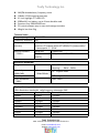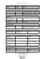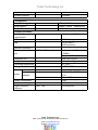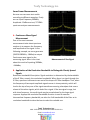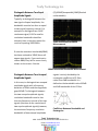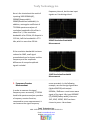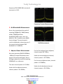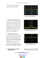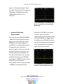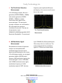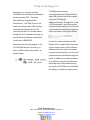
1
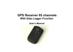
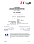
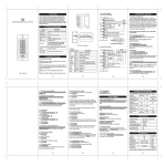
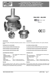
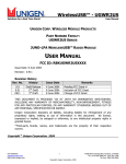
Tosfy Technology Inc. TC1204A Hand-held Spectrum Analyzer TC1204A handheld spectrum analyzer adapts high resolution of large 6.5 -inch screen with an impressive and delicate performance; The unit is small and light-weight which is easy to carry, with a 6000 mAH large-capacity rechargeable battery, it can continuously work up to 4 hours, and equipped with man-machine interface of a similar desktop spectrum analyzer, it possesses much advanced technical index which is superior to those from mainstream portable spectrum analyzer for applications of indoor and outdoor tests. It can also be connected to PC, by which it can display test images by controlling remotely. Universal USB and LAN communication interface make it more convenient to user-friendly measurement, with the standard complete SCPI command set, which can build and upgrade the integrated test system quickly. Features: Provided most handheld spectrum analyzer test function with superior technical index Frequency range: 9kHz~3.6GHz Optimum sensitivity: -148dBm Resolution bandwidth: 10Hz~3MHz Tosfy Technology Inc. Add.: 2159 SE 55th Ave.Hillsboro OR 97123 U.S.A Email: [email protected] Website: www.tosfy.com Tosfy Technology Inc. AM/FM demodulation, frequency count 100kHz~1.5GHz tracking generator 6.5 inch highlight TFT color LCD 6000mAH li-ion battery, up to 4 hours durable used. Structure Size: 288x182x142mm PC control software easy to save and manage test data. Weight: less than 3kg Technical index Frequency range Frequency resolution Frequency readout accuracy 9kHz~3.6GHz 1Hz ±(frequency marker count×frequency benchmark precision+1%×sweep width+10%×RBW+0.5×[sweep width/ (sweep point-1)]+1Hz) Aging rate <1ppm/year Temperature <0.5ppm (15℃~35℃) stability Internal standard (10MHz) Resolution bandwidth Range Selectivity (60dB/3dB) accuracy Video bandwidth (VBW) 10Hz~500kHz(from 1 to 10 serial stepping),1MHz,3MHz <5:1 typical value RBW≤500kHz <5% typical value 10Hz~3MHz Displayed average noise level (10Hz Resolution bandwidth, radio-frequency attenuator 0dB) frequency Pre-amplifier off Pre-amplifier pen 100kHz -90dBm -110dBm 1MHz -120dBm -140dBm 100MHz -125dBm -145dBm 500MHz -125dBm -145dBm 1000MHz -122dBm -140dBm 1.4GHz -120dBm -138dBm 1.8GHz -123dBm -140dBm 2.2GHz -121dBm -138dBm Tosfy Technology Inc. Add.: 2159 SE 55th Ave.Hillsboro OR 97123 U.S.A Email: [email protected] Website: www.tosfy.com Tosfy Technology Inc. 2.5GHz 3.0GHz 3.5GHz -121dBm -120dBm -120dBm -138dBm -137dBm -137dBm Phase noise Frequency offset 10kHz -80dBc/Hz Frequency offset 30kHz -90dBc/Hz Frequency offset 1MHz -115dBc/Hz Sweep time Sweep width 100Hz≤SPAN≤3.6GHz 0 sweep width Sweep mode 10ms~3000s 1ms~3000s Serial, single Frequency counter resolution Uncertainly angle 1Hz、10Hz、100Hz、1kHz Frequency count×frequency benchmark accuracy +counter resolution Range frequency(20℃~30℃) Synthetical range Input single range 0dBm~-50dBm frequency(90%) Range Maximum average continuous power permissible input Maximum input direct current voltage Input attenuator range 1dBpoint of compression Stray and residual response >30MHz TOI(CTB) SHI(cos) Input related stray ±1.5dB +27dBm 50Vdc 0~39dB,3dBstepping +7dBm +13dBm +30dBm <-60dBc Tosfy Technology Inc. Add.: 2159 SE 55th Ave.Hillsboro OR 97123 U.S.A Email: [email protected] Website: www.tosfy.com Tosfy Technology Inc. single residual response <-85dBm Tracing source Frequency range Output power Output flatness Common parameter Radio frequency input/output USB LAN 100kHz~1.5GHz -30dBm ~ 0dBm ±3dB SMA female(50Ω) USB 1.1(equipment side) 10/100 Base-T, RJ-45connector AM/FM modulation Benchmark input/out put 10MHz,BNC female Maximum size weight Operating temperature Storage temperature battery power input adapter output Power consumption Inside data storage Upper computer software 1dBstepping USB、LAN Input power 0dBm~ +10dBm output 0dBm±2dB 288×182×142mm Less than 3kg 0℃~40℃ -40℃~+70℃ 7.4V 6000mAh 100V~240V 50/60Hz 1.5A 9V 4000mA 13W 128MB Pc display test Tosfy Technology Inc. Add.: 2159 SE 55th Ave.Hillsboro OR 97123 U.S.A Email: [email protected] Website: www.tosfy.com Tosfy Technology Inc. Some Power Measurements Here we can see some test results according to different examples, Firstly we can input Frequency 300MHz, Amplitude -10dBm as a test, TC1204A spectrum analyzer measurements. A. Continuous Wave Signal Measurement One of the most common measurement tasks about spectrum analyzer is to measure the frequency and amplitude of the signal. In the following example, we use a generator (E4421B 300MHz, -10dBm) to output Continuous wave signal as the measuring signal. Here is the chart about the result of inputting 300MHz, -9.44dBm, Measurement of Sine Signal B. Application of the Resolution Bandwidth to Distinguish Closely Spaced Signals Resolution bandwidth Description: Signal resolution is determined by the bandwidth of the IF filter, namely, the resolution bandwidth. When there is a signal through the IF filter, spectrum instrument scans out of the shape of IF filter bandpass. Thus, when the frequency of two equal amplitude signals comes in close proximity, which will lead to the top of any one of the signal waveforms scanning a bandpass that covers almost all the other signals, which looks like a signal. If the two signals range, but with close frequency, the small signal may be overwhelmed by the large signal response. Appropriate resolution bandwidth function is used to measure Intermediate frequency bandwidth, we take the 3 db bandwidth of the filter as its resolution bandwidth to describe how to select the suitable one. Tosfy Technology Inc. Add.: 2159 SE 55th Ave.Hillsboro OR 97123 U.S.A Email: [email protected] Website: www.tosfy.com Tosfy Technology Inc. Distinguish Between Two Equal Amplitude Signals Typically, to distinguish between the two signals of equal amplitude, the bandwidth must be less than or equal to two signal frequency interval. For example, to distinguish two 1 KHZ continuous signal,1 KHZ or smaller resolution bandwidth should be selected. Here is the chart about the result of inputting 1800.5MHz (IF),50KHZ(Sweepwidth),1KHZ(Resoluti on bandwidth) 1KHZ Resolution Bandwidth Measurement If now the resolution band width(RBW) has been reduced to 100HZ,there will appear two signals, if you continue to reduce RBW, they will be more clearly shown on the screen. like this. 100HZ Resolution Bandwidth Measurement Distinguish Between Two Unequal Amplitude Signals In this case, to distinguish two unequal amplitude signals with a frequency deviation of 50kHz and the magnitude gap of 40dB. To distinguish between the two unequal amplitude signals, resolution bandwidth must be less than the frequency interval of the two signals (the same as the resolution of two equal amplitude signals),however, the maximum frequency resolution bandwidth of two unequal amplitude signals is mainly decided by the rectangular coefficient of IF filter, rather than 3dB bandwidth. It is defined as the bandwidth ratio of 60dB and 3dB bandwidth of the IF filter. Coefficient Between Bandwidth and Rectangular Tosfy Technology Inc. Add.: 2159 SE 55th Ave.Hillsboro OR 97123 U.S.A Email: [email protected] Website: www.tosfy.com Tosfy Technology Inc. Here is the chart about the result of inputting 1800.025MHz(IF), 500KHZ(Sweep width), 30KHZ(Resolution bandwidth). In addition, rectangular coefficient of TC1204A spectrum analyzer of resolution bandwidth of the filter is about 5 to 1, If the resolution bandwidth is for 30 kHz, 60 db point is 115 kHz, half the bandwidth is 57.5 kHz, which is more than 50 kHz frequency interval, but the two input signals can't be distinguished. 30KHZ Resolution Bandwidth Measurement If the resolution bandwidth has been reduced to 1KHZ, small signal overwhelmed can be shown .and the frequency and the amplitude difference of unequal amplitude signals included. 1KHZ Resolution Bandwidth Measurement C. Frequency Counter Measurement In order to measure the signal frequency more accurately, TC1204A hand-held spectrum analyzer provides a frequency counter function, compared to cursor measurement, it can measure the signal frequency more accurately. In the following example, we use the signal generator (Agilent E4421B) with output 500MHz,-10dBm as a continuous wave signal of the signal. We input 500MHZ (IF),10MHZ(Sweep width), there are 1HZ, 10HZ, 100HZ, 1KHZ can been chosen by users. Here shows Tosfy Technology Inc. Add.: 2159 SE 55th Ave.Hillsboro OR 97123 U.S.A Email: [email protected] Website: www.tosfy.com Tosfy Technology Inc. frequency 500.016666 MHz measured (accurate to 1 HZ). Frequency Counter Measurement D. N dB Bandwidth Measurement Here is the chart about the result of inputting 500MHz(IF), 1MHZ(Sweep width), 30KHZ(Resolution bandwidth).NdB is open, then the default is 3 N, if needed, press [NdB] key to change, The measurement result is displayed in the active area, If the current cursor dropped 3dB bandwidth is 31.666kHz; E. Adjacent Power Measurement We use a generator (E4421B 500MHz, -10dBm) to output Continuous wave signal as the measured signal. Here is the figure about the result of inputting 500MHz(IF) as a reference. N-dB Measurement For the first adjacent lanes adjacent, channel power-60.77dBm; Under the second adjacent channel, channel power is -63.70dBm; For the second adjacent lanes, channel power is -63.06dBm; The main channel power is 9.22 dBm Under the first adjacent channel, channel power is -61.83dBm; Under the third adjacent channel, channel power is -63.47dBm; Tosfy Technology Inc. Add.: 2159 SE 55th Ave.Hillsboro OR 97123 U.S.A Email: [email protected] Website: www.tosfy.com Tosfy Technology Inc. For third adjacent lanes adjacent, channel power is -64.62dBm. Adjacent Power Measurement F. Channel Power Measurement We use a generator (E4421B 500MHz, -10dBm) to output Continuous wave signal as the measured signal. Here is the chart about the result of inputting 500MHz(IF) as a reference .The measured results shows in the upper right corner of the display screen. Power channel is -9.81dBm. Channel Power Measurement G. Bandwidth Measurement We use a generator (E4421B 500MHz, -10dBm) to output Continuous wave signal as the measured signal. Here is the chart about the result of inputting 500MHz(IF) as a reference .The measurement results display in the split screen window of the second half window and the bandwidth is 35KHZ. H. Using Preamplifier for Small Signal Measuring Bandwidth Measurement We use a generator (E4421B 500MHz, -80dBm) to output Continuous wave Tosfy Technology Inc. Add.: 2159 SE 55th Ave.Hillsboro OR 97123 U.S.A Email: [email protected] Website: www.tosfy.com Tosfy Technology Inc. signal as the measured signal. Here is the chart about the result of inputting 500MHz(IF), 10MHZ(Sweep width), -20dBm(Reference level) as a reference. Using Preamplifier for Small Signal Measuring I. Harmonic Distortion Measurement We use a generator (E4421B 300MHz, -10dBm) to output Continuous wave signal as the measured signal. Input 200MHZ as its starting frequency, and1GHZ as its ending frequency, the fundamental, then the second harmonic signal and the three can be displayed clearly on the screen. you can also select Peak and Marker as a test. Press Peak button, then it marks fundamental frequency of 300MHZ, amplitude of -10DBM. On the second harmonic, you can read the measurement result : frequency offset is 300MHz, the magnitude of the difference is-26.55dB. On the third harmonic, you can read the measurement result. frequency offset is 601.333334GHz, the magnitude of the difference is-38.00dB.Then Here formed the testing output of graphics of the Fundamental and harmonic signal of spectrum analyzer. Harmonic Distortion Measurement Tosfy Technology Inc. Add.: 2159 SE 55th Ave.Hillsboro OR 97123 U.S.A Email: [email protected] Website: www.tosfy.com Tosfy Technology Inc. J. The Third Order Distortion Measurement In the following example, We use a generator (E4421B 500MHz, -10dBm) and another generator (E4422B 501MHz, -10dBm) to output Continuous wave signal as the measured signal. The two signals through a combiner are connected to RF input end of the spectrum instrument front panel. Then we set the parameter, input 500MHZ(IF),5MHZ(Sweepwidth),1KHZ( Resolution Bandwidth). The measured K. AM Modulation Signal Measurement Demodulation functions of spectrum analyzer can demodulate AM modulated signal from the carrier signal out and displayed on the screen. In the following example, we use signal generator (Agilent E4421B) which outputs a AM modulation signal as the measured signal: carrier is 100 MHZ, and 10 DBM continuous wave signal, modulation frequency of 1 KHZ, modulation depth of 100%. We also frequency and amplitude difference will display in the cursor area of screen. Here is the result. The Third Order Distortion Measurement input 100MHZ( IF),O(Sweepwidth),and 10ms sweep time as a reference. The measured period of the modulation signal is 1.233ms.here shows below. AM Modulation Measurement Tosfy Technology Inc. Add.: 2159 SE 55th Ave.Hillsboro OR 97123 U.S.A Email: [email protected] Website: www.tosfy.com Tosfy Technology Inc. Customers can control remotely TC1204A Hand-held Spectrum Analyzer by the standard SCPI(Standard Commands for Programmable Instruments)and USB. Connect the spectrum analyzer with USB interface automatically equipped to the PC correctly and turn on. Update wizard dialog box of PC hardware will pop up, please follow the wizard prompted to install driver USBDEVICE. Resources searched will appear in the "NI-VISA USB Devices" directory, as well as USB interface information, as shown below: TC1204A can be used to communication test. Double-click to open USB control side of the remote control of PC software. SARemoteControl. Through the "view > SCPI command", open the remote command control panel, you can send commands and read data through the panel. As shown in the figure below: As well as to be controlled via LAN. Double-click to open LAN control side of the remote control of PC software SARemoteControl, open the remote command control panel, you can send commands and read data through the panel. In addition, excellent guidance to troubleshooting and maintenance, fault diagnosis and troubleshooting and repair of TC1204A can be offered according to customers’requirement. Tosfy Technology Inc. Add.: 2159 SE 55th Ave.Hillsboro OR 97123 U.S.A Email: [email protected] Website: www.tosfy.com Tosfy Technology Inc. Ordering Information: Standard Configuration TC1204A Hand-held Spectrum Analyzer Spectrum analyzer Host 9kHz to 3.6GHz CD-ROM User's Manual Programming Manual AC / DC adapter AC input +9 V output power cord 220V/110V AC Options TC1204A -TG 100 KHZ to 1.5 GHz tracking signal source TC1204A -RBW 1 HZ resolution bandwidth TC1204A -AMA Audio demodulation, AM measurement, FM measurements, high-fidelity headphones PC Spectrum PC, PC software, LAN and USB connection cable TC1204A -BAG Portable Soft package TC1204A -BAT Battery backup Tosfy Technology Inc. Add.: 2159 SE 55th Ave.Hillsboro OR 97123 U.S.A Email: [email protected] Website: www.tosfy.com