1
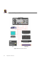
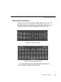
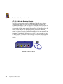
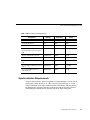
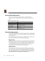
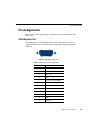
Digital News Production
Site Preparation Guide
N EWS E DIT
DIGITAL NEWS PRODUCTION
Contents
DNP System Layouts . . . . . . . . . . . . . . . . . . . . . . . . . . . . . . . . . . . . . . . 2
Digital News Production Layout (NewsEdit specific) . . . . . . . . . . . . . 2
Digital News Production (DNP) Workgroup Layout . . . . . . . . . . . . . . 4
DNP Server Connectors . . . . . . . . . . . . . . . . . . . . . . . . . . . . . . . . . . 5
External I/O Connections . . . . . . . . . . . . . . . . . . . . . . . . . . . . . . . . . . 9
ATI All-In-Wonder Breakout Module . . . . . . . . . . . . . . . . . . . . . . 10
Cabling Guidelines. . . . . . . . . . . . . . . . . . . . . . . . . . . . . . . . . . . . . . 11
Audio Mixer for NewsEdit . . . . . . . . . . . . . . . . . . . . . . . . . . . . . . . . . . . 13
Component Weights and Dimensions . . . . . . . . . . . . . . . . . . . . . . . . . 15
Site Requirements . . . . . . . . . . . . . . . . . . . . . . . . . . . . . . . . . . . . . . . . 16
Power Requirements . . . . . . . . . . . . . . . . . . . . . . . . . . . . . . . . . . . . 16
Synchronization Requirements . . . . . . . . . . . . . . . . . . . . . . . . . . . . 17
Environmental Requirements. . . . . . . . . . . . . . . . . . . . . . . . . . . . . . 18
Networking Requirements . . . . . . . . . . . . . . . . . . . . . . . . . . . . . . . . 18
Fibre Channel . . . . . . . . . . . . . . . . . . . . . . . . . . . . . . . . . . . . . . . 18
Ethernet Switch . . . . . . . . . . . . . . . . . . . . . . . . . . . . . . . . . . . . . . 18
Pin Assignments . . . . . . . . . . . . . . . . . . . . . . . . . . . . . . . . . . . . . . . . . . 19
VGA Monitor Port. . . . . . . . . . . . . . . . . . . . . . . . . . . . . . . . . . . . . . . 19
Keyboard and Mouse Connectors . . . . . . . . . . . . . . . . . . . . . . . . . . 20
RJ-45 Connectors . . . . . . . . . . . . . . . . . . . . . . . . . . . . . . . . . . . . . . 21
GPI Pin Assignments . . . . . . . . . . . . . . . . . . . . . . . . . . . . . . . . . . . . 22
This guide provides information about site requirements for installing Digital News
Production (DNP) systems. Electrical and physical specifications on the system
components are also included. Connector information as well as pin assignments are
given in case customized cabling is required.
Digital News Production
1
Digital News Production Site Preparation Guide
DNP System Layouts
This section provides a typical system layout. Diagrams of the Vibrint system
components identify the rear interface connectors. The exact orientation of the
equipment depends on:
• Available space in the work area — This document provides the dimensions
of the equipment, however, Grass Valley Group recommends additional space
for access and ventilation.
• Length of the cables — Cables with excessive length clutters the area and is
not recommended.
• User preference — Whether the monitor, video deck, and system are on the left
or the right side is up to the user. The order from top to bottom in the rack can
also differ to to accessibility of the connectors and viewing indicators.
Digital News Production Layout (NewsEdit specific)
Figure 1 shows all standard and optional components. Set up your system
components in positions that give you easy access to them.
Figure 1. DNP System Components (example is NewsEdit)
2
Digital News Production
Digital News Production Layout (NewsEdit specific)
The following is a list of supplied DNP Server system features:
• 20 gigabyte IDE hard drive with NTFS format for operating system
• 3.5 inch floppy drive; reads and writes to 1.44 MB diskettes
• CD-ROM reader; required for installing software
• Built-in TCP/IP compatible Ethernet LAN connection
• Windows2000 operating system
• Breakout I/O panel (2 options: Pro Analog or Pro D&A)
• Standard keyboard and PS/2 mouse
• Two serial ports
• DNP software
The following is a list of optional DNP Server system features:
• High resolution 17 inch VGA monitor
• Fibre Channel network adapter card
• Gigabit Ethernet adapter card
• Time-code Reader adapter card (FeedClip only)
• 9, 18, 36, 72 and 180 gigabyte removable SCSI media drives
• Additional DNP software
• Fibre Channel RAID3 protection storage
Digital News Production
3
Digital News Production Site Preparation Guide
Digital News Production (DNP) Workgroup Layout
Figure 2. DNP Workgroup Layout
4
Digital News Production
DNP Server Connectors
DNP Server Connectors
The DNP Server is a computer with specific peripheral hardware for converting
the incoming video and audio, analog or digital signals into digital format for
storage. The Windows2000 operating system and DNP application are
preinstalled on the DNP Server.
Figure 3 and Figure 4 identifies the rack mount version connectors and parts.
Table 1 provides a description of each connector.
Figure 3. DNP Server Back
Digital News Production
5
Digital News Production Site Preparation Guide
Table 1. DNP Server Connections
Number
6
Connector
Function
1
PS/2 style
PS/2 style connector for Mouse
2
RJ-45
Ethernet Port Connector
3
DB-25
Not used
4
DB-15
Not used
5
S-Video In
Video Input for VGA video
6
RCA
Not used
7
S-Video Out
Not used
8
1394 Firewire
Not used
9
PS/2 style
PS/2 style connector for Keyboard
10
USB
Disabled
11
DB-15 HD
VGA port (only used for troubleshooting)
12
DB-9 Male
COM1 port used for external GPI
13
RCA Mini
Computer audio line in (not used)
14
RCA Mini
Computer audio line out (not used)
15
RCA Mini
Computer Mic (not used)
16
DB-15 HD
VGA port used for external UI monitor
17
DB-9 Male
RS-422 Remote Control
18
Dual SC type
Fibre Channel connectors
19
50 pin SCSI
SCSI connector for external storage devices
20
Digital Tether
Connection to I/O Breakout panel
21
DB-9 Male
COM2 port used for external GPI
Digital News Production
DNP Server Connectors
Figure 4. DNP Server Front
Table 2. DNP Server Connections
Number
Function
1
Main power switch
2
Panel door lock
3
Keyboard lock
4
Reset power switch
5
1.4 meg Floppy disk drive
6
CD-Rom drive
7
Media drive lock
8
Media drive carriage #1
9
Media drive carriage #2
Digital News Production
7
Digital News Production Site Preparation Guide
Figure 5. DNP Server System connections
8
Digital News Production
External I/O Connections
External I/O Connections
The DNP Server comes with an I/O Breakout Box (BOB) to provide video and
audio input and output. Currently there are 2 different types of I/O panel
configurations. Figure 6 identifies the connections for the Pro Analog and Figure
7 identifies connections for the Pro Analog/Digital combination panel.
Figure 6. Pro Analog Breakout Box
Figure 7. Pro Analog/Digital Breakout Box
Note: On the backside of the Pro Analog/Digital breakout panel, is a
reference input for genlocking the DNP system.
Digital News Production
9
Digital News Production Site Preparation Guide
ATI All-In-Wonder Breakout Module
The DNP is equipped with an ATI All-In-Wonder Video Graphics Adapter.
Along with this adapter is a small purple breakout module for getting lowresolution video display on the user interface. The module connector inputs are
S-Video, RCA video and RCA audio. When using the Pro Analog I/O, you need
to connect the S-Video output from the I/O panel to the S-Video input on the ATI
module. When using the Pro Analog/Digital I/O, you need to connect the
composite video output of the I/O panel to the RCA video input on the ATI
module. Alternately, you can connect the video input of the ATI module to the
Component Y output of the I/O panel to see video. In any case, when you open
the DNP program, you need to set the VGA input selection in order to properly
see a video connection on the user interface. Figure 8 shows the ATI breakout
module.
Figure 8. ATI Breakout Module
10
Digital News Production
Cabling Guidelines
Cabling Guidelines
The customer is responsible for all video, audio, network and serial cables.
Lengths are determined by the customer's needs. A floor plan of the facility, with
the locations marked where the users and equipment are located, will help
determine cable requirements. Table 3 describes all cables typically needed, as
well as cable length limitations and recommendations.
• Use all GVG supplied cables delivered with the DNP system. All supplied
cables are tested and qualified for GVG broadcast system configurations.
• The monitors should be within 6 feet of the DNP server. VGA cable
extensions may be used although greater distances can degrade images
displayed on the monitors
• The keyboard and mouse should be within 6 feet of the DNP server. Keyboard
and mouse extensions may be used for greater distances.
• The video and audio breakout panel should be within 10 feet of the DNP
server.
• The VTR should be within 15 feet of the DNP server for a standard RS-422
length cable. An extension cable can be added for greater distances.
• The length of a fibre-optic cable between a DNP server and a fibre-channel
switch should be 1650 feet (500 meters) when using a 50-micron cable.
Digital News Production
11
Digital News Production Site Preparation Guide
Table 3. System Cable descriptions - Grass Valley Supplied
Cable Description
Length
Connects
Standard power cords
Up to 6 ft. (1.8m)
All physical hardware with
designated power supply
Keyboard cable
Up to 6 ft. (1.8m)
(Quality PS/2 extender cables can be used)
Keyboard to Server
Mouse cable
Up to 6 ft. (1.8m)
(Quality PS/2 extender cables can be used)
Mouse to Server
Digital tether data cable
15 ft. (1.8m)
I/O Breakout box to video board
on Server
Purple ATI I/O cable
8 ft. (1.8) standard
ATI I/O to mini din connection on
graphics card
S-Video cable
6 ft. (1.8m)
S-Video on Analog I/O box to ATI
I/O
Table 4. System Cable descriptions - Customer Supplied
Cable Description
12
Length
Connects
Fibre optic
50-micron, SC Multimode type, up to 1650
ft. (500m)
Fibre channel switch to server
fibre port
RJ-45 Cat5 Ethernet
Customer desired
Ethernet hub or switch to Server
ethernet port
Remote serial
Up to 15 ft. (4.6m)
(Quality RS422 extension module can be
used)
Remote control from VTR to RS422 card on server
BNC video
8 ft.
Digital I/O composite or
component Y to ATI I/O
BNC video reference
Customer desired
Reference on I/O Panel
BNC video
Customer desired
Customer equipment to I/O panel
BNC timecode
Customer desired
House timecode clock to TCR card
XLR Audio
Customer desired
Customer supplied equipment to
I/O panel
Digital News Production
Audio Mixer for NewsEdit
Audio Mixer for NewsEdit
As an option, a mixer can be added to enhance audio capabilities. This will allow
you to set up several inputs into the editor. Table 5 is a suggested configuration
on the setup of a mixer and NewsEdit. Examples used in the table are based on
the Mackie 1402VLZPro.
Table 5. Mixer Setup (Optional)a
Input
Analog Audio
with a Mixer
From
To
Cable type
VTR Channel 1 output
Mixer channel 1 line IN
XLR-female to 1/4”-male
VTR Channel 2 output
Mixer channel 2 line IN
XLR-female to 1/4"-male
Main mixer out left
channel
Breakout panel balanced
IN left channel
XLR-female to XLR-male
Main mixer out right
channel
Breakout panel balanced
IN right channel
XLR-female to XLR-male
Breakout panel Balanced
Left Out
VTR Channel 1 input
XLR-male to XLR-male
Breakout panel Balanced
Right Out
VTR Channel 2 input
XLR-male to XLR-male
Breakout panel
Unbalanced Left Out
Left desktop speaker
RCA-male to XLR-male or
1/4” male
Breakout panel
Unbalanced Right Out
Right desktop speaker
RCA-male to XLR-male or
1/4” male
Digital News Production
13
Digital News Production Site Preparation Guide
Table 5. Mixer Setup (Optional)a
Input
Analog Audio
without a Mixer
Digital Audio
Video
14
From
To
Cable type
VTR Channel 1 output
Breakout panel balanced
IN left channel
XLR-female to XLR-male
VTR Channel 2 output
Breakout panel balanced
IN right channel
XLR-female to XLR-male
Breakout panel Balanced
Left Out
VTR Channel 1 input
XLR-male to XLR-female
Breakout panel Balanced
Right Out
VTR Channel 2 input
XLR-male to XLR-female
Breakout panel
Unbalanced Left Out
Left desktop speaker
RCA-male to XLR-male or
1/4” male
Breakout panel
Unbalanced Right Out
Right desktop speaker
RCA-male to XLR-male or
1/4” male
VTR AES/EBU
Channels 1&2 Output
Breakout panel AES/EBU
Channels 1&2 Input
XLR-male to XLR-male
Breakout panel
AES/EBU Channels 1&2
Output
VTR AES/EBU Channels
1&2 Input
XLR-male to XLR-female
Breakout panel
Unbalanced Left Out
Left desktop speaker
RCA-male to XLR-male or
1/4” male
Breakout panel
Unbalanced Right Out
Right desktop speaker
RCA-male to XLR-male or
1/4” male
VTR-SDI Output
Breakout panel SDI Input
Single BNC-BNC
Breakout panel SDI
Output
VTR SDI Input
Single BNC-BNC
VTR Compoiste Output
Breakout panel Composite
Input
Single BNC-BNC
Breakout panel
Composite Output
VTR Composite Input
Single BNC-BNC
VTR Component Output
Breakout panel
Component Input
Tri BNC-BNC harness
Breakout panel
Component Output
VTR Component Output
Tri BNC-BNC harness
Digital News Production
Component Weights and Dimensions
Table 5. Mixer Setup (Optional)a
Input
Ethernet & Fibre
From
To
Cable type
Server Chassis
Ethernet Hub/Switch
RJ45-RJ45
Server Chassis
Fibre Channel Switch
Dual SC-Dual SC
a. For optimum performance and a clean cabling environment, it is recommended to keep
all cable lengths between 6-8 feet.
Component Weights and Dimensions
Table 6 describes some additional information regarding each DNP system's
physical specifications including weight and dimensions.
Table 6. DNP Physical Specifications
Component
Rack Mount
Rack Units
Height x Width x
Depth
Weight
DNP Server
Yes
4
5.87 x 17 x 20 in
40 lbs
Analog Breakout Box
Yes
2
3.5 x 12 x 3.8 in
2.5 lbs
D&A Breakout Box
Yes
3
3.7 x 13.68 x 4.25 in
3.5 lbs
17" Monitor (optional)
No
N/A
16 x 16 x 17 in
38 lbs
Mackie 1402VLZ Pro (optional)
Yes
8
2.9 x 14 x 12.9 in
9.5 lbs
Speakers (optional)
No
N/A
7.25 x 4.67 x 6.58 in
3.7 lbs
Brocade Silkworm 2400
(optional 8 port)
Yes
1
1.71 x 16.87 x 17.72
in
17 lbs
(dual
power
supply)
Brocade Silkworm 2800
(optional 16 port)
Yes
2
3.5 x 16.87 x 17.72
in
28.5 lbs
(dual
power
supply)
Netgear FS516 Ethernet Switch
(optional 16 port)
Yes
1
1.7 x 13 x 8 in
4.7 lbs
Digital News Production
15
Digital News Production Site Preparation Guide
Site Requirements
This section describes the various site requirements for installing the
NewsRoomSuite.
Power Requirements
Grass Valley Group highly recommends using a surge protector and an
uninterruptible power supply (UPS). If the computers lose power even for a
moment, the entire system will stop functioning. There must be a 20 A, 110 to
120 V alternating current, 60 Hz or 10 A, 220 to 224 V alternating current, 50 Hz
circuit breaker and an isolated ground.
Storage upgrades might require additional electrical service. Take into
consideration the equipment nameplate ratings when addressing this concern.
Consult your GVG representative.
Systems are designed to work with a single-phase (three-wire) power cord with a
grounded neutral conductor. To reduce the risk of electric shock, always plug the
cord into a powered off grounded power outlet.
Table 7 lists the power requirements for individual system components. Surge
protectors and a UPS are recommended but are not supplied by GVG.
For best performance, keep all system power connections on the same power feed
distribution panel. Do not connect any other equipment to the same outlet that is
powering the DNP equipment.
16
Digital News Production
Synchronization Requirements
Table 7. DNP System Power Requirements
Component
Voltage
Frequency
Power
DNP Server
120/240 VAC
50/60
300 Watts
Analog Breakout Box
N/A
N/A
N/A
D&A Breakout Box
120/240 VAC
17" Monitor (optional)
Specifications based on a Viewsonic
A70
100/240 VAC
50/60
2 Amps
Mackie 1402VLZ Pro (optional)
120/240 VAC
50/60
25 W
Fostex Speakers (optional)
120 VAC
Brocade Silkworm 2400 (optional 8
port)
100/240 VAC
50/60
1.5 Amps
Brocade Silkworm 2800 (optional 16
port)
100/240 VAC
50/60
1.5 Amps
Netgear FS516 Ethernet Switch
(optional 16 port)
100/240 VAC
50/60
29 W
1.5 Amps
5W
Synchronization Requirements
A stable video reference source is required for synchronizing the system only if
playing that system directly to air. The system needs no reference as a standalone workstation or on a fibre channel network environment. The Pro Analog
breakout box has reference In to the system on the front of the panel. The Pro
Analog/Digital breakout box has reference IN on the back of the panel.
Digital News Production
17
Digital News Production Site Preparation Guide
Environmental Requirements
Table 8 lists the environmental specifications for a standard broadcast
environment. The air conditioning must maintain the operating temperature
listed.
Table 8. Environmental Specifications
Condition
Range
Operating temperature
50 to 75 degrees Fahrenheit
Storage temperature
0 to 140 degrees Fahrenheit
Relative humidity
20% to 80%
Altitude
0 to 6000 ft (0 to 1829 m)
Networking Requirements
Grass Valley Group products are designed to work over industry-standard local
area networks (LANs) and wide area networks (WANs), using standard TCP/IP
networking protocols.
Install all possible network cabling before the equipment arrives. Make note of
all the network IP addresses that will reside within workgroup.
Fibre Channel
The DNP system transfers the final story(s) to the playback server through a Fibre
Channel switch connection. GVG recommends the Brocade Silkworm 2800
switch. Typically, fibre- optic cable is run along or inside a facilities ductwork
using using 50 micron dual SC type termination connectors. GVG can
recommend sources for custom or off-the-shelf length cables.
Ethernet Switch
The Ethernet hub or switch routes data between all DNP systems, the playout
server and newsroom systems. Ethernet hubs have multiple RJ-45 connectors
that connect all the network devices. A 100-BaseT Ethernet hub is required when
connecting within GVG newsroom production workgroups. Typically, status
LEDs on the hub shows valid connections or network activity.
18
Digital News Production
Pin Assignments
Pin Assignments
The following section provides pin assignments for various connections to the
DNP server.
VGA Monitor Port
The monitor port is a standard DB-15 pin female VGA connector for the 17"
graphics monitor. Figure 9 and Table 9 show the pin-out configuration for the
connector.
5
1
15
11
Figure 9. VGA Monitor Connector
Table 9. VGA Connector Pin Assignments
Pin
Signal
1
Red video
2
Green video
3
Blue video
4
GND
5
Display Data Channel GND
6
Red GND
7
Green GND
8
Blue GND
9
Not used
10
SYNC GND
11
GND
12
Serial Data
Digital News Production
19
Digital News Production Site Preparation Guide
Table 9. VGA Connector Pin Assignments
Pin
Signal
13
Horizontal SYNC
14
Vertical SYNC
15
Serial Clock
Keyboard and Mouse Connectors
The DNP system provides two standard PS/2 style connectors. These connectors
are used for the keyboard and mouse. Figure 10 and Table 10 show the pin-out
for these 6-pin female connectors.
5
6
3
4
2
1
Figure 10. PS/2 Connector
Table 10. PS/2 Connector Pin Assignments
Keyboard/Mouse Pin
20
Digital News Production
Signal
1
Data
2
NC
3
Ground
4
Plus 5 volts
5
Clock
6
Not used
RJ-45 Connectors
RJ-45 Connectors
Category 5 unshielded twisted pair (UTP) cable supports up to 100 megabits per
second. The cable contains four twisted pairs of wires, for a total of eight wires.
The four pairs of wires in UTP cable are color-coded so that they can be identified
at each end of the cable. Typically, the pairs are made up of a solid color and the
same color striped with white. The standard pin configuration for an 8-pin RJ-45
connector is shown in Figure 11.
8
1
Figure 11. Category 5, RJ-45 Connector
Table 11. RJ-45 Connector Pin Assignments
Pin
Color Code
1
Orange/white stripe
2
Orange
3
Green/white stripe
4
Blue
5
Blue/white stripe
6
Green
7
Brown/white stripe
8
Brown
Digital News Production
21
Digital News Production Site Preparation Guide
GPI Pin Assignments
There are 2 COM port connectors on the backplane of the DNP sesrver. COM1
is located alongside the other motherboard connectors. COM2 is located in a slot
position next to the video capture card(s). Both COM ports are generally used for
the NewsQ application but can also be used with NewsEdit. See the User Manual
for setting up the GPI Commands in relationship to the pins described inTable 12.
Figure 12. GPI DB-9 Connector
Table 12. GPI Pin Assignments
Pin
COM1 Function
COM2 Function
1
-
-
2
-
-
3
-
-
4
-
-
5
Chassis Ground
Chassis Ground
6
IN 2
IN 5
7
+12V
+12V
8
IN 1
IN 4
9
IN 3
IN 6
Provide +5 to +24 volts to an input to trigger.
22
Digital News Production
GPI Pin Assignments
For further information on third party products, please refer to the vendor’s
websites:
www.brocade.com
www.netgear.com
www.mackie.com
www.ati.com
www.fostex.com
www.microsoft.com
www.intel.com
Digital News Production
23