1
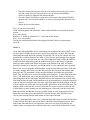
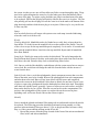
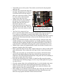
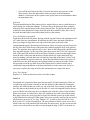
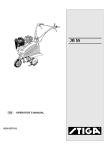
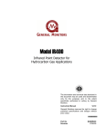
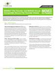
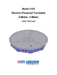
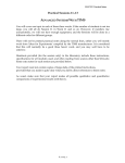
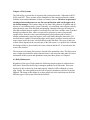
Chapter 6 Fish Systems
The fish facility at present has 10 separate fish system between the 3 laboratories H221,
J083b, and G617. These systems are the foundation of the research performed with the
fish they house and maintenance of them is of utmost concern. Therefore no personnel
should perform maintenance on any fish system filtration with out the approval of
the facility manager. The systems range in size from 1000 gallons to 30 gallons and all
but one is a recirculating water system. Generally, a recirculating water system works by
taking drainage water from fish tanks and pumping it through some type of biological
filter that contains bacteria capable of removing toxic fish waste, next the water is pushed
through a mechanical filter, often woven nylon or polyester to remove large mostly
organic debris, then the water is passed through activated carbon media to remove
smaller predominately non-polar organic waste, and finally through a ultraviolet (UV)
sterilizer that is capable of neutralizing algae, mold, spores, protozoa, bacteria and even
some viruses before the water is delivered back to the fish tanks. The types of and sizes
of these filters depend on the size and style of the fish system. As a general rule of thumb
the biological filter is placed where the water is dirtiest and the UV is located where the
water is the cleanest.
The one non-recirculating fish system is located in the quarantine room. This fish system
uses a single-pass method to insure fish tank water is not reused in other tanks. For more
information on this system and quarantine room procedures please see Chapter 9.
6.1 Daily Maintenance
Regardless of the type of fish systems the following categories must be addressed on a
daily basis. Water must be flowing in adequate quantities to all fish tanks. This water
needs to be able to drain out of the tank properly either by baffle, bulkhead or screen
plug. Finally, the water quality must be with in specific parameters and if not it must be
adjusted. The intent of this chapter is to show people how this can be done on all of the
different types of fish system found in the facilities.
6.2 Aquatic Habitats
General
In the H221 laboratory the Aquatic Habitat Fish System (AH) occupies the entire northwall. It is composed 5 5’-AH racks, 4 3’-AH racks and 2 4’-Zebrafish modular units
(Marine Biotech). It has a total water capacity of 3730 L (927 gal.) with available tank
sizes of 1.5 L, 2.0 L (Zmod only), 2.8 L, and 9.0 L. The 2.8 L and 9.0 L tanks are
interchangeable as are the 1.5 L tanks with the appropriate manifold. All fish tank water
lines have individual adjustment valves on the manifolds above the tank. The total
number of tanks varies greatly depending on the tank sizes and arrangements being used,
but it commonly supports 350-400 tanks. AH tanks must be used with appropriate lids
and baffles.
A 2 HP Baldor pump draws water from the sumps and delivers it to two canister bag
filters. The first canister is a particle prefilter with a 50 micron felt bag filter, the second
canister is a 50-micron bag filter with carbon and coral media. Water is then sterilized by
a 390 watt UV (6-65 watt bulbs) before entering the fish tanks. Water from the fish tanks
drain down a gutter and passes through a polystrand filter before entering the sump below
the fish rack. Water in the sump
J
K
M
moves through a Siporax biological
H
G
filter and is aerated by diffuser
I
powered by an air pump above the
canister filters, see figure 6.0. Water
D
is then drawn back to the pump. The
system generally runs at 35-45 gpm.
E
F
The system receives a 5% water
exchange (~50 gallons) from the
C
water tower every day via a timer,
metering pump, and solenoid valve
A
system located next to the water
B
tower. The timer turns on at 10:00
Figure 6.0 A) Valve connecting the sump to the pump.
AM off at 12:00 PM.
Maintenance
B) Pump C) Valve to prevent back flow during pump
replacement. D) Canister shut off valve #1 E) Prefilter
canister. F) Carbon filter canister. G) System bypass
valve. H) Canister shut off valve #2. I) Filter bypass
valve. J) Low-level pump shut off relay box. K) Air
pump platform. L) Pressure gauge. M) Pump power
switch.
Daily
Water Flow and Drainage. On a
daily basis individual tanks are
inspected by staff to insure adequate water flow and proper drainage. Smaller tanks (1.5
L-2.8 L) have a single water line while larger 9.0 L tanks have two. Each tank needs a
water exchange of 6 turns an hour (6 times the water volume of the tank). This can be
accomplished by adjusting the tanks water supply valve(s) to a steady but not brisk
stream of water. Brisk streams of water can overflow the tank possibly leading to fish
loss. Tanks with too little or no water supply can produce toxic levels of waste. Baffles
located at the back of the tank need to be inspected for excessive biofluc buildup that can
inhibit drainage. If the tank baffle is clogged lift the back of the fish tank lid (avoid
startling the fish) and with the baffle still seated at the bottom of the tank wiggle the top
of the baffle front to back. If this does not clear the debris switch out/install a new tank,
see Tank Use below.
Sumps. Also on a daily basis top off sumps with system water each sump is marked
indicating where the water level needs to be.
Lids. Once a week the lids should be wiped down with 70% isopropyl alcohol. Spray
isopropyl on to a paper towel and clean the fish tank lid. Be careful not to push any of the
debris on the lid in to the tank.
Weekly
Canister and sump filters along with carbon media need to be replaced weekly.
Maintenance is typically performed with the system running.
Sump Filters
Sump prefilters are located just below the vertical
L drainpipes on each rack and are
suspended above the sump water by a shelf. They are collected by pulling out and lifting
them off the filter shelf. The dirty filters are then placed in a labeled disinfection bucket
see disinfecting filters at the end of this chapter. Obtain clean sump prefilter pads from
the shelve above the sink and place them back on to the sump filter shelf. Make sure they
are situated under the draining water from the fish rack.
Canister Maintenance
o Just before maintenance record on the maintenance log the pressures from gauge
1,2, and 3 and the reading from the flow meter, all of which are labeled.
o Make sure the filter bypass valve (I) is completely opened.
o Slowly and simultaneously close the two canister shutoff valves (D and H). Make
sure that the pressure gauge (L) does not exceed 25 pounds per square inch (psi)
while closing these valves.
o Open the air breath knobs located on the tops of both canisters lids (bronze color
with black knob).
o Attach a plastic hose to the barbed outlet with valve at the bottom of either
canister. Place the other end of the hose in to an empty bucket.
o Open the barbed outlet valve. Water from the canister should drain in to the
bucket. If not tilt the bucket and plastic hose down towards the ground. Water
drains from the canister by gravity. If this still does not work try turning the
canister lid counter-clockwise (open) to relieve any pressure.
o Drain the second canister. Open both canister lids by turning them counterclockwise. As the lids comes off be careful not to loose the large black o-ring
under each lid.
o Set the lids and o-rings aside for the time being, and empty the drainage bucket.
o With the freshly emptied bucket nearby and lift out to the bag filters inside the
canisters and place them in to the bucket. With plastic hose still connected to the
o
o
o
o
o
o
o
o
opened barbed valve briefly rinse out both canister with RO and take the soiled
filters to the sink.
Lift out the carbon and coral media bags out of the canister bag filters. Place the
canister filter bags in to disinfection buckets see filter disinfection. Empty the
carbon in to the garbage can and wash off both the empty carbon bag and the
coral bag with the coral still in it.
Obtain a bucket of fresh carbon from H225 and get the carbon strainer bucket
(short white bucket with numerous holes drilled through it). Inside the strainer
bucket there is a horizontal line fill the strainer bucket with fresh carbon to this
mark. Set the strainer bucket in to the sink and thoroughly rinse the carbon with
RO water. Allow to dry somewhat in the sink.
Collect two new bag filters from above the sink. Place one each into each canister.
Get a large funnel and place it in the second (F) canister, the carbon media one.
Pour the washed carbon from the strainer bucket through the funnel in to the bag
filter. Place rinsed coral bag back in to the canister.
Clean the canister lids with 70% isopropyl and a paper towel. Wipe off o-rings
with a paper towel and relubricate them with Teflon lubricate. Place the one ring
in the groove inside the canister just inside the threaded portion at the top. Repeat
for the second canister.
Set the canister lids back on top and turn them clockwise until they are snug.
Hand tight will be sufficient.
Make sure the barbed drain valves at the base of each canister are closed and the
air breathers are still open. Slowly and simultaneously open the two canister
shutoff valves (D and H). As water rushes in to the canisters displaced air will
whistle out the breathers. When the whistling stops turn the air breather knobs
clockwise to close them. There will also be whistling noise from the pressure
relief valve (not shown), which is above and to the left of the canisters. This is
normal.
Slowly close the filter bypass valve (I) until the pressure gauge (L) reads 15 psi.
Record the maintenance procedures in the maintenance database on the H225
computer. Also, under comments on the water quality sheet hanging on the fish
system rack write “maintenance”.
Every Six Months or as needed
Clean out drain gutters and manifolds. Gutters and manifolds are removable from this
system. Remove Siporax biofilter panels from the sumps and rinse them off with RO.
Every Nine Months
Replace U.V. bulbs. System has U.V. controller box that has illuminated indicator of bulb
function and timer, see directions U.V. at the end of this chapter.
Every Year or as needed
Disinfect shelves with isopropyl alcohol. Have the system pump serviced at a motor
shop.
Tank Use
A
Clean tanks, lids and baffles can be found along side and above the sink in H221. There
are two types of baffles. The blue ones are for large adult fish ~90 days old while the
transparent ones with the mesh screening are for younger fish. The blue baffles sit off the
bottom of the tank when installed, so if the fish are small enough to go through this gap
or if you’re uncertain, use the transparent baffle. These baffles sit flat across the bottom
of the tank, no gap. Slide the baffle in to the back of the tank making sure the baffle sits
freely on to the bottom of the tank. The transparent baffles have a groove on the outside
edge that needs to face the back of the tank. Make sure these baffles slide all the way
down to the bottom of the tank. Both types of baffles should fit smoothly in to the tank,
you should not have to use significant force to install them if you are your probably
installing them wrong, and should ask for help. If your putting fish in the tank fill it ¼
full with system water, and place the fish in to the water. Place or transfer any identifying
labels to the front upper left hand corner of the tank and create a small white label with
date the tank was installed on to the system and place it on near the bottom left corner of
the tank. Install the lid it sits down slightly with in the tank so that the lid is flush with the
rest of the tank. The tabs/handles should fit over the side of the tank. The bottom outside
of the tank has 2 sets of cleats that fit over the steel bars of the fish rack. Lift the tank in
to place making sure the drainage pipe rests above the drain gutter and the cleats are
parallel and rest over the supporting steel bars. Install the water line(s) in to the small
hole in the lid near the front. Open the water valve(s) until a steady but not brisk stream
of water enters the tank.
To clean a tank shutoff the water valves and remove them from
the tank. With the tank still in place lift the front of tank to drain
water out the back of the tank. Additional water can be removed
from the tank if need be by siphoning with a rubber hose with a
screen attached to the intake to prevent fish from being sucked
up. Water from the siphon can be drained in to a bucket, and
emptied in to the sink. Lift the tank up high enough to clear the
gutter at the back and pull out the tank. Transfer the fish to a
clean tank as described above. Take the dirty tank to the sink
remove the lid and baffle and empty out any remaining water.
Thoroughly rinse the tank and accessories with RO water, and
place it in the bleach bath or on the dirty dish cart.
Adjusting Water Quality
The following is also posted on a green tag hanging on the fish
system rack.
To adjust pH: pH> 6.95, no adjustment needed
pH: 6.95 > pH > 6.75, add 300 ml 1 M sodium bicarbonate
solution
pH: pH < 6.75, add 400 ml 1 M sodium bicarbonate solution
Figure 6.1 A)
Aquatic habitat tank
with adult baffle
properly installed. B)
AH tank properly
installed on fish rack.
To adjust Conductivity: 1500 µs, no adjustment needed
Conductivity > 1700 µs, 100 gallon RO water exchange
Conductivity < 1300 µs, add 200 ml super saturated salt solution to the sump.
The AH system has an overflow drain. To perform a manual water exchange to bring
down the conductivity slowly overfill the sump to the desired volume with RO water.
The flow rate of the RO water will need to be known and the water exchange has to be
timed.
Safety Features & Emergency Shutdown
The AH system has a float-switch pump shutdown in the sump adjacent to the pump that
is controlled by the black relay box (I in Figure 6.0) located just above the filter canisters.
During times of low water levels in the sump the pump will shut down to avoid drawing
air in to the pump that could lead to gas-bubble disease in the fish. For this system to
work the pump has to be plugged in to the relay box and the float switch needs to be
properly adjusted, set to shut off before the water level in the sump reaches the intake of
pump. In tandem with this feature is the auto-fill system that is driven by the system
water tower pump and controlled by a float switch in the sump adjacent to the pump. If
the water level in the sump drops the switch will open allowing the sump to fill with
system water from the tower. For this feature to work the water tower pump most be
running and the float switch needs to be properly adjusted. This system should be tested
periodically for proper function. For adjustments to these systems see the Aquatic
Habitats user manual located on the shelf in H225. In case of emergency the switch
located on the float-switch relay box can shut down the system. Warning, shutting down
the system will most likely flood the sumps to avoid this turn the overflow drain
downward. The drain is located across from the auto-fill float-switch downward.
6.3 Aquaneering
General
The current Aquaneering fish system (AQ) is in the J-083b next to the cement column to
the right as you enter the laboratory. This 170-gallon (653 Liter) 6-shelf stand-alone fish
system offers 1.5 L, 2.8 L and 9.0 liters tanks that are interchangeable on the rack (the 1.5
L tanks with appropriate manifold). The system typically holds 62 tanks, but this varies.
Most of the filtration package on this system is submerged. The AQ multirack system,
currently under construction, occupies the entire southeast section of J-083b lab and
when completed will have a total volume of 1008 gallons (3877 Liters) with 600 tanks of
various sizes (1’s, 3’s and 9’s). Each tank has individual water flow control valves on the
manifold above the tank.
AQ and AH fish systems are very similar to each other, even to the point were their tanks
can be interchanged between the two fish systems, but tank accessories (baffles and lids)
are not. For this reason it is not allowed to interchange tanks between the systems. AQ
fish tank accessories are green while AH are blue. Future expansion plans call for more
and larger multi-rack AQ systems.
Stand-Alone. Water is drawn in through 2 carbon filters wrapped
in10 µm Dacron in to the fish rack pump. From here the water is
pumped to the top of the rack where it is sterilized by a 40-watt
U.V. before entering the tank manifolds. Waste water drain out the
tanks into gutters and then through a 10µm Dacron pad in the
sump. From here a biofilter pump moves the water to the bottom
of a sand biofilter. The water up wells to the top of the biofilter
and passes on to the rack pump once again.
Multirack. This system filtration is generally broken up in to two
main sections influent and effluent filtering each with it own
Figure 6.2 J-083b
pump(s). Influent filtration starts with water being drawn by one or laboratory AQ
two ½ horse power system pumps, depending on the number of
Stand-Alone Fish
tanks in use, from the filtration sump to two canister filters each
System
housing micron bags with carbon. Water is then passed to a 200watt U.V. sterilizer before entering the fish tanks. Effluent filtration occurs as drainage
water from the fish rack sumps is drawn up by a ½ hp pump in to a large sand filter
(particulate and biofilter) that then drains in to a secondary biofilter before entering the
filtration sump.
Maintenance
Daily
See Daily Maintenance Aquatic Habitats. The only difference is that AQ tank can have
up to 3 parallel baffles setup in the back of the tank. If one gets clogged it can be
removed with the remaining baffles in place, so there is no need to drain the water down
in the tank helping to avoid fish loss. This feature can also be used with different sizes of
baffles adult, 750 µm and 500 µm that can be placed in parallel and removed as the fish
grow.
Weekly
Remove the Dacron pad filter suspended above the sump(s), and place it in a disinfection
bucket. Replace it with a clean pad from the shelf above the sink. Dirty pads can be
disinfected see disinfecting filters below or throw away if worn.
Monthly
Stand-Alone.
The carbon filters needs to be replaced monthly. To
replace the carbon, turn off the power to the rack pump.
Pull the filter housings from the pump intake manifold by
pulling straight out. Remove the Dacron mechanical filter
socks that are wrapped around the carbon filters and set it
A
B
C
aside for disinfection. Unscrew the caps from the
housings and pour the old carbon in to the trashcan.
Figure 6.3 A. Rack pump. B.
Thoroughly rinse the carbon filters off with RO water.
Biofilter. C. Biofilter pump.
Then invert a small beaker or wrap a paper towel over the
pipe running down the center of the housings to prevent carbon from entering the pump
intake pipe. Pour new carbon in to the housings and rinse them down with RO water to
remove any dust. Screw the caps back onto the housing and place a clean Dacron socks
back over the housings. Insert them back in to the rack pump intake manifold. Restart the
pump.
Multirack Canister Maintenance
o Record the pressure on both canisters before and after maintenance. Record this
information in to the maintenance database along with other relevant maintenance
notes following the entire maintenance process.
o On one of the two canister filters close the red valve just above the canister and
then close the red valve just below it.
o Connect a hose to the small blue canister drain valve near the bottom of the
canister, open the valve and drain the water in to a bucket or down a floor drain.
o Turn the canister lid lock ring counterclockwise until it is free from the canister
threads and remove it by lifting it off the canister lid. Then remove the canister
lid.
o Inside the canister, remove the canister strainer basket along with the felt canister
sock with the carbon bag inside. Pull the sock out of the strainer and clean it with
RO water. Pull the carbon bag out and empty it in to the trash. Refill the bag with
carbon and rinse off the carbon dust. Disinfect the dirty canister sock see below.
o Reinstall the canister strainer basket in to the canister, install a clean felt canister
sock in to the basket along with the rinsed carbon bag.
o Clean the threads on the canister. Remove the o-ring, wipe it off, relubricate it
with Teflon, and then reinstall it.
o Place the canister lids squarely back on to the canister and evenly press it down
over the o-ring. Place the ring lock down over the canister lid and turn it
clockwise until it is tight onto the canister threads.
o Close the drain valve halfway. Open the red valve above the canister first then
open the red valve below the canister. As soon as water breaches the drain valve
close it.
o Repeat for the second canister.
Every Six Months or as needed
Clean out drain gutters and manifolds. Gutters and manifolds are removable from this
system.
Every Nine Months
Replace U.V. bulbs see directions U.V. at the end of this chapter.
Every Year or as needed
The shelves should be disinfected with isopropyl alcohol. Have the system pump
serviced.
Tank Use
A
Clean tanks, lids and baffles can be found along side and above the sink in J083b. There
are three types of baffles the green ones are for large adult fish ~90 days old while the
transparent ones with the mesh screening 500 µm and 750 µm are for younger fish. The
green baffles sit off the bottom of the tank, so if the fish are small enough to go through
this gap or if you’re just uncertain, use one of the transparent baffles. Slide the baffle in
to the back of the tank making sure the baffle sits freely on to the bottom of the tank.
Make sure these baffles slide all the way down to the bottom of the tank. All baffles
should fit smoothly in to the tank, you should not have to use significant force to install
them if you are your probably installing them wrong, and should ask for help. If the fish
are small, younger than 30 days use the 500 µm in the first slot from the front the tank
then place the 750 µm behind it in the next slot behind it, and finally the green adult
baffle. This will allow us to remove the baffles as the fish grow. To place fish in the tank
fill it ¼ full with system water, and place the fish in to the water. Place or transfer any
identifying labels to the front upper left hand corner of the tank and create a small white
label with the date the tank was installed on to the system and place it near the bottom left
corner of the tank. Install the lid it sits down with in the tank so that the margin of the lid
is flush with the rest of the tank. The tabs/handles should fit over the side of the tank. The
bottom outside of the tank has 2 sets of cleats that fit over the steel bars of the fish rack.
Lift the tank in to place making sure the drainage pipe of the tank rests above the drain
gutter in the back and that the cleats are parallel resting over the supporting steel bars.
Install the water line(s) in to the small hole in the lid near the front. Open the water
valve(s) until a steady but not brisk stream of water enters the tank.
To clean a tank shutoff the water valves. With the tank still in place carefully lift the front
of tank to drain down the water out the back of the tank. Drain enough water out of the
tank so that when the tank is level again the water level is at least an inch below the
outflow drain, or enough water so that the tank can be easily lifted off the shelf. If need
be additional water can be removed from the tank by siphoning water with a rubber hose
with a screen attached to the intake of the siphon to prevent fish from being sucked up.
Water from the siphon can be drained in to a bucket, and emptied in to the sink. Lift the
tank high enough to clear the gutter at the back of the tank and pull the tank out. Transfer
the fish to a clean tank as described above. Take the dirty tank to the sink remove the lid
and baffle and empty out any remaining water. Thoroughly rinse the tank and accessories
with RO water, and place it in the bleach bath or on to the dirty dish cart.
Adjusting Water Quality
The following is also posted on a green tag hanging on the fish system rack.
To adjust pH: pH> 6.95, no adjustment needed
pH: 6.95 > pH > 6.75, add 25 ml 1 M sodium bicarbonate solution
pH: pH < 6.75, add 50 ml 1 M sodium bicarbonate solution
To adjust Conductivity: 1500 µs, no adjustment needed
Conductivity > 1700 µs, 25 gallon RO water exchange
Conductivity < 1300 µs, add 50 ml super saturated salt solution to the sump.
The AQ system has an overflow drain. To perform a manual water exchange to bring
down the conductivity slowly overfill the sump to the desired volume with RO water.
The flow rate of the RO water will need to be known and the water exchange has to be
timed.
Safety Features & Emergency Shutdown
The AQ system has a float-switch pump shutdown in the sump next to the overflow
drain. During times of low water levels in the sump the pump will shut down to avoid
drawing air in to the pump that could lead to gas-bubble disease in the fish. If the water
level drops in the tank due to low levels the switch will turn back on once water levels in
the sump rise again (fill the sump with system water). For this system to work the pump
has to be plugged in to the float switch itself at the electrical plug bank on the left side of
the system. The switch is adjusted by varying the tether length, the length of the cord
between the float and wherever the cord is tied off at (fixed). Longer cords will allow
larger changes in water levels without any disruptions to the power of the pump, short
cords will have a much narrower range. The tether length needs to be set to shut off
before the water level in the sump reaches the intake of pump (where the pump pulls in
water). This system should be tested periodically for proper function. In case of
emergency the switch located on the electrical plug bank can shut down the system. If the
system is shutdown water will rise in the sump and go out the overflow drain. When the
system is restarted system water will have to be added to the sump to make up for lost
water.
6.4 Zebrafish Modular
General
There are a total of 5 Zebrafish modular (Zmod) units in H221 and J083b. There is 3 4’
Zmods in H221. Two are connected to the Aquatic Habitat System there is another one in
this laboratory on the east wall next to the spawning rack, which is used to hold juvenile
fish 20-90 days old and hold test pairs of fish. Then there is a pair of 6’ 6 shelved Zmods
in J083b between the F1 and the Big fish system. The 4’ units are 70-gallon systems
while the 6’ Zmods are 110 gallons. The two in J083b are connected together for a total
of 220 gallons. Water is drawn from these systems by magnetic drive pumps (21’ max
head) and pushed through a Red Sea Ocean Clear biological filter with polystrand pad for
bacterial substrate. The water then enters an Ocean Clear 25-micron pleated cartridge
filter that also houses bags of carbon and coral filter media. Water then passes through a
40-watt Lifeguard U.V before being delivered to the tanks. The drainage system of
Zmods is unique in that they are a closed shelf system. The water drains out the front of
the tanks onto the shelf and then drain down the back wall of the system. Effluent then
passes through felt filter socks hung in the sump below. The systems mainly support 2 L
tanks, but also a few 4 L tanks. One 4’ unit holds 84 2 L tanks while 6’ system can
accommodate 126 2 L. The design of these systems make it easy to install and remove
tanks, just simply place the tank under the stream of water coming from the manifold.
Maintenance
Daily
Water Flow
Tanks are inspected daily to insure that there is adequate water flow. There should be a
steady stream of water entering the tanks. If the tanks across an entire shelf have low
water flows first check to see if filtration maintenance is needed. Dirty filters reduce
water pressure see monthly maintenance. If this is not the case, try adjusting the shelf
manifold valve located on the outside of the unit inline with the shelf. Individual tanks
might also experience low-flows. In this case it is likely that debris is blocking the water
outlet. Straighten a paper clip, and gently push in to the outlet and then back out repeat
this process until the water runs freely.
Drain Plugs
Drain plugs are inspected daily to insure that drainage
plugs are not blocked. There are 4 different sizes and
colors of drain plugs. Blue plugs 300 µm are rarely used
but are useful for fish that are moved off the nursery to
the Zmod but are still small. White plugs 700 µm are
typically used for fish just moved off the nursery at an
age of 20+ days. Orange 1/16” screens are used for fish
30+ days. Red screens 1/8” are used for adult fish. The
rule of thumb of which screen size to use is based on the
size of the smallest fish in the tank. Be conservative, use
Figure 6.4 Zebrafish modular
tanks with white drain plugs.
the screen size that you are sure will not allow any fish to escape through the plug. Plugs
need to be replaced anytime the water level in the tanks goes more than halfway above
the center of the plug. To replace a plug, hold the new plug in one hand next to the plug
to be replaced. Pull out the old plug and quickly slide the new one in to its place. You can
also partially pull out the old plug to lower the water level in the tank to the bottom of the
plug drain hole and then slide the new plug in to its place. Either way be very careful not
to loose any fish.
Sumps
Also on a daily basis top off sumps with system water each sump is marked indicating
where the water level needs to be.
Weekly
Flushing Manifolds. Manifolds need to be flushed on a weekly basis to keep them free
from debris. To do this locate the manifold valves on the outside of the Zmod. Close all
of the valves except for the top manifold open it completely. Let it run for 10 seconds and
then open the manifold below it and close the top manifold. Repeat until all manifolds
have been flushed.
L
Sump Socks. Weekly the sump socks need to be disinfected. The socks hang under the
Zmod effluent drain. Remove the dirty socks and replace them with clean ones from the
shelf above the sink. Disinfect dirty sock see disinfecting filters below.
Lids. Once a week the lids should be washed down with the system water hose to remove
excess feed. Be careful not to dislodge the tank lids from the tanks with the stream of
water from the hose.
Splash Guards. Once a week the splashguards, plastic transparent screens that cover the
front of the tanks, need to be cleaned. Remove the splashguards from each compartment
and take them to the sink. Rinse off any loose debris with RO water and completely
immerse the screens in the bleach bath. Allow them to bleach for one hour. Put on a pair
of gloves, remove the splashguards from the bath and place them in the sink. Thoroughly
rinse them off with RO water, generally 3 passes of water across each surface, and place
them on the shelf to dry for a while. Place the screens back in to the compartments. Do
not leave the splashguards off the system over night with out the screens in place.
Splashing water will create floods with out the screens in place.
Monthly
Once a month the pleated mechanical filter along with its carbon and coral media need to
be replaced. The following procedure should be performed at least monthly, or if the
pressure in the mechanical filter goes above 15 psi, or the pleated filter becomes visibly
dirty, or if the system exhibits prolong period of low pH.
o Record the pressure from the gauge located on the front of the micron mechanical
filter, before and after maintenance.
o Turn off the power to the system. The switches can be found on the plug bank
under the unit.
o Close the valve between the sump and
the pump. During this process keep an
eye on the water level in the sump to
make sure it does not overflow. If need
be a hose can be connected to the
E
sump to lower the water level.
D
o Attach a hose to the valve located at
C
B
the bottom of the mechanical filter.
Run the other end of the hose to a
floor drain. Open the valve.
A
o Open the air bleed valve (white dial)
on top of the lid of the filter. This will
Figure 6.5 J083b Zebrafish modular
allow the water in the canister to drain
system A. Sump B. Pump C. Biofilter D.
Mechanical Filter E. Ultraviolet sterilizer.
out.
o The filter lid is composed of two
pieces a clear lid (with air bleed valve) and a threaded knob ring lock lid (gray).
Use a mallet or small hammer to gently tap the knobs on the ring lock lid
counterclockwise until it loosens. Unscrew the lid completely and remove it along
with clear lid. Wash down both sides of the two lids with RO water in the sink
and set aside.
o Remove the pleated micron filter, carbon, and coral bags. Wash down the filter
with RO and place it in a disinfection bucket, see disinfecting filters. Empty the
carbon bag in to the garbage and place new carbon in the bag. Use RO water to
wash dust off the carbon and seal the bag with a plastic band. Wash down coral.
o With the filter canister still emptied briefly wash it out with RO, if need be use a
sponge to clean the sides of the canister.
o Place a clean filter back in to the filter canister being sure to center it on the round
white influent plate. Place carbon and coral bags in to the center of the pleated
filter.
o With a paper clip gently pry out the black o-ring just above the threads for the
ring lock on the canister housing. Wipe the o-ring off with a paper towel and
relubricate with Teflon lubricant. Reinstall the o-ring make sure it fits smoothly in
to the groove on the side of the canister.
o Place the clear lid back on to the canister. It should rest flat across the canister
with the edge of the lid fitting snuggly over the o-ring. Hand-tighten the ring lock
over the clear lid.
o Close the canister drain valve and detach the hose. Leave the breather valve open.
o Open the valve between the sump and the pump then turn on the power. The
canister will fill with water. Close the breather valve on the lid clockwise and
tighten when the water level reaches the lid.
o Once running use your hand to probe around the edge of the ring lock lid to check
for leaks. If a leak is detected try tightening the lid more if this does not work
follow the steps again to drain the canister and reset the lids.
o Clean off the shelf where the filter is located. Record the new pressure on the
filter canister. Enter this data and the entire procedure in the maintenance
database. Under notes on the systems water quality sheet write maintenance under
the appropriate date.
Quarterly
The polystrand biological filter pads need to be washed down to remove dead bacteria so
new bacteria can occupy the substrate. To do this follow the directions above using the
biological filter canister instead of the pleated micron filter. The biological pads are only
washed down not disinfected. Simply wash the pads down with RO water, leave one of
the pads unwashed (dirty) and reinsert them back in to the canister.
Every Six Months or as needed
Wash down drain wall and panels. Starting with the top shelf remove the splashguard and
all 7 tanks from one compartment. Wash down the shelf where the tanks resided next
place your finger in finger hole at the top of the white panel at the back of the
compartment then pull it downward and forward to release it from the tap-lock located on
the top of the shelf. Pull the top of the panel down while keeping the base of the panel in
place. The panel has three taps that fit in to the 3 holes in the bottom of the shelf that help
keep the panel aligned. Lay the top off the panel down on the shelf. This will expose the
back of the panel and the back-wall of the Zmod. With the system hose thoroughly wash
down the back of the panel and the back-wall then lift the top of the panel back in to
place by pushing it towards the back-wall until the front edge of the panel “clicks” back
in to place behind the tap-lock on the top. Wash down the shelf one more time, place all
tanks back on to the shelf and place the splashguard back in front of the tanks. Follow
this procedure from the top shelf down to the bottom shelf so debris from the top is
continually being pushed down to the drain and finally in to the sump sock. It may be
necessary to replace the sump sock after this maintenance see sump socks above.
Every Nine Months
Replace U.V. bulbs see directions at the end of this chapter.
Tank Use
Zmod tanks are composed of three parts the tank itself, a lid and a drain plug. There are
two different styles of tanks currently in the fish facilities. Older tanks are rectangular
and have lids with lids that rest on the very top of the tank. Newer tanks are tapered and
have lids that set down inside the top of the tank. It’s easy to distinguish between the two
types of lids because older ones have rectangular rods under the surface of the lid while
newer ones do not. As stated above, there are 4 different sizes and colors of drain plugs.
Blue plugs 300 µm are rarely used but are useful for fish that are moved off the nursery
to the Zmod but are still small. White plugs 700 µm are typically used for fish just moved
off the nursery at an age of 20+ days. Orange 1/16” screens are used for fish 30+ days.
Red screens 1/8” are used for adult fish. The rule of thumb of which screen size to use is
based on the size of the smallest fish in the tank. Be conservative, use the screen size that
you are sure will not allow any fish to escape through the plug. In H221 clean tanks are
stored above the nursery in J083b they are stored next to the Zmods under the big system.
Tank accessories are located next to the tanks. To set up a new tank obtain a clean one,
the appropriate size drain plug and proper lid. Fill the tank halfway full with clean system
water, place the fish and all identifying labels above or alongside the drain plug. Fish can
be placed in to the tank either by netting or by pouring. Place the lid on the tank. Find an
open space on the Zmod, remove the splashguard and place the tank on the shelf under
the water emitter. Place the splashguard back in front of the tanks.
Adjusting Water Quality
The following is also posted on green tags on the individual Zmod systems. There are
two different sizes of the Zmods covered here so make sure you use the water
adjustments for the appropriate sized system.
J-lab Zmod 210 gallon system
To adjust pH: pH> 6.95, no adjustment needed
pH: 6.95 > pH > 6.75, add 100 ml 1 M sodium bicarbonate solution
pH: pH < 6.75, add 150 ml 1 M sodium bicarbonate solution
To adjust Conductivity: 1500 µs, no adjustment needed
Conductivity > 1700 µs, 20 gallon RO water exchange
Conductivity < 1300 µs, add 100 ml super saturated salt solution to the sump.
H-lab Zmod 70 gallon system
To adjust pH: pH> 6.95, no adjustment needed
pH: 6.95 > pH > 6.75, add 25 ml 1 M sodium bicarbonate solution
pH: pH < 6.75, add 50 ml 1 M sodium bicarbonate solution
To adjust Conductivity: 1500 µs, no adjustment needed
Conductivity > 1700 µs, 5 gallon RO water exchange
Conductivity < 1300 µs, add 25 ml super saturated salt solution to the sump.
Zmods have spigots installed on their sumps. To perform a manual water exchange to
bring down conductivity attach a hose to the spigot and drain the water level down to the
desired volume and then refill the sump with RO water.
Safety Features & Emergency Shutdown
Zmods have a sump float-switch pump shutdown in the sump. During times of low water
levels in the sump the pump will shut down to avoid drawing air in to the pump that
could lead to gas-bubble disease in the fish. The switch will turn back on once water
levels in the sump rise again. For this system to work the pump has to be plugged in to
the float switch itself. The float needs to be set to shut off before the water level in the
sump reaches the intake of pump. In an emergency any Zmod can be shutdown via plug
bank switch attached to the rack underneath the system.