1
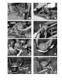
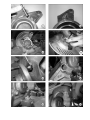
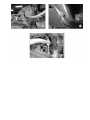
INSTALLATION INSTRUCTIONS
2102
LOWERING SPINDLE ASSEMBLY
1998-UP CHEVROLET / GMC BLAZER / X-TREME / JIMMY / ENVOY
2 Wheel Drive
Congratulations! You were selective enough to choose a BELLTECH PRODUCT. We have spent
many hours developing our line of products so that you will receive maximum performance with
minimum difficulty in installation.
This kit has been specifically engineered for the vehicles described above. Please note that this Belltech spindle kit
will lower these vehicles approximately 2-inches when used in conjunction with the OEM coil springs. When a greater
amount of lowering is desired, we recommend using only high quality Belltech lowering coil springs. We DO NOT
RECOMMEND cutting the OEM coils in order to achieve an increased drop. This spindle kit should be used with
unmodified OEM coils or 1, 2, or 3-inch Belltech lowering coils only.
In order to properly equip your truck and maintain predictable handling characteristics, we recommend installing
only high-quality Belltech components with this kit. We also suggest installing Belltech Anti-Sway Bars and NitroDrop® or Nitro-Active® shock absorbers to further improve your vehicle’s handling and performance. Check the
most current Belltech Application Guide for the proper part numbers recommended for your vehicle.
NOTE: Be aware that many automobile manufacturers often make running production changes throughout any given
model year. Therefore, some minor differences may exist between the information presented here and the actual
configuration present on your vehicle. It would be impossible to account for the multitude of minor running design
changes, and therefore, the installer must use his/her judgment and knowledge when performing this installation to
insure safe and proper function and performance of the vehicle when complete. If in doubt, please call our Technical
Assistance Department for further information.
WARNING:
DO NOT WORK UNDER A VEHICLE SUPPORTED BY ONLY A JACK. PLACE SUPPORT
STANDS SECURELY UNDER THE VEHICLE IN THE MANUFACTURER’S SPECIFIED
LOCATIONS UNLESS OTHERWISE INSTRUCTED.
WARNING:
DO NOT DRIVE VEHICLE UNTIL ALL WORK HAS BEEN COMPLETED AND CHECKED.
TORQUE ALL HARDWARE TO VALUES SPECIFIED.
RECOMMENDED TOOLS:
Properly rated floor jack, support stands, and wheel chocks
Internal Coil Spring Compressor w/safety chain
Lower ball-joint removal tool (Refer to factory Service Manual)
3/16” Allen™ key and male socket
Metric Socket Set / Metric wrench set
Small flat-bladed screwdriver
Medium weight ball-peen hammer
Angle grinder or die grinder equipped with cutoff wheel
15 inches of heavy gage wire
Interchangeable Head Torque Wrench with 9/16” Box-end Attachment: 10-100 ft.-lbs. range
Chassis grease or Anti-seize compound
Fast drying chassis black spray paint
Safety Glasses
! Note: It is very helpful to have an assistant available during installation.
! SAFETY REMINDER: PROPER USE OF SAFETY EQUIPMENT AND EYE/FACE/HAND PROTECTION IS
ABSOLUTELY NECESSARY WHEN USING THESE TOOLS TO PERFORM
PROCEDURES!
KIT INSTALLATION
As this is a relatively complex installation, we recommend that a qualified mechanic at a properly
equipped repair facility perform it. The use of safe and properly maintained equipment is very important!
1. Jacking, Supporting, and Preparing the Vehicle
a) Open the hardware kit and remove all the contents. Refer to the parts list (Page 7) to verify all
parts are present
b) Park the vehicle on a smooth, level concrete or seasoned asphalt surface and activate the
parking brake. Block the rear wheels of the vehicle with appropriate wheel chocks, making
st
sure the vehicle’s transmission is in 1 gear(manual) or “Park”(automatic). Loosen, but do not
remove, the front wheel lug nuts.
c) Using a properly rated floor jack, lift the front wheels of the vehicle off the ground. Place
support stands, rated for the vehicle’s weight, in the factory specified locations. Refer to the
vehicle Owner’s Manual. Prior to lowering the vehicle onto the stands, make sure the
supports will securely contact the chassis.
d) Slowly lower the vehicle onto the stands and, before placing the vehicle’s entire weight on
them, again check that they properly and securely contact the chassis as described above.
Check for possible interference with any lines, wires, cables, or other easily damaged
components. Remove the front wheels.
IMPORTANT NOTE: It’s imperative that the vehicle is properly supported during this installation to prevent
personal injury and chassis damage! Make sure that the support stands are properly placed prior to
performing the following procedures. We DO NOT RECOMMEND using wheel ramps while performing this
installation.
2. Front Brake and Steering Knuckle Dis-Assembly
a) Using a 13mm socket and open end wrench, detach the front anti-roll bar end links from both
the left and right lower control arms.
b) Remove the cotter pins securing the tie-rod end nuts to steering arms of spindle upright.
Using a 19mm open end wrench, remove the nuts attaching the tie-rod ends to the steering
arms (Photo 1)
c) Using a medium weight hammer, gently tap on the unthreaded portion of the tie-rod ends,
protruding from the underside of the steering arms, until the tie-rod ends disengage from
their tapered bore.
d) Carefully move the tie-rods up and away from the spindles, towards the front of the vehicle.
e) Inspect the tie-rod ends for wear and damage and renew as necessary.
f) Working from the Driver’s side of the vehicle and using a small flat-bladed screwdriver(or
similar tool), carefully un plug the ABS sensor wire from the main wiring harness just above
the upper spring pocket (Photo 2). This plugged connection is located behind the rubber
splashguards. Detach the sensor wire clips from the frame and upper control arm.
g) Using a heavy gauge wire, fabricate a ‘J’ hook approximately 10 inches in length, to hang the
front brake caliper from the frame rail in the following steps. Locate a convenient hole in the
frame rail (near caliper) to hang the ‘J’ hook from.
h) Using an 18mm socket wrench, remove the two bolts attaching the brake caliper mounting
bracket to the spindle upright (Photo 3). DO NOT remove the caliper from the mounting bracket.
i)
Remove the caliper from the spindle assembly by sliding it up and away from the brake motor,
being careful not to stretch or damage the rubber brake hose.
j)
Carefully suspend the brake caliper from the ‘J’ hook fabricated above, being careful to avoid
damaging the brake hose. Be careful NOT to stretch, pull, twist, or otherwise place undue strain on
the brake hose.
k) Inspect the brake hose for wear/damage and renew as necessary. When replacing the brake hoses,
bleed the hydraulic brake system as described in the factory Service Manual.
l)
Inspect the brake pads for wear and replace as necessary.
m) Remove the brake rotor from the spindle-hub assembly.
n) Place the rotor on a work surface and inspect for cracks, excessive wear, or other
abnormalities and replace/resurface as necessary.
o) Next remove the three-hub assembly retaining bolts on the backside of the steering knuckle.
(Photo 5)
p) Pull the hub assembly loose from the steering knuckle.
q) Using the floor jack, support the underside of the lower control arm.
r) Remove the cotter pin securing the upper ball-joint. Using a 22mm open-end wrench, loosen by
two full turns, but DO NOT completely remove, the castle nut attaching the upper control arm balljoint to spindle upright (Photo 4).
s) Using a medium weight hammer gently tap the spindle upper ball-joint tab until the ball-joint
disengages from its tapered bore.
t) Coil spring tension will force the ball joint from its tapered bore when the upper ball-joint tab is struck with a
hammer. The loosened locknut will prevent the spindle from completely separating from the upper control
arm. DO NOT attempt this procedure without the upper ball-joint locknut loosened and in place.
u) Raise the floor jack up to release pressure on the spring, and then remove the lower ball joint the
same way. Then remove the ball joint nuts; next just pull the steering knuckle free.
v) Inspect the lower ball-joint and replace as necessary.
WARNING!!!: Use extreme caution when working with coil springs as they store a large amount of energy
and can do great harm to both persons and property
2. Upper Control Arm Modification
a) Using an angle grinder or die grinder equipped with a cutoff wheel, trim the upper control arm as shown in
Photos 6, 7, and 8. This clearance is required to provide clearance between the upper control arms, lowering
spindle upright and the brake caliper.
b) Trim the area shown marked in white only. Grind the surfaces back so that no sharp edges are present.
c) Paint all bare metal surfaces with fast drying chassis black spray paint.
d) If necessary, additional material can removed following the spindle upright and brake caliper installation.
3. Belltech Lowering Spindle Upright Installation
a) Working on bench surface, install larger end of threaded stud into threaded hole in lowering spindle
upright (Photo 9) and tighten using a flat head screwdriver.
•
Be sure the larger central-diameter portion of stud is flush with hub face of spindle upright (Photo 10).
b) Install the brake backing plate onto the hub face of the lowering spindle upright in the same orientation as
removed above (Photo 11). Be sure to have the inner portion of the backing plate facing the inner portion
of the vehicle. Align the holes in the backing plate with the holes and stud of the spindle upright.
c) Place a THIN coating of chassis grease or anti-seize compound on the diameter of the hub assembly
that mates with the central bore of the spindle upright.
d) Place the spindle hub assembly, oriented as removed above, over the central bore of the spindle upright
and the threaded stud. Be sure that ABS sensor wire is properly oriented relative to the brake backing
plate. Carefully push the hub assembly into the spindle upright until the threaded stud just begins to
protrude through the threaded hole in the hub flange (Photo 12). Attach the hub assembly to the spindle
upright as follows:
d1)
Loosely thread the provided locknut onto the threaded stud (Photo 13). Note: It is very
important to install this locknut PRIOR to installing and tightening hub bolts.
d2)
Loosely thread two factory hub attachment bolts removed above through the holes in the
spindle upright, from the backside face, into threaded holes of hub flange (Photo 14). Be
sure the hub diameter SQUARELY aligns into the central bore of the spindle upright.
d3)
Using 9/16” open-end wrench and 18mm socket wrench, tighten (in-combination) the
locknut and the hub bolts until the hub flange is flush against the brake backing plate and
the hub face of the spindle upright.
d4)
Torque locknut to 34 ft.-lbs using calibrated torque wrench equipped with 9/16” box-end
attachment.
d5)
Verify that adequate clearance exists between the backside of the hub flange and the
threaded stud.
d6)
Torque the hub bolts to 70 ft.-lbs using 18mm socket equipped calibrated torque wrench.
e) Install the LH Belltech lowering spindle upright assembly over the lower ball-joint stud (Photo 15). Using a
24mm wrench, tighten and torque the lower ball-joint locknut to 60 ft.-lbs. Align slots in the castle nut
with the hole in the ball-joint stud and install the new cotter pin provided. Bend one leg of the cotter pin
around the stud to secure nut.
f) Using a floor jack, lift the lower control arm and the spindle assembly up, while pushing down on the
upper control arm. Align the upper ball-joint stud with the corresponding hole in the spindle upright.
Attach the upper control arm to the spindle upright as follows:
f1)
Push the upper control arm down until the upper ball-joint stud protrudes through tab in the
spindle upright. Thread the castle nut onto the upper ball-joint stud (Photo 16).
f2)
Using a 22mm wrench, tighten and torque the castle nut to 45 ft.-lbs. Align the slots in the
castle nut with the hole in the ball-joint stud and install the new cotter pin provided. Bend
one leg of the cotter pin around the stud to secure nut.
g) Install the brake rotor over the wheel studs and onto the hub assembly as removed above.
g1)
Make sure the friction surfaces of the brake rotor are clean. Clean all friction
surfaces with brake parts cleaner as necessary prior to installing the brake
caliper.
h) Install the brake caliper assembly over the brake rotor while aligning the mounting bracket with
the mounting holes in the spindle upright. Make sure the brake pads fit properly over the brake
rotor.
i)
When installing the caliper assembly, be careful not to twist or stretch the brake hose. Make
sure the brake caliper is installed exactly as removed. Any twisting of the brake hose
(improperly rotating caliper) will cause hose binding, steering difficulties, and possible loss of
brake pressure.
j)
Using 18mm socket wrench, tighten and torque two (2) caliper attachment bolts to 117 ft.-lbs
(Photo 17).
k) Reconnect the ABS sensor wire by plugging it into the harness as removed above.
l)
Re-install the ABS sensor wire clips into the upper control arm and frame as removed above
(Photo 18).
m) Turn the spindle assembly, lock-to-lock, and check for brake hose stretching or binding. If the brake hose
binding exists, check to make sure that caliper was NOT twisted during reinstallation.
n) Check that the spindle upright and the brake caliper adequately clear the upper control arm at full
lock in both directions. Additional trimming may be required.
o) Install the tie-rod end stud into the steering arm of the spindle upright until it protrudes through
the tapered hole. Thread the castle nut onto the tie-rod end stud.
p) Using a19mm wrench, tighten and torque the castle nut to 40 ft.-lbs. Align the slots in the castle
nut with hole in the tie-rod stud and install the new cotter pin provided. Bend one leg of the
cotter pin around the stud to secure nut.
q) Repeat Steps 2c-4n above for Passenger’s (RH) Side of vehicle.
r) Attach the Anti-Sway Bar end-links to the lower control arms as removed above (Photo 19).
Using a 13mm socket and open-end wrench and tighten hardware just until grommets begin to
bulge.
4) Finalizing the Installation
Check all brake hoses, cables, lines and other components for any possible interference.
Check that all fasteners have been properly installed and tightened.
Reinstall front wheels and torque lug nuts to factory specifications.
IMPORTANT NOTE: To prevent any dangerous situations from occurring in the event of severe tire airpressure loss, make sure that no suspension/chassis components protrude below the lowest portion of the wheel
rims.
Lift the vehicle and remove the support stands. Carefully lower the vehicle to the ground.
Take the vehicle immediately to a qualified alignment center for four-wheel alignment.
Road test the vehicle in a remote location so that you can become accustomed to the revised driving
characteristics and handling. Be aware that the vehicle will handle substantially different now that it has been
modified.
Take a few moments to re-measure the vehicle and fill out the remaining portions of the Belltech Vehicle
Inspection Record included with these instructions.
Installation is complete. Check all of the hardware and re-torque at intervals for the first 10, 100, 1000 miles.
PART LIST FOR 2102 LOWERING SPINDLE ASSEMBLY KIT
PART# DESCRIPTION QTY
2102-350
2102-450
2102-005
112318
110910
LH Spindle Upright
RH Spindle Upright
Spindle Hub Threaded Stud
Locknut 3/8”-16
Cotter Pin 1/8” x 1 1-2”
1
1
2
2
6