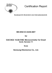
1
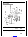
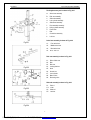
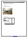
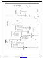
LAUNCH
Tyre Changer(TWC-502RMB)
Table of Contents
Safety Precautions………………….………….. 1
Main Structure……………………….…...…….. 2
Tools………………………………..…………….. 4
Installation………………………….……..……..4
Unpacking………………...….………….….….4
Installation……………………….……..…….….4
Transport………………………………….……6
Positioning……………….…….…………........6
Power and Air Connections……….………......6
Adjusting……………..…………………………6
Initial Operation ……..…….……………..…6
Clamping Unit of the aws………......................…....7
Drive system………………………………………..…7
Bead Breaker………………...……..….……... 8
Tilting column nit………..……..…..…….………8
Horizontal Arm and Hexagonal Column Clamping
Unit ………………….…….……….…….....9
Supplementary Arm ............………….….…9
Mount/demount Head………………….……10
Air Pressure Regulator, Gauge and Lubricator
Assembly………………………………..…...13
Parts List………..….……………..………..….…14
TWC-502RMB Circuit Diagram………..…….30
TWC-502RMB Pneumatic Diagram……….….33
i
PDF 文件使用 "pdfFactory Pro" 试用版本创建 www.fineprint.cn
LAUNCH
Tyre Changer(TWC-502RMB)
Safety Precautions
l
l
l
l
This manual is a necessary component of the
product. Please review carefully.
Keep the manual for later use when maintaining
the machine.
This machine can only be used for the designed
purpose. Never use it for any other purpose.
The manufacturer is not held responsible for any
damage incurred by improper use or use for the
purposes other than the intended one.
Before installing and adjusting the equipment, pay
attention to the following:
l
l
l
l
l
l
l
l
Read this manual and all other instructions for
the equipment thoroughly. Modification to any
components or parts, or use the machine for
other purpose without either obtaining the
permission from the producer, or observing the
requirement of the instructions may lead to direct
or indirect damage to the equipment.
The installation and adjusting personnel should
have a good understanding of electrical devices.
The equipment can only be operated by qualified
personnel with special training.
TWC-502RMB should be installed on the smooth
ground.
Keep the back panel 0.75M away from the wall
for good ventilation. Enough room should be left
on both sides of TWC-502RMB for convenient
operation.
Do not put TWC-502RMB in a place with high
temperature or moisture, or near the heating
system, water tap, air-humidifier or furnace.
Do not install TWC-502RMB near a window with
sunlight. Protect the unit with a curtain or shield
if necessary.
Go through the accessory list carefully before
installation. Should there be any questions
please contact your agent or Launch Tech Co.,
Ltd.
1
PDF 文件使用 "pdfFactory Pro" 试用版本创建 www.fineprint.cn
LAUNCH
Tyre Changer(TWC-502RMB)
Main Structure
Fig.01-1
A
Return spring
B
Swing arm
C
Hexagonal column
D
Mount/demount head
E
Clamping jaw
F
Turntable
G
Tilting
column
control pedal
H
I
Bead
breaker
control pedal
J
Turntable control pedal
K
L
N
Clamping cylinder
assembly
O
Hanger
P
Hexagonal column
locking handle
Bead
breaker
handle
Clamping
cylinder
control pedal
Tilting column
Q
Bead breaker arm
R
Ajusting pin
S
Bead breaker shoe
T
Tyre lever
U
Inflation pedal
V
Air Pressure Regulator, Gauge and Lubricator Assembly
W
Supplementary
assembly
2
PDF 文件使用 "pdfFactory Pro" 试用版本创建 www.fineprint.cn
arm
LAUNCH
Tyre Changer(TWC-502RMB)
The Supplementary arm is shown in Fig. 02-1.
abcdefghijk-
Swivel arm assembly
Disk arm assembly
Slide rod assembly
Lock cylinder assembly
Slide board assembly
Post assembly assembly
Lifting cylinder assembly
Press block
Disk
Control box assembly
Lock bar
Swivel arm assembly is shown in Fig. 02-2
Fig.02-1
a1. Fore swivel arm
a2. Middle swivel arm
a3. Back swivel arm
a4. Press slide set
Disk arm assembly is shown in Fig. 02-3
b1.
b2.
b3.
b4.
b5.
b6.
b7.
b8.
b9.
Fig.02-2
Roller of disk arm
Disk
Disk arm
Locking slide bar
Knob
Control box
Lock cylinder
Button valve
Reversing valve
Slide rod assembly is shown in Fig. 02-4
C1.
C 3.
C4.
C5.
Fig.02-3
Roller 1
Knob
Slide rod
Lock bar
Fig.02-4
3
PDF 文件使用 "pdfFactory Pro" 试用版本创建 www.fineprint.cn
LAUNCH
Tyre Changer(TWC-502RMB)
Tools
l
To ensure the correct installation and adjusting, please
get the following tools ready:
Two adjustable wrenches, one set of box spanners,
one pair of pliers, one set of screwdrivers, one digital
multi-meter (for voltage measurement).
l
l
Installation
Caution:
Special anti-rust oil is applied on the delicate parts
may attract dust. Clean it when necessary.
Unpacking
l
l
l
then knock the rotation shaft through holes with a
hammer. Use a wood block between hammer
and the shaft for protection when knocking. Fit
gaskets on both sides of the shaft before
fastening screws.
Remove the bolt and nut from the piston rod of
the tilting column cylinder. Get the bolt through
round holes on side boards of the tilting column
and the piston rod. Lock it with the locking nut.
Adjust four adjusting bolts to make the tilting
column on the right position (See Titling Unit)
Mount the front board to original position.
Remove packing following the instructions on the
package. Remove the packing materials and
check the machine for possible damage or loss
of accessories during transportation.
Keep the packing materials out of the reach of
children. Handle them in an appropriate way if
the packing materials cause pollution.
Remove the cabinet, tilting column t, horizontal
arm and accessory box fitted on the bottom plate
and put them in safety place.
Installation of Supplementary arm
device
l
Take out assembly of back swivel arm, post and
lifting cylinder, remove the hood(Fig.04). Then
take out disk assembly and relevant fastening
parts, apply lubricant on the fastening parts,
assemble them as Fig.05, mount back the hood
Installation
Installation of Titling column (Fig.03)
.
Fig.04
Fig.03
l
l
l
l
l
Place the cabinet at the right position.
Remove the front board and bottom rotation shaft
of tilting column with appropriate tools.
Apply lubricant on bottom rotation shaft and its
sleeve.
Lift up the tilting column . Run the PU hose
through inlet on the cabinet, and position the
tilting column onto the bottom seat.
Align the round holes on the bottom rotation
sleeve and the side boards of the bottom seat,
Fig.05
l
l
Remove the bolts (Fig.06) and washers on right
side plate of cabin, place the unit (Fig.05) on the
seat vertically,
Fit washers and fasten them with bolts. Get the
air compressing hose out from the bottom of post
4
PDF 文件使用 "pdfFactory Pro" 试用版本创建 www.fineprint.cn
LAUNCH
Tyre Changer(TWC-502RMB)
into cabinet through small hole on its right side
plate.
Fig.09
Air Connections
l
l
Fig.06
l
Take out Slide rod and relevant fastening parts,
brush lubricant on the parts, then assemble them
as in Fig.07.
l
After the post and supplementary arm fixed,
disassemble the sideboard of the cabinet
Find air compressing hoses out from the post ,
supplementary arm and airt-tank, insert them
into joint respectively. (Fig.09)
Shown in Fig10, get the two outlet airlines
of the air pressure regulator, gauge and
lubricator assembly through the round holes
of the cabinet rear compartment into the
cabinet inside, connect the airline1 with
tyre-inflating airline group (T-joint),connect
the airline2 with the cylinder airline group.
Fig.07
l
Take the bless block on tyre center, assemble it
on fore swivel arm as in Fig.08.
Fig.10
Installation of Air Tank
l
Fig.08
l
Fix the air tank on the cabinet with two sets of
bolts, nuts, spring washers and flat washer (Fig.
11).
Connect the rubber hose with the joint on the air
tank and fasten the screw of the hose hoop as
figure 11
5
PDF 文件使用 "pdfFactory Pro" 试用版本创建 www.fineprint.cn
LAUNCH
Tyre Changer(TWC-502RMB)
l
l
l
Fig.11
Positioning
The place to install the machine should be in
accordance with safety regulations:
l The machine should be installed in a place close
to the main power and compressed air source.
l Install the machine on smooth concrete ground
or other ground with hard flooring. 4 sets of
anchor bolts(M10×150) can be used to fasten the
machine onto the ground strongly to avoid
vibration and noise.
l Leave enough space around the machine for
proper operation and maintenance. The space
should be no less than 1M in front and on the two
sides of the machine and 0.5M behind it.
l If the machine has to be installed outdoors, a
protective shelter should be built.
l Free from flammable gases.
Fig.12
Fig.12
l
l
transportation.
Avoid excessive tilting in transportation.
Don’t drive the fork lift vehicle carrying the
equipment too fast.
Try to keep the machine at the lowest position
and make sure it won’t overturn in transportation
(pay attention to the position of the gravity
center).
connect the airline of the air-tank with one
branch of T-joint as Fig12..
Assemble the cabinet sideboard
Installation of Barometer
Install the barometer on one side of the tilting post
according to figure 13.
Note:
For the safety and proper operation, keep the
machine at least 0.75M away from any wall.
Power and Air Connections
l
l
Fig.13
please refer to the TWC-502RMB gas road map
to find out the specific connection method
l
Transport
l
Before installation, check if the power source and
the compressed air are in accordance with the
specifications on the nameplate. Any electrical
connection should be done by the specially
trained technician.
The power socket should be at a place within the
sight of the operator. The advisable height is
between 0.6 – 1.7M.
In case the main voltage is not stable, a voltage
stabilizer should be used between power source
and the machine.
The machine should be well grounded.
The tyre changer is not equipped with
overload protection. Please connect power
according to the circuit diagram included in the
User’s manual. Otherwise, the manufacturer
will not be responsible for any accidents.
It is advisable to transport the machine with fork lift
vehicle.
l Such movable parts: tray assembly, Bending arm
assembly, straight arm assembly, tilting column
and horizontal arm must be fastened to the
cabinet tightly with rope to avoid damages to
machine and injuries to people during
6
PDF 文件使用 "pdfFactory Pro" 试用版本创建 www.fineprint.cn
LAUNCH
Tyre Changer(TWC-502RMB)
Adjusting
Attention:
Make sure that the power supply, air sources
and the oil level in the oil cup are in accordance
with the requirements.
Initial Operation (Fig. 01)
Note:
The four pedals must be kept at the original
position.
l Press down the pedal (J) to turn the turntable
clockwise;
l Lift the pedal (J) to turn the turntable
counter-clockwise;
l Press down pedal (I) to move bead breaker;
release it to restore;
l Press down pedal (H) to move the jaws on the
turntable outward; pedal again to move them
inward;
l Press down pedal (G), the tilting column will tilt
backward. Pedal it again to restore the tilting
column upright.
l When the Rise/fall control leverr is lifted, the
supplementary arm device will go up.
l When the control lever is lowered down, the
supplementary arm device will go down.
l When the Inflation pedal U(Fig.01-1) is lightly
pressed, air will spout from the air hose
connected with the barometer. When the pedal is
pressed down to the lowest position, air will
quickly spout behind four jaws (the end of the
sliding mouse).
Fig. 14
Fig.15
l
Drive system
Clamping System of the Jaws(Fig.14)
l
l
l
l
The principle of the above motion can be
explained by the following: The three positions
on the cam control air reaching different holes on
the 5-way valve, so piston rod of clamping
cylinder is able to move back and forth and stop,
so do the clamping jaws.
The position of the jaw (Fig.15) on the turntable
is controlled by the movement of the piston rod,
which in turn is controlled by pedal H. There
are three levels for pedal H.
When pedal H on high, the piston rod will move
inward and pull the jaws moving inward until the
minimum. At this time the distance of two
opposite jaws is 10” for inner rim and 13” for
outer rim.
When pedal H on low, the piston rod will move
outward and pull the jaws moving outward until
the maximum. At this time the distance
between two opposite jaws is 20” for inner rim
and 23” for outer rim.
While the jaws in motion, press pedal H lightly to
keep it at the middle level, the jaws will stop in
response. Do this function flexible to get the
jaws anywhere between the maximum and
minimum for different wheels.
l
The gearing chain: The gearing chain in this
machine is made up of motor, pulley, worm
reducer, turntable and so on (Fig. 16).
l
The motor RPM is about 1400. The ratio of speed
is 200. The rotary direction is controlled by
pedal J . Press down the pedal to make the
turntable rotate clockwise. Release the pedal to
stop the turntable. Lift up the pedal J with foot,
Fig.16
7
PDF 文件使用 "pdfFactory Pro" 试用版本创建 www.fineprint.cn
LAUNCH
l
l
l
Tyre Changer(TWC-502RMB)
the motor and the turntable will both turn
counter-clockwise.
If contrary to above, change the phase wire of
the motor.
Connect the ground wire to ground.
In the operation, the turntable generally turns
clockwise, only when the operation is obstructed
occasionally, it needs to turn counter-clockwise.
Bead Breaker
l
l
l
The bead breaker is on the right side of the
cabinet. As the procedure requires, press down
pedal (I) (Fig.17)o start the bead breaker cylinder,
the piston rod will pull the bead breaker moving
towards the cabinet, with magnitude around
14075N. Release pedal (I), the bead breaker
will retract.
The bead breaker is able to swing within a
certain range. In case the range of swing is not
appropriate, adjust the nut (Fig.18)at the right
end of the piston rod.
The bead breaker arm is adjustable with two
ranges. According to the size of tyre, choose
range 1 or range 2. (Fig.19)
Fig.19
Tilting column Unit
l
l
l
The tilting column is under the control of tilting
cylinder in the cabinet, so that the column can tilt
backward in order to remove the tyre from the
turntable easily, and restore to upright position
(the working position).
The tilting cylinder is controlled by pedal G
When it is pressed, the tilting column tilts
backward; and when it is pressed again, the
column restore to the upright position (Fig.20)
If tilting speed is too fast or too slow, adjust the
throttles to change speed. If the speed is too fast,
fasten the screw on throttle mouth. If too slow,
loose the screw. The 5-way valve has two
throttles(Fig.21, of which “a” is for tilting
backward while “b” is for back to upright position.
Fig.17
Fig.20
Fig.18
Fig.21
l
There are two bolts on the base plate of the tilting
column to adjust the vertical position of the tilting
8
PDF 文件使用 "pdfFactory Pro" 试用版本创建 www.fineprint.cn
LAUNCH
Tyre Changer(TWC-502RMB)
column. Also, there are two bolts on the side
plates of the seat for limiting the horizontal
position of the tilting column. Before operation,
the two bolts on the base plate of the tilting
column should be on the same horizontal level to
ensure bearing the same weight. The side ends
of two bolts should be away 0.5—1mm from the
vertical plates of the tilting column.
Horizontal Arm and
Column Clamping Unit
l
with the sliding sleeve. Contrarily, when the
rise/fall control lever is pressed down, the
supplementary arm moves down. If it causes
flutter when supplementary arm moves up and
down, adjust the four locking screws on the side.
l
Group a of supplementary arm (fig.23). fore
swivel arm (a1) and middle swivel arm(a2) both
can turn freely around corresponding axis of back
swivel arm(a3). press block(h)can move on fore
swivel arm (a1) and fixed on back of fore swivel
arm (a1) for centering and pressing rim.
l
Group b of supplementary arm (fig24).roller of
disk arm(b1), with press block(h) and roller 1(c1)
is used to mount upper tyre bead under condition
without using mounting head. It also has other
functions. disk(b2) is used to demount tyre by
lifting tyre. switch between roller of disk arm (b1)
and disk (b2) by knob (b5). On control box(b6),
there is lock button(b8) and rise/fall control
lever(b9). disk arm is controlled by lock
button(b8). lock cylinder(b7) can lock by locking
slide bar(b4), so to control movement of disk arm.
Rise/fall control lever(B9) is to control movement
up and down of the supplementary arm.
l
Group c of supplementary arm as in
fig.25.Choose roller 1(c1) according to need and
fix it on fore part of slide rod(c4) by knob(c3).
Turn lock bar(c5) to lock slide rod (c4.)
Hexagonal
As shown in the figure 22 use (air valve) locking
button J on the handle (k) to control movement of
the clamping cylinder. When thumbed down the
button, the external shells of clamping cylinders
(b and g) are pushed out. Their external shells
touch locking boards (c and h). The tilting of the
boards will lock the horizontal arm and the
hexagonal column.
Fig.23
Fig.22
l
When the button is pressed out by index finger,
the clamping cylinder (b and g) will be drawn
back. The tilting boards (c and h) will relax to
loose the horizontal arm and the hexagonal
column. When it doesn’t work, nuts (e and i)
can be tightened or loosened for adjustment.
Supplementary Arm
l
Figure 02-1 shows structure of the
supplementary arm that consists of such three
main function units as roller, press block and disk.
The horizontal column unit, swivel arm unit, disk
unit and sliding sleeve integrate them together
and can move up and down along the sliding
column under control of rise/fall control lever on
the control box. When the rise/fall control lever is
lifted, the supplementary arm moves up along
Fig.24
9
PDF 文件使用 "pdfFactory Pro" 试用版本创建 www.fineprint.cn
LAUNCH
Tyre Changer(TWC-502RMB)
Tighten
screws
A1-A2
(Fig.28,32)
mount/demount head with roller; Fig.29, 33
mount / demount head with insert) to tilt the
mount / demount head and obtain the correct
position and then finger-tighten screw B.
l Unlock and raise the hexagonal column, then
lower it onto the rim and lock again.
l First tighten screws A1-A2-A3-A4 in torque of
50Nm and check by means of gauges that the
measurements remain the same.
l Lastly, tighten screw B to a torque of 50Nm and
carry out checks once again with the gauges.
Periodic checks
After use of the machine for half a year, do regular
check to ensure correct measurements as stated in
Checking. If they are incorrect proceed as follows:
l Check that the screws(A1-A2-A3-A4-B) are
tightened properly and repeat calibration as per
Calibration.
l If measurement 2 (roller, Fig.28) or measurement
1 (insert, Fig.29) are changed, the cause may be
that nut i(Fig.25) has loosened.
l Tighten or loosen nut i to increase or reduce
lifting range.
l If measurement 2 (Fig.30) has changed, this may
be due to loose nut e(Fig.22) or deformation of
locking plate c (Fig.22).in both case simply adjust
the nut, tighten or slacken to increase or reduce
movement range. Secure nuts with minimum
tightening torque 70Nm.
l
Fig.25
Mount / demount Head
Checking
Mount a 15 inch diameter aluminium alloy rim
(preferably new) onto the turntable.
l Lower the mount / demount head onto the rim
and lock.
l By means of the appropriate gauge kit, check
measurements as indicated in Fig.26 for
mount/demount head with roller) and
fig.27(mount / demount head with insert).
If the measurements do not correspond proceed as
follows:
Calibration
l Loosen all screws securing the mount / demount
head.
l Lower the mount / demount head onto the rim
and lock.
l Finger-tighten screws A3-A4(Fig.30 and Fig.31 in
order to turn the mount / demount head and
obtain the correct position.
l
Fig.26
10
PDF 文件使用 "pdfFactory Pro" 试用版本创建 www.fineprint.cn
LAUNCH
Tyre Changer(TWC-502RMB)
Fig.27
Fig.28
Fig.29
Fig.30
Fig.31
12
PDF 文件使用 "pdfFactory Pro" 试用版本创建 www.fineprint.cn
LAUNCH
Tyre Changer(TWC-502RMB)
Fig.32
Fig.33
Air Pressure Regulator, Gauge and
Lubricator Assembly
l
l
l
As shown in Fig.34, there is a button on the
regulator. When pulled up, the pressure can be
increased or decreased by turn it clockwise or
counter-clockwise. After adjusting the operation
pressure, press the button down to lock it.
The air cleaner works to filter the water and
impurity in the compressed air. When water
and impurities run beyond the red line, turn open
the draining valve to release them.
The lubricator is used to add a certain amount of
lubricant into gas for the moving parts in the
cylinder and regulator. Depress pedal H or J
3~5 times, a drop of lubricant will fall into the
cup in the regulator. If it does not happen, the
adjusting screw need to be adjusted.
Direction of the switch’s installation
Fig.34
Fig 35
13
PDF 文件使用 "pdfFactory Pro" 试用版本创建 www.fineprint.cn
LAUNCH
Tyre Changer(TWC-502RMB)
l
Connecting the power line to the switch (fig35)
Markers of two lines are 10 and12。They are no
sequence。
l
Installation of the switch
The switch’s position is shown as in fig36,
l
The switch parameter
f
Fig 36
14
PDF 文件使用 "pdfFactory Pro" 试用版本创建 www.fineprint.cn
LAUNCH
Tyre Changer(TWC-502RMB)
Parts List
This list is only for the reference of the maintenance personnel. The manufacturer will not be held responsible for any
use other than the designed purpose.
In case any damage occurs, please contact your dealer or LAUNCH with the corresponding codes in the list.
Note: The wearing parts are indicated by *.
15
PDF 文件使用 "pdfFactory Pro" 试用版本创建 www.fineprint.cn
LAUNCH
Tyre Changer(TWC-502RMB)
16
PDF 文件使用 "pdfFactory Pro" 试用版本创建 www.fineprint.cn
LAUNCH
Tyre Changer(TWC-502RMB)
17
PDF 文件使用 "pdfFactory Pro" 试用版本创建 www.fineprint.cn
LAUNCH
Tyre Changer(TWC-502RMB)
18
PDF 文件使用 "pdfFactory Pro" 试用版本创建 www.fineprint.cn
LAUNCH
Tyre Changer(TWC-502RMB)
19
PDF 文件使用 "pdfFactory Pro" 试用版本创建 www.fineprint.cn
LAUNCH
Tyre Changer(TWC-502RMB)
20
PDF 文件使用 "pdfFactory Pro" 试用版本创建 www.fineprint.cn
LAUNCH
Tyre Changer(TWC-502RMB)
21
PDF 文件使用 "pdfFactory Pro" 试用版本创建 www.fineprint.cn
LAUNCH
Tyre Changer(TWC-502RMB)
22
PDF 文件使用 "pdfFactory Pro" 试用版本创建 www.fineprint.cn
LAUNCH
Tyre Changer(TWC-502RMB)
Note:
The wearing parts are indicated by *.
No.
Eer code
Description
1
104130054
Pedal mat
2
103010326
Hexagon socket screw M6×12
3
201011874
Side plate
4
201011913
Cabinet
5
104010003
Cable clip
6
105010019
Cable
7
103202045
Hanger
8
104130246
Rubber pad A
9
103040063
Plain washer φ6
10
103010313
Hexagon socket screw M6×25
11
104130262
Rubber pad B
12
103020075
Hexagon bolt M8×25
13
103040026
Spring washer φ8
14
103030061
Nut M8
15
201012268
Hood
16
103160026
Safe valve
17
103020075
Hexagon bolt M10×25
18
103040064
Plain washer φ8
19
103040026
Spring washer φ8
20
103030061
Locking nut M8
21
103170007
Air tank
22
201020988
Quick deflation valve assembly
101
104130013
Working deck cushion cover
102
103020071
Hexagon Bolt M16×40
103
201010190
Working deck washer
104
201012013
Turntable
105
201011905
Square rotary body
106
Y103200250
Square rotary mat
107
103050018
Circlip for shaft φ65
108
201011907
Working deck taper sleeve
109
Y103220088
110
201010211
Clamping jaw
111
Y103220086
Sliding mouse
112
201011909
113
Y103220087
Slide carriage A
114
103202011
Connecting rod
115
103040112
Plain washer φ12
116
103202009
Connecting rod units
117
103040044
Spring washer φ12
118
103020164
Hexagon bolt M12×35
119
103040044
Spring washer φ12
Slide carriage B
Sliding plate
22
PDF 文件使用 "pdfFactory Pro" 试用版本创建 www.fineprint.cn
LAUNCH
Tyre Changer(TWC-502RMB)
120
103020062
Hexagon bolt M12×60
121
103040112
Plain washer φ12
122
103050002
Circlip for shaft φ12
123
104100258
Y Sealing ring 28×20×5
124
202010068
Guide sleeve
125
201011915
Clamping cylinder piston rod
126
103220082
Front cover of clamping cylinder
*127
104130081
O Sealing ring φ65×2.65
128
103040112
Plain washer φ12
129
104130053
Clamping cylinder piston
130
103040112
Plain washer φ12
*131
103040044
Spring washer light type φ12
132
103030061
Nut M8
133
103010327
Hexagon socket screw M8×25
134
103040049
Spring washer φ8
135
103040064
Plain washer φ8
136
103230054
Back cover of clamping cylinder
137
103220089
Clamping cylinder body
138
103100244
Nut locking
139
201020987
Clamping cylinder assembly
140
103100242
Nut 3-way pipe joint
141
104050033
Air compressing hose
201
Y103230037
202
103030106
Lock nut M16
203
103040117
Plain washer φ16
204
103230035
Bead breaker cylinder piston
205
104130055
High &low lip ring
206
104130061
O Sealing ring φ16×2.65
207
103040117
Plain washer φ16
208
201010172
Bead breaker cylinder piston rod
209
104130060
O Sealing ring φ180×3.55
210
103230168
Bead breaker cylinder cover
211
104130079
O Sealing ring φ19×2.65
212
202010068
Guide sleeve
213
201010179
Set screw
214
103040112
Plain washer φ12
215
201010179
Set screw
216
103100246
Nut locking
217
201021001
Bead breaker cylinder assembly
218
104130052
Bead breaker cylinder pressure mat
219
202010060
Bead breaker buffer
220
103201998
Guide Roller
221
201012021
Bead breaker shoe arm
222
103030106
Lock nut M16
L joint
Bead breaker cylinder body
L joint
23
PDF 文件使用 "pdfFactory Pro" 试用版本创建 www.fineprint.cn
LAUNCH
Tyre Changer(TWC-502RMB)
223
103110013
Tension spring
224
201011649
Shaft arm pin
225
103040097
Plain washer φ22
226
103050004
Circlip for shaft φ22
227
103030089
Nut M12
228
103040112
Plain washer φ12
229
201012489
Extention plate weldment
230
X201010233
231
201010185
Bead breaker shoe
232
201011897
Ajusting pin
233
103010282
Hexagon socket screw M12×85
234
103040112
Plain washer φ12
235
103030089
Lock nut M12
236
104130075
Bead breaker shoe handle cowl
301
103010327
Hexagon socket screw M8×25
302
104010272
Cap
303
103110079
Return spring
304
201011889
Locking board
305
201011891
Horizontal arm
306
201011494
Hexagonal column
307
104070027
Cushion mat
308
104070052
Lock handle units
309
202020029
Lock handle assembly
310
202010053
Cushion cowl
311
202010058
Locking cylinder assembly
312
104050032
Air compressing hose φ6
313
104020066
Protective hood
314
103010401
Hexagon socket set screws with flat point M12×12
315
201020141
Metal Mount/demount head
316
103040077
Mount/demount head mat
317
103020057
Hexagon socket set screws with flat point M10×25
318
103060014
Pin of Mount/demount head roller
319
201010121
Mount/demount head roller
320
104070010
Mount/demount head mat
321
104070009
Mount/demount head slide block
322
201011886
Tilting column
323
201011882
Ajustable block
324
103201989
Ajustable roller
325
201011883
Back locking board
326
201010315
Hook
327
#N/A
328
104080004
Lock cylinder body
329
104130085
Sealing mat
330
Y103220077
Universal joint
Locking cylinder assembly
Lock cylinder cover
24
PDF 文件使用 "pdfFactory Pro" 试用版本创建 www.fineprint.cn
LAUNCH
Tyre Changer(TWC-502RMB)
331
103100244
L Elbow coupling
332
201011565
Column bottom rotating shaft
333
201010352
Axle pin mat
334
103202053
Cylinder shaft
335
104070028
Buffer block
336
104070066
Cushion mat 2
337
104070028
Buffer block
338
104130258
Y Sealing ring 28×20×5
339
103230146
Front cover of tilting column cylinder body
340
104130296
O Sealing ring φ75×2.65
341
201011641
Cylinder piston lever
342
104130170
Buffer block
344
201011642
Cushion base
345
201011638
Tilting column cylinder piston
346
103230140
Tilting column cylinder body
347
201011640
Cylinder stay stud
348
103230147
Back cover of tilting column cylinder body
349
103010398
Hexagon bolt M16*160
350
202010068
Casing
351
103100211
L Elbow coupling
352
103030066
Lock nut M12
353
104130297
O Sealing ring φ11.8*1.8,GB/T3452.1-1992
354
104130247
Y Sealing ring 80×65×9.5
355
201020847
Tilting column cylinder assembly
356
103100202
Iflating airline spigot
357
201020141
Metal Mount/demount head assembly
401
103030102
Lock nut M14
402
103040097
Plain washer φ14
403
103080002
Key A6×20
404
103230034
Pulley of speed reducer
405
104130083
FB Sealing ring 20×35×7
406
104130080
O Sealing ring φ34.5×3.55
407
103060022
Tapered roller bearing
408
103200291
Worm
409
104990075
Sealing cover units of reduction gear box
410
103230033
Upper cover of worm case
411
201012010
Worm bearing
412
103070007
Angular contact bearing
413
103202048
Casing of reduction gear box
414
103200789
Worm wheel
415
103070007
Angular contact bearing
416
103230052
Lower cover of worm case
417
103080001
Key A14×40
418
103020057
Hexagon bolt M10×25
25
PDF 文件使用 "pdfFactory Pro" 试用版本创建 www.fineprint.cn
LAUNCH
Tyre Changer(TWC-502RMB)
419
103040100
Spring washer φ10
420
103030063
Thin nut M10
421
201020981
Gear reducer assembly
422
103020075
Hexagon bolt M8×25
423
103040026
Spring washer φ8
424
103040064
Motor plain cushion
425
104130255
V Vee belt A28′
426
103220048
Motor pulley
427
103080002
Plain key C5×30
428
202010009
Motor cushion mat
429
201012400
Motor support
430
102990095
Motor
~110V/60Hz 1.1kw
430A
Motor
~230V/50Hz 1.1kw
430B
Motor
~230V/60Hz 1.1kw
Motor
~220V/50Hz 1.1kw
Motor
~220V/60Hz 1.1kw
Motor
~110V/60Hz 1.1kw
Motor
~110V/50Hz 1.1kw
430C
102990104
430D
430E
102990103
430F
431
104050033
Air compressing hose
432
103100248
Male connector
433
104050007
Nozzle of rotary valve
434
103100248
Male connector
435
202010011
Pneumatic spool unit
436
104130062
O Sealing ring φ60×2.65
437
202010010
Pneumatic valve pocket
438
202020008
Rotary pneumatic valve assembly
501
104050033
Air compressing hose
502
103100247
Male branch tee
503
103100003
Muffler
504
104010274
Pentagamma valve units
505
104130074
O Sealing ring φ11.8×4
506
104010271
Pentagamma casing
507
103010120
Cross socket set screws with flat point M4×10
508
104010273
Five-way valve cover
509
201010232
Cam hood
510
104120025
Cam body
511
103110025
Cam spring sheet
512
202010077
Transfer shift bar
513
104020044
Steering switch cover
514
102100101
Motor power switch
515
103110033
Pedal release spring
516
X201010226
Reed type support
517
201010329
Pedal support units
518
103110032
Reed type
26
PDF 文件使用 "pdfFactory Pro" 试用版本创建 www.fineprint.cn
LAUNCH
Tyre Changer(TWC-502RMB)
519
103040112
Plain washer φ12
520
201010262
Transfer shift connecting rod
521
X201010326
Pedal casing
522
Y103220073
Cam connecting rod
523
103030098
Locking nut M8
524
103050002
Circlip for shaft φ12
525
103040112
Plain washer φ12
526
103200710
Pedal bearing
527
Y103220072
Transfer shift pedal
528
Y103220075
Pentagamma valve pedal
529
201020835
Pedal assembly
530
202020007
Pentagamma valve assembly
531
103100043
Adjustable silencer
532
103100248
Nut locking
536
201010296
Plate 2
537
X201010868
Plate 1
538
#N/A
539
103160025
Two position three-way valve
540
103100121
Male connector
541
201020181
Quick deflation valve core
543
201021207
Pedal valve assembly
601
201011975
Fore swivel arm
602
201012006
Middle swivel arm
603
201011951
Back swivel arm
604
201011998
Slide sleeve
605
103201987
Press bar
606
104070063
Press block
610
202010065
Roller 1
611
103201993
Axis of roller
612
201011946
Slide rod
613
103030097
Roundness nut handle, M8
614
202010065
Roller of disk arm
615
201011995
Disk seat
616
104070061
Disk
617
201011990
Axis of disk
618
103201963
Disk arm
619
103202015
Locking pin
620
103202014
Locking connector
621
103050001
Circlip
622
103030149
Nut
623
201011977
Locking
624
201011952
Slide board hood
625
103202012
Pin of back swivel arm
626
201011953
Slide board weldment
L joint
JSM-Z6-G1/8
#N/A
slide bar
27
PDF 文件使用 "pdfFactory Pro" 试用版本创建 www.fineprint.cn
LAUNCH
Tyre Changer(TWC-502RMB)
627
103030068
Nut M20
628
104010019
Lock bar
629
103010568
Hexagon socket screw
630
103040135
Plain washer
631
103201985
Sleeve
632
104080004
Lock cylinder body
633
202010066
Lock cylinder piston
634
201011976
Up locking block
635
201011980
Lock cylinder piston lever
636
103110084
Lock spring
637
201011976
Down locking block
638
201011983
Lock support
639
103030106
Nut
640
201010772
Right slider
641
201010771
Regulating chip of slider
642
201010752
Sliding guide
643
201010773
Left slider
644
201011966
Post support weldment
645
201011966
Cover of post
646
201011967
Post assembly
647
201012011
Carriage weldment
648
201010754
Pin on bottom of cylinder
649
103050001
Spring washer15
650
103202013
Pin on cylinder top
651
103050002
Spring washer 12
652
x201020818
Lifting cylinder assembly
653
201012057
Cylinder hood right carriage
654
201011970
Cylinder hood left carriage
655
201011969
Cylinder hood assembly
656
104990080
Cover of cylinder hood
657
104010506
Control box
658
103160090
Button valve
659
103160052
Reversing valve
660
103100282
Quick L end joint φ6*M5
661
103100043
Adjustable silencer
663
103030097
Roundness nut handle, M8
664
103110083
Set pin spring
665
201011984
Set pin of disk arm
666
103010567
Hexagon socket set screws with column end
667
201020995
Supplementary arm assembly
668
103201964
Adjusting base
701
306070016
Tyre lever
702
#N/A
703
201010225
Plastic Mount/demount head and Mount/demount head base assembly
Mount/demount head base
28
PDF 文件使用 "pdfFactory Pro" 试用版本创建 www.fineprint.cn
LAUNCH
Tyre Changer(TWC-502RMB)
704
103010371
Hexagon socket set screws with flat point M8×20
705
Y104990077
706
103040096
Plain washer φ10
707
103020058
Hexagon bolt M10×50
708
103010327
Hexagon socket screw M8×25
709
103040064
Plain washer φ8
710
103160011
Air pressure regulator
711
103100122
L Elbows
712
103990019
Air Pressure Regulator, Gauge and Lubricator Assembly
713
103990047
variometer φ40
714
201020857
Box variometer assembly
715
201020181
Quick deflation valve core
716
103160032
variometer φ75
Plastic Mount/demount head
29
PDF 文件使用 "pdfFactory Pro" 试用版本创建 www.fineprint.cn
AC110V
60Hz
30
PDF 文件使用 "pdfFactory Pro" 试用版本创建 www.fineprint.cn
4
2
6
5
8
7
U1 U2 U3 U4 V1 Z1
3
1
11
1O 12
9
2.5mm
current : 19A
2
industrial power plug
PLUG
Remarks:if the motor movement is contrary to the right
turning,change the phase wire(Z1 and V1).
switch
SW1
EN60309
EN60947-3
32A
Mennekes plug 274#
32A/2P+E/230V/IP44
Remarks
EN60309
EN60947-2
Remarks
Model
SOCKET
Name
Mennekes socket 536#
32A/2P+E/230V/IP44
industrial power
socket
No.
rated current 40A
Model
air-break switch
Name
QF1
No.
industrial power plug
maximum current : 32A
QF1
protective current :
40A
This protective circuit should be
fulfiled by the customer
LAUNCH
Tyre Changer(TWC-502RMB)
TWC-502RMB Circuit Diagram
AC230V
60Hz
31
PDF 文件使用 "pdfFactory Pro" 试用版本创建 www.fineprint.cn
4
2
6
5
8
7
U1 U2 U3 U4 V1 Z1
3
1
11
Name
switch
industrial power plug
No.
SW1
PLUG
industrial power plug
maximum current: 32A
EN60309
SOCKET
Mennekes plug 274#
32A/2P+E/230V/IP44
16A
Model
Mennekes socket 536#
32A/2P+E/230V/IP44
EN60947-2
EN60309
EN60947-3
Remarks
Remarks
industrial power
socket
Model
air-break switch rated current 20A
Name
QF1
No.
Remarks :if the motor movement is contrary to the right
turning,change the phase wire(Z1 and V1).
1O 12
9
1.5mm2
current:9.1A
QF1
protective current :
20A
This protective ciruit should be
fulfiled by the customer
LAUNCH
Tyre Changer(TWC-502RMB)
AC220V
50HZ
32
PDF 文件使用 "pdfFactory Pro" 试用版本创建 www.fineprint.cn
4
2
U1
3
1
Z1
6
5
Z2
U2
8
7
11
Name
switch
industrial power plug
No.
SW1
PLUG
industrial power plug
maximum current: 32A
Mennekes plug 274#
32A/2P+E/230V/IP44
16A
Model
EN60309
EN60309
EN60947-3
Remarks
Mennekes socket 536#
32A/2P+E/230V/IP44
industrial power
socket
SOCKET
EN60947-2
rated current 20A
air-break switch
QF1
Remarks
Model
Name
No.
Remarks: if the motor movement is contrary to the right
turning,change the phase wire(Z1 and Z2).
1O 12
9
1.5mm 2
current:9.1A
QF1
protective current :
20A
This protective ciruit should be
fulfiled by the customer
LAUNCH
Tyre Changer(TWC-502RMB)
LAUNCH
Tyre Changer(TWC-502RMB)
TWC-502RMB Pneumatic Diagram
33
PDF 文件使用 "pdfFactory Pro" 试用版本创建 www.fineprint.cn