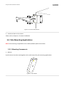
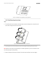
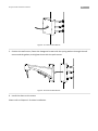
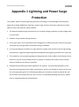
1
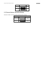
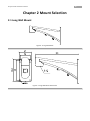
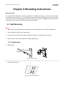
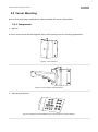
IR Speed Dome Installation Manual V2.0.1 IR Speed Dome Installation Manual 0 Hikvision® IR Speed Dome User’s Manual This manual is furnished under license and may be used or copied only in accordance with the terms of such license. The content of this manual is furnished for informational use only, is subject to change without notice, and should not be construed as a commitment by Hikvision Digital Technology Co., Ltd. (Hikvision). Hikvision assumes no responsibility or liability for any errors or inaccuracies that may appear in the book. Except as permitted by such license, no part of this publication may be reproduced, stored in a retrieval system, or transmitted, in any form or by any means, electronic, mechanical, recording, or otherwise, without the prior written permission of Hikvision. HIKVISION MAKES NO WARRANTIES, EXPRESS OR IMPLIED, INCLUDING WITHOUT LIMITATION THE IMPLIED WARRANTIES OF MERCHANTABILITY AND FITNESS FOR A PARTICULAR PURPOSE, REGARDING THE HIKVISION SOFTWARE. HIKVISION DOES NOT WARRANT, GUARANTEE, OR MAKE ANY REPRESENTATIONS REGARDING THE USE OR THE RESULTS OF THE USE OF THE HIKVISION SOFTWARE IN TERMS OF ITS CORRECTNESS, ACCURACY, RELIABILITY, CURRENTNESS, OR OTHERWISE. THE ENTIRE RISK AS TO THE RESULTS AND PERFORMANCE OF THE HIKVISION SOFTWARE IS ASSUMED BY YOU. THE EXCLUSION OF IMPLIED WARRANTIES IS NOT PERMITTED BY SOME STATES. THE ABOVE EXCLUSION MAY NOT APPLY TO YOU. IN NO EVENT WILL HIKVISION, ITS DIRECTORS, OFFICERS, EMPLOYEES, OR AGENTS BE LIABLE TO YOU FOR ANY CONSEQUENTIAL, INCIDENTAL, OR INDIRECT DAMAGES (INCLUDING DAMAGES FOR LOSS OF BUSINESS PROFITS, BUSINESS INTERRUPTION, LOSS OF BUSINESS INFORMATION, AND THE LIKE) ARISING OUT OF THE USE OR INABILITY TO USE THE HIKVISION SOFTWARE EVEN IF HIKVISION HAS BEEN ADVISED OF THE POSSIBILITY OF SUCH DAMAGES. BECAUSE SOME STATES DO NOT ALLOW THE EXCLUSION OR LIMITATION OF LIABILITY FOR CONSEQUENTIAL OR INCIDENTAL DAMAGES, THE ABOVE LIMITATIONS MAY NOT APPLY TO YOU. IR Speed Dome Installation Manual 1 Regulatory Information FCC Information FCC compliance: This equipment has been tested and found to comply with the limits for a digital device, pursuant to part 15 of the FCC Rules. These limits are designed to provide reasonable protection against harmful interference when the equipment is operated in a commercial environment. This equipment generates, uses, and can radiate radio frequency energy and, if not installed and used in accordance with the instruction manual, may cause harmful interference to radio communications. Operation of this equipment in a residential area is likely to cause harmful interference in which case the user will be required to correct the interference at his own expense. FCC Conditions This device complies with part 15 of the FCC Rules. Operation is subject to the following two conditions: 1. This device may not cause harmful interference. 2. This device must accept any interference received, including interference that may cause undesired operation. EU Conformity Statement This product and - if applicable - the supplied accessories too are marked with "CE" and comply therefore with the applicable harmonized European standards listed under the Low Voltage Directive 2006/95/EC, the EMC Directive 2004/108/EC. 2002/96/EC (WEEE directive): Products marked with this symbol cannot be disposed of as unsorted municipal waste in the European Union. For proper recycling, return this product to your local supplier upon the purchase of equivalent new equipment, or dispose of it at designated collection points. For more information see: www.recyclethis.info. 2006/66/EC (battery directive): This product contains a battery that cannot be disposed of as unsorted municipal waste in the European Union. See the product documentation for specific battery information. The battery is marked with this symbol, which may include lettering to indicate cadmium (Cd), lead (Pb), or mercury (Hg). For proper recycling, return the battery to your supplier or to a designated collection point. For more information see: www.recyclethis.info. Description on Laser Specification The optical disc drive such as DVD Super Multi (Double Layer) Drive 22X that is used in this computer is equipped with laser. The classification label with the following sentence is affixed to the surface of the drive. CLASS 1 LASER PRODUCT TO IEC60825-1 LASER KLASSE 1 The drive with the above label is certified by the manufacturer that the drive complies with the requirement for laser product on the date of manufacturing pursuant to article 21 of Code of Federal Regulations by the United States of America, Department of Health & Human Services, Food and Drug Administration. In other countries, the drive is certified to comply with the requirement pursuant to IEC 60825-1 and EN 60825-1 on class 1 laser product. This computer is equipped with the optical disc drive in the following list according to the model. IR Speed Dome Installation Manual 1 Safety Warnings and Cautions Please pay attention to the following warnings and cautions: Hazardous Voltage may be present: Special measures and precautions must be taken when using this device. Some potentials (voltages) on the device may present a hazard to the user. This device should only be used by employees from our company with knowledge and training in working with these types of devices that contain live circuits. Power Supply Hazardous Voltage: AC mains voltages are present within the power supply assembly. This device must be connected to a UL approved, completely enclosed power supply, of the proper rated voltage and current. No user serviceable parts inside the power supply. System Grounding (Earthing): To avoid shock, ensure that all AC wiring is not exposed and that the earth grounding is maintained. Ensure that any equipment to which this device will be attached is also connected to properly wired grounded receptacles and are approved medical devices. Power Connect and Disconnect: The AC power supply cord is the main disconnect device to mains (AC power).The socket outlet shall be installed near the equipment and shall be readily accessible. Installation and Maintenance: Do not connect/disconnect any cables to or perform installation/maintenance on this device during an electrical storm. Power Cord Requirements: The connector that plugs into the wall outlet must be a grounding-type male plug designed for use IR Speed Dome Installation Manual 2 in your region. It must have certification marks showing certification by an agency in your region. The connector that plugs into the AC receptacle on the power supply must be an IEC 320, sheet C13, female connector. See the following website for more information http://kropla.com/electric2.htm. Lithium Battery: This device contains a Lithium Battery. There is a risk of explosion if the battery is replaced by an incorrect type. Dispose of used batteries according to the vendor’s instructions and in accordance with local environmental regulations. Perchlorate Material: Special handling may apply. See www.dtsc.ca.gov/hazardouswaste/perchlorate. This notice is required by California Code of Regulations, Title 22, Division 4.5, Chapter 33: Best Management Practices for Perchlorate Materials. This device includes a battery which contains perchlorate material. Taiwan battery recycling: Please recycle batteries. Thermal and Mechanical Injury: Some components such as heat sinks, power regulators, and processors may be hot; care should be taken to avoid contact with these components. Electro Magnetic Interference: This equipment has not been tested for compliance with emissions limits of FCC and similar international regulations. This device is not, and may not be, offered for sale or lease, or sold, or leased until authorization from the United States FCC or its equivalent in other countries has been obtained. Use of this equipment in a residential location is prohibited. This equipment generates, uses and can radiate radio frequency energy which may result in harmful interference to radio communications. If this equipment does cause harmful interference to radio or television reception, which can be determined by turning the equipment on and off, the user is required to take measures to eliminate the interference or discontinue the use of this equipment. Lead Content: Please recycle this device in a responsible manner. Refer to local environmental regulations for proper recycling; do not dispose of device in unsorted municipal waste. IR Speed Dome Installation Manual 3 Preventive and Cautionary Tips Before connecting and operating this product, please be advised of the following tips: • All the operations should strictly comply with the local electrical safety regulations, fire prevention regulations and other related regulations. • Ensure unit is properly secured. Major shocks or jolts to the unit as a result of dropping it may cause damage to the sensitive electronics within the unit. • Power down the unit before connecting and disconnecting accessories and peripherals. • Make sure that the endure ability of ceilings or walls is 4 times as the weight of speed dome and its accessories. 1. Preparation of cables 2. Choose the video cable according to the transmission length. The video should meet the least demands as: 1. 75Ω resistance 2. 100% copper core conducting wire. 3. 95% weaving copper shield. RS485 communication cable, please refer to Appendix 2 24V AC power cable, please refer to Appendix 3 Please keep all wrappers Please keep all wrappers after unpack them for future use. In case of any failure occurred, please return the speed dome to the factory with the original wrapper. Note: Transportation without the original wrapper may result in damage on the speed dome and cost additional charge. 4 IR Speed Dome Installation Manual Table of Contents Chapter 1 Installation and Settings .............................................................................................................................. 5 1.1 Installation ..................................................................................................................................................... 5 1.2 Cabling........................................................................................................................................................... 8 1.2.1 Cable Standards .................................................................................................................................. 8 1.2.2 Cabling Instructions ............................................................................................................................ 9 1.2.3 Alarm Input /Output .......................................................................................................................... 12 1.3 DIP Switch Settings ..................................................................................................................................... 12 1.3.1 Address Settings................................................................................................................................ 13 1.3.2 Baud Rate Settings ............................................................................................................................ 16 1.3.3 Protocol Settings ............................................................................................................................... 16 1.3.4 Communication Type Settings .......................................................................................................... 16 1.3.5 Terminal Resistor Connection Settings ............................................................................................. 17 Chapter 2 Mount Selection ........................................................................................................................................ 18 2.1 Long Wall Mount ......................................................................................................................................... 18 2.2 Short Wall Mount......................................................................................................................................... 19 2.3 Corner Mount............................................................................................................................................... 20 2.4 Pole Mount................................................................................................................................................... 20 Chapter 3 Mounting Instructions............................................................................................................................... 21 3.1 Wall Mounting ....................................................................................................................................... 21 3.1.1 Components ............................................................................................................................... 21 3.1.2 Mounting with a Long Mount .................................................................................................... 22 3.1.3 Mounting with a Power Supply Box .......................................................................................... 23 3.2 Corner Mounting ................................................................................................................................... 24 3.2.1 Components ............................................................................................................................... 24 3.2.2 Corner Mounting Instructions .................................................................................................... 25 3.3 Pole Mounting Applications .................................................................................................................. 26 3.3.1 Mounting Components............................................................................................................... 26 3.3.2 Pole Mounting Instructions ........................................................................................................ 28 Appendix 1 Lightning and Power Surge Protection ................................................................................................... 30 Appendix 2 RS485 Bus Connection ............................................................................................................................ 32 Appendix 3 Wire Gauge Standards ............................................................................................................................ 35 5 IR Speed Dome Installation Manual Chapter 1 Installation and Settings The following installation instructions are applicable to Hikvision IR speed domes, network IR speed domes and network high-definition IR speed domes. Wall mounting is chosen as an example in this chapter. Please refer to Chapter 3 for different types of mountings. Note: Before installation, please make sure that the device in the package is in good condition and all the assembly parts are complete. Before you start: 1. For cement walls, expansion screws are needed for dome mounting. For wooden walls, you need to mount the base with self-tapping screws. Please make sure that the wall is sturdy enough to withstand more than 3 times of the weight of the dome and the bracket. If not, the dome may fall and cause serious damage. 2. Please keep the wrappers after unpack the product. In case of any failure occurred, please return the speed dome to the dealer with the original wrapper. Note: Transportation without the original wrapper may result in damage to the speed dome and extra cost. 1.1 Installation Steps: 1. Position the mount to the wall and fasten the lock screws to secure it. Figure1. 1 Wall Mount 2. Screw the fast-mounting adapter to the wall mount and tighten it. Fasten the set screw to reinforce as shown in Figure 1.2 6 IR Speed Dome Installation Manual Figure1. 2 Fasten the fast-mounting Adapter 3. Loosen both of the lock screws on the fast-mounting adapter, screw the top cover to the adapter and fasten the lock screws with the L-shaped wrench. Figure1. 3 Install the Top Cover Figure1. 4 Fasten the Lock Screws 4. Tear off the protective sticker from the dome as shown in figure 1.2.5. 7 IR Speed Dome Installation Manual Protective Sticker Network High-definition IR Speed Dome (Network) IR Speed Dome Figure1. 5 Tear off the Protective Stickers 5. Install the sealing loop or waterproofing and tie the safety lanyard to the dome. Network High-definition IR Speed Dome (network) IR Speed Dome Figure1. 6 Install the Sealing Loop Network High-definition IR Speed Dome (Network) IR Speed Dome Figure1. 7 Tie the safety lanyard 8 IR Speed Dome Installation Manual 6. Hang the hanging hook on the dome bottom to the top cover. Pass the integrated cable through the mount and the top cover, and connect it into the corresponding slots on the bottom circuit board (For cabling, please refer to section 1.2 to see more details). Network High-definition IR Speed Dome (network) IR Speed Dome Figure1. 8 Hang the Dome to the Top Cover 7. Fasten the set screws to reinforce the mounting Network High-definition IR Speed Dome Figure1. 9 Fix the IR Speed Dome 1.2 Cabling Note: Please turn off the power before cabling. 1.2.1 Cable Standards 1. Video Cable (Network) IR Speed Dome 9 IR Speed Dome Installation Manual Please choose the video cables according to the transmission length. It should meet following requirements: 75Ω resistance; 100% copper core conducting wire; 95% weaving copper shield. 2. For RS485 communication cables, please refer to Appendix 2 3. For 24V AC power cables, please refer to Appendix 3 For AC power supply, the maximum transmission distance (L(m)) is limited by the bare cable’s cross-sectional area(S (mm²)) of the dome. For IR speed dome, L (m) = 50 * S; while for network IR speed domes, L (m) =40 * S. For example, if the cross-sectional area of bare cable is 1mm ², the transmission distance of IR speed dome and network IR speed dome should not exceed 50m and 40m respectively. 1.2.2 Cabling Instructions 4. Internal cables For analog cameras, all the internal cables have been connected to corresponding interfaces; for network cameras, network cable, power cable and video output cable have been connected. 5. External cables To connect external cables to corresponding equipment, please refer to the cable labels as shown in Figure 1.10 and 1.11. Figure1. 10 Analog Speed Dome Integrated Cables 10 IR Speed Dome Installation Manual Figure1. 11 Network Speed Dome Integrated Cables Take alarm input/output cabling for IR speed dome as an example: Steps: 6. Open the head cover of the dome and find the alarm in/out terminals on the bottom circuit board as shown in Figure1.12. 7. Find the alarm input/output cables. You can distinguish the cables by color and labels (Eg. Audio output cable in orange with label “AUDIO_OUT”, please refer to Figure 1.10 and Figure 1.11 for more information) 8. Remove the protective covering from the cable plug. 9. Connect the cable to the corresponding slot on the circuit board and secure the cable with lock screws. 10. Connect the cables to the external alarm devices (See Figure 1.10 and Figure 1.11). 11 IR Speed Dome Installation Manual Figure1. 12 Bottom Circuit Board of IR Speed Dome Figure1. 13 Bottom Circuit Board of Network IR Speed Dome 12 IR Speed Dome Installation Manual Figure1. 14 Bottom Circuit Board of Network High-definition IR Speed Dome) 1.2.3 Alarm Input /Output Both the IR speed dome and network IR speed dome models support up to 7 alarm inputs (0~12VDC), 2 alarm outputs and relay output (no voltage). GND OUT DC Load Dome Relay Output OUT(n) + DC - OUT(n) 12VDC 30mA Dome JQC-3FG Relay (10 A 250VAC) OUT(n) ~220V AC L N Relay Output OUT(n) Diagram (left) Diagram(right) Figure1. 15 Alarm Connections To connect external alarm devices, external power supply is required as below: 1. For DC power supply (refer to the left diagram of Figure 1.16), input voltage should be within 12VDC, 30mA. 2. For AC power supply (right diagram), an external relay is required to avoid any potential danger. 1.3 DIP Switch Settings There are two DIP switches SW1 and SW2 for address, baud rate and protocol settings. 13 IR Speed Dome Installation Manual Note: 1. 485 serial port parameters of network high-definition IR speed dome should be configured in OSD menu. You can login to client software or open IE browser and navigate to “Remote Settings” to configure. 2. Default settings: Address code: 0;baud rate: 2400; 120Ω matched resistor: OFF Before you start: Please remove the grounding screw from the circuit board if electromagnetic interferences exist. 1 2 1. Address DIP Switch 2. Protocol DIP Switch 3. Address and Protocol Settings 4. Grounding screw 4 3 Figure1. 16 Bottom Board of IR speed dome 1.3.1 Address Settings There are 8 positions of switch SW1 for dome address settings. Set the position to “OFF” for value “0” and “ON” for value “1”. 14 IR Speed Dome Installation Manual Dome Address SW1 Settings 1 ON 0 7 8 6 7 8 OFF OFF OFF OFF OFF OFF OFF OFF 2 3 4 5 6 7 8 ON OFF OFF OFF OFF OFF OFF OFF 2 3 4 5 6 7 8 SW1 1 6 5 ON 255 5 4 SW1 1 4 3 ON 1 3 2 SW1 1 2 ON ON ON ON ON ON ON Table 1.1 Address Settings For addresses 0-71, please refer to Table 1.2: Dome DIP Switch SW1-Address Settings Address 1 2 3 4 5 6 7 8 0 OFF OFF OFF OFF OFF OFF OFF OFF 1 ON OFF OFF OFF OFF OFF OFF OFF 2 OFF ON OFF OFF OFF OFF OFF OFF 3 ON ON OFF OFF OFF OFF OFF OFF 4 OFF OFF ON OFF OFF OFF OFF OFF 5 ON OFF ON OFF OFF OFF OFF OFF 6 OFF ON ON OFF OFF OFF OFF OFF 7 ON ON ON OFF OFF OFF OFF OFF 8 OFF OFF OFF ON OFF OFF OFF OFF 9 ON OFF OFF ON OFF OFF OFF OFF 10 OFF ON OFF ON OFF OFF OFF OFF 11 ON ON OFF ON OFF OFF OFF OFF 12 OFF OFF ON ON OFF OFF OFF OFF 13 ON OFF ON ON OFF OFF OFF OFF 14 OFF ON ON ON OFF OFF OFF OFF 15 ON ON ON ON OFF OFF OFF OFF 16 OFF OFF OFF OFF ON OFF OFF OFF 17 ON OFF OFF OFF ON OFF OFF OFF 18 OFF ON OFF OFF ON OFF OFF OFF 19 ON ON OFF OFF ON OFF OFF OFF 20 OFF OFF ON OFF ON OFF OFF OFF 21 ON OFF ON OFF ON OFF OFF OFF 22 OFF ON ON OFF ON OFF OFF OFF 23 ON ON ON OFF ON OFF OFF OFF 24 OFF OFF OFF ON ON OFF OFF OFF 25 ON OFF OFF ON ON OFF OFF OFF 26 OFF ON OFF ON ON OFF OFF OFF 27 ON ON OFF ON ON OFF OFF OFF 28 OFF OFF ON ON ON OFF OFF OFF 29 ON OFF ON ON ON OFF OFF OFF 30 OFF ON ON ON ON OFF OFF OFF 31 ON ON ON ON ON OFF OFF OFF 32 OFF OFF OFF OFF OFF ON OFF OFF 33 ON OFF OFF OFF OFF ON OFF OFF 34 OFF ON OFF OFF OFF ON OFF OFF ON 15 IR Speed Dome Installation Manual 35 ON ON OFF OFF OFF ON OFF OFF 36 OFF OFF ON OFF OFF ON OFF OFF 37 ON OFF ON OFF OFF ON OFF OFF 38 OFF ON ON OFF OFF ON OFF OFF 39 ON ON ON OFF OFF ON OFF OFF 40 OFF OFF OFF ON OFF ON OFF OFF 41 ON OFF OFF ON OFF ON OFF OFF 42 OFF ON OFF ON OFF ON OFF OFF 43 ON ON OFF ON OFF ON OFF OFF 44 OFF OFF ON ON OFF ON OFF OFF 45 ON OFF ON ON OFF ON OFF OFF 46 OFF ON ON ON OFF ON OFF OFF 47 ON ON ON ON OFF ON OFF OFF 48 OFF OFF OFF OFF ON ON OFF OFF 49 ON OFF OFF OFF ON ON OFF OFF 50 OFF ON OFF OFF ON ON OFF OFF 51 ON ON OFF OFF ON ON OFF OFF 52 OFF OFF ON OFF ON ON OFF OFF 53 ON OFF ON OFF ON ON OFF OFF 54 OFF ON ON OFF ON ON OFF OFF 55 ON ON ON OFF ON ON OFF OFF 56 OFF OFF OFF ON ON ON OFF OFF 57 ON OFF OFF ON ON ON OFF OFF 58 OFF ON OFF ON ON ON OFF OFF 59 ON ON OFF ON ON ON OFF OFF 60 OFF OFF ON ON ON ON OFF OFF 61 ON OFF ON ON ON ON OFF OFF 62 OFF ON ON ON ON ON OFF OFF 63 ON ON ON ON ON ON OFF OFF 64 OFF OFF OFF OFF OFF OFF ON OFF 65 ON OFF OFF OFF OFF OFF ON OFF 66 OFF ON OFF OFF OFF OFF ON OFF 67 ON ON OFF OFF OFF OFF ON OFF 68 OFF OFF ON OFF OFF OFF ON OFF 69 ON OFF ON OFF OFF OFF ON OFF 70 OFF ON ON OFF OFF OFF ON OFF 71 ON ON ON OFF OFF OFF ON OFF Table 1.2 Address Settings 16 IR Speed Dome Installation Manual 1.3.2 Baud Rate Settings Positions 1-3 of SW2 are for baud rate settings. Set “ON” state for each position for values “100”,”010” and “110”, representing 2400bps, 4800bps and 9600bps respectively. Please see below table of baud rate setting pattern. Note: For rates out of this range, default value 2400bps will be saved alternatively. DIP Switch SW2-Baud Rate Settings Baud Rate Positions1-3 Settings 1 2 3 ON OFF OFF OFF ON OFF ON ON OFF ON 2400 SW2 4800 SW2 9600 SW2 1 2 3 4 5 6 7 8 2 3 4 5 6 7 8 2 3 4 5 6 7 8 ON 1 ON 1 Table 1.3 Baud Rate Settings 1.3.3 Protocol Settings Positions 4-6 of SW2 are used for protocol settings. Please Refer to Table 1.4 for details. DIP Switch SW2-Protocol Settings Protocol Type Positions 4-6 Settings 4 5 6 OFF ON ON ON ON ON ON Bosch Manchester SW2 AD Manchester SW2 1 2 3 4 5 6 7 8 2 3 4 5 6 7 8 ON 1 Self-adaptive N/A Table 1.4 Protocol Settings Note: 1. Network speed domes does not support Manchester code protocol. 2. IR speed dome is self-adaptive to PELCO-D, PELCO-P, HIK-Code, VICON and KALATEL-32 protocols, and network IR speed dome is self-adaptive to PELCO-P, PELCO-D and HIK-Code protocols. Protocol settings are not applicable for both. 1.3.4 Communication Type Settings Position 7 of SW2 is used for communication type settings. There are two types of communications, simplex and half-duplex. DIP Switch SW2-Communication Type Settings 17 IR Speed Dome Installation Manual Types Position 7 Settings 7 ON Simplex SW2 Half-duplex SW2 1 2 3 4 5 6 7 8 2 3 4 5 6 7 8 OFF ON 1 ON Table 1.5 Communication Type Settings 1.3.5 Terminal Resistor Connection Settings Position 8 of SW2 is used for terminal matched resistor settings DIP Switch SW2-Terminal Resistor Connection Settings State Position 8 Setting 8 ON Not Connected SW2 Connected SW2 1 2 3 4 5 6 7 8 2 3 4 5 6 7 8 OFF ON 1 ON Table 1.6 Matched Resistor Settings 18 IR Speed Dome Installation Manual Chapter 2 Mount Selection 2.1 Long Wall Mount Figure2. 1 Long Wall Mount Figure2. 1 Long Wall Mount Dimensions 19 IR Speed Dome Installation Manual Figure2. 2 Wall Mount with Power Supply Box 2.2 Short Wall Mount Figure2. 3 Short Wall Mount Figure2. 4 Short Wall Mount Dimensions 20 IR Speed Dome Installation Manual 2.3 Corner Mount Figure2. 6 Corner Mount 2.4 Pole Mount Figure2. 7 Pole Mount 21 IR Speed Dome Installation Manual Chapter 3 Mounting Instructions Before you start: For cement walls, expansion screws are needed for mounting (mounting in cement walls are taken as examples in blow sections). For wooden walls, you need to use self-tapping screws. Please make sure that the wall is sturdy enough to withstand more than 3 times the weight of the dome and the bracket. If not, the dome may fall and cause serious damage. 3.1 Wall Mounting Notes: 1. Wall mounting is applicable to indoor/outdoor suspending domes. For outdoor applications, please adopt the water-proof components. 2. Long mount and mount with power supply box are taken as examples in this section. 3. Short mount is not recommended for outdoor applications 3.1.1 Components 1. Wall Mounts Figure3. 1 Wall Mounts 2. Mounting Accessories Figure3. 2 Nuts and Flat Washers 22 IR Speed Dome Installation Manual 3.1.2 Mounting with a Long Mount Steps: 1. Drill four holes in the wall, insert M6 expansion screws (not supplied) into the mounting holes. Figure3. 3 Drill the Holes in the Cement Wall 2. Screw hex nuts padded with flat washers through the wall mount and the rubber gaskets with the expansion screws to secure the mount. Figure3. 4 Secure the Mount 3. Install the dome to the mount Please refer to Chapter 1 for dome installation. 23 IR Speed Dome Installation Manual 3.1.3 Mounting with a Power Supply Box Steps: 1. Drill four holes in the wall, insert M10 expansion screws (not supplied) into the mounting holes. 2. Secure the power supply box to the wall with nuts and washers. Tighten the four expansion screws. Figure3. 5 Install the Power Supply Box 3. Position the wall mount to the power supply box and tighten the screws. Figure3. 6 Install the Mount 4. Install the dome to the mount Please refer to Chapter 1 for dome installation. 24 IR Speed Dome Installation Manual 3.2 Corner Mounting Note: Corner mounting is applicable to indoor/outdoor 90°corner constructions. 3.2.1 Components 1. Mounts A corner mount has to be used together with a wall mount for corner mounting applications. Figure3. 7 Corner Mount Figure3. 8 Corner Mount and Wall Mount 2. Mounting Accessories Figure3. 9 Hexagonal Screws (M8×30), Nuts, Spring Washers and Flat Washers 25 IR Speed Dome Installation Manual 3.2.2 Corner Mounting Instructions Steps: 1. Drill four holes in the corner, insert M6 expansion screws (not supplied) into the holes, and position the mount to the wall. 2. Pass the power cord, video cable and control line through the opening of the corner mount. Note: Make sure the cables are long enough. For outdoor applications, you can use sealant to seal the cable openings for waterproofing. 3. Secure the mount to the corner by using nuts and washers. Tighten the expansion screws. Figure3. 10 Install the Corner Mount 4. Position the wall mount, fasten the hexagonal screws with the spring washers through the wall mount and the gaskets, and tighten them with the corner mount. 26 IR Speed Dome Installation Manual Figure3. 11 Install the Wall Mount 5. Install the dome to the mount Please refer to Chapter 1 for dome installation. 3.3 Pole Mounting Applications Note: Pole mounting is applicable to the indoor/outdoor pole constructions 3.3.1 Mounting Components 1. Mounts A pole mount has to be used together with a wall mount for pole mounting applications. Figure3. 12 Pole Mount 27 IR Speed Dome Installation Manual Figure3. 13 Wall Mount 2. Pole Mounting Hoop Pole mounting hoop is used for pole mounting with pole mount and wall mount. There are following dimensions selectable: φ59-82mm, φ84-108mm, φ103-127mm, φ130-152mm, φ155-178mm, φ180-203mm and φ194-216mm. Dimensions can be customized according to users’ demand. Note: The dimensions of the pole mounting hoop must fit the diameter of the pole mount. Figure3. 14 Pole Mounting Loops 3. Mounting Accessories 28 IR Speed Dome Installation Manual Figure3. 15 Hexagonal Screws (M8×30) and Spring Washers 3.3.2 Pole Mounting Instructions Steps: 1. To assemble pole mount and pole mounting hoops, loosen the hoops with a screw driver and insert them through the holes of the mount. Figure3. 16 Assemble the Hoops and the Pole Mount 2. Pass the power cord, video cable and control line through the opening of the pole mount. Note: Make sure the cables are long enough. For outdoor applications, you can use sealant to seal the cable openings for waterproofing. 3. Open the hoops and clip them to the pole. Close the hoops and fasten the screws tightly. 29 IR Speed Dome Installation Manual Figure3. 17 Install the Pole Mount 5. Position the wall mount, fasten the hexagonal screws with the spring washers through the wall mount and the gaskets, and tighten them with the pole mount. Figure3. 18 Install the Wall Mount 6. Install the dome to the mount Please refer to Chapter 1 for dome installation. 30 IR Speed Dome Installation Manual Appendix 1 Lightning and Power Surge Protection This product adopts TVS plate lightning protection technology to avoid damage caused by pulse signal that is below 3000W (Eg, Lightning , power surges and etc.) Necessary protections must be taken to secure the electrical safety outdoors. 1. The distance between signal transmission line and high-voltage equipment or high-voltage cable is at least 50m. 2. Outdoor wiring should be along the eaves. 3. In the open areas, wires should be buried underground in sealed steel pipes, and the steel pipes should be one-point grounded. Overhead routing is forbidden. 4. In strong thunderstorm situations or high induction voltage areas (such as areas of high-voltage transformers), high power lightning protection apparatus and lightning conductor are necessary. 5. The installation, wiring, lightning and grounding protection of this product should be part of the protection system of the building where this product is installed, and conform to the related national standards and industry standards. 6. Equipotential grounding should be applied for this product. The grounding equipment must meet anti-jamming and electric safety requirements, and it’s not allowed to connect to the zero line of strong power grids. For individual grounding, the resistance should not exceed 4Ω, and the sectional area should not be less than 25 mm². For detailed grounding instructions, please refer to Installation Manual of Speed Dome. 31 IR Speed Dome Installation Manual Figure4. 1 Lightning Protection and Grounding 32 IR Speed Dome Installation Manual Appendix 2 RS485 Bus Connection 1. RS485 Bus Properties RS485 is a half-duplex communication bus which has 120Ω characteristic impedance, and its maximum load ability is 32 payloads (including controlling devices and controlled devices). 2. RS485 Bus Transmission Distance Using 0.56mm (24AWG) twisted-pair line, the max transmission distances for different baud rates are shown as below: Baud Rate Max Distance 2400BPS 1800m 4800BPS 1200m 9600BPS 800m Table 4.1 Matched Resistance Settings The transmission distance may decrease if a thinner cable is used, or the device is under a strong electromagnetic interference, or a bus is shared by multiple devices; vice versa. 3. RS485 Bus Connections According to the industry standard, daisy-chain connection can be adopted for RS485 bus connections, with a 120Ω terminal resistor connected to both ends (as shown in Diagram 1). A simplified connection can also be applied in the cases that distance “D” is within a limited range (as shown in diagram 2). Figure4. 2 Daisy-chain Connection 33 IR Speed Dome Installation Manual Figure4. 3 Simplified Connection 4. Terminal Resistor Connection The 120Ω terminal resistors can be connected through the DIP switch on the circuit board and default as disconnected. To connect the resistor, simply switch on the eighth position of SW2. Please refer to section 1.3 for more about DIP switch settings. 5. RS485 Distributer Installation In star-shaped construction (as shown in Figure4.4), terminal resistors are normally installed to the end devices with a long spacing distance (eg. In Figure 4.4, devices 1# and 15#). There will be problems such as signal reflection, anti-jamming ability decline and dome running out of control in this case. Figure4. 4 Star-shaped Connection You can install a RS485 distributer which can effectively help to avoid those problems and improve communication reliability. Please see Figure4.5. 34 IR Speed Dome Installation Manual Figure4. 5 RS485 Distributer Figure 5 6. FAQ about RS485 Bus Table 4.2 RS485 Bus FAQs and Solutions 35 IR Speed Dome Installation Manual Appendix 3 Wire Gauge Standards Table 4.3 Wire Gauge Standards