1
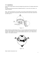
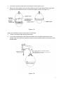
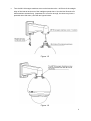
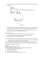
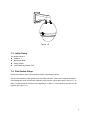
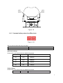
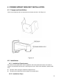
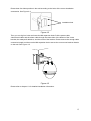
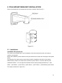
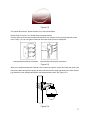
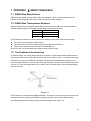
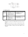
Integrated Intelligent Speed Dome Installation Manual Version 1.0 Table of Contents 1 INTELLIGENT SPEED DOME INSTALLATION................................................. 1 1.1 Installation Preparation................................................................................................................. 1 1.2 Installation....................................................................................................................................... 2 1.3 Initial Setup ..................................................................................................................................... 6 1.4 Dial Switch Setup ........................................................................................................................... 6 1.4.1 Communication protocol and Baud rate .................................................................................... 7 1.4.2 Address Setup ............................................................................................................................. 8 2 BRACKET DIMENSIONS ................................................................................. 10 2.1 Wall mount bracket ...................................................................................................................... 10 2.2 Corner mount bracket ................................................................................................................. 10 2.3 Pole mount bracket ..................................................................................................................... 11 3 WALL MOUNT BRACKET INSTALLATION .................................................... 12 3.1 Component Installation............................................................................................................... 12 3.2 Installation..................................................................................................................................... 12 3.2.1 Installation Requirements ......................................................................................................... 12 3.2.2 Installation Steps ....................................................................................................................... 12 4 CORNER MOUNT BRACKET INSTALLATION ............................................... 14 4.1 Component Installation............................................................................................................... 14 4.2 Installation..................................................................................................................................... 14 4.2.1 Installation Requirements ......................................................................................................... 14 4.2.2 Installation Steps ....................................................................................................................... 14 5 POLE MOUNT BRACKET INSTALLATION..................................................... 16 5.1 Installation..................................................................................................................................... 16 Installation Requirements ....................................................................................................................... 16 ii 6 APPENDIX Ⅰ THUNDER PROOF AND SURGE PROTECTION ....................... 19 7 APPENDIX Ⅱ ABOUT RS485 BUS.................................................................. 20 7.1 RS485 Bus Main Feature ............................................................................................................ 20 7.2 RS485 Bus Transmission Distance .......................................................................................... 20 7.3 The Problem in Practical Use .................................................................................................... 20 7.4 RS485 Bus FAQ ............................................................................................................................ 21 iii Welcome Thank you for purchasing our speed dome! Please read the following safeguards and warnings carefully before you install or use the product! iv Important Safeguards and Warnings Safety Measures Qualified Engineer Needed The installation engineer or maintenance engineer shall have corresponding CCTV system installation certificate or maintenance qualification certificate. The installation engineer or maintenance engineer shall have qualification certificate for work at height. The installation engineer or maintenance engineer shall have the basic knowledge and operation technique for low-voltage cable layout and low-voltage electronic cable connection. Please read the installation manual carefully and keep it well for future reference, We are not liable for any problems caused by unauthorized modifications or attempted repair. Lifting Appliance Requirement Please select the proper speed dome installation mode and use the lifting appliances at the safety environment. The lifting appliances shall have the enough capacity to reach the installation height. The lifting appliances shall have safe performance. Precautions Safety Transportation Heavy stress, violent vibration or water splash are not allowed during transportation, storage and installation. This series product must use split type package during the transportation. We are not liable for any damage or problem resulting from the integrated package during the transportation. When device is malfunction Shut down the device and disconnect the power cable immediately if there is smoke, abnormal smell or abnormal function. Please contact your local retailer ASAP. Do not try to dismantle or modify the device There is risk of personal injury or device damage resulting from opening the shell. v Please contact your local retailer if there is internal setup or maintenance requirement. We are not liable for any problems caused by unauthorized modifications or attempted repair. Do not allow other object falling into the device Please make sure there is no metal or inflammable, explosive substance in the speed dome. The above mentioned objects in the device may result in fire, short-circuit or damage. Please shut down the device and disconnect the power cable if there is water or liquid falling into the camera. Please contact your local retailer ASAP. Please pay attention to the camera. Avoid the sea water or rain to erode the camera. Handle carefully Do not allow this series product fall down to the ground. Avoid heavy vibration. Installation Environment Requirement This series speed dome should be installed in a cool, dry place away from direct sunlight, inflammable, explosive substances and etc. This series product shall be away from the strong electromagnetism radiant, please keep it away from wireless power, TV transmitter, transformer and etc. Daily Maintenance Please use the soft cloth to clean dust on the shell, or you can use soft cloth with cleaning liquid to clean the shell and then use soft cloth to make it dry. Do not use gasoline, dope thinner or other chemical material to clean the shell. It may result in shell transfiguration or paint flake. Do not allow the plastic or rubber material to touch the shell for a long time. It may result in paint flake. vi 1 INTELLIGENT SPEED DOME INSTALLATION 1.1 Installation Preparation Basic Requirement All installation and operation here should conform to your local electrical safety codes. Before installation, please open the package and check all the components are included. Please make sure the speed dome installation environment and installation mode can meet your requirement. If there is special requirement, please contact your local retailer for more information. We assume no liability or responsibility for all the fires or electrical shock caused by improper handling or installation. Check installation space and installation location intension Please make sure the installation environment has enough space to install the speed dome and its corresponding bracket. Please make sure the ceiling, wall and the bracket can support the speed dome and its corresponding installation component. The safety factor shall be 8X. About cable Please select the cable according to your transmission distance. The minimum video coaxial-cable requirement is: 75 ohm. Full cable with copper conductor 95% knitted copper shield International Model RG59/U RG6/U RG11/U Max Distance (Ft\M) 750ft (229m) 1,000ft (305m) 1,500ft (457m) Set dial switch button Set dial switch button according to control protocol and speed dome address. (Please refer to user’s manual for detailed information.) Please keep all package material well for future use Please keep speed dome package material well in case you need to send it back to your local retailer or manufacturer for maintenance work. Non-original package material may result in device damage during the transportation. Check Accessories Before the installation, please check the accessories one by one according to the packing list. Please make sure all the components listed are includes. Important: The speed dome power is AC 24V. 1.2 Installation Please note the speed dome includes the intelligent high speed dome, IP intelligent speed dome, and etc. The speed dome has several types of installation brackets. You can refer to the chapter 3 for detailed information. Step1: Open the transparent cover and take out the packing material EPE around the speed dome driver. Please remove the protective paster from the driver and take off the camera lens cap. See Figure 1-1. Figure 1-1 Step2: Set address and Baud Rate. Now you can set the intelligent speed dome address and baud rate. The speed dome interface is shown as below. See Figure 1-2. There are two dial switches: SW2 and SW3. Here you can set the address, baud rate, and etc. Please refer to chapter 1.4 for detailed information. Figure 1-2 Step3: Install the transparent cover 2 a. b. You need to check the steel wire of the bracket is firmly secure or not. Please line up the captive screws to the quadrate groove of the bracket and then push the bracket into the internal enclosure. Fix these two captive screws. See Figure 1-3. Figure 1-3 Step4: (the installation steps of using wall mount bracket) a. Take the composite cable through the bracket b. Line up the straight edge of the internal enclosure of the intelligent speed dome to the straight edge of the wall mount bracket, and then push the speed dome to the bottom of the bracket slowly. Figure 1-4 3 c. Turn the M6*16 hexagon stainless screw on the bracket to the Ф6.5 hole of the straight edge of the internal enclosure of the intelligent speed dome. Use the Hex Wrench to fix these stainless screws firmly. (Important! If it is not firm enough, the dome may have a potential risk to fall down.) See the two figures below. Figure 1-5 Figure 1-6 4 d. Use the hex wrench to turn another two M6*10 hexagon stainless screws and cushions complete firmly. Figure 1-7 e. After installation, use hex wrench to fix the M6 stainless screws (3 in total) for the last time to make sure these three M6 stainless screws have been completely fixed so that the intelligent dome could be completely installed to the bracket (Important! If it is not firm enough, the dome may have a potential risk to fall down.) Step5: Fix the dome a. Choose the wall to install; the wall shall be thick enough to install expansion bolt. b. The wall shall be capable of bearing 8 times of the weight of accessories. c. Please refer to chapter 3 for detailed installation. Step6: Wire connection: Connect the multi-functional composite cable to the corresponding power cable, video output cable, RS485 control cable, alarm I/O terminal, then paste the insulating tape in the connection position to be waterproof. Note: The video port is covered the heat shrink tube of high shrinking ratio. After the video connection, please heat the tube to make sure the video port is damp proof and water proof. Step7: Now the installation is completed. Important After the installation, please make sure: The three stainless screws of the quick installation port are firmly secure. The quick installation speed dome is fixed. The speed dome is straight. The steel wire connection is firm. After your installation, the interface is shown as below.. 5 Figure 1-8 1.3 Initial Setup The default setup is: Address: 1 Baud rate: 9600 Parity: NONE 120Ω Matching resistor: OFF 1.4 Dial Switch Setup Please set address, baud rate and parity before controlling the dome. The two dial switches of the speed dome are SW2 and SW3. These are to specify the speed dome parameter such as baud rate, address, parity and etc. When the button is ON, it is 1. In SW2, 1 is the lowest bit and the 8 is the highest bit. In SW3, 1 is the lowest bit and the 4 is the highest. See Figure 1-9. 6 SW2 SW3 Figure 1-9 1.4.1 Communication protocol and Baud rate Figure 1-10 SW3 is used for baud rate setup and parity. Baud rate Parity 1,2 3.4 Baud rate settings Please refer to the sheet below for detailed information. 1 2 Baud rate OFF OFF 9600bps ON OFF 4800bps OFF ON 2400bps ON ON 1200bps Parity settings Please refer to the sheet below for detailed information. 3 4 Parity 7 OFF OFF NONE ON OFF EVEN OFF ON ODD ON ON NONE 1.4.2 Address Setup The speed dome address setup interface is shown as below. See Figure 1-11. Figure 1-11 SW2 is used for address setup. The dome use dial switch to set address and the encode mode adopts binary system. 1 to 8 is valid bit. The highest address bit is 255. You can refer to the following sheet for more information. Address 1 1 1 2 3 4 5 6 7 8 …… 254 255 2 3 4 5 6 7 8 OFF OFF OFF OFF OFF OFF OFF OFF ON OFF OFF OFF OFF OFF OFF OFF OFF ON OFF OFF OFF OFF OFF OFF ON ON OFF OFF OFF OFF OFF OFF OFF OFF ON OFF OFF OFF OFF OFF ON OFF ON OFF OFF OFF OFF OFF OFF ON ON OFF OFF OFF OFF OFF ON ON ON OFF OFF OFF OFF OFF OFF OFF OFF ON OFF OFF OFF OFF ………………………………………………………………… OFF ON ON ON ON ON ON ON ON ON ON ON ON ON ON ON 1.4.3 Terminal matching resistor settings Terminal matching resistor is on power-supply board and there are two ways to connect. Please see the figure below for reference. J6 120Ω 1-2 ON 2-3 OFF Figure 1-12 8 The following figure shows the factory default mode. You can see the jumper cap (connection board) is inserted into the socket NO.2 and NO.3; 120Ω resistance has not been connected to then, 1 2 3 J6 Default jump settings(120Ω resistance has not been connected to) Figure 1-13 Pull the jumper cap off the socket NO.2 and NO.3 and then insert into socket NO.1 ~ NO.2 if 120Ω resistance is needed to be connected to the electric circuit. See the figure below for reference. 1 2 3 J6 Jump settings (120Ω resistance has been connected to) Figure 1-14 9 2 BRACKET DIMENSIONS 2.1 Wall mount bracket The wall mount bracket dimensions are shown as below. See Figure 2-1. Figure 2-1 2.2 Corner mount bracket The corner mount bracket is shown as below. See Figure 2-2. 10 Figure 2-2 2.3 Pole mount bracket The corner mount bracket is shown as below. See Figure 2-3. Figure 2-3 11 3 WALL MOUNT BRACKET INSTALLATION 3.1 Component Installation Wall mount bracket is shown as below. See Figure 3-1. Figure 3-1 3.2 Installation 3.2.1 Installation Requirements The wall mount speed dome can be installed in the hard construction wall in the indoor or outdoor environments. Before the installation, please make sure: The wall is thick enough to install the expansion bolt. The wall can at least bear the 8x weight of the speed dome. 3.2.2 Installation Steps Please draw four holes position in the wall according to the hole of the bottom of the wall mount bracket. Then you can dig four holes and insert the expansion bolts (not provided). Use four hex bolts and flat washer to fix the bracket in the expansion bolts. Figure 3-2 12 Finish the installation. See Figure 3-3. Figure 3-3 Please refer to chapter 1.2 for detailed installation information. 13 4 CORNER MOUNT BRACKET INSTALLATION 4.1 Component Installation Corner mount bracket and its components are shown as below. See Figure 4-1. Figure 4-1 4.2 Installation 4.2.1 Installation Requirements The corner mount speed dome can be installed in the hard construction wall in the indoor or outdoor environments where there is a 90 degrees angle. Before the installation, please make sure: The wall is thick enough to install the expansion bolt. The wall can at least bear the 8x weight of the speed dome. 4.2.2 Installation Steps 14 Please draw four holes position in the wall according to the holes of the corner installation accessories. See Figure 4-2. Installation hole Figure 4-2 Then you can dig four holes and insert the M8 expansion bolts. Pull the power cable, video/control cable and the alarm cable through the centre hole of the bottom of the corner bracket, the waterproof adhesive, and the centre of the bracket. Please reserve the enough cable connection length and then use the M8 expansion bolt to secure the corer mount bracket chassis on the wall. See Figure 4-3. Figure 4-3 Please refer to chapter 1.2 for detailed installation information. 15 5 POLE MOUNT BRACKET INSTALLATION Pole mount bracket and its components are shown as below. See Figure 5-1. Figure 5-1 5.1 Installation Installation Requirements The corner mount speed dome can be installed in the hard construction wall in the indoor or outdoor environments. Before the installation, please make sure the pole bracket can sustain the 8X weight of the speed dome. The diameter of the pole structure shall comply with the installation dimension of the clamp. Default factory clamp is six inches for the column of φ130-152mm. It can work with the pole installation bracket. You can adjust the diameter and the value (clamp specification) is : φ5982mm、φ84-108mm、φ103-127mm, φ130-152mm、φ155-178mm、φ180-203mm,φ194-216mm. The clamp is shown as in Figure 5-2. 16 Figure 5-2 For special dimensions, please contact us for more information. Please refer to Figure 5-3 to install clamp and pole bracket. Pull the cable out of the pole accessories and then use clamp to fix the pole accessories to the pole. Finally, you can use glass cement to the output hole to secure waterproof. Clamp and pole bracket connection Pole bracket and the pole connection Figure 5-3 After you installed bracket and external cover, loosen the captive screws and open the panel, pull the power cable through the hanging bracket and then fix the hanging bracket to the wall. Please pay attention to the waterproof between the bracket and the wall. See Figure 5-4. Figure 5-4 17 Please refer to chapter 1.2 for detailed installation information. 18 6 APPENDIX Ⅰ THUNDER PROOF AND SURGE PROTECTION This series speed dome adopts TVS lighting protection technology. It can effectively prevent damages from various pulse signals below 1500W, such as sudden lighting and surge. While maintaining your local electrical safety code, you still need to take necessary precaution measures when installing the speed dome in the outdoor environment. The distance between the signal transmission cable and high-voltage device (or high-voltage cable) shall be at least 50 meters. Outdoor cable layout shall go under the penthouse if possible. For vast land, please use sealing steel tube under the land to implement cable layout and connects one point to the earth. Open floor cable layout is forbidden. In area of strong thunderstorm hit or near high sensitive voltage (such as near high-voltage transformer substation), you need to install additional high-power thunder protection device or lightning rod. The thunder protection and earth of the outdoor device and cable shall be considered in the building whole thunder protection and conform to your local national or industry standard. System shall adopt equal-potential wiring. The earth device shall meet anti-jamming and at the same time conforms to your local electrical safety code. The earth device shall not short circuit to N (neutral) line of high voltage power grid or mixed with other wires. When connect the system to the earth alone, the earth resistance shall not be more than 4Ω and earth cable cross-sectional area shall below 25 mm2. See Figure 6-1. Figure 6-1 19 7 APPENDIX Ⅱ ABOUT RS485 BUS 7.1 RS485 Bus Main Feature RS485 is semi duplex communication cable of impedance 120Ω. Its max load amount is 32 effective loads (including main control device and devices to be charged). 7.2 RS485 Bus Transmission Distance When we take 0.56mm (24AWG) twisted-pair as communication cable, the max transmission distance (theoretically) are listed below (according to different baud rates). Baud Rate Max Distance 2400 BPS 1800M 4800 BPS 1200M 9600 BPS 800M In the following situations, the max transmission distance shall become shorter accordingly: The communication cable is a little bit thin; The surrounding environment has strong electromagnetic interference; There are too much devices connected to the RS485 bus; And vice versa, the max transmission distance shall become longer. 7.3 The Problem in Practical Use In practical usage, we usually adopt star type connection. The terminal resistance shall connect to the furthest two devices (Such as device 1# and device 15# in Figure 7-1 ). But this connection way does not conform to RS485 Bus standard. When the distances between devices are too long, the signal reflection occurs and anti-jamming decreases, thus the signal reliability becomes very low. You can see speed dome is not under control or speed dome is running automatically and can not stop. Figure 7-1 In this situation, we recommend RS485 distributor. This device can turn star type connection into the connection that conforms to RS485 bus industry standard, which can avoid the above mentioned problems and enhance communication reliability. See Figure 7-2. 20 Figure 7-2 7.4 RS485 Bus FAQ Phenomenon Speed dome can run selfdiagnosis but I can not control it. I can control the speed dome but is not smooth Possible Reasons Host address(baud rate) and speed dome address(baud rate) are not match; Positive and negative end of RS485 Bus are misconnected; Connection cable is loose; RS485 Bus connection are cut off; RS485 Bus connection are not good; One RS485 bus is off; The distance between host and speed dome is too far; Parallel connected too much speed domes. Solution Modify host or speed dome setup ; Switch RS485 positive end and negative end; Fix connection cable firmly; Replace RS485 Bus. Connect RS 485 Bus again; Replace RS485 Bus; Add terminal matching resistance; Add RS485 distributor. Note This manual is for reference only. Slight difference may be found in the user interface. All the designs and software here are subject to change without prior written notice. If there is any uncertainty or controversy, please refer to the final explanation of us. Please visit our website or contact your local service engineer for more information. 21