1
percussion synthesizer and sampler
user manual
copyright LinPlug Virtual Instruments GmbH
all rights reserved
virtual drum machine
percussion synthesizer and percussion sampler
user manual
copyright LinPlug Virtual Instruments GmbH
all rights reserved
concept Peter Linsener
programming Peter Linsener : Bo Johansen
graphics decoderdesign.com
drum kits The Electronic Garden : Groove Criminals : Kohlekeller Studio : Manytone
Music : kenfen.com : dubhad
manual Chris Share
we say thanks to our beta test team, to all who helped with their comments to build
the RMIV and to all customers for supporting us over the years
LinPlug : Bo Johansen : Chris Share : Ken Fennell : Peter Linsener
RM IV user manual : version 1.1
page 2
Welcome
Thank you for buying the RM IV.
The RM IV is a fully professional, highly-flexible, easy-to-use, fourth-generation virtual
drum machine designed for creating music on your personal computer.
The RM IV combines analog-style percussion synthesis with a fully-featured percussion
sampler. The instrument combines many of the features found on the LinPlug RM III and
CM-505, however it also includes several new and innovative features not found on either
of these instruments.
The RM IV's key features include 18 velocity-sensitive Drum Pads, each which can be
used to trigger any one of a range of high quality audio generator modules (a selection of
percussion synthesis modules and a sophisticated percussion sampler module), an
AHDSR-controlled multi-mode filter, a fully-featured Compressor designed specifically for
percussion sounds, a flexible "Varizer" and 2 effects processors (Distortion and
BitCrusher) all of which can be set on a per-Pad basis. The RM IV also features a 6 x 6
Modulation Matrix, 32-voice polyphony (selectable per Pad), as well as separate Volume,
Output, Tune, Pan, Choke, Mute and Solo controls for each Pad.
This manual describes all aspects of the RM IV drum machine and is designed so that
your use of this software is as efficient and as pleasurable as possible.
We feel that the RM IV is exceptional because of its audio quality, its wide range of
features and its sonic potential. We hope you get a lot of pleasure using the RM IV drum
machine and that it becomes an important part of your music-making.
July 2003
LinPlug : Bo Johansen : Chris Share : Ken Fennell : Peter Linsener
All technical specifications of the products specified in this manual may be subject to change without notice.
The documents may not be changed, especially copyright notices may not be removed or changed. LinPlug
and all LinPlug product names are trademarks of LinPlug Virtual Instruments GmbH. Cubase and VST are
registered trademarks of Steinberg Media Technologies AG. All other trademarks are the property of their
respective owners.
RM IV user manual : version 1.1
page 3
Table of Contents
INSTALLATION.........................................................................................................6
FEATURES/SPECIFICATIONS.................................................................................8
WHAT'S NEW IN THE RM IV....................................................................................9
QUICKSTART..........................................................................................................10
OVERVIEW.............................................................................................................13
CONTROLS.............................................................................................................14
DRUM PADS...........................................................................................................15
AUDIO GENERATOR MODULES...........................................................................18
PERCUSSION SYNTHESIS MODULE...................................................................18
KICK 1...........................................................................................................19
KICK 2...........................................................................................................20
SNARE 1.......................................................................................................21
SNARE 2.......................................................................................................22
TOM..............................................................................................................23
OPEN/CLOSED(HI)HAT...............................................................................24
RIDE CYMB(AL)...........................................................................................25
CYMBAL 2....................................................................................................26
CLAPS..........................................................................................................27
PLOP............................................................................................................28
SAMPLER MODULE..............................................................................................29
SAMPLE DISPLAY.......................................................................................30
PITCH ENVELOPE.......................................................................................34
AMPLITUDE ENVELOPE.............................................................................35
FILTER....................................................................................................................36
COMPRESSOR.......................................................................................................38
VARIZER.................................................................................................................39
EFFECTS................................................................................................................40
MODULATION MATRIX..........................................................................................41
KIT BROWSER........................................................................................................42
THE RM IV KITS......................................................................................................44
MIDI BROWSER......................................................................................................45
ECS (EASY CONTROLLER SETUP)......................................................................47
REAR PANEL..........................................................................................................48
RM IV user manual : version 1.1
page 4
GET THE FULL VERSION......................................................................................51
APPENDIX A: MODULATION SOURCES AND DESTINATIONS...........................52
MODULATION SOURCES...........................................................................52
MODULATION DESTINATIONS...................................................................53
GLOSSARY.............................................................................................................55
MIDI IMPLEMENTATION CHART...........................................................................57
RM IV user manual : version 1.1
page 5
Installation
Installation on PC
The RM IV comes with its own Installer. On the RM IV CD you will find a file named
"RMIVInstaller.exe". Double-click on this program to begin the installation process. The
Installer will guide you through the installation process. Make sure you choose the right
directory, so you host software finds the RM IV VSTi.
Refer to your host software's manual if you are unsure about where the host software plugin directory is located.
The instrument file "RM IV.dll" will be placed in the chosen directory. The next time you
start your host software the RM IV will be listed in the VST Instrument list.
To install the RM IV Kits open the RMIVKits.zip archive by double clicking it. Uncompress
it to the same folder where you installed the RM IV instrument. Be aware you are installing
around one gigabyte of data now, so this may take some time.
You can install the RM IV Kits to a different location of course, this only means RM IV will
not automatically load the first kit when a new RM IV is opened in your host. Once you
load the first kit manually, you will be able to browse the RM IV Kits as usual no matter
where they are located.
To install the RM IV Grooves open the RMIVGrooves.zip archive by double clicking it.
Uncompress it to the same folder where you installed the RM IV instrument.
You can install the RM IV Grooves to a different location of course, this only means RM IV
will not automatically load the first groove when a new RM IV is opened in your host. Once
you load the first groove manually, you will be able to browse the RM IV Grooves as usual
no matter where they are located.
Installation on Mac
The RM IV comes with its own Installer. On the RM IV CD you will find a file named "RM IV
Installer.dmg". Double-click this file to decompress and open the image, then double-click
the installer program to begin the installation process.
You will be guided through the installation process. The RM IV instrument files will now be
placed in the right directory for virtual instruments (VST and AU) on your Mac. The next
time you start your host software the RM IV will be available in the instrument list.
To install the RM IV Kits open the RMIVKits.zip archive by double clicking it. Uncompress
it to /Library/Application Support/LinPlug. Be aware you are installing around one gigabyte
of data now, so this may take some time.
You can install the RM IV Kits to a different location of course, this only means RM IV will
not automatically load the first kit when a new RM IV is opened in your host. Once you
load the first kit manually, you will be able to browse the RM IV Kits as usual no matter
where they are located.
To install the RM IV Grooves open the RMIVGrooves.zip archive by double clicking it.
Uncompress it to /Library/Application Support/LinPlug.
You can install the RM IV Grooves to a different location of course, this only means RM IV
will not automatically load the first groove when a new RM IV is opened in your host. Once
you load the first groove manually, you will be able to browse the RM IV Grooves as usual
no matter where they are located.
RM IV user manual : version 1.1
page 6
Common to Mac and PC
After you've installed and opened the full version of the RM IV, go to the instrument's rear
panel. The S/N edit box should read "Enter here". Enter the serial number you have
received into the S/N edit box. If the serial number has not been entered or it has been
entered incorrectly, the full version of the RM IV will not play any notes. To switch back to
the main edit screen click the LinPlug or RM IV logos on the rear panel.
After entering the serial number return to the RM IV's front panel. Now send the RM IV a
few note-on messages. After the RM IV receives the first few note-on messages it
automatically becomes registered. After registration, the S/N field is no longer editable.
You can confirm this by looking at the S/N field on the instrument's rear panel.
If you have any questions regarding the installation of RM IV please contact our support
team at www.linplug.com/support/support.htm.
RM IV user manual : version 1.1
page 7
Features/Specifications
The RM IV contains a range of features designed to make your music-making more
efficient and enjoyable. These features are described below:
drum synthesis and sample plugin for Mac OSX and PC.
Designed for drums but can be used for pitched samples as well.
The instrument is Multitimbral with each pad having its own MIDI channel.
True stereo sample playback and processing (all filters and effects are mono and
stereo).
Professional user interface providing direct access to controls with the minimum
number of mouse-clicks.
18 polyphonic Drum Pads.
Up to 32-voice polyphony (selectable per Drum Pad).
Multiple instances of the instrument can be opened.
A wide range of different Audio Generator modules which include:
An extensive selection of percussion synthesis modules.
A sophisticated percussion sampler module.
2 different Kick drum modules.
2 different Snare drum modules.
Open and Closed HiHat module
Tom module.
Clap module.
2 Cymbal modules
Plop Percussion module.
Each Drum Pad includes its own controls for Output Destination, Vol(ume), Pan,
(only if routed to a Stereo output), Tune (+- 24 semitones in 10 cent intervals),
Choke Group (5 groups are available including prev/next and self-mute),
Polyphony (mono...8, full), Mute and Solo and a MIDI activity display.
For each Drum Pad the user has access to a multi-mode AHDSR-controlled filter,
a Compressor with controls for Ratio, Threshold and Release, a "Varizer" with
controls for Style, Precision and Spectrum, a 6 x 6 Modulation Matrix and two
separate effects processors (Distortion and BitCrusher).
Drum Pad Displays automatically switch upon editing allowing exact adjustment of
level, pan and tuning and other parameters.
Each Sampler module can hold up to 30 samples that can be individually triggered.
Samples on each Drum Pad can have individual volume settings and can be
layered or velocity-switched or velocity-crossfaded.
Samples can be played forwards or backwards.
Waveform Display which shows Waveform, the effect of the Pitch Envelope,
Amplitude Envelope and Filter Envelope.
The Amplitude Envelope Release Time can be set to "endless", so that even long
samples won't be cut off.
Samples can be browsed while playing your music.
Kits can be browsed while playing your music.
Supported sample formats: WAV 8-32 bit, mono and stereo, any samplerate, AIF
8-24 bit, mono and stereo, any samplerate, WAV 32 bit float WAV, mono and
stereo, any sample rate.
Supported Kit Formats: RM IV, RM III, CM-505, RM 2, LM 4.
The file path to samples and kits is remembered for the next time you open the file
dialog.
RM IV user manual : version 1.1
page 8
Several parameters are conveniently located on the "Rear Panel" so they are not
changed accidentally during use.
Two pan modes are available: Equal Voltage (mono compliant) and Equal Power.
Optional Drum Pad velocity sensitivity.
Switchable linear or circular dial response.
Display can show either note numbers or note names.
Adjustable velocity response curve.
Freely assignable output configuration up to 18 stereo or mono outputs.
Adjustable voice limit (mono...1...8, full).
All Parameters are MIDI controllable and automateable (VST automation).
Controller hardware (faderbox or synth) settings can be saved and restored using
ECS (Easy Controller Setup).
ECS supports conventional and Alpha Dial controller.
Internal 32/64 bit processing.
Dynamic resource allocation (unused components are switched off automatically)
for minimum CPU usage.
Sample accurate timing.
What's New In The RM IV
In comparison with its predecessors the RM III, the RM IV contains a host of new features
intended to make your music-making more efficient and enjoyable. These new features
are listed below:
Contains over 120 Kits including all RM 2 Kits, all RM III Kits, a whole bunch of
multisampled acoustic kits, new dance kits and many, many synthesized kits.
Loads all CM-505 kits accurately.
Each Drum Pad can use any one of a wide selection of different synthesis
algorithms including percussion synthesis algorithms and an Intelligent Sampler.
Varizer effect with adjustable Style, Accuracy and Spectrum parameters.
6 x 6 Modulation Matrix with Filter and Amplitude envelopes available as
destinations.
Sample Display which shows Waveform, Pitch Envelope, Amplitude Envelope
and Filter Envelope.
Fully-featured, improved Multimode filter with low pass, high pass, band pass
and band reject modes, each with 12 and 24 dB slopes.
Kit Name display.
Enhanced ECS (Easy Controller Setup) featuring Learn, Clear and Clear All
commands.
Improved Pitch Envelope with two successive Pitch and Time phases.
AHDSR Envelope for controlling Amplitude.
Invertable AHDSR Envelope for controlling Filter Cutoff Frequency.
Adjustable polyphony per Drum Pad.
Fully-featured customized drum compressor.
Switchable Velocity-sensitive Drum Pad Trigger buttons.
Waveform Start parameter with optional snap-to-zero-crossing point.
Support for multiple soloing of Drum Pads.
Mouse-wheel support (on PC).
RM IV user manual : version 1.1
page 9
Quickstart
The RM IV has been designed to be very easy to use. Using the procedure outlined below
you should be able to start making music with the RM IV in a few minutes. After you've
installed the RM IV (as detailed in the previous section) and opened the host program
here's what to do:
1. Create a MIDI drum pattern in the host software. For this example, make a
pattern with just kick and a snare. Alternatively, you can open a pre-existing MIDI
track. If you use the drum editor in Cubase SX it will look like the image below.
2. Load the RM IV into the host software. Check the host software manual for
instructions on how to do this. For example, in Cubase SX go to the devices
menu ->VST Instruments. Assign the output of the MIDI part that you have just
created to the RM IV. When using Cubase SX, MIDI output assignment is set in
the Inspector section of the Arrange window. This is shown below.
RM IV user manual : version 1.1
page 10
3. Open the RM IV Edit window. Click on the Trigger Button for Drum Pad 2. This
enables you to see the synthesis method that this pad is currently using. To
assign a synthesis algorithm to a Drum Pad use the Module control located
directly above Drum Pad 1. First, select the Drum Pad, and then select one of the
RM IV's Audio Generator modules from the drop down list in the Module control.
The module will now be assigned to the Pad. Using this method, set Drum Pad
1's synthesis algorithm to the Kick 1.
4. Set Drum Pad 6's synthesis method to the Sampler. With Drum Pad 6 selected,
click on the "directory" icon in the file section of the Sample Display. The Sample
Display is shown in the top left corner of the RM IV when the selected Pad is set
to the Sampler algorithm. A file dialog will open. Choose the sample you wish to
RM IV user manual : version 1.1
page 11
load. Note that the RM IV can load WAV and AIFF samples. You will find
samples in the RM IV Kits folder by clicking a folder named "... Samples".
5. For each of the Drum Pads mentioned above, check that the Drum Pad's trigger
key corresponds to the note number for each drum part you entered in step one.
For example, if your MIDI kick drum notes are set to Key 36 (Note C1), make
sure that Drum Pad 1 is triggered by Key 36 (Note C1). You can set this for
synthesized drums on the RM IV's Rear Panel in the Settings Display. To go to
the Rear Panel, click on either the "LinPlug" or "RM IV" logos. To return to the
Front Panel from the Rear Panel, click on either the "LinPlug" or "RM IV" logos.
To change the Trigger note for samples click in the Key column on the Samples
window and drag the mouse up and down.
6. Start playback of the drum pattern. You should now hear the RM IV playing back
the drum pattern you created in step 1. Congratulations! You've just created
your first drum loop with the RM IV.
RM IV user manual : version 1.1
page 12
Overview
The RM IV is a 32 note-polyphonic VST drum synthesizer. The instrument is designed
specifically for creating and playing synthetic percussion sounds, as well as playing
sampled percussion sounds.
The synthesis algorithms used in the RM IV have their roots in classic analogue drum
machines like the Roland TR808 and TR909. However, while the RM IV can replicate
many of the sounds of these classic analogue drum machines, it also extends them into
new sonic territory and so has far greater creative potential.
The RM IV consists of 18 Drum Pads, each of which uses one of the instrument's Audio
Generator modules (this can be one of the percussion synthesis modules or the Sampler
module) to generate sound. Each Pad has its own dedicated set of controls which include
Display, Pan, Tune, Volume, Output, Choke Mode, Mute, Solo and Trigger. Each Drum
Pad also incorporates two insert effects, a compressor, a Varizer and an AHDSRcontrolled multi-mode filter.
The RM IV is divided into 10 sections: Audio Generator Module, Drum Pad, Filter, Filter
Envelope, Compressor, Varizer, Effects, Modulation Matrix, Kit and Rear Panel.
Audio signals are generated by any one of the RM IV's Audio Generator modules (one of
the percussion synthesis modules or the Sampler module) which get trigger information
from the synthesizer's MIDI input or from mouse-clicks on a Drum Pad's Trigger button.
The RM IV receives MIDI on all Channels simultaneously unless you change this on the
rear panel.
The RM IV uses Audio Generator modules to generate sound. These modules use drum
synthesis algorithms, as well as sampling, to generate sound. The various parameters for
the synthesis algorithms, which differ according to the individual algorithm, can be set in
the RM IV's Audio Generator section. The parameters for the Sampler module can also be
set in this part of the RM IV.
The RM IV's Sampler module can be used to load up to 30 samples into an individual
Drum Pad. It can also be used to view the samples once they are loaded. The Sampler
module is made up of three separate components: The Sample Display, The Pitch
Envelope and the Amplitude Envelope. The Sample Display shows various parameters for
the currently-loaded sample/s. It can also be used to show the sample's envelope settings
(Pitch, Amplitude and Filter) which greatly assists in setting their various parameters. The
Sampler module has two envelopes available for each Drum Pad: Pitch and Amplitude. It's
important to note that these envelopes apply to all of the samples currently loaded into the
Drum Pad.
The RM IV features 2 independent effects units: BitCrusher and Distortion. The output of
each Drum Pad is automatically routed to these processors. As mentioned above, all
processors function as "insert" effects. This means that their parameters can be set
independently for each of the RM IV's 18 Drum Pads.
The RM IV also features a multi-mode AHDSR-controlled filter that can be set uniquely for
each Pad. Also available on a per-Pad basis is a Compressor with controls for Ratio,
Threshold and Release, and a "Varizer" with controls for Style, Precision and Spectrum.
RM IV user manual : version 1.1
page 13
The audio outputs of the RM IV are automatically connected to the input of your host
software's mixer. The number and configuration of the RM IV's audio outputs can be set
on the instrument's Rear Panel (see below for an explanation of the RM IV's Rear Panel)
to any combination of mono and stereo outputs that the user desires.
Finally, the RM IV's Rear Panel allows you to set various global parameters including
Power Pan, Pad Velocity, Dial Mode, Note Names, Choke Mode as well as each Drum
Pad's Polyphony, MIDI Channel, Root Note and Trigger Note.
Hopefully, this chapter has given you a brief overview of how the RM IV works. More
detailed information can be found in the following chapters.
Controls
Users have the option of controlling all RM IV dials in either a circular or a linear manner
depending on the Dial Mode setting on the RM IV's Rear Panel (see the "Rear Panel"
section of this manual for more information).
Holding down the ALT key while clicking on a control changes the selected control's value
a minimum step upwards (when clicking in the upper half of the control) or a minimum step
downwards (when clicking in the lower half of the control).
Holding down the CTRL key while clicking on a control sets the control to its default value
(e.g. for Volume controls it sets the control's value to -3 dB).
When controls are changed, the value of the control is displayed in the corresponding
Drum Pad's Display control. After a short period of time the Display controls revert to
showing the title of the respective Drum Pad. This applies to all RM IV controls except
those found in the Audio Generator Modules.
All controls can be automated and controlled using external MIDI messages. To use
external devices you need to use the RM IV's ECS which is described in detail later in this
manual.
PC users who have a mouse with a wheel can use the mouse-wheel to change RM IV
parameter values provided that the host software supports this (an example of a VST host
program that supports the use of mouse-wheels is Cubase SX).
RM IV user manual : version 1.1
page 14
Drum Pads
The RM IV contains 18 Drum Pads. Each Drum Pad can be used to trigger a particular
Audio Generator module (any one of the drum synthesis modules or the Sampler
module).
The currently selected Drum Pad is shown by a small Indicator Light located next to the
drum's name (see the Ride pad in the bottom row). To change to a different Drum Pad
click on any control or the trigger in the desired Drum Pad section. When you change
Drum Pad, the RM IV's display is updated so that it shows the Audio Generator module of
the currently selected Drum Pad.
The RM IV's 18 Drum Pads can be used to trigger any one of the RM IV's selection of
Audio Generator modules. The modules that use percussion synthesis algorithms to
generate sound are described in more detail in the Percussion Synthesis Module section
of this manual. One of the modules uses sampling to playback sounds. This module is
described in the Sample Module section of this manual.
To assign a synthesis algorithm to a Drum Pad use the Module control located directly
above Drum Pad 1. First, select the Drum Pad, and then select one of the RM IV's Audio
RM IV user manual : version 1.1
page 15
Generator modules. The module is now assigned to the Pad.
Each Drum Pad is identical and consists of 9 controls: Display, Pan,
Out(put), Choke, Tune, Vol(ume), Trigger, Mute and Solo. These
described in detail below.
Display/
Indicator:
The current settings for a Drum Pad can be named
using the Display control located at the top of the Pad.
The name of the Pad is saved with the Kit. When
various RM IV controls are used, their value is shown
in the Drum Pad's display. The Indicator (the small
green light on the left of the display) shows which Pad
is currently active. You can select a different Pad by
changing any parameter on another Instrument's Pad.
Pan: The Pan slider is used to set the stereo positioning of the Drum Pad's output and is
located below the Pad's Display. The control has a range of 1.00 L to 1.00 R.
A setting of "C" places the output in the centre of the stereo field. Note that if
the Drum Pad's output is set to a mono destination the Pan slider has no
effect.
Out(put):
The Out(put) control is used to set the output destination of the Drum Pad.
Available destinations depend upon the current audio output settings on the
RM IV's Rear Panel (for more information about the RM IV's Rear Panel, see
below). Note that all stereo outputs are listed first, followed by all of the
mono outputs.
Choke:
The Choke control lets you choose between the RM IV's various choke
modes. The available choke modes are:
"-"
No Choke is applied to this Pad.
"me"
Whenever this Pad is triggered, it chokes itself.
"prev"
Whenever this Pad is triggered, the Pad to the left of it is muted.
"nxt"
Whenever this Pad is triggered, the Pad to the right of it is muted.
"1"..."5" The RM IV has five user-definable choke groups. Whenever a Pad
in a particular choke group is triggered all other Pads in that choke
group are muted.
This is typically used to simulate the way that real drums generate sound.
For example, an open hihat is "choked" or muted when the drummer closes it
with the footpedal. As such, open and closed hihats often form a mute group.
Tune: The Tune control sets the Drum Pad's tuning. The available range is +- 24
semitones in 10 cent steps.
Vol(ume):
The Vol(ume) control is used to set the output volume of the Drum Pad. The
available range is -oo to +6 dB.
RM IV user manual : version 1.1
page 16
Trigger/
Activity:
The Trigger button allows the Drum Pad to be played using the mouse.
Simply click the mouse on the Drum Pad to trigger the sound. If Pad Velocity
is enabled on the RM IV's Rear Panel (see below for
more information about the RM IV's Rear Panel), the
Pad becomes velocity-sensitive. In this case, as the
mouse is moved from left to right over the Trigger
button, the trigger velocity increases. In other words,
clicking on the left of the button triggers the Pad at
lower velocities than clicking on the right of the Pad.
The Activity Indicator shows that the Pad has been
triggered. It stays lit until the Pad has finished playing.
Mute: The Mute button silences the output of the selected Drum
Pad.
Solo: The Solo button silences all Drum Pads other than the ones that are selected. This
is useful if you want to listen to particular combinations of drums in isolation.
RM IV user manual : version 1.1
page 17
Audio Generator Modules
The RM IV contains a range of different Audio Generator modules which it uses to create
and play percussion sounds. These include percussion synthesis modules as well as
sampling.
Each percussion synthesis algorithm is tailored to a particular type of percussion sound,
while the Sampler module can be used for playing back any type of sound you wish. The
Audio Generator Module used by the currently selected Drum Pad is shown in the top left
of the RM IV's front panel.
You will notice that some of the dials for the percussion synthesis algorithms have a ring
around them. This indicates that these controls are also found on the CM-505. Controls
without a ring around them are unique to the RM IV.
The RM IV's Audio Generator modules are described in more detail below.
Percussion Synthesis Module
Each percussion synthesis module uses a unique synthesis algorithm to generate sound,
and so has its own unique set of controls. The various synthesis algorithms used in the
RM IV's percussion synthesis modules are described in detail below:
RM IV user manual : version 1.1
page 18
Kick 1
The Kick 1 module contains controls for Pitch Env(elope) Depth, Pitch Env(elope) Decay
(Time), Pitch Env(elope) Shape, Osc(illator) Shape, Osc(illator) Frequency, Osc(illator)
Attack (Time), Osc(illator) Decay (Time), Noise Volume, Noise Colour and Noise Decay
(Time).
The Pitch Env(elope) Depth control determines the extent to which the drum's pitch is
controlled by the pitch envelope.
The Pitch Env(elope) Decay control is used to set the rate at which the drum's pitch
returns to the fundamental frequency.
The Pitch Env(elope) Shape control is used to set the shape of the drum's pitch envelope.
This can range from linear to extreme exponential.
The Osc(illator) Shape control is used to set the shape of the oscillator waveform. When
turned fully anti-clockwise the oscillator produces a sine wave, while when turned fully
clockwise the oscillator produces a pulse wave.
The setting of the Osc(illator) Frequency control determines the drum's fundamental
frequency. The frequency changes from low to high as the dial is turned in a clockwise
direction. This control interacts with the Tune control on the associated Drum Pad.
The Osc(illator) Attack (Time) control is used to set the drum oscillator's attack time.
Setting this control to a high value delays the onset of the drum waveform, creating
damping or muffling effects.
The Osc(illator) Decay (Time) control determines how fast the sound decays after it is
triggered. The decay time changes from short to long as the dial is turned in a clockwise
direction.
The Noise Volume dial is used to set the amount of noise added to the drum sound.
The Noise Colour dial setting determines the frequency spectrum of the noise and the
Noise Decay (Time) dial sets the decay time of the noise component of the drum sound.
RM IV user manual : version 1.1
page 19
Kick 2
The Kick 2 algorithm contains controls for Pitch Env(elope) Depth, Pitch Env(elope) Decay
(Time), Pitch Env(elope) Shape, Osc(illator) Shape, Osc(illator) Frequency, Osc(illator)
Decay (Time) and Noise Volume.
The Pitch Env(elope) Depth control determines the extent to which the drum's pitch is
controlled by the pitch envelope.
The Pitch Env(elope) Decay (Time) control is used to set the rate at which the drum's pitch
returns to the fundamental frequency.
The Pitch Env(elope) Shape control is used to set the shape of the drum's pitch envelope.
This can range from linear to extreme exponential.
The Osc(illator) Shape control is used to set the shape of the oscillator waveform. When
turned fully anti-clockwise the oscillator produces a sine wave, while when turned fully
clockwise the oscillator produces a pulse wave.
The setting of the Osc(illator) Frequency control determines the drum's fundamental
frequency. The frequency changes from low to high as the dial is turned in a clockwise
direction. This control interacts with the Tune control on the associated Drum Pad.
The Osc(illator) Decay (Time) control determines how fast the sound decays after it is
triggered. The decay time changes from short to long as the dial is turned in a clockwise
direction.
The Noise Volume dial is used to adjust the amount of noise added to the drum sound.
RM IV user manual : version 1.1
page 20
Snare 1
The Snare1 algorithm combines an oscillator with a noise source. The Snare1 algorithm
contains controls for Osc(illator) Shape, Osc(illator) Frequency, Osc(illator) Attack (Time),
Osc(illator) Decay (Time), Osc(illator) Volume, Osc(illator) Pitch Mod(ulation), Noise
Colour, Noise Res(onance), Noise Decay (Time) and Noise Env(elope) Mod(ulation).
The Osc(illator) Shape control is used to set the shape of the oscillator waveform. When
turned fully anti-clockwise the oscillator produces a sine wave, while when turned fully
clockwise the oscillator produces a pulse wave.
The setting of the Osc(illator) Frequency control determines the drum's fundamental
frequency. The frequency changes from low to high as the dial is turned in a clockwise
direction. This control interacts with the Tune control on the associated Drum Pad.
The Osc(illator) Attack (Time) control is used to set the drum oscillator's attack time.
Setting this control to a high value delays the onset of the drum waveform, creating
damping or muffling effects.
The Osc(illator) Decay (Time) control determines how fast the sound decays after it is
triggered. The decay time changes from short to long as the dial is turned in a clockwise
direction. The Osc(illator) Volume dial sets the volume of the pitched component of the
sound in relation to the noise component.
The Osc(illator) Pitch Mod(ulation) control is used to set the extent to which the drum's
pitch is controlled by the oscillator's pitch envelope.
The Noise Colour dial setting determines the frequency spectrum of the noise.
The Noise Res(onance) dial is used to set the amount of emphasis around the noise
oscillator's cutoff frequency. Higher settings create a more pronounced peak in the signal
while lower settings produce a flatter response.
The Noise Decay (Time) dial sets the decay time of the noise component of the drum
sound.
The Noise Env(elope) Mod(ulation) dial is used to set the degree to which the noise
oscillator's filter cutoff frequency is modulated by the oscillator's amplitude envelope.
RM IV user manual : version 1.1
page 21
Snare 2
The Snare 2 algorithm combines a noise oscillator and a pitched oscillator that
incorporates a specially designed "Knarks" control. The "Knarks" control adds a unique
sound (reminiscent of the word "knarks") to the algorithm's output. The "Knarks" effect is
created by crossmodulating the noise source and the oscillator.
The Snare2 algorithm features controls for Noise Colour, Noise (Res)onance, Noise Env
(elope) Mod(ulation), Osc(illator) Freq(uency), Osc(illator) Decay (Time), and Osc(illator)
"Knarks", as well as a Mix and a Decay control.
The Noise Colour dial setting determines the frequency spectrum of the noise oscillator's
output. As it is crossmodulated with the pitched oscillator, the setting of this control directly
affects the sound of the output.
The Noise Res(onance) dial is used to set the amount of emphasis around the noise
oscillator's cutoff frequency. Higher settings create a more pronounced peak in the signal
while lower settings produce a flatter response.
The Noise Env(elope) Mod(ulation) dial is used to set the degree to which the noise
oscillator's filter cutoff frequency is modulated by the oscillator's amplitude envelope.
The setting of the Osc(illator) Freq(uency) control determines the drum's fundamental
frequency. The frequency changes from low to high as the dial is turned in a clockwise
direction. This control interacts with the Tune control on the associated Drum Pad.
The Osc(illator) Decay (Time) control determines how fast the sound decays after it is
triggered. The decay time changes from short to long as the dial is turned in a clockwise
direction.
The Osc(illator) "Knarks" control varies the amount of crossmodulation of the pitched and
noise oscillators.
The Mix control is used to adjust the mix of the "Knarks" oscillator and the Noise Oscillator.
The Decay control is used to determine the rate at which the mixed sound decays.
RM IV user manual : version 1.1
page 22
Tom
The Tom algorithm employs a pitched oscillator and a noise oscillator to create the
characteristic sound of a tom. The Tom algorithm features controls for Pitch Env(elope)
Depth, Pitch Env(elope) Shape, Osc(illator) Shape, Osc(illator) Freq(uency), Osc(illator)
Attack (Time), Osc(illator) Decay (Time) and Noise Volume.
The Pitch Env(elope) Depth control determines the extent to which the drum's pitch is
controlled by the pitch envelope.
The Pitch Env(elope) Shape control is used to set the shape of the drum's pitch envelope.
This can range from linear to extreme exponential.
The Osc(illator) Shape control is used to set the shape of the oscillator waveform. When
turned fully anti-clockwise the oscillator produces a sine wave, while when turned fully
clockwise the oscillator produces a pulse wave.
The setting of the Osc(illator) Freq(uency) control determines the drum's fundamental
frequency. The frequency changes from low to high as the dial is turned in a clockwise
direction. This control interacts with the Tune control on the associated Drum Pad.
The Osc(illator) Attack (Time) control is used to set the drum oscillator's attack time.
Setting this control to a high value delays the onset of the drum waveform, creating
damping or muffling effects.
The Osc(illator) Decay (Time) control determines how fast the sound decays after it is
triggered. The decay time changes from short to long as the dial is turned in a clockwise
direction.
The Noise Volume control is used to determine how much noise is mixed with the output of
the pitched oscillator.
RM IV user manual : version 1.1
page 23
Open/Closed(Hi)Hat
The Open/Closed (Hi)hat algorithm employs a noise oscillator and a filter to create open
and closed hihat sounds. The Open/Closed (Hi)hat algorithm features controls for Osc
(illator) Colour, Osc(illator) Decay (Time), Filter Res(onance), Filter Env(elope) Depth and
Filter Thin.
The Osc(illator) Colour control adjusts the frequency spectrum of the oscillator's output.
The Osc(illator) Decay (Time) control determines how fast the sound decays after it is
triggered. The decay time changes from short to long as the dial is turned in a clockwise
direction.
The Filter Res(onance) control is used to set the amount of filter resonance. This in turn,
emphasizes a specific frequency depending on the setting of the Osc(illator) Colour control
and the Filter Env(elope) Depth control.
The setting of the Filter Env(elope) Depth control determines whether the filter is closed
while the sound decays (when turned fully clockwise) or open while the sound decays
(when turned fully anti-clockwise).
The Filter Thin control is used to make the hihats
sound thinner and sharper, reducing the "body" of
their sound.
A very similar algorithm is used for both the Open
and Closed (Hi) hat sounds but the parameter
ranges are different in each case.
RM IV user manual : version 1.1
page 24
Ride Cymb(al)
The Ride algorithm combines a pitched oscillator and a noise oscillator. The Ride
algorithm features controls for Osc(illator) Freq(uency), Osc(illator) Harmonic, Osc(illator)
Decay (Time), Noise Colour, Noise Decay, Modulation Freq(uency), Modulation Depth,
Modulation Pitch Env(elope) and Mix.
The setting of the Osc(illator) Freq(uency) control determines the drum's fundamental
frequency. The frequency changes from low to high as the dial is turned in a clockwise
direction. This control interacts with the Tune control on the associated Drum Pad.
The Osc(illator) Harmonic control is used to set the harmonic content of the oscillator. In
general, as the dial is turned clockwise, the sound becomes brighter.
The Oscillator Decay control determines the rate at which the pitched part of the cymbal
sound decays.
The Noise Colour control adjusts the frequency spectrum of the noise oscillator. The Noise
Decay control is used to set the rate at which the noise part of the cymbal sound decays.
The Modulation Freq(uency) control sets the frequency at which the cymbal oscillator's
pitch and amplitude envelopes are modulated.
The Modulation Depth control sets the depth to which the cymbal oscillator's pitch and
amplitude envelopes are modulated. Both of these parameters add life and movement to
the cymbal's sound. Note: this has intentionally only a subtle effect.
The Modulation Pitch Env(elope) control can be used to add a decay stage to the
oscillator's pitch envelope.
The Mix control adjusts the mix of pitched sound and noise.
RM IV user manual : version 1.1
page 25
Cymbal 2
The Cymbal 2 algorithm contains controls for Timbre Density, Timbre Tone, Timbre Decay,
Env(elope) Release (Time) and Env(elope) Shape.
The setting of the Timbre Density control determines the richness of the cymbal's sound.
Changing this control varies the number of oscillators involved in sound production from 3
to 15. As a result, higher settings produce a richer sound.
The Timbre Tone control is used to control the cymbal's overall timbre. This can range
from dark to light depending upon the setting.
The Timbre Decay control determines how the cymbal's timbre changes during decay. As
the dial is turned clockwise, the cymbal's timbre changes more slowly as the signal
decays.
The Env(elope) Release (Time) control is used to set the cymbal's release time.
The Env(elope) Shape dial is used to set the shape of the instrument's decay envelope.
When the dial is turned anti-clockwise the release is linear. As the dial is turned clockwise,
the release becomes exponential.
RM IV user manual : version 1.1
page 26
Claps
The Claps algorithm uses short noise bursts and a longer noise tail to create a
characteristic "clap" sound. The Claps algorithm contains controls for Gap, Release,
Decay, Colour, Claps and Env(elope) Shape.
The Gap control adjusts the length of time between the noise bursts used to produce the
"clap" sound.
The Release control determines the length of the release portion of the clap signal's noise
tail.
The Decay control is used to set the rate at which the single noise bursts decay to silence.
The Colour control adjusts the frequency spectrum of the clap noise oscillator.
The Claps control is used to set the number of claps. Setting this to higher values can
really thicken up the sound.
The Envelope Shape control sets the shape of the single claps decay as well as the final
release. When the dial is turned anti-clockwise it is linear. As the dial is turned clockwise, it
becomes exponential.
RM IV user manual : version 1.1
page 27
Plop
The Plop algorithm uses Frequency Modulation to create a unique "plop" sound. The Plop
algorithm features controls for Attack Range, Attack Decay, Attack Depth, Attack Drive,
Attack Velocity, Body Range and Body Decay.
The Attack Range control adjusts the frequency range of the attack portion of the sound.
The sound's Attack Range is adjusted relative to the Body Range setting.
The Attack Decay setting determines the rate at which the attack part of the plop sound
decays.
The Attack Depth control determines the intensity of the attack portion of the sound. This
can be used to make the sound more aggressive.
The Attack Drive dial can be used to make the attack part of the sound harder and more
aggressive.
The Attack Velocity enables trigger velocity to control the intensity of the attack part of the
sound.
The Body Range control is used to set the range (frequency) of the body sound that
follows the attack part of the sound.
The Body Decay control determines the rate at which the body sound decays to silence.
RM IV user manual : version 1.1
page 28
Sampler Module
The RM IV's Sampler module is used to load up to 30 samples into an individual Drum
Pad, and also to edit the samples once they are loaded. This module is made up of three
separate components: The Sample Display, The Pitch Envelope and the Amplitude
Envelope.
The Sample Display shows various parameters for the currently-loaded sample/s. It can
also be used to show the sample's envelope settings (Pitch, Amplitude and Filter) which
greatly assists in setting their various parameters. The RM IV Sampler Module has two
envelopes available for each Drum Pad. These are located underneath the Sample
Display.
The Pitch Envelope is located on the left, while the Amplitude Envelope is located on the
right. The Pitch Envelope is used to set the Drum Pad's various pitch parameters, while
the Amplitude Envelope is use to set the Drum Pad's amplitude parameters. It's important
to note that these envelopes apply to all of the samples currently loaded into the active
Drum Pad.
RM IV user manual : version 1.1
page 29
Sample Display
The RM IV's Sample Display is modeled on the classic LCD display commonly found on
hardware samplers. It consists of 30 "slots" into which samples can be loaded and edited.
Selector:
File:
The Selector button array is located to the left of the main LCD display. It
consists of five small square vertically-aligned buttons which allow you to
choose between five screens, each of which displays six sample "slots". The
first screen displays "slots" one to six. This is probably all you'll require for
normal drum instruments. However, if you're using a multisampled
instrument you may need more than six "slots". In this case you can switch to
the second screen to see "slots" seven to twelve and so on up to "slot" thirty
on the fifth screen.
The File section consists of three controls: a "Browse Backwards" button (leftpointing arrow icon), a "Directory" button (directory icon) and a "Browse
Forwards" button (right-pointing arrow icon). These controls allow you to load
and browse samples from a particular directory. Clicking on the "Directory"
button opens the Load Sample dialog which allows you to load samples into
the currently active Drum Pad. Once you have loaded a sample you can use
the "Browse Backwards/Browse Forwards" buttons on either side of the
"Directory" button to navigate forwards or backwards within the currently
selected directory. This significantly reduces the time taken to locate and
load samples.
Sample:
The Sample parameter displays the name of the currently loaded sample.
Delete:
To the right of the sample's name is the "Delete" button ( "X" icon). Clicking
on this button allows you to remove the currently loaded sample from the
selected slot.
Key:
The Key setting is used to determine which note triggers a sample. If you want a
Drum Pad to play more than one sample, use a different Key for each
separate sample. In this way you can have thirty different samples triggered
by thirty different notes within one Drum Pad. If you use velocity-split
samples the Key for all samples will be the same, however a different
velocity range (see below) will trigger each sample.
RM IV user manual : version 1.1
page 30
Key (continued): A key setting of "All" means that the sample responds to all Note-On
commands and can be played over the entire keyboard range (it is useful
then, to set up different MIDI channels on RM IV's rear panel so the pitched
instrument only responds to a particular MIDI channel and does not
accidentally sound when drums are to be played).
Velocity:
The Velocity setting determines the velocity range in which a particular
sample is triggered. Setting different velocity ranges for individual samples
allows you to create expressive multisampled instruments that respond
dynamically to MIDI input. For example, imagine that you have three
samples assigned to a single key. If you set the sample velocities so that
sample 1 is triggered in the 1 to 59 velocity range, and sample 2 is triggered
in the 60 to 89 velocity range you have what is known as hard velocity
switching. If however, you overlap the two samples' velocities (for example,
sample 1 is triggered in the 1 to 80 velocity range while sample 2 is triggered
in the 50 to 100 velocity range) you create what is known as a velocity
crossfade. In the crossover region (50 to 80) the volume of one sample is
successively reduced, while the volume of the other sample is successively
increased until only one sample is heard.
Start: The Start setting determines the position in the sample at which playback begins.
This is often referred to as Offset or Shift and allows you to start the sample
at a position after the normal starting point. Offsetting the starting point of a
sample is useful when layering sounds or when the attack portion of a
sample is too slow.
Zero
Crossing:
The setting of the Zero Crossing button determines whether sample playback
begins from a zero crossing point or not. When switched on, (the default
setting) sample playback can only be set to a zero-crossing point within the
sample. This produces a smoother, more natural sound. When the Zero
Crossing button is switched off, sample playback can begin from any point
within the waveform. This can be used to produce aggressive or "clicky"
sounds.
RM IV user manual : version 1.1
page 31
Vol:
The Vol (Volume) setting adjusts the volume of samples. This parameter is useful
when the samples used in a multisampled instrument have different volume
levels. Adjusting the Vol setting enables multisamples to be matched to each
other thereby producing a more realistic Instrument. The Vol setting can also
be used to adjust the volume of individual samples within layered
Instruments in order to make them sound smoother.
R:
The R or "reverse" setting determines the direction in which the sample is played
back. Normally, samples play from start to end. However, by clicking on the
R button sample playback is reversed.
Edit:
Clicking on the "Waveform" symbol at the far right of each sample slot (assuming
that a sample is loaded into the "slot") changes the display from "Table"
mode to "Waveform" mode. Once open, "Waveform" mode will be used for
all Drum Pads that use the Sampler module.
When in "Waveform" mode, the top line of the Wave Editor displays the
currently loaded sample's various parameters. The symbol on the right now
shows a table icon. To change back to "Table" mode (the initial mode), click
on the icon.
The sample's waveform is displayed below the sample information, along
with the Drum Pad's amplitude, pitch and filter envelopes. The amplitude
envelope is shown as a gray envelope behind the sample. The pitch
envelope is calculated directly into the sample and is not shown as a
separate envelope. If the filter is on, its envelope is shown as a blue line. It
should be noted that the length of the sustain phase of each envelope cannot
be displayed exactly as it depends on when a Note-Off message is received.
It is shown in the display merely as an example. It should also be noted that
in order to see the entire amplitude and filter envelopes, the magnification
setting needs to be set so that the whole sample waveform is visible in the
display.
The Waveform display's magnification is set using the plus/minus buttons at
the bottom right of the display. The number to the left of the plus/minus
buttons shows the number of samples compressed into a single pixel's width.
For example, if the magnification is 1, then one sample is displayed per pixel.
If the display shows 16, then 16 samples are compressed into a single pixel
RM IV user manual : version 1.1
page 32
thus creating a display of the waveform that is compressed 16 times. The
scrollbar at the bottom of the display allows you to scroll the sample when it
is too long to be displayed in the window. This, of course, depends on the
current magnification setting.
When the sample display is in "Waveform" mode, the five Selector buttons
located to the left of the display change their function. The up and down
buttons move the display to the previous or next sample in the Drum Pad.
The topmost button displays the first sample in the Pad. It should be noted
that this scrolling does not work if there are gaps between the samples (e.g.
If there is a sample in slot 1 and slot 3 but not in slot 2).
RM IV user manual : version 1.1
page 33
Pitch Envelope
P(itch):
The first Pitch slider determines the pitch envelope's initial value. For
example, a value of three means the envelope begins playing back the
sample 3 semitones above its base pitch. The Pitch slider can be set to a
wide range of values; from +48 semitones (4 octaves up) to -48 semitones (4
octaves down).
T(ime):
The first Time slider determines the length of time it takes for the pitch
envelope to move from the first pitch value (see above) to the second pitch
value (see below). For example, if the Time slider is set to 0.100 seconds,
the sample's pitch will move from the sample's first pitch value to the
sample's second pitch value within 100 milliseconds.
P(itch):
The second Pitch slider determines the pitch envelope's target value. For
example, a value of twelve means that after the first time period has elapsed
(see above), the envelope changes the sample's pitch by +12 semitones.
The Pitch slider can be set to a wide range of values; from +48 semitones (4
octaves up) to -48 semitones (4 octaves down).
T(ime):
The second Time slider determines the length of time it takes for the pitch
envelope to move from the second pitch value (see above) back to the
sample's base pitch. For example, if the Time slider is set to 0.100 seconds,
the sample's pitch will move from the value set by the Pitch slider to the
sample's base frequency within 100 milliseconds.
RM IV user manual : version 1.1
page 34
Amplitude Envelope
A(ttack):
The Attack slider determines the length of time it takes for the amplitude
envelope to reach the full envelope depth. For example, if the Attack slider is
set to 0.100 seconds, the sample's amplitude will move from zero to full
volume within 100 milliseconds.
H(old):
The Hold slider determines the length of time the amplitude envelope is held
at the maximum level.
D(ecay):
The Decay slider determines the length of time that the amplitude envelope
takes to move from the Attack level to the Sustain level after the Hold time
has elapsed.
S(ustain):
The Sustain slider determines the level that the amplitude envelope is held at
during the Sustain portion of the envelope. It should be noted that the length
of the sustain phase cannot be displayed exactly as it depends on when a
Note-Off message is received. It is shown in the display merely as an
example.
R(elease):
The Release slider determines the length of time that the amplitude envelope
takes to move from the Sustain level to 0 after a Note-Off message has been
received.
RM IV user manual : version 1.1
page 35
Filter
The RM IV's multi-mode filter is located in the middle of the front panel. It consists of two
parts: the Filter section and the Filter Env(elope) section.
The filter is switched on or off using the button to the left of the Filter Type display. Eight
different types of filter are available:
• LP12 ("Low Pass 12 dB/Octave"),
• LP24 ("Low Pass 24 dB/Octave"),
• HP12 ("High Pass 12 dB/Octave"),
• HP24 ("High Pass 24 dB/Octave"),
• BP12 ("Band Pass 12 dB/Octave"),
• BP24 ("Band Pass 24 dB/Octave"),
• BR12 ("Band Reject 12 dB/Octave") and
• BR24 ("Band Reject 24 dB/Octave").
To change the filter type, click in the Type control and
select the filter you want.
The RM IV filter contains contains controls for three
parameters (Cutoff, Res(onance) and Env.Dth (Envelope
Depth)), as well as an AHDSR envelope for controlling the
filter cutoff frequency. There is also a button for inverting
the filter envelope. These controls are described below:
Cutoff:
Cutoff is used to set the frequency (in Hz) of
the filter cutoff point. This has different effects
depending on the type of filter being used. For
more information see the Glossary.
Resonance: Resonance is used to set the amount of emphasis around the cutoff
frequency. Higher settings create a more pronounced peak in the signal
while lower settings produce a flatter response.
Env.Dth:
Env.Dth (Envelope Depth) is used to set the degree to which the filter's
envelope effects the signal. Setting Env.Dth to 0.00 means that the envelope
has no effect on the filter. Setting Env.Dth to 1.00 means that the filter is
modulated by the envelope's full range.
The Filter Env(elope) section is located below the Filter section. It consist of five controls
for setting the filter envelope parameters. These are described below:
A(ttack):
The Attack slider determines the length of time it takes for the filter cutoff
frequency to move from its initial value to the full envelope depth. For
example, if the Attack slider is set to 0.100 seconds, the cutoff frequency will
move from its initial value to full envelope depth within 100 milliseconds.
H(old):
The Hold slider determines the length of time the filter cutoff frequency is
held at the maximum envelope depth.
RM IV user manual : version 1.1
page 36
D(ecay):
The Decay slider determines the length of time that the filter cutoff frequency
takes to move from the full envelope depth to the Sustain frequency after the
Hold time has elapsed.
S(ustain):
The Sustain slider determines the frequency that the filter cutoff is held at
during the Sustain portion of the envelope. It should be noted that the length
of the sustain phase cannot be displayed exactly as it depends on when a
Note-Off message is received. It is shown in the display merely as an
example.
R(elease):
The Release slider determines the length of time that the filter cutoff
frequency takes to move from the Sustain frequency to 0 envelope depth
after a Note-Off message has been received.
Inv.:
The Inv. (Invert) button is used to set either a positive or negative envelope shape.
This can be used for a range of effects including opening the filter when a
note is released (this is impossible with a non-inverted envelope).
Don't forget that the filter's AHDSR envelope is shown using a blue line in the Sampler
Display when the display is in "Waveform" mode and the filter is switched On.
RM IV user manual : version 1.1
page 37
Compressor
The RM IV's Compressor is found on the bottom left of the front panel beside the two
effects units.
The compressor has been designed to be as easy to use as possible. It has three controls:
Ratio, Threshold and Release. The gain of the signal after it is compressed is
automatically adjusted for optimum sound quality. Often you will only need to adjust the
Ratio dial as the default settings of the Threshold and Release parameters are suitable for
most percussion sounds. However, you can always adjust them independently if you need
to. The Compressor's controls are described below:
Ratio: The Ratio dial is used to set the ratio between the input and output level of signals
that are above the Compressor's Threshold level. The compression ratio can
be set anywhere between 1:1 and 10:1.
Threshold:
The Threshold dial is used to set the signal level at which the Compressor
begins operating. The Threshold dial has a range of -24 to 0dB and
automatically adjusts the make-up Gain to give 0dB signal peaks.
Release:
The Release dial sets the amount of time that it takes for the compressor to
return to unity gain after the signal falls below the Threshold level. The
Release time has a range of 0.001 to 4.000 seconds.
RM IV user manual : version 1.1
page 38
Varizer
The Varizer is a unique feature of the RM IV. It is located below the Filter Envelope
controls. Essentially, the Varizer is used to introduce an element of randomness to the RM
IV's playback.
Real drummers never play two drum hits in exactly the same way. The RM IV's Varizer is
designed to imitate the small variations that occur from drum hit to drum hit when a real
drummer plays. This can add life and variety to drum parts.
Three controls are available: Style, Precision and Spectrum. These are described below:
Style: The Style control subtly varies the "playing style" of the sound each time it is played
back, as if the instrument was being played slightly harder or softer with each
stroke. When a real drummer plays there are always small variations that
occur from drum hit to drum hit . For example, the instrument is never struck
in exactly the same position, nor is the stick held in exactly the same way,
etc. This control affects the volume, pitch and to a lesser extent, the timbre
(provided the filter is switched on) of the sound.
Precision:
The Precision control affects virtually all aspects of RM IV playback,
introducing small random variations in many areas of the RM IV's internal
architecture. It can be thought of as a way of introducing the "tolerances" that
are found in the electronic components that make up hardware instruments.
The Precision setting affects volume, pitch and timbre but in a way that is
different to the Style parameter.
Spectrum:
The Spectrum dial sets the degree to which the sound's frequency spectrum
varies each time it is played back. As such, the spectrum changes each time
the instrument is played. The RM IV's spectrum control can be used to
simulate the changing nature of the sound's frequency spectrum from drum
hit to drum hit.
RM IV user manual : version 1.1
page 39
Effects
The RM IV has two independent effects units: Crush (BitCrusher) and Dist (Distortion).
These are located at the bottom left of the RM IV's Front Panel.
The two effects units operate as "insert" effects (as opposed to "send" effects) which
means that they can be set independently for each Drum Pad. The Crush (BitCrusher)
effect is located before the Dist (Distortion) effect in the signal chain.
The Crush effect allows the bit depth of the signal to be decreased, thereby decreasing the
resolution and making the sound rougher and noisier. The Distortion effect saturates the
signal adding a digital "hardness" to the sound.
Each effect has a single control which is described below.
Crush:
The Crush (BitCrusher) control enables you to reduce the bit depth of the
output signal from oo bits (the signal is not changed) to 1.00 bits. Reducing
the bit depth adds a harsh, noisy quality to the sound.
Dist: The Dist control enables you to distort the Drum Pad's output signal within a range
of 0% (no distortion) to 100% (full distortion).
RM IV user manual : version 1.1
page 40
Modulation Matrix
The RM IV's Modulation Matrix allows you to create 6 user-defined modulation routings. 23
modulation destinations are available for modulation by 15 modulation sources (see
Appendix A for a listing and description of all modulation sources and destinations).
Modulation sources are shown in a column on the left of the display, while the destinations
are shown on the right. The modulation amount is displayed in the middle. To change a
routing click on the source or destination that you want to change. A menu will appear
which lets you select the new source or destination. To remove a modulation source or
destination select the "- - -" entry in the menu. Modulation destinations that have an "[S]"
following them apply to the RM IV's Sampler module.
To change the modulation depth click on the amount display and move the mouse (while
keeping the mouse button pressed) upwards or downwards (increasing or decreasing the
value) until the desired amount has been reached. A negative modulation depth inverts the
waveform of the modulation source.
The modulation of "Pitch" has a special display for modulation depth. The number to the
left of the colon shows the number of semitones that the destination is modulated, while
the number to the right of the colon shows the number of cents that the destination is
modulated. For example, a modulation depth of "2:40" means that Pitch is modulated to a
depth of 2 semitones and 40 cents (or 2.40 semitones).
The two buttons labeled "vel." (Velocity) and "ch.vol." (Channel Volume) above the
Modulation Matrix are used to determine the RM IV's two default modulation settings: the
Trigger Pad velocity by the MIDI key velocity, and the overall output level by the MIDI
Channel Volume.
RM IV user manual : version 1.1
page 41
Kit Browser
The RM IV's Kit section is used for all File-related operations. It is located in the upper left
of the Front Panel to the right of the LinPlug logo. Using the controls located in this
section, you can load and save drum kits in a variety of commonly used formats.
The RM IV's Kit section contains six controls. These are: "Browse Back" (Left Arrow icon),
"Import Drum Kit" (Directory icon), "Browse Forward" (Right Arrow icon), "Import LM IV
Drum Kit" (LM icon), "Import RM II Drum Kit" (2 icon) and "Export Drum Kit" (S icon).
Below these buttons is a Display that shows the name of the currently open Kit. These
controls are described below:
Left Arrow:
Once you have loaded a drum kit you can use the "arrow" icons on either
side of the "directory" icon to browse within the currently selected folder. This
significantly reduces the time taken to locate and load drum kits. The Left
Arrow button selects the previous Kit in the current folder.
Directory:
The Import Drum Kit button (labeled with the "directory" icon and located
second from the left) opens a dialog that lets you select an RM IV-format Kit
for loading. The kits included with RM IV can be found in the RM IV Kits
folder below the folder where you installed the RM IV.
Right Arrow: Once you have loaded a drum kit you can use the "arrow" icons on either
side of the "directory" icon to browse within the currently selected folder. This
significantly reduces the time taken to locate and load drum kits. The Right
Arrow button selects the next Kit in the current folder.
LM:
The button labeled "LM" allows you to import drum kits saved in Steinberg
LM-4 or LM-9 formats. All settings will be accepted except that multisamples
are limited to 30 samples per Instrument.
2:
The button labeled "2" allows you to import drum kits saved in LinPlug RM II
format. This is handy if you're upgrading from the RM II to the RM IV.
RM IV user manual : version 1.1
page 42
S:
The button labeled with the "S" icon enables you to export the current Kit.
Clicking this button opens a file dialog allowing you to choose the directory
into which the Kit is placed. When the Save button is clicked the RM IV
writes all of its internal data, as well as a copy of all the samples used in the
drum kit, into a new file. This is extremely useful as it puts all of the samples
used within a kit into one place on your hard drive, rather than having them
spread across various directories and drives where they can easily go
missing. From now on the RM IV refers to the newly written samples rather
than those it initially used. The settings of all sections of the RM IV are saved
with the Drum Kit. The RM IV loads and saves all of its Kits directly to hard
disk so your computer's RAM does not limit the number of available Kits.
Display:
The Kit Display shows the name of the currently open Kit. This makes it
easier to keep track of each drum kit that you use.
It is strongly recommended that you save Kits using the controls found in the RM IV's Kit
section rather than the ones supplied by the host software. If you decide to use the host's
controls it is strongly recommended that you save Kit settings as a "Bank" and not as a
single "Preset". Otherwise the complete Kit will not be saved. Of course, the "Save Preset"
option (found in Cubase for example) is useful for saving a single snare or kick's settings.
For the Kit browse options to work, Kits must be saved using the extension "DS4" (e.g.
MyKit.DS4). If they are saved with another extension or without an extension, they may be
loaded, but they cannot be browsed.
RM IV user manual : version 1.1
page 43
The RM IV Kits
The RM IV comes with an incredible selection of high-quality drum kits ready for you to
use. These include:
Manytone A collection of acoustic, multi-sampled drums. The drums in this collection were
recorded digitally using 24-bit analog-to-digital converters. The files in this collection
are very high quality, contain extremely low noise levels and feature precision edits.
All microphones that were used during the recording process were routed through a
tube preamp to avoid "digital sterility" and to add warmth to the samples. These
Manytone kits are great for a range of musical styles, especially those where
acoustic drums are required, including Rock and Roll, Blues, Jazz, Acoustic,
Country and World music.
Sampled Acoustic An extensive collection of samples taken from a wide selection of
acoustic drum kits. The collection includes:
KKS Kits:
DW Kits:
ODR:
A collection of superior quality, natural sounding, multi-sampled rock
kits recorded at Kohlekeller Studio.
Dogwood drums is a selection of mega drum samples, including
several stereo Samples, all recorded at Dogwood Studios.
Off Da Record have created an amazing set of samples taken from
vinyl recordings of acoustic kits. These are great for when you want to
get funky!
Sampled Construction A collection of super cool Kits from Groove Criminals. The
samples cover a wide variety of styles, have no GM mapping, and include several
kicks and snares per Kit. All up, this is an extraordinary collection of pure
inspiration.
The Sampled Electronics collection contains a massive set of sampled sounds taken
from specially selected drum machines. Highlights of this collection include the 808
Kit which contains a massive and well-rounded set of 808-style samples. Also
featured collection is the 909 Kit which includes almost every possible sound that
this classic beatbox can make!
The Sampled Miscellaneous collection contains some unique, highly specialized kits that
you won't find anywhere else. A highlight of this collection is the HipHop Kit which is
an essential for hiphop producers and contains some really phatt samples.
Sampled Percussion is a collection of sample-based percussion sounds from all over the
world. The collection includes Congas, Tablas, Balinese drums and various mixed
percussion kits. A highlight of this collection is the African Djembe set: an incredibly
espressive set of samples highlighting the nuances and subtleties of this famous
African drum.
The Synthesized Kits collection contains only synthesized drums. No samples of real
acoustic drums are found in this collection. The collection features a range of CM505 kits that have been specially reworked by The Electronic Garden (with the
permission of Computer Music) to make use of the RM IV's additional parameters
and pads.
RM IV user manual : version 1.1
page 44
MIDI Browser
The MIDI Browser is a new feature that has been introduced in version 4.1 of the RM IV.
The MIDI Browser enables simple and fast previewing of MIDI beat patterns and works in
a similar way to the RM IV’s Kit browser.
The MIDI Browser is accessed by clicking on the Mode button on the far right of the RM
IV’s File I/O section (this is located in the upper left part of the Front Panel to the right of
the LinPlug logo). The Mode button is used to toggle the File I/O controls between Kit
mode and MIDI mode.
The MIDI Browser enables you to load MIDI files for playback with the RM IV, and also to
export them to the host program.
When the RM IV is in MIDI mode the File I/O controls take on functions that are different to
when it is in Kit mode. When in MIDI mode, the RM IV's file I/O section contains six
controls. These are: "Browse Back" (Left Arrow icon), "Import MIDI File" (Directory icon),
"Browse Forward" (Right Arrow icon), "Stop/Play" (Stop/Play icons), "Drag" (D icon) and
"Mode" (MIDI/Hard Disk icon). Below these buttons is a Display that shows the name of
the currently active MIDI file.
These controls are described below:
Left Arrow: Once you have loaded a MIDI file you can use the "arrow" icons on either side
of the "directory" icon to browse within the currently selected folder. This significantly
reduces the time taken to locate and load MIDI files. The Left
Arrow button selects the previous MIDI file in the current folder.
Directory: The Import MIDI file button (labeled with the "directory" icon and located second
from the left) opens a dialog that lets you select MIDI file for loading. The MIDI files
included with RM IV can be found in the RM_IV_Grooves
folder below the folder where you installed the RM IV.
Right Arrow: Once you have loaded a MIDI file you can use the "arrow" icons on either
side of the "directory" icon to browse within the currently selected folder. This significantly
reduces the time taken to locate and load MIDI files. The Left
Arrow button selects the next MIDI file in the current folder.
RM IV user manual : version 1.1
page 45
Stop/Play: The button labeled "Stop/Play" allows you to control playback of the currently
active MIDI file. Note that the tempo at which the MIDI file is played back is set in the host
software. Also, the position at which the MIDI file plays back is determined by the current
cursor position in the host software.
Drag: The button labeled "D" allows you to drag MIDI files from the RM IV directly into the
host software. Click on the D-icon to drag the currently loaded MIDI file to your host
sequencer.
Mode: The button labeled with the "MIDI Cable/Hard Disk" icon enables you to toggle the
File I/O controls between Kit mode and MIDI mode.
RM IV user manual : version 1.1
page 46
ECS (Easy Controller Setup)
The RM IV's ECS (Easy Controller Setup) makes it simple to control the RM IV from an
external MIDI controller (either hardware or software). Clicking on the title of the ECS
control opens the ECS popup menu. This menu provides the following four options: Off,
Learn, Clear and Clear All. These are described in detail below:
Off:
Selecting "Off" switches ECS off.
Learn:
Selecting "Learn" puts the RM IV into ECS (Easy Controller Setup) mode.
Once "Learn" is selected, click on the particular RM IV control that you want
to control. Then send some MIDI messages to the RM IV from your MIDI
source. ECS automatically creates a link between the Control Change
message that was transmitted, and the RM IV control that received it. From
now on you can control the chosen RM IV parameter with that particular
Control Change message. In addition to this, more than one Control Change
message can be defined to change a particular parameter. In fact, you can
define up to 128 parameter-Control Change message-combinations. Don't
forget to switch off ECS mode after you have finished using it!
Clear: Selecting "Clear" "disconnects" an RM IV control from its previously-assigned
Control Change message. To "Clear" a control, select "Clear" from the popup
menu and then move the control with the mouse.
Clear All:
Selecting "Clear All" disconnects all RM IV controls from their previouslyassigned Control Change message/s.
Note that clicking on the ECS indicator light switches directly between
"Learn" and "Off" modes, and so can be used as a shortcut between them.
RM IV user manual : version 1.1
page 47
Rear Panel
The "Rear Panel" of the RM IV is accessed by clicking on the "LinPlug" or "RM IV" logos
on the RM IV's Front Panel.
Several master controls have been located here to make the Front Panel less crowded,
and also so that they are not changed accidentally while the RM IV is in use. The controls
located on the Rear Panel are Power Pan, Pad Velocity, Linear Dials, Note Names,
Velocity Curve and Audio Outputs. There is also a Settings display located to the right of
the above-mentioned controls. Here you can set the Voices, Channel, Root (Note) and
Trig(ger note) parameters for each Drum Pad. These controls are described below:
Power Pan:
When this control is switched on panning operates in "constant power"
mode. Otherwise, the pan control operates in "constant voltage" mode
(see the Glossary for more information about constant power and
constant voltage panning modes). As you mix down the various
instruments within the RM-IV it is useful to have the option to choose
whichever is more suitable for the task at hand. The default and
recommended option is constant power panning.
Pad Velocity:
When this control is switched on, the Trigger Button becomes "velocity
sensitive" and responds to the velocity parameter of MIDI Note On
messages. In this case, clicking on a Trigger button's left side produces
a low velocity note. When the right side of a Trigger button is clicked, a
higher velocity note is produced. The note velocity value varies linearly
from left to right across the Trigger button. When this control is switched
off, the trigger velocity does not depend on where the trigger button is
clicked. In this case, the note is always triggered at full volume. The
default position for this switch is on.
RM IV user manual : version 1.1
page 48
Linear Dials:
This control is used to select the RM IV's dial operation mode. Two
modes are available: linear (when the button is on) and circular (when
the button is off). In linear mode the RM IV's dials track vertical cursor
movement. In circular mode the RM IV's dials track cursor movement in
a circular fashion around the dial. It's important to note that some
sequencers can override the instrument's dial mode settings so if the RM
IV's dials are not operating in the correct manner, check the host
program's settings.
Note Names:
When this control is switched on, notes are displayed by name (for
example "D#1") in the Settings display (see below for more information
about the Settings display). When this control is switched off notes are
displayed by their MIDI note numbers (for example "39").
Velocity Curve:
The Velocity Curve slider is located on the left of the Audio Output
section. This slider allows you to set one of ten different velocity
responses; from linear through to an extreme exponential velocity
response.
Audio Outputs:
The RM IV's Output Configuration section is located in the middle of the
Rear Panel. Here you can set the number of outputs available to the RM
IV. A total of 18 outputs are available in any combination that the user
desires. Possible configurations range from single stereo output to 18
stereo or 18 mono outputs.
On the left hand side of the Output section is a control for setting the
number of stereo output channels. On the right hand side is a control for
setting the number of mono output channels. Use the "+" and "-" buttons
to change the settings.
Above the two output controls is a warning reminding you that if you want
to use a different output configuration you must be carefull. Fact is, that
you must restart the host software after changing the output
configuration. This is not the fault of the RM IV but rather a limitation of
the current VST design and applies to all VST Instruments. Similarly, if
you want to load a different song you must make sure that the current
output configuration is the same as that of the song about to be loaded.
You cannot load a song that has a different output configuration to the
one currently being used.
Ideally, you should choose the output configuration once. If you do
decide to change the output configuration later on it's important to
keep track of the particular output configuration that is used for
every project. If, at later date, you wish to reload a particular song
you'll know whether or not the RM IV's current output configuration
needs to be reset.
Note: The mono and stereo outputs shown on the RM IV's Rear Panel
are for illustration only. Don't try and plug anything into these, otherwise
you might damage you computer's monitor!
RM IV user manual : version 1.1
page 49
In addition to the above-mentioned controls, there is also a Settings display located to the
right of the above-mentioned controls. The Settings display allows 4 parameters to be set
for each Drum Pad. These are: Voices, Channel, Root (Note) and Trig(ger note). These
parameters are described below:
Voices:
The Voices setting determines
the maximum number of
voices that a Drum Pad
can play at a single time.
This ranges from
mono...2...8...full ("full" is
equivalent to 32 voices).
This control is especially
useful for instruments that
sound for a long time
such as cymbals.
Channel: The Channel setting determines
the MIDI channel that the
Pad responds to. The
default setting is "ALL". A
setting of "ALL" (which is
the same as MIDI Omni
mode) allows the
selected instrument to
receive MIDI messages
on all 16 MIDI channels.
Root (Note):
The Root (Note) setting
determines the root note
of the Drum Pad's samples. If, for example, you set the Root Note as
"C1" and play a C2, the sample will be played one octave above its
original frequency. Use the "+" and "-" buttons to change the setting.
This parameter is only used if the sample is pitched (e.g. when a
bass sample is used). On the RM IV's Front Panel the "Key" parameter
of the samples must be set to "All" in order to work correctly for pitched
samples. It is a good idea to separate non-pitched (drums and
percussion) and pitched samples on different MIDI channels so as to
avoid conflicts (drum notes would trigger the pitched sample too).
Trig(ger Note):
The Trig(ger note) sets the MIDI note that triggers the Drum Pad. This
parameter only applies to the Percussion Synthesis modules. The
Percussion Sample module has the Trigger Note set on a per-sample
basis in the Sample window on the RM IV's Front Panel.
To switch back to the "Front Panel" click on the "RM IV" or "LinPlug" logos on the RM IV's
rear panel.
RM IV user manual : version 1.1
page 50
Get The Full Version
You can use the demo version of the RM IV for evaluation purposes for a period of up to
30 days. If you then decide that you would like to keep using the RM IV you must obtain a
RM IV license.
This is very easy. All you have to do is visit our online shop at
www.linplug.com/shop/shop.htm and purchase a license. As soon as your credit card
transaction has been authorized you will be sent a confirmation mail. The next business
day your CD will be manufactured and sent to you via air mail (or surface mail, whatever is
faster).
After you've installed and opened the full version of the RM IV, go to the instrument's rear
panel. The S/N edit box should read "Please enter serial number here". Enter the serial
number you have received in your confirmation mail into the S/N edit box. If the serial
number has not been entered or it has been entered incorrectly, the full version of the RM
IV will not play any notes.
After entering the serial number return to the RM IV's front panel. Now send the RM IV a
few note-on messages. After the RM IV receives the first few note-on messages it
automatically becomes registered. After registration, the S/N field is no longer editable.
You can confirm this by looking at the S/N field on the instrument's rear panel.
If you have any questions regarding the installation of the RM IV please contact Ken via
our support form at www.linplug.com/support/support.htm.
RM IV user manual : version 1.1
page 51
Appendix A: Modulation Sources and Destinations
Two types of modulation source are available: unipolar and bipolar. Unipolar modulation
sources increase the modulation destination's value in a single direction (e.g. Velocity),
while bipolar modulation sources both increment and decrement the destination value (e.g.
the Pitch Wheel).
All destinations that contain "[S]" apply only to the Sampler module.
Modulation Sources
"---"
The modulation source is off.
Velocity
The MIDI note-on velocity. The harder the key is hit, the higher
the modulation value (unipolar).
Pitch Wheel
The value of the Pitch Wheel (bipolar).
Modulation Wheel
The MIDI modulation wheel (MIDI Control Change 1) (unipolar).
Breath Controller
MIDI Control Change 2 (unipolar).
Foot Controller
MIDI Control Change 4 (unipolar).
ExpressionContr
MIDI Control Change 11 (unipolar).
CC16 Controller
MIDI Control Change 16 (bipolar).
CC17 Controller
MIDI Control Change 17 (bipolar).
CC18 Controller
MIDI Control Change 18 (bipolar).
CC19 Controller
MIDI Control Change 19 (bipolar).
Random Unipolar
A random unipolar source. The value of this source is the same
if used in several modulation routing. If you in example route it
to filter and amplitude both will be modulated with the same
random amount . The amount of course changes randomly on
each note being played. Unipolar means that the source is only
increasing (or if applied with negative depth, decreasing) the
targets value.
Random Bipolar
A random bipolar source. Bipolar means that the source is
randomly increasing or decreasing the targets value.
Note played Exp
The note being played with exponential response. The
modulation value follows the frequency of the played note
(bipolar). Note that this modulation source is only useful for
playing pitches sounds, as non pitched sounds does normally
have exact one trigger note, so there is no variation in this
RM IV user manual : version 1.1
page 52
modulation source then.
Note played Lin
The note being played with a linear response. The modulation
value follows the note number (e.g. C3 = 60) (bipolar). Note
that this modulation source is only useful for playing pitches
sounds, as non pitched sounds does normally have exact one
trigger note, so there is no variation in this modulation source
then.
Modulation Destinations
"---"
The modulation destination is off.
Pitch [S]
Overall pitch of the Percussion Sampler module. Often used for
vibrato effects (applies only to the Sampler module).
Filter Cutoff
Cutoff frequency of the Filter, often used with Velocity to
simulate an acoustic instrument's response to note attack.
Filter Resonance
Resonance of the Filter.
Amplitude
Overall amplitude of all Audio Generator modules. Often used
for tremolo effects or rhythmic variations.
Pan (Stereo Out)
The position of the audio signal in the stereo field. Applies only if the
pad is routed to a stereo output.
Pitch Level 1 [S]
The pitch envelope's initial value (applies only to the Sampler
module).
Pitch Time 1 [S]
The length of time taken for the pitch envelope to move from
the first pitch value (see above) to the second pitch value (see
below) (applies only to the Sampler module).
Pitch Level 2 [S]
The pitch envelope's target value (applies only to the Sampler
module).
Pitch Time 2 [S]
The length of time taken for the pitch envelope to move from
the second pitch value (see above) to the samples base pitch
value (applies only to the Sampler module).
Amp. Attack [S]
The length of time taken for the amplitude envelope to reach
the full envelope depth (applies only to the Sampler module).
Amp. Hold [S]
The length of time the amplitude envelope is held at the
maximum envelope depth (applies only to the Sampler
module).
Amp. Decay [S]
The length of time that the amplitude envelope takes to move
from the Attack level to the Sustain level after the Hold time has
RM IV user manual : version 1.1
page 53
elapsed (applies only to the Sampler module).
Amp. Sustain [S]
The level that the amplitude envelope is held at during the
Sustain portion of the envelope (applies only to the Sampler
module).
Amp. Release [S]
The length of time that the amplitude envelope takes to move
from the Sustain level to 0 after a Note-Off message has been
received (applies only to the Sampler module).
Filter Attack
The length of time it takes for the filter cutoff frequency to move
from its initial value to the full envelope depth.
Filter Hold
The length of time the filter cutoff frequency is held at the
maximum envelope depth.
Filter Decay
The length of time that the filter cutoff frequency takes to move
from the full envelope depth to the Sustain frequency after the
Hold time has elapsed.
Filter Sustain
The frequency that the filter cutoff is held at during the Sustain
portion of the envelope.
Filter Release
The length of time that the filter cutoff frequency takes to move
from the Sustain frequency to 0 envelope depth after a NoteOff message has been received.
Distortion
The setting of the "Distortion" effect. This enables you to
modulate the amount that a Drum Pad's output signal is
distorted.
Compress. Ratio
The setting of the "Ratio" parameter of the Compressor effect.
This can be used to modulate the ratio between the input and
output level of signals that are above the Compressor's
Threshold level.
Crusher
The setting of the "BitCrusher" effect. This enables you to
modulate the bit depth of the output signal. Reducing the bit
depth adds a harsh, noisy quality to the sound.
RM IV user manual : version 1.1
page 54
Glossary
Algorithm:
A process or set of rules used for calculation or problem-solving. In
terms of audio synthesis, an algorithm is the way in which various
components are combined to generate sound.
Bit Depth:
The number of bits (binary digits) used to represent an audio signal.
CD quality audio uses 16 bits to represent an audio signal. Reducing
the bit depth of a signal means that it is less accurately represented
and is thus, distorted.
Constant Power/
Constant Voltage
Panning:
A Pan (Panorama) control is used for positioning an audio signal in
the stereo field by varying the amounts of signal that are sent to the
left and right channels. There are two different ways that panning is
most commonly implemented. When "constant power" panning is
used, the volume of an instrument remains constant when it is moved
within the stereo panorama. This method is suitable when an
instrument's stereo positioning is changed during the course of a song
as the instrument volume remains constant. However, this approach is
not mono-compatible because when the stereo mix is played back on
a mono device the volume of the instrument changes. Alternatively,
"constant voltage" panning is mono-compatible, however the volume
of the instrument changes when a stereo mix is played back on stereo
devices (as intended).
Effect:
A signal processing device that changes some aspect of the input
signal. An enormous number of different effect types are available.
These include Chorus (which produces a thickening of the signal),
Delay (adding echoes to the signal) and Distortion (which changes the
shape of the waveform usually adding overtones).
Envelope:
A time-varying signal used to control the development of another
signal after it has been triggered. Envelopes are most often used for
controlling a signal's amplitude. The shape of the envelope is
determined by the number of control parameters. Usually four
parameters are available: Attack Time, Decay Time, Sustain Level
and Release Time.
Filter:
A signal processing device that suppresses or "filters" out specific
parts of a signal's frequency spectrum. Numerous types of filter are
used in audio synthesis. These include Low Pass, High Pass, Band
Pass and Notch. The tone controls on a stereo amplifier are one
example of an audio filter.
Filter Cutoff:
The frequency that marks the transition from the filter's passband to
the filter's stopband. Usually it is defined as the frequency at which the
signal is attenuated by 3 dB.
FM:
FM or "Frequency Modulation" is a process where the frequency of
RM IV user manual : version 1.1
page 55
one oscillator (the carrier) is controlled by another (the modulator).
When the frequency of the modulator is periodic and below the audio
range (less than 20 Hz) vibrato is produced. When the modulation
frequency is within the audio range, Frequency Modulation is
produced.
Modulation Matrix: A signal "junction" where a source signal can be patched so that it
controls a destination signal. The RM IV's Modulation Matrix is used
for tasks such as modulating an envelope parameter by Velocity.
Noise:
A sound with a distributed spectrum. The most common form of noise,
"white" noise, has a "hissing" sound.
Oscillator:
A signal source that generates a periodic waveform at a given
frequency.
Zero-Crossing:
The point where the polarity of an electrical or sampled signal
changes from positive to negative (or vice-versa) as it passes through
zero. A zero crossing provides a convenient point to splice two sounds
because the levels of the two splice points are the same at zero volts.
RM IV user manual : version 1.1
page 56
MIDI Implementation Chart
Product:
Manufacturer
RMIV
Version 1.x Date: 30.June 2003
LinPlug Virtual Instruments GmbH
Function
Transmitted
Recognized
Basic Channel
Default
Changed
no
no
no
no
no
no
Omni
Omni/Poly
no
no
yes
no
Velocity
Note On
Note Off
no
no
yes
no
Aftertouch
Poly (Key)
Mono (Channel)
no
no
no
no
Pitch Bend
no
yes
via Matrix
Control Change
no
yes
via ECS and Matrix
Program Change
no
no
System Exclusive
no
no
System Common
Song Position
Song Select
Tune Request
no
no
no
no
no
no
System Realtime
Clock
Commands
no
no
no
no
Aux Messages
Local On/Off
All Notes Off
Active Sensing
System Reset
no
no
no
no
no
yes
no
yes
Remarks
Mode
Default
Changed
Note Number
True Voice
RM IV user manual : version 1.1
page 57


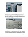

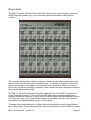


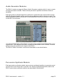

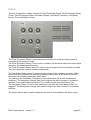

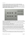
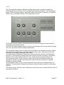
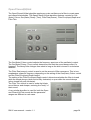


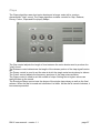
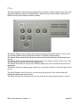
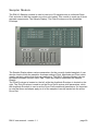
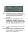

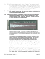
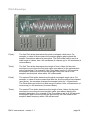

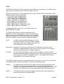

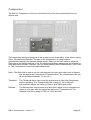

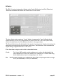
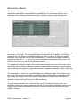
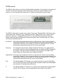

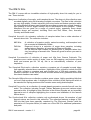
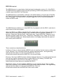
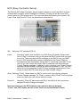
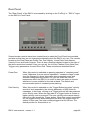
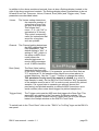

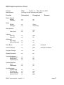


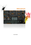

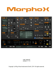
![ManyGuitar user manual [november 2005]](http://vs1.manualzilla.com/store/data/005861536_1-a0b937985b357a67600aa3c9a5e7e46a-150x150.png)