1
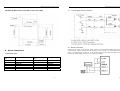
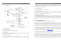
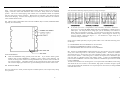
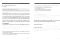
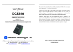
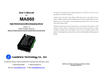
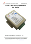
User’s Manual
For
DB810
Digital DC Servo Driver
Version 1.0
©2000 All Rights Reserved
Attention: Please read this manual carefully before using driver!
The content in this manual has been carefully prepared and is believed to be accurate, but no
responsibility is assumed for inaccuracies.
Leadshine reserves the right to make changes without further notice to any products herein to
improve reliability, function or design. Leadshine does not assume any liability arising out of the
application or use of any product or circuit described herein; neither does it convey any license
under its patent rights of others.
Leadshine’s general policy does not recommend the use of its products in life support or aircraft
applications wherein a failure or malfunction of the product may directly threaten life or injury.
According to Leadshine’s terms and conditions of sales, the user of Leadshine’s products in life
support or aircraft applications assumes all risks of such use and indemnifies Leadshine against all
damages.
©2000 by Leadshine Technology Company Limited.
All Rights Reserved
Floor 6, Block B, Yuehai Building, Nanhai Avenue, Shenzhen, China
T: (86)755-26471129, F: (86)755-26402718
URL: www.leadshine.com E-Mail: [email protected]
DB810 Digital DC Servo Driver V1.0
DB810 Digital DC Servo Driver V1.0
Table of Contents
Applications of this driver
Suitable for a wide range of equipment and instruments such as mini type engraving machines,
1. Introduction, Features and Applications ···································································2
2. Specifications and Operating Environment ······························································3
3. Driver Connectors ····································································································4
4. Servo Setup ···············································································································6
5. Tuning the Servo ······································································································7
6. Using Tips and Attention ···························································································10
Appendix: Limited Warrenty ·························································································13
jet-ink machines and etc.
It performs better in equipment expected with low noise, high precision
and high velocity.
2. Specifications and Operating Environment
Electric Specifications (Tj = 25℃)
1. Introduction, Features and Applications
DB810
Parameters
DB810 is a new digital DC servo driver developed with the advanced 21-century technology in the
Peak Output Current
Typical
Max.
Unit
0
-
20
Amps
VDC
+18
-
+80
world today. In position control, it’s easy for the end user to change the step driver to DB810
Logic signal current
6
12
20
mA
without change control system, because the input command is PUL/DIR signal, which is
Pulse input frequency
0
-
250
KHz
compatible with step driver command.
In velocity control, the position feedback of the encoder
effectively eliminate the “zero-speed drift” phenomenon when the analog servo is standstill.
Supply voltage
Min.
Isolation resistance
500
MΩ
Current provide to encoder
50
mA
In
the low power motion control applications, DB810 can be the same, or better than digital AC servo
Operating Environment and Parameters
systems in velocity, precision, noise, stability and other aspects, while the price is the same as step
driver, far lower than AC servo.
Cooling
Natural cooling or forced convection
Environment
Space
Avoid dust, oil frost and corrosive gas
Temperature
0°- 50℃
Features of this driver
18-80VDC, 0-20A, 20-400W
PID feedback servo drive
Storage Temp.
Feedback resolution X4 encoder line count
Weight
Humidity
40 - 95%RH
Vibration
5.9m/s Max
2
-20℃ - +65℃
Approx. 100 grams (3.53 oz)
Lock range +/- 128 count following error
Opto-isolated step and direction inputs
Small size
Over-current, short-circuit protection
2
3
DB810 Digital DC Servo Driver V1.0
DB810 Digital DC Servo Driver V1.0
Mechanical Dimensions (unit=mm, 1 inch = 25.4 mm)
3.2
3. Driver Connectors
3.3 Encoder Connection
Encoder power supply: if the encoder supply current is less than 50mA, DB810 can supply
voltage directly., connect E Gnd to encoder Ground, E+5V to encoder +5V, encoder phase A to
Phase A, encoder phase B to Phase B. If the encoder supply current is more than 50mA, use
an external +5VDC supply, and connect it as following diagram:
3.1 Definition of pins
Terminal
No.
1
2
3
4
5
6
Definition
POWER GROUND
+18 TO 80VDC
MOTOR+
MOTORERR/RES
E GND
Terminal
No.
7
8
9
10
11
12
Control Signal Connector Interface
Definition
E+5V
PHASE A
PHASE B
DIR
STEP
+5V
4
5
DB810 Digital DC Servo Driver V1.0
3.4
Typical Diagram
DB810 Digital DC Servo Driver V1.0
current rating must equal the maximum current you expect to run the motor at. When the
power supply lead is longer than 50 cm, connect between POWER GND and +18 TO 80VDC
with a 1000UF/100V electrolytic capacitor
4.1.3 Prepare Signal Source
Prepare a signal source with STEP and DIR signal.
4.1.4 Initial Setup DB810
Before going on, turn the current LIMIT trimpot a quarter to half of full scale. Turn the GAIN
trimpot fully off and turn the DAMP trimpot to a quarter of full scale. The trimpots are
single-turn, do not over-torque them with a screwdriver.
4.2 MOTOR CONNECTION
Make sure that the power is off and the STEP pulse source is set to zero pulse per second. Check
to see if the potentiometer setting are set according to the instructions. Press the motor so it
cannot jump off the bench. Motor will come back to command position quickly within shortest
time with mini overcharge, or no overcharge. Please refer to “use of PULS and DAMP” for the
test way.
5.
Tuning The Servo
Turn on the power supply, the FAULT light should turn off after 3 seconds.
5.1 If everything is correct you should hear the motor “singing”, this is normal. The motor is
dithering or bouncing between adjacent encoder counts. The integral term in a PID loop has
infinite DC gain over time and will amplify even the smallest position error. Because encoder
feedback can only occur on count edges, the loop is “blind” until it encounters an encoder count
edge. It then reverses the motor direction until another edge is found, then the process repeats.
If the motor jumps slightly and the FAULT light immediately turns back on, then either the motor
is wired backwards or the potentiometer misadjusted. Check the potentiometer settings, if they
seem right then switch the motor leads and try again. If it still doesn’t work after you followed
all of the previous steps, please contact us at [email protected].
4. Servo Setup
4.1 Before you start, you must fellow following steps:
4.1.1 Install Encoder
Firstly, you must have a suitable encoder mounted and properly aligned on the motor, assemble
the encoder according to factory manual.
4.1.2 Prepare Power Supply
Secondly, you must have a DC power supply suitable for the motor. Do not use a power
supply voltage more than 5 volts in excess of the motors rated voltage. The power supply
6
5.2 Now turn on your STEP pulse source and ramp the speed up to see if the motor runs.
should run clockwise with a logical “1” on the DIRECTION input.
It
5.3 The optimum way to tune the servo is to induce an impulse load on the motor while watching
an oscilloscope to see how the motor behaves in response, then adjusting the PID co-efficients for
optimal behavior. In all cases the motor must return to the command position, , what matters is
how it does it. The manner in which the motor returns to its command position is called damping.
At one extreme called overdamped response, the motor returns to position after a long, drawn out
7
DB810 Digital DC Servo Driver V1.0
delay. At the other extreme called underdamped response, the motor returns to its position too
rapidly, overshoots, returns and undershoots and so on until it finally settles at its command
position. This is also called ringring; when extreme, the over/undershoot builds in amplitude
until the motor enters violent oscillation. Between the two extremes is the optimal response
called critical damping. Here the motor rapidly returns to its position with little or no overshoot
in the minimal amount of time.
DB810 Digital DC Servo Driver V1.0
You can detective following response picture by seeing oscilloscope:
5.4 There are three potentiometer knob in the side of DB810, they are GAIN, DAMP and LIMIT
separately for current setting.
To see how your servo is compensated it is first necessary to induce a disturbance. The
easiest way is to switch the DIRECTION input while commanding a constant speed via the
STEP input. The abrupt direction change puts just the momentary load needed on the
motor while you watch how it response. If you are using an oscilloscope, use channel 1 on
the test point and channel 2 on the DIRECTION input. Set the trigger to “normal”, trigger
source to channel 2 and trigger edge to “+”. You should see a single sweep for every
clockwise change in direction.
Slowly increase STEP speed until you get a picture similar to one of the three following, and then
do the steps:
① OVERDAMPED: Decrease DAMPING or increase GAIN
② CRITICALLY DAMPED: Do nothing; you are here
③ UNDERDAMPED: Decrease GAIN or increase DAMPING
GAIN and DAMPING
GAIN and DAMPING setting generally track each other. If you increase GAIN (greater
stiffness), then increase DAMPING is needed as well to restore critical damping. Be
careful, increasing GAIN without increasing DAMPING may cause the motor to break out
into violent oscillation. The higher GAIN is set, the noisier the motor will be when stopped.
This is because higher gain causes more vigorous dithering between encoder counts at rest.
5.5
POSITION ERROR
5.6 If there are OVERDAMPING when tuning the servo, the response servo pulse command is
slowly, and it takes longer time to come back to command position. If there are OVERGAIN
when tuning the servo, the response servo pulse command is quickly, and stop only after several
times of servo vibration. If the tuning servo is normal, the response servo command is quickly,
and come back to command position with stability quickly. If there are OVERDDAMPING,
please decrease DAMPING or increase GAIN; if there are OVERGAIN, please decrease GAIN or
increase DAMPING.
To make it convenient for user to tuning, there is a test point inside of the DB810, as following:
You should set the servo control as: short distance, high speed, acceleration as high as possible,
motor runs back and forth, and then the servo response picture can be tested, so tuning DAMPING
and GAIN until correct.
The error between servo actual position and pulse command position, can be improved by tuning
servo parameter.
8
9
DB810 Digital DC Servo Driver V1.0
6.
Using Tips and Attention
6.1 Using Tips
6.1.1 The current LIMIT trimpot sets maximum current the motor is permitted to have. It is
adjustable from 0 amps to 20 amps. Normally the LIMIT trimpot is set to maximum (20 amps)
unless you want to limit motor torque to a lower value.
More speed and position is unaffected by the current LIMIT setting unless the torque demand due
to load exceeds this setting, then the motor position will fall behind the command position because
of insufficient torque.
6.1.2 Normally when the DB810 is first powered up, it will be necessary to push the momentary
switch to START for 5 seconds. This will clear the power-on reset condition and extinguish the
FAULT LED. The motor will then be enabled and the drive will begin to operate.
DB810 Digital DC Servo Driver V1.0
1).
The loop settings are severely under-damped and the motor breaks out into oscillation.
2).
Excessive motor load due to acceleration or workload.
3).
The speed command in excess of what the motor can deliver.
4).
The current LIMIT is set too low.
5).
The power supply current is insufficient for the demand.
6).
The motor is wired backwards, is broken or disconnected.
7).
Encoder failure.
6.1.2.2 Reversing Default Motor Direction
The DB810 will turn the motor in the CW direction when the DIRECTION input is “high” (logical
“1”, or +5VDC).
If at any time after that a condition occurs that causes the DB810 to “fault out”, such as not being
able to complete a step command, the ERR/RES terminal will go to “0”, signaling the computer an
error has occurred. This will require the operator to correct the problem that caused the fault and
then push the switch to “START” for 5 seconds to re-enable the DB810.
At anytime the operator can push the switch to the “STOP” position to immediately halt the
DB810 drive. Anytime the DB810 is in the “FAULT” state (FAULT LED lit), all switching
action stops and the motor freewheels and is unpowered. This will light the “FAULT” light.
6.1.2.1 Fault Indicator
The FAULT indicator is on while the drive is in power-on reset, the DISABLE input is held “low”
or if the protection circuit is tripped due to a fault condition.
and all internal counters are reset.
to try again.
All power MOSFETs are turned off
The FAULT condition lasts for 3 seconds, and then self-resets
If the protection circuit tripped it and the causes is not cleared, then it will
immediately re-enter the FAULT state again and repeat the cycle.
There are two conditions that will trip the protection circuit. One condition is if a short-circuit
If instead CCW is preferred, then:
1)
Reverse the motor “+” and “-“ leads (pin 3 with pin 4)
2)
Reverse the encoder “channel A” and “channel B” leads (pin 8 with pin 9)
6.1.2.3 ERR/RES
This terminal functions as an ERROR output and as a RESET input. Because this terminal
functions as both an input and an output, some detailed description is necessary.
When first testing the DB810, ERR/RES (term. 5) was connected to ENC+ (term. 7). It can be
left that way if it is not necessary to read the state of the ERROR output. Otherwise, the
following details are important.
The ERROR output is latched in the “ERROR” state (term. 5 = 0) by the power-on reset circuit in
the DB810. It will stay in this state indefinitely until it is cleared by applying +5V to this
terminal for at least 5 seconds.
The voltage on this terminal is +5VDC when the DB810 is functioning normally. The voltage on
this terminal goes to 0VDC whenever the FAULT indicator is lit. This output can be used to
signal your controller that an error has occurred.
occurs and current exceeds 20 amps.
The other condition is if the POSITION ERROR exceeds +/- 128 counts causing a break of the
servo-lock.
This condition can have several causes:
10
11
DB810 Digital DC Servo Driver V1.0
DB810 Digital DC Servo Driver V1.0
APPENDIX
TWELVE MONTH LIMITED WARRANTY
Leadshine Technology Co., Ltd. warrants its products against defects in materials and
workmanship for a period of 12 months from shipping date. During the warranty period,
Leadshine will either, at its option, repair or replace products which prove to be defective.
EXCLUSIONS
The above warranty shall not apply to defects resulting from: improper or inadequate handling by
customer; improper or inadequate customer wiring; unauthorized modification or misuse; or
operation outside of the electrical and/or environmental specifications for the product.
OBTAINING WARRANTY SERVICE
To obtain warranty service, a returned material authorization number (RMA) must be obtained
from customer service at e-mail: [email protected] before returning product for service.
Customer shall prepay shipping charges for products returned to Leadshine for warranty service,
and Leadshine shall pay for return of products to customer.
WARRANTY LIMITATIONS
The above circuit shows how to implement an external switch to clear an ERROR condition and
RESET the DB810, while still being able to read the state of the drive. It also includes an
optional FAULT LED circuit if a remote indication of the state of the DB810 is desired.
6.2 Attention
6.2.1 if the wire length longer than 50cm, you should connect a 1000UF capacitor between the
source terminal, pay attention that the polarity can not be reversed.
6.2.2 if the encoder power supply current is more than 50mA, please use an external +5VDC
supply, and between the two wires must be share ground, connection as: external ground with pin
6 E GND, and connect a 470Ω 1/4w resistor between pin 7 E+5V with pin 6 E GND.
12
Leadshine makes no other warranty, either expressed or implied, with respect to the product.
Leadshine specifically disclaims the implied warranties of merchantability and fitness for a
particular purpose. Some jurisdictions do not allow limitations on how long and implied warranty
lasts, so the above limitation or exclusion may not apply to you. However, any implied warranty of
merchantability or fitness is limited to the 12-month duration of this written warranty.
Shipping Failed Product
If your product should fail during the warranty period, e-mail customer service at
[email protected] to obtain a returned material authorization number (RMA) before returning
product for service. Please include a written description of the problem along with contact name
and address. Send failed product to distributor in your area or: Leadshine Technology Co., Ltd.
Floor 6, Block B, Yuehai Building, Nanhai Avenue, Shenzhen, China. Also enclose information
regarding the circumstances prior to product failure.
13