1
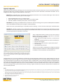
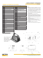
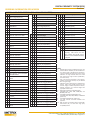
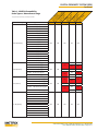
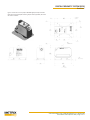
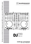
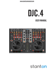
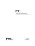
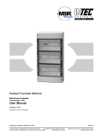
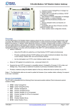
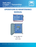
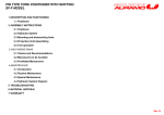
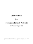
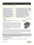
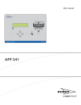
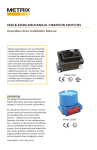
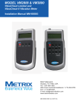
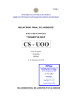
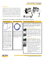
DIGITAL PROXIMITY SYSTEM (DPS)
Datasheet
OVERVIEW
The Metrix Digital Proximity System (DPS) combines the
performance of a fully API 670 compliant eddy-current
proximity measurement system with the flexibility of digital
configurability. For the first time, users can configure their
transducer system in the field using a custom field-generated
curve as well as factory pre-configured calibrations for a
variety of probe tip diameters, manufacturers, extension cable
lengths, target materials, and linear ranges. Refer to page two
of this datasheet for additional details on device configurability.
1180
The DPS consists of three elements: a Probe, Extension Cable, and Driver or Transmitter.
MX2030 PROBE SERIES
MX2031 EXTENSION CABLE
PROBE DRIVER OR TRANSMITTER
A probe or transmitter is available, depending on the
required signal output format: the MX2033 3-Wire Driver
and the MX2034 4-20 mA Transmitter. The models are fully
compatible with a large variety of probes and cables from
Metrix, BN4, and other manufacturers.
The MX2030 probe series
consist of 5mm and 8mm
tip diameter probes. The
models are available with
all standard thread sizes
and body configurations
required in API standard
670. Both probes offer a full
80 mil (2mm) range, and are
designed to offer full API
670 compliant performance
characteristics when used
with a matching MX2031
extension
cable
and
MX2033 driver or MX2034
transmitter. MX2030 probes
are fully interchangeable
with
Bently
Nevada
(BN)4, 3300 and 3300XL
5mm/8mm probes.
Available in a variety of
lengths and with optional
protective cable armor, the
MX2031 Extension Cable is
compatible with both Metrix
MX2030 5mm/8mm probes
and BN4 3300 and 3300XL
5mm/8mm probes.
MX2033 3-Wire Probe Driver
Dynamic Voltage Output (mV/μm or mV/mil)
MX2033 signal output is compatible with
industry-standard
continuous
vibration
monitoring systems (including the SETPOINT5
Machinery Protection System) and is the
format specified in API Standard 670. It uses
-24Vdc excitation and provides the output
signal in mV/μm, typically 7.87 mV/μm
(200mV/mil).
MX2034 4-20 mA Transmitter
Static Current Output (mA/mm or mA/mil)
MX2034 signal output provides thrust, radial
vibration, or shaft speed measurements
directly to PLCs, DCSs, SCADA systems, or
other instrumentation that accepts an ISA
Standard 4-20 mA signal, without the use of a
separate monitor system. The transmitter is a
+24 Vdc current loop powered device. It is userconfigurable to function as follows:
1. Radial vibration transmitter (4-20 mA signal is
proportional to pk-pk vibration amplitude)
2. Axial position transmitter (4-20 mA signal is
proportional to average probe gap)
3. Tachometer (4-20 mA signal is proportional
to shaft speed).
www.metrixvibration.com • [email protected] • 281.940.1802
Doc# 1087015 • REV P (October 2015) • Page 1 of 11
DIGITAL PROXIMITY SYSTEM (DPS)
Datasheet
FEATURES AND BENEFITS
Digitally Configurable
Metrix pioneered the patented technology used in the DPS which provides numerous performance and user-convenience benefits.
Developed in 2005 for our vibration transmitters, the technology has proven itself in thousands of installations worldwide. You can
configure the device using the included software in three ways:
- METHOD #1 - By selecting from a discrete list of pre-configured calibration curves to standard 4140 target material and the
following combinations of probe types and cable lengths:
•
•
•
Metrix MX2030 probe system, 5m and 9m lengths
Metrix / BN4 7200 series 5 and 8mm probe systems, 5m and 9m lengths
BN4 3300 / 3300XL 5 and 8mm probe systems, 5m and 9m lengths
- METHOD #2 - By specifying one additional factory-loaded curve1 at time of ordering, from any of the available options for MX2033
drivers and MX2034 transmitters (refer to pages 7 and 8 respectively).
NOTE: This memory will be left empty if not specified at time of ordering. It can be used in the field as per method #3 below.
- METHOD #3 - Generate a custom curve in the field2 by recording the gap voltage at 10 mil increments and entering it into the
software. A custom linearization table is then generated and loaded into the device. This method is particularly convenient when
the shaft target material composition is not known.
These configuration options provide the user with maximum
flexibility and accuracy in adapting a single driver or transmitter
device to the following parameters:
• Target material (including unknown or indeterminate
materials)
• Probe series and tip diameters from various manufacturers
• Extension cable lengths
• Position, thrust, radial vibration or speed measurement3
• Full scale range3
• Upscale/downscale direction3
The driver or transmitter is configurable via a USB port, protected
under the baseplate of the device. The DPS configuration software
is available as a free download at metrixvibration.com.
The DPS Configuration Software features a simple, intuitive user interface that
makes it easy to configure the signal conditioner in the field. Users can select
from a discrete list of factory pre-configured curves using drop-down boxes, or
generate a custom linearization curve in the field by entering gap voltages at
10mil increments.
Configured DPS units can easily be identified in the field using the DPS configuration software and our optional Metrix User Label Kit
P/N 100527 (see Accessories on page 11). The kit consists of specially shaped polycarbonate overlay labels and paper labels (Avery 6570).
The customized details are printed on an Avery 6570 label, and this is affixed under a clear rectangular window in the polycarbonate
overlay label, providing a weatherproof seal. Target material, probe type and series, system length, and output sensitivity can be recorded.
We provide user-configurable fields where you can record installation- and device-specific details such as date of last calibration,
instrument loop tag numbers, probe location (machine / bearing / angular orientation), and any other details useful to machinery and
instrumentation personnel.
NOTES:
1. One additional calibration curve can be stored in the device beyond the factory standard curves of method #1. This curve can be supplied by the factory per method #2,
or can be generated by the user in the field per method #3.
2. Custom curves assume standard supported probe types (MX2033/MX2034 option BB) and system lengths (MX2033/MX2034 option CC), and that mismatched systems
will not be used, such a 7200 cable with an MX2030 probe. Certain material types may limit total available linear range and other specifications. These can be quantified
when a material sample is provided to the factory.
3. These settings are applicable to MX2034 transmitters only.
4. Registered trademark(s) of Bently Nevada®.
5. Registered trademark(s) of Metrix®.
www.metrixvibration.com • [email protected] • 281.940.1802
Doc# 1087015 • REV P (October 2015) • Page 2 of 11
DIGITAL PROXIMITY SYSTEM (DPS)
Datasheet
FEATURES AND BENEFITS (Continued)
Full API 670 Compliance
The DPS was designed to fully comply with API 670
for linear range, interchangeability, standard probe
configurations, and all other details.
Reduced Spare Parts Inventory
The DPS reduces the requirements for spare parts by
allowing a single type of driver or transmitter to be
field-configured for a wide range of probe types, cable
lengths, and target materials.
Interchangeability
MX2030 probes and MX2031 extension cables are
fully interchangeable with BN1 3300 and 3300XL
5mm/8mm probe systems. Such compatibility
provides greater choice of suppliers without the need
to replace installed probes, cables, and drivers.
A user-generated label can be printed in the field with all device characteristics
as well as user-specific tagging and installation particulars.
Support for Older Probe Systems
Replacing a complete proximity transducer system can be not only expensive, but impractical when a machine must keep running and
probes/cables are buried inside. The ability to support older probe systems is becoming increasingly important as users push their
plant outage intervals to more and more years. Imagine being able to support not only a multitude of older probe systems, cable
lengths, and target materials, but to be able to do so with just a single driver or transmitter. MX2033 drivers and MX2034 transmitters
allow the user to change the configuration in the field for use with virtually any Metrix or BN4 proximity probe and cable (see ordering
information on page 7 and 8 for currently supported probe systems).
SPECIFICATIONS
The specifications on the following pages are based upon the following system components, target materials, gaps and temperatures2, 3:
•
•
•
•
•
•
MX2033 3-wire driver
MX2031 4.5m extension cable
MX2030 8mm probe with 0.5m cable
AISI 4140 steel target gapped at 50 mils (1.27 mm) from probe tip
Temp = 22° C
17 mARMS current loop noise floor
Specifications for MX2034 loop-powered transmitters assume the same probes, cables, target materials, temperatures, and current loop
noise floor as shown above.
Interchangeability and accuracy specifications assume the above Metrix products and target materials; they may differ when components
from other manufacturers are mixed with Metrix components4.
NOTES:
1. Registered trademark(s) of Bently Nevada®.
2. The American Petroleum Institute (API) Standard 670 defines two temperature ranges for proximity probe systems: Testing Range and Operating Range. Except as
otherwise noted, all specifications herein are for system performance at 22°C, in the middle of the API 670 Testing Range (0°C – 45°C).
3. Target materials other than AISI 4140 steel may restrict the transducer system’s linear range and other specifications. Consult the factory whenever using a non-4140
target to ensure the transducer system will be suitable for the intended measurement range and accuracy requirements.
4. A manufacturer’s interchangeability specifications are based on statistical variations against their own reference transducer system. Because the reference transducer
systems used by other manufacturers are not within the control of Metrix, interchangeability specifications for mixed systems cannot be guaranteed, but will generally
be about twice as large as when all transducer system components come from a single manufacturer. However, where known, these differences can be compensated
in the field using the transducer system’s configurability capabilities, allowing mixed system performance to meet or exceed that of a non-mixed system.
www.metrixvibration.com • [email protected] • 281.940.1802
Doc# 1087015 • REV P (October 2015) • Page 3 of 11
DIGITAL PROXIMITY SYSTEM (DPS)
SPECIFICATIONS (Continued)
Datasheet
ELECTRICAL
Channels:
Driver or transmitter accepts one probe and extension cable
Supported Probe Types: PROBE SERIES
TIP DIAMETER METRIX DATASHEET
MX2033 driver and MX2034 MX2030
5mm/8mm
1087015
Contact factory if you need
transmitters are compatible Metrix and BN1 3000
.190”/.300”
1004736
other probes or cables.
with the probes and
Metrix and BN1 7200
5mm/8mm
1009553
extension cables as shown.
BN1 3300 and 3300XL
5mm/8mm
N/A
BN1 RAM and NSv
5mm
N/A
Driver or Transmitter
MODEL
W/O BARRIERS W/ZENER BARRIERS W/GALVANIC BARRIERS
Excitation Voltage:
MX2033
(Reduced linear range will
17-30 Vdc
23-26 Vdc
20-30 Vdc
MX2034
occur when voltage at the
driver or transmitter terminal
is more positive than -19 Vdc)
Driver or Transmitter
Max Current
Consumption:
MODEL
MX2033
MX2034
Driver or Transmitter
Output Types:
MX2033- Terminal: 7.87 mV/mm (200 mV/mil) (instantaneous gap)
MX2034 -
IMAX
10 mA
23 mA
Radial vibration
Axial position
RPM
TERMINAL
Proportional 4-20 mA (mils pk-pk, mm)
4-20 mA proportional to position (mils)
4-20 mA proportional to speed
BNC
7.87 mV/mm (200 mV/mil)
(instantaneous gap)
Field Wiring Gauge:
Recommended: 0.8 mm2 (18 AWG)
Allowed: 0.2 to 1.3 mm2 (16 to 24 AWG)
Field Wiring Type:
MX2033: 3-conductor shielded cable
MX2034: 2-conductor shielded cable (4-20 mA)
RG-58 A/U coax cable (BNC connector)
Max. Field Wiring Length:MX2033: 1500 m (4920 ft) between driver and monitor3
MX2034: 4-20 mA: 5000 m (16,400 ft) between transmitter and monitor3
Min. Target Size:
15.2 mm (0.6 in) diameter (assuming flat surface)
Min. Shaft Diameter:
Absolute: 50.8 mm (2.0 in)
Recommended: 76.2 mm (3.0 in)
Linear Range:
PROBE TYPE
RANGE
MX2030 (5mm/8mm)
BN 3300 and 3300XL
(5mm/8mm)
Metrix and BN1 7200
(5mm/8mm)
Metrix and BN1 3000 (.190 in)
Metrix and BN1 3000 (.300 in)
BN1 NSv and RAM
Suggested Probe Gap:
2mm or 80 mils*
* Range starts at approx. 10 mils gap (-1V)
** Range starts at approx. 20 mils gap (-1V)
1mm or 40 mils*
1.25mm or 50 mils**
1.5mm or 60 mils*
-9V
NOTES:
1. Registered trademark(s) of Bently Nevada®.
2. Length limit is imposed by distributed cable resistance and corresponding voltage drop at maximum current output. Assumes 18 AWG 2-conductor cable with
resistance of 20 Ω/km, 24 VDC supply voltage, 250 Ω load resistance, no I.S. barriers. Consult the manual for further details.
3. Length limit is imposed by distributed cable capacitance and corresponding frequency response roll-off. Assumes standard 18AWG 3-conductor cable with
capacitance of 290 pF/m, no I.S. barriers. Total cable capacitance in excess of 450 nF will limit frequency response at monitor to less than published 8-kHz
specification. Consult the manual (Metrix Document 1093672) for further details.
www.metrixvibration.com • [email protected] • 281.940.1802
Doc# 1087015 • REV P (October 2015) • Page 4 of 11
DIGITAL PROXIMITY SYSTEM (DPS)
SPECIFICATIONS (Continued)
Frequency Response:
MODEL
MX2033
MX2034
Datasheet
± 3dB RESPONSE
0-8 kHz
Vibration Configuration (option FF=01-49)
4-20 mA: 5 Hz - 5 kHz
Buffered: 0 - 5 kHz
Position Configuration (Option FF= 0-98)
4-20 mA: 0 - 1.2 Hz
Buffered: 0 - 5 kHz
4 - 20 mA Update Rate: 150 ms (applies to MX2034 only)
Incremental Scale
Factor (ISF)1-4 and
Deviation from Best-Fit
Straight Line (DSL):
PROBE TYPE
MX2030 (5mm/8mm)
BN5 3300 and 3300XL (5mm/8mm)
Metrix and BN5 7200 (5mm/8mm)
Metrix and BN5 3000 (.190”)
Metrix and BN5 3000 (.300”)
BN5 NSv and RAM
Accuracy:
0.3% typical, 1% max.
ISF (Incremental Scale Factor)
DSL (Deviation from Straight Line)
7.87 mV/μm ± 5% (200 mV/mil) ± 0.025 mm (± 1 mil)
7.87 mV/μm ± 10% (200 mV/mil) ± 0.06 mm (± 2.4 mil)
7.87 mV/μm ± 20% (200 mV/mil)
± 0.1 mm (± 3.9 mil)
7.87 mV/μm ± 20% (200 mV/mil)
7.87 mV/μm ± 20% (200 mV/mil) ± 0.06 mm (± 2.4 mil)
MECHANICAL
Probe Tip Material:
Polyphenylene Sulfide (PPS)
Probe Case Material:
FWD-mount probe: AISI 304 stainless
steel
REV-mount probe: AISI 303 stainless
steel
Probe Cable Type:
75Ω coaxial, Tefzel® 750 insulation
(ethylene – tetrafluoroethylene ETFE)
Extension Cable Type:
75Ω coaxial, Tefzel® 750 insulation
(ethylene – tetrafluoroethylene ETFE)
Driver Case Material:
PBT thermoplastic polymer blend
(contains PBT, carbon fiber, and glass
beads)
Optional Flexible Armor: AISI 304 stainless steel (armor)
AISI 303 stainless steel (armor ferrule)
Tensile Strength:
Probe body to probe cable: 245N
(55 lb)
Cable to Connector: 245N (55 lb)
Connector Material:
Gold-plated brass
Connector Gender:
Probe: Male
Extension Cable: Female and Male
Driver or Transmitter: Female
Connector Type:
Miniature knurled
Connector Torque:
Maximum: 0.565 N-m (5 in-lb)
Recommended: finger tight
Min. Cable Bend Radius: Without Armor: 25.4 mm (1.0 in)
With Armor: 25.4 mm (1.0 in)
NOTE: An ETFE outer jacket is not included on Metrix extension cable and probe
armor as it tends to degrade, rather than enhance, moisture and corrosion
resistance.
Probe Case Torque:
PROBE TYPE
8mm FWD mount
5mm FWD mount
8mm REV mount
MAX. RATED
33.9 N-m (300 in-lb)
7.3 N-m (65 in-lb)
22.6 N-m (200 in-lb)
RECOMMENDED
11.3N-m (100 in-lb)
5.1 N-m (45 in-lb)
7.5 N-m (66 in-lb)
ENVIRONMENTAL
Operating and Storage Temperature:
Probe: -51°C to +177°C (-60°F to +350 °F)
Extension Cable: -51°C to +177°C (-60°F to +350°F)
Driver or Transmitter: -40°C to +85°C (-40°F to +185°F)
Relative Humidity: 95%, non-condensing
Probe tip-to-case Pressure Rating: 13.6 bar (200 psi )
Patents:Digital performance curve technology in driver and transmitter:
US patent number 7768258.
RECOMMENDED BARRIERS
Passive Zener: Active Galvanic:
MX2033: MTL 7796- (or equivalent)
MX2034: MTL 7787+ (or equivalent)
MX2033: MTL 5531, P&F KFD2-VR4-Ex1.26, or equivalent
MX2034: MTL 5541, P&F KFD2-STC4-Ex1, or equivalent
NOTES:
1. Values shown for 5m systems. For 9m systems, add 1.5%.
2. Includes interchangeability errors when measured in
increments of 0.25 mm (10 mils) over the linear range
between 0°C and 45°C (API Testing Range).
3. ISF shown assumes mV-type output and is valid for MX2033
and BNC connector on MX2034.
4. Above ISF values for MX2034 transmitter pertain only to
the BNC connector. The ISF for the transmitter’s 4-20mA
proportional output is applicable only when configured for
position measurements (EE=02). ISF is not applicable to
the 4-20mA output on transmitters configured for vibration
measurements (EE=01).
5. Registered trademark(s) of Bently Nevada®.
www.metrixvibration.com • [email protected] • 281.940.1802
Doc# 1087015 • REV P (October 2015) • Page 5 of 11
DIGITAL PROXIMITY SYSTEM (DPS)
Datasheet
SPECIFICATIONS (continued)
HAZARDOUS AREA APPROVALS
AREA
PROBE/CABLE
DRIVER
North America
Class I, Div 1, Grps A,B,C,D
-40°C to +177°C
Intrinsically Safe and Non-Incendive
Class I, Div 1, Grps A,B,C,D, T4
-40°C ≤Ta≤ +85°C
Intrinsically Safe (MX2034)
Class I, Div 2, Grps A,B,C,D, T4
-40°C ≤Ta≤ +85°C
Non-Incendive (MX2034)
International
ATEX/IECEX
II 1G Ex ia IIC T3 Ga
-40°C ≤Ta≤ +177°C
Intrinsically Safe
II 1G Ex ia IIC T4 Ga
-40°C ≤Ta≤ +85°C
Intrinsically Safe
II 3G Ex nA IIC T3 Gc
-40°C ≤Ta≤ +177°C
Non-Incendive
II 3G Ex nA IIC T4 Gc
-40°C ≤Ta≤ +85°C
Non-Incendive
WEIGHT AND DIMENSIONS
Dimensions:
MX2033 Driver: See Fig 1, page 7
MX2034 Transmitter: See Fig 2, page 10
Weight:
Probe: 298 g (10.5 oz)
Extension cable: - 33 g/m (0.35 oz/ft) without armor
- 98 g/m 1.05 oz/ft) with armor
MX2033 Driver: 247 g (8.7 oz)
MX2034 Transmitter: 247 g (8.7 oz)
ACCESSORIES
Mounting Options for MX2033 and MX2034:
- 35mm DIN rail (standard)
- 4-hole flat base with 2” x 2” and 2.5” x 2.75” hole patterns (requires optional adapter P/N 9647)
www.metrixvibration.com • [email protected] • 281.940.1802
Doc# 1087015 • REV P (October 2015) • Page 6 of 11
DIGITAL PROXIMITY SYSTEM (DPS)
ORDERING INFORMATION FOR MX2033
Datasheet
MX2033-AA-BB-CC-DD (DPS 3-WIRE PROBE DRIVER)
A A Material Calibration1
B B Probe Type
0 0
Not configured (future)
0 1
AISI-SAE 4140 CrMo Steel
0 2
17-4 Stainless Steel2
0 3
Incoloy 901
0 4
K500 Monel
0 5
Inconel 625
0 6
410 Stainless Steel
0 7
316 Stainless Steel
0 8
AISI-SAE 1045 Plain Carbon Steel
0 9
416 Stainless Steel
1 0
42CrMo4
1 1
18CrNiMo7-6
1 2
31CrMoV9
1 3
ST52-3
1 4
F6NM
1 5
7075-T6 Aluminum
1 6
Aluminized Steel
1 7
AISI-SAE 1018 Steel
1 8
15CrNi6
1 9
Tungsten Carbide
2 0
304 Stainless Steel
2 1
AISI-SAE 4320 Steel
9 9
Other4
1
0 0
Not configured (future)
0 1
5mm & 8mm – MX2030/BN3
3300/BN3 3300XL
0 2
5mm & 8mm – Metrix 7200/BN3
7200
0 3
0.190” – Metrix 3000/BN3 3000
0 4
0.300” – Metrix 3000/BN3 3000
0 5
BN3 NSv and RAM
9 9
Other
C C
System Length
0 0
Not configured (future)
0 5
5 meter5
0 7
7 meter6
0 9
9 meter7
1 5
15 feet8
2 0
20 feet8
9 9
Other
NOTES:
1. AISI-SAE 4140 chromium molybdenum steel is the
standard default calibration per API 670. If no material
type is specified at time of ordering, a factory-standard
AISI 4140 target will be used. Calibration to target
materials other than 4140 may restrict linear range and
other specifications. Consult the factory.
2. Due to the electrical properties of this material,
vibration measurement accuracy may be affected when
using this target.
3. Registered trademark(s) of Bently Nevada®.
4. Calibration to other material types is available upon
request. Metrix will normally request that the customer
supply a suitable sample of the material, allowing a
machined target with appropriate surface finish to be
produced.
5. Compatible with BN3 7200, 3300, 3300XL, NSv, and
Metrix MX2030 probes only.
6. Compatible with BN3 NSv and RAM probes only.
7. Compatible with BN3 7200, 3300, 3300XL, and MX2030
probes only.
8. Compatible with 3000 series probes only.
9. ETL, ATEX, Intertek and IECEx hazardous area approvals.
D D Approvals
0 0
None
0 5
Multiple Approvals9
9 9
Other
Figure 1: Dimensions in inches
[mm] for the MX2033 3-wire
digital proximity driver
Note: optional 4-hole baseplate mounting adapter shown
(P/N 9647). 35mm din rail
mount is standard.
www.metrixvibration.com • [email protected] • 281.940.1802
Doc# 1087015 • REV P (October 2015) • Page 7 of 11
DIGITAL PROXIMITY SYSTEM (DPS)
Datasheet
ORDERING INFORMATION FOR MX2034
MX2034-AA-BB-CC-DD-EE-FFF-GG (DPS 4-20 MA TRANSMITTER)
A A Material Calibration1
D D Approvals
F
F
F
Full Scale Range10 (Continued)
0
0 Not configured (future)
0
0 None
2
0
2
2000 RPM (Speed)
0
1 AISI-SAE 4140 CrMo Steel1
0
5 Multiple Approvals9
3
6
2
3600 RPM (Speed)
0
2 17-4 Stainless Steel
9
9 Other
4
0
2
4000 RPM (Speed)
0
3 Incoloy 901
E
E
5
0
2
5000 RPM (Speed)
0
4 K500 Monel
0
0 Not configured (future)
6
0
2
6000 RPM (Speed)
0
5 Inconel 625
0
1 Vibration
7
5
2
7500 RPM (Speed)
0
6 410 Stainless Steel
0
2 Position
1
0
3
10000 RPM (Speed)
0
7 316 Stainless Steel
0
3 Speed
1
5
3
15000 RPM (Speed)
0
8 AISI-SAE 1045 Carbon Steel
F
F
F
5
0
3
50000 RPM (Speed)
0
9 416 Stainless Steel
0
0
0 Not configured (future)
6
0
3
60000 RPM (Speed)
1
0 42CrMo4
0
0
1 3 mils, pk-pk (Vibration)
7
5
3
75000 RPM (Speed)
1
1 18CrNiMo7-6
0
0
2 4 mils, pk-pk (Vibration)
1
0
4
100000 RPM (Speed)
1
2 31CrMoV9
0
0
3 5 mils, pk-pk (Vibration)
0
9
9
Other
1
3 ST52-3
0
0
4 6 mils, pk-pk (Vibration)
G
G Pulses / Revolution
1
4 F6NM
0
0
5 10 mils, pk-pk (Vibration)
0
0
N/A (for vibration or position)
1
5 7075-T6 Aluminum
0
0
6 15 mils, pk-pk (Vibration)
X
X
1
6 Aluminized Steel
0
0
7 20 mils, pk-pk (Vibration)
1
7 AISI-SAE 1018 Steel
0
0
8 30 mils, pk-pk (Vibration)
1
8 15CrNi6
0
0
9 40 mils, pk-pk (Vibration)
XX= number of pulses per revolution
(keyways), valid entries are two
digit numbers from 01-99, with a
maximum value of RPM x # Keyways
≤ 190,000
1
9 Tungsten Carbide
0
2
1 100 µm, pk-pk (Vibration)
2
0 304 Stainless Steel
0
2
2 150 µm, pk-pk (Vibration)
2
1 AISI-SAE 4320 Steel
0
2
3 200 µm, pk-pk (Vibration)
2
Measurements
Full Scale Range
10
9
9 Other
0
2
4 250 µm, pk-pk (Vibration)
B
B Probe Type
0
2
5 300 µm, pk-pk (Vibration)
0
0 Not configured (future)
0
2
6 400 µm, pk-pk (Vibration)
0
1 5mm & 8mm – Metrix 2030/BN
3300/BN3300XL
0
2
7 500 µm, pk-pk (Vibration)
0
2
8 750 µm, pk-pk (Vibration)
0
2
9 1000 µm, pk-pk (Vibration)
0
5
0 30-70 mils, avg gap (Position)
0
5
1 20-80 mils, avg gap (Position)
0
5
2 10-90 mils, avg gap (Position)
0
5
3 10-50 mils, avg gap (Position)
0
5
4 20-70 mils, avg gap (Position)
0
5
5 10-60 mils, avg gap (Position)
0
7
0 750-1750 µm, avg gap (Position)
0
7
1 500-2000 µm, avg gap (Position)
0
7
2 250-2250 µm, avg gap (Position)
0
7
3 250-1250 µm, avg gap (Position)
0
7
4 500-1750 µm, avg gap (Position)
0
7
5
3
4
0
2 5mm & 8mm – Metrix 7200/BN4
7200
0
3 0.190” – Metrix 3000/BN4 3000
0
4 0.300” – Metrix 3000/BN4 3000
0
5 BN4 NSv and RAM
9
9 Other
C
C System Length
0
0 Not configured (future)
0
5 5 meter5
0
7 7 meter6
0
9 9 meter7
1
5 15 feet8
2
0 20 feet8
9
9 Other
250-1500 µm, avg gap (Position)
NOTES:
1. AISI-SAE 4140 chromium molybdenum steel is the
standard default calibration per API Standard 670.
If no material type is specified at time of ordering,
a factory-standard AISI 4140 target will be used.
Calibration to target materials other than 4140
may restrict linear range and other specifications;
consult the factory.
2. Due to the electrical properties of this material,
vibration measurement accuracy may be affected
when using this target.
3. Calibration to other material types is available upon
request. Metrix will normally request that the
customer supply a suitable sample of the material,
allowing production of a machined target with
appropriate surface finish.
4. Registered trademark(s) of Bently Nevada®.
5. Compatible with 7200, 3300, 3300XL,NSv, and
MX2030 probes only.
6. Compatible with NSv and RAM probes only.
7. Compatible with 7200, 3300, 3300XL, and MX2030
probes only.
8. Compatible with 3000 series probes only.
9. ETL, ATEX, Intertek and IECEx hazardous area
approvals.
10. Refer to Table 1 on following page for probe (BB),
measurement (EE), and full scale range (FFF)
compatibility details.
www.metrixvibration.com • [email protected] • 281.940.1802
Doc# 1087015 • REV P (October 2015) • Page 8 of 11
DIGITAL PROXIMITY SYSTEM (DPS)
DIGITAL PROXIMITY SYSTEM
(DPS)
Datasheet
* Registered trademark(s) of Bently Nevada®.
Measurement Type
EE=01 (Vibration)
EE=02 (Position)
EE=02 (Position)
EE = 03 (Speed)
Full Scale Range
FFF=001 3 mils, pk-pk
FFF=002 4 mils, pk-pk
FFF=003 5 mils, pk-pk
FFF=004 6 mils, pk-pk
FFF=005 10 mils, pk-pk
FFF=006 15 mils, pk-pk
FFF=007 20 mils, pk-pk
FFF=008 30 mils, pk-pk
FFF=009 40 mils, pk-pk
FFF=021 100 µm, pk-pk
FFF=022 150 µm, pk-pk
FFF=023 200 µm, pk-pk
FFF=024 250 µm, pk-pk
FFF=025 300 µm, pk-pk
FFF=026 400 µm, pk-pk
FFF=027 500 µm, pk-pk
FFF=028 750 µm, pk-pk
FFF=029 1000 µm, pk-pk
FFF=050
30-70 mils, avg gap
FFF=051
FFF=052
20-80 mils, avg gap
10-90 mils, avg gap
FFF=053
10-50 mils, avg gap
FFF=054
20-70 mils, avg gap
FFF=055
10-60 mils, avg gap
FFF=070
750-1750 µm, avg gap
FFF=071
FFF=072
500-2000 µm, avg gap
250-2250 µm, avg gap
FFF=073
250-1250 µm, avg gap
FFF=074
500-1750 µm, avg gap
FFF=075
250-1500 µm, avg gap
FFF=202
FFF=362
FFF=402
FFF=502
FFF=602
FFF=752
FFF=103
FFF=153
FFF=503
FFF=603
FFF=753
FFF=104
2000 RPM
3600 RPM
4000 RPM
5000 RPM
6000 RPM
7500 RPM
10000 RPM
15000 RPM
50000 RPM
60000 RPM
75000 RPM
100000 RPM
Datasheet
5
M m
BN etr m &
* ix 8m
33 20 m
00 30
/ /
5m BN
M m *3
BN etr & 30
* ix 8m 0X
72 72 m L
00 00
/
0
M .19
BN etr 0”
* ix
30 30
00 00
/
0.
M 30
BN etr 0”
* ix
30 30
00 00
/
NS
BN v*
* &
RA
M
Table 1 - MX2034 Compatibility
Probe Type vs. Measurement Range
BB=01
BB=02
BB=03
BB=04
BB=05
YES
YES
YES
YES
YES
YES
YES
NO
NO
YES
YES
YES
NO
YES
YES
NO
YES
YES
YES
NO
YES
NO
YES
YES
YES
NO
YES
YES
YES
NO
NO
YES
YES
YES
NO
YES
YES
YES
YES
www.metrixvibration.com • [email protected] • 281.940.1802
Doc# 1087015 • REV P (October 2015) • Page 9 of 11
DIGITAL PROXIMITY SYSTEM (DPS)
Datasheet
Figure 2: Dimensions in inches [mm] for MX2034 digital proximity transmitter
Note: optional 4-hole baseplate mounting adapter shown (P/N 9647). 35mm din
rail mount is standard.
www.metrixvibration.com • [email protected] • 281.940.1802
Doc# 1087015 • REV P (October 2015) • Page 10 of 11
DIGITAL PROXIMITY SYSTEM (DPS)
ACCESSORIES
Datasheet
DPS User Label Kit for up to 16 devices (P/N 100527)
DIN to 4-Hole Flat Base Mounting Adapter (P/N 9647)
Each MX2033 driver and MX2034 transmitter comes with the four
factory-applied labels summarized below. The DPS User Label Kit
allows the Left Sidewall Label to be replaced with a customized
label containing installation-specific data, as depicted on page 3
of this datasheet. The User Label Kit contains enough materials
for labeling up to 16 signal conditioners as follows:
This adapter allows the 35mm DIN rail clip on MX2033 driver,
and MX2034 transmitters to be compatible with a 4-hole flat
base mounting method. The adapter has industry-standard hole
patterns for both a 2” x 2” square and a 2.75” x 2.5” rectangle.
The 2” x 2” pattern matches the holes on Metrix 5533 drivers and
BN* 3300, 7200, and 3000 series Proximitor* devices. The 2.75” x
2.5” pattern matches the holes on Metrix 5465/5488 transmitters
and BN* 990/991 transmitters. Material is 19 gauge mild steel
(ASTM A366 or equal) with gold chromate zinc plating.
•
16 specially-shaped
polycarbonate adhesive
labels with a clear
rectangular window and
the Metrix logo.
• A sheet of 32 standard
1.75” W x 1.25” H labels
(Avery 6570).
Using the Metrix DPS Configuration Software, the desired
information is printed directly onto the Avery 6570 sheet using
any Windows-compatible inkjet or laser printer. The printed
Avery label is removed from the sheet, placed behind the window
on the polycarbonate label, and both are then affixed to the left
sidewall of the DPS signal conditioner. The polycarbonate label
uses the same finish as all other factory-applied labels, providing
protection from the elements and giving a clean, durable, and
professional finish.
NOTE: The User Label Kit must be ordered separately and is not automatically
included with driver or transmitter.
Of the four labels affixed to each DPS signal conditioner, only
the Left Sidewall Label is intended for customization and field
replacement. The others are designed to remain permanently
affixed to the device during its life and contain information that
does not change with device configuration.
1. Left Sidewall Label (Configured Devices)
All devices ordered in a programmed state will have this label a
fixed. The label will reflect the as-ordered configuration data.
MANUALS AND SOFTWARE
2. Right Sidewall Label
This is a factory-applied permanent label with the serial number,
date of manufacture, model number and all approvals data.
The most recent versions of the Metrix DPS Configuration
Software and the DPS user manual can be downloaded from the
Metrix website, www.metrixvibration.com.
3. Front Label
This is a factory-applied permanent label that indicates the
connector for the probe and extension cable.
4. Top Label
This is a factory-applied permanent label that indicates the
wiring terminals, model number, and (MX2034 only) BNC
connection details.
NOTE: Manuals are published electronically in Adobe® PDF format and may
be printed and freely distributed. Adobe Reader is required and can be
downloaded free from www.adobe.com.
* Registered trademark(s) of Bently Nevada®.
www.metrixvibration.com • [email protected] • 281.940.1802
Doc# 1087015 • REV P (October 2015) • Page 11 of 11