1
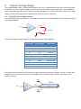
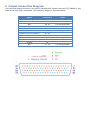
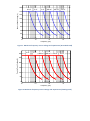
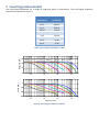
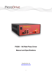
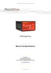
PD32 - 32 Channel Piezo Driver Manual and Specifications PiezoDrive Pty. Ltd. www.piezodrive.com Contents 1 Introduction ........................................................................................................................................... 3 2 Warnings / Notes ................................................................................................................................... 3 3 Specifications ......................................................................................................................................... 4 4 Output Voltage Range ........................................................................................................................... 5 4.1 Ground load configurations ........................................................................................................... 5 4.2 Floating load configuration ............................................................................................................ 6 5 Input Connection Diagram .................................................................................................................... 6 6 Output Connection Diagram ................................................................................................................. 7 7 Output Current ...................................................................................................................................... 8 8 Power Bandwidth .................................................................................................................................. 8 9 Small Signal Bandwidth ....................................................................................................................... 10 10 Overload Protection ......................................................................................................................... 11 11 Enclosure .......................................................................................................................................... 11 12 Signal Adaptors ................................................................................................................................ 11 13 Waranty ........................................................................................................................................... 11 1 Introduction The PD32 is a high-bandwidth, low-noise linear amplifier for driving up to 32 piezoelectric actuators. The voltage range is configurable from +50V to +/-140V and includes asymmetric voltage ranges such as -20V to +120V. The PD32 works seamlessly with common multi-channel DAC cards and provides exceptional ease of use and compatibility with programming tools such as LabView and Simulink. The compact size and 19-inch rack compatibility provides a comprehensive off-the-shelf solution for driving hundreds or thousands of piezoelectric actuators. The PD32 is designed for demanding applications such as Adaptive Optics, Acoustic Beam Forming, Materials Testing, Astronomy, Ultrasonics, and Vibration Control. With an output current of 150mA per channel, a large array of piezoelectric actuators can be driven simultaneously at high frequencies. Positive and negative high-voltage bias outputs are also included for compatibility with piezoelectric bender actuators. Compatible Actuators Stack Actuators 60V, 100V, 120V, 150V Plates and Tubes Two Wire Benders Three Wire Benders up to +/-140V up to +/-140V Up to 140V, or +/-75V Each channel is individually protected against short circuit and thermal overload. Status indicators on the front panel provide individual monitoring of all channels. A digital status signal and external shutdown command is also accessible from the input connector to allow remote monitoring and control. The input and output connectors are industry standard 37 Pin D-Sub connectors which are straight-forward to assemble. Adaptors are available for industry standard 32 Channel DAC cards. 2 Warnings / Notes This device produces hazardous potentials and should be used by suitably qualified personnel under the supervision of an observer with appropriate first-aid training. Do not operate the device when there are exposed conductors. 3 Specifications Unipolar Output Output Voltage +50V to +140V Bipolar Output +/-50V to +/-140V Peak Current 150 mA per channel 75 mA per channel RMS Current 106 mA per channel 53 mA per channel Power Bandwidth 50 kHz (120 Vpp) 50 kHz (240 Vpp) Signal Bandwidth 120 kHz 120 kHz Slew Rate 19 V/us 38 V/us Gain 15 V/V Input Impedance 53 kOhm Input Offset ±5 mV Load Unlimited Output Noise 200 uV RMS (1uF Load) 20 V/V 6.25 kOhm ±5 mV Unlimited 300 uV RMS (1uF Load) Protection Short-circuit and thermal overload Inputs 32 Analog inputs, shutdown command Outputs 32 HV Analog outputs, overload monitor Connectors Industry standard DB-37 (input) and DD-78 (output) Mechanical Environment -40 to 60C (-40 to 140F) Non-condensing humidity Dimensions 212 x 304.8 x 88 mm Weight 2 kg 4 Output Voltage Range The output voltage range is configurable between +50V and +/-140V and the load can be either grounded or floating. For peak-to-peak voltages less than 140V, the grounded load configuration is recommended since this provides greater current. The floating load configuration is required for the +/-100V and +/-140V ranges. The desired configuration should be specified at the time of ordering. 4.1 Ground load configurations In the grounded load configurations, the actuator connections are illustrated below. The negative output is internally grounded. In1 Out1+ 15 + Piezo 1 Out1- The desired output voltage range can be selected from the following table. Min Voltage Max Voltage Order Code 0 0 0 0 0 +140 +120 +100 +70 +50 PD32-140 PD32-120 PD32-100 PD32-70 PD32-50 -20 -20 +120 +100 PD32-20/120 PD32-20/100 -72 -48 +72 +48 PD32-72/72 PD32-48/48 Three wire bender actuators can be driven using the following connection diagram. The HV+ and HV- bias voltages are the minimum and maximum voltages listed in the table above and are accessible on the output connector. HV+ Piezo 1 In1 15 Out1+ HV- 4.2 Floating load configuration The floating load configuration is useful for achieving higher peak-to-peak voltage swings. The connection diagram is illustrated below. Do not connect either of these signals to ground, for example, an oscilloscope probe. Out1+ In1 + 20 Piezo 1 Out1- The desired output voltage range can be selected from the following table. Min Voltage Max Voltage Order Code -140 -100 +140 +100 PD32-140/140 PD32-100/100 5 Input Connection Diagram The front panel input connector is an industry standard DB37 Female Connector (TE 1658612-1). Any Male DB-37 cable plug is compatible. The connection diagram is illustrated below. Signals Input Connector Notes Analog Inputs 1 to 32 Ground Non Connected Digital disable command Overload indicator Pins 1 to 32 33, 34 35 Pin 36 Pin 37 +/- 10V max 3.3V or 5V logic 5V logic 6 Output Connection Diagram The front panel output connector is an industry standard DB37 Female Connector (TE 5748483-5). Any Male DD-78 cable plug is compatible. The connection diagram is illustrated below. Signals Outputs 1 to 16 (positive) Ground HV+ Outputs 1 to 16 (negative) Ground HVOutputs 17 to 32 (positive) Ground HV+ Outputs 17 to 32 (negative) Ground HV- Connector 1 1 - 16 17, 20 18, 19 21 - 36 37 38, 39 40 - 55 56, 59 57, 58 60 - 75 76 77, 78 Notes For driving benders For driving benders For driving benders For driving benders 7 Output Current The peak output current is 150 mA per channel in the grounded load configuration or 75 mA per channel in the floating load configuration. The maximum RMS current is 106 mA in the grounded configuration and 53 mA in the floating load configuration. The maximum simultaneous output current from all channels is 1.5 A. 8 Power Bandwidth The nominal slew-rate of the PD32 in the grounded load configuration is 19 V/us. Therefore, the unloaded maximum frequency sine-wave is 𝑓𝑚𝑎𝑥 = 19 × 106 . 𝜋𝑉𝐿(𝑝−𝑝) That is, the power bandwidth for a 120 Vp-p sine-wave is 50 kHz. In the floating load configuration, the slew-rate is doubled to 38 V/us, therefore, the power bandwidth for a 240 Vp-p sine-wave is 50 kHz With a capacitive load, the power bandwidth is limited by the output current. The maximum frequency sine wave is 𝑓𝑝𝑤𝑟 = 𝐼 𝑝𝑘 𝜋𝑉𝐿(𝑝−𝑝) 𝐶𝐿 where 𝐼𝑝𝑘 is the peak current limit, 𝑉𝐿(𝑝−𝑝) is the peak-to-peak output voltage, and 𝐶𝐿 is the effective load capacitance. The power bandwidth versus load capacitance is listed below. Load Cap. 10 nF 30 nF 100 nF 300 nF 1 uF 3 uF 10 uF 30 uF Peak to Peak Voltage (Grounded) 50 100 140 95 kHz 47 kHz 34 kHz 31 kHz 15 kHz 11 kHz 9.5 kHz 4.7 kHz 3.4 kHz 3.1 kHz 1.5 kHz 1.1 kHz 950 Hz 470 Hz 340 Hz 310 Hz 150 Hz 114 Hz 96 Hz 48 Hz 34 Hz 32 Hz 16 Hz 11 Hz Load Cap. 10 nF 30 nF 100 nF 300 nF 1 uF 3 uF 10 uF 30 uF Peak to Peak Voltage (Floating) 100 200 280 23 kHz 11 kHz 8.5 kHz 7.9 kHz 3.9 kHz 2.8 kHz 2.3 kHz 1.1 kHz 850 Hz 790 Hz 390 Hz 284 Hz 230 Hz 119 Hz 85 Hz 80 Hz 40 Hz 28 Hz 24 Hz 12 Hz 9 Hz 8 Hz 4 Hz 3 Hz Table 1. Power Bandwidth versus Load Capacitance (Grounded and Floating Load Configuration) In the following figures, the maximum frequency periodic signal is plotted against the peak-to-peak voltage. 160 10 uF 3 uF 1 uF 300 nF 100 nF 30 nF Peak to Peak Voltage (V) 140 120 100 80 60 40 20 0 1 10 2 10 3 4 10 Frequency (Hz) 10 Figure 1. Maximum frequency versus voltage and capacitance (Grounded Load) Peak to Peak Voltage (V) 300 3 uF 1 uF 300 nF 100 nF 30 nF 10 nF 250 200 150 100 50 0 1 10 2 10 3 10 Frequency (Hz) 4 10 Figure 2. Maximum frequency versus voltage and capacitance (Floating Load) 9 Small Signal Bandwidth The small-signal bandwidth for a range of capacitive loads is listed below. The small-signal frequency responses are plotted in Figure 3. Load Capacitance No Load 10 nF 30 nF 100 nF 300 nF 1 uF 3 uF 10 uF 30 uF Signal Bandwidth 120 kHz 90 kHz 40 kHz 11 kHz 3.8 kHz 1.0 kHz 320 Hz 62 Hz 24 Hz Table 2. Small signal bandwidth (-3 dB) Magnitude (dB) 30 10 uF 3 uF 300 nF 100 nF 30 nF 10 nF 20 10 0 2 10 Phase (deg.) 1 uF 3 10 4 10 5 10 0 -50 -100 -150 2 10 3 10 4 10 Frequency (Hz) Figure 3. Small signal frequency response 5 10 10 Overload Protection Each channel is protected against short-circuit and thermal overload. If the thermal overload on any channel engages, the front panel indicator for that channel will illuminate. In addition, an overload on any channel will cause the overload signal (pin 37) on the input connector to go high (+5V). The amplifier can also be disabled by applying a logic high (3.3V to 5V) to the disable pin (pin 36). 11 Enclosure The PD32 has a side air intake and rear exhaust. These vents should not be obstructed. If sufficient air-flow is not available, the amplifier will enter a thermal overload state as discussed above. The PD32 amplifier can be rack-mounted in a single or side-by-side arrangement. The DAC card adaptor can also be rack mounted in a single or side-by-side arrangement with another adaptor or the amplifier itself. A single amplifier or adaptor can be mounted with the PD32-Rack1 kit. Two adaptors, amplifiers, or a combination of both can be mounted side-by-side with the PD32-Rack2 kit. 12 Signal Adaptors The signal adaptors allow a direct connection to common multi-channel DAC cards. Standard adaptors are listed below; however, custom adaptors can also be created. Manufacturer DAC Card Signal Adaptor Notes National Instruments National Instruments PCI-6723 PXI-6723 PD-6723 PD-6723 Requires NI SH68-C68-S Cable Requires NI SH68-C68-S Cable The adaptors are contained in a compact desktop enclosure which can be mounted in a side-by-side arrangement to another adaptor or an amplifier. A single amplifier or adaptor can be mounted with the PD32-Rack1 kit. Two adaptors, amplifiers, or a combination of both can be mounted side-by-side with the PD32-Rack2 kit. 13 Waranty The PDC32 is guaranteed against manufacturer defects for a period of 12 months.


![[Scan] button on the ScanSnap.](http://vs1.manualzilla.com/store/data/005658366_1-513fc66afaf683e0c3b25d8948918383-150x150.png)