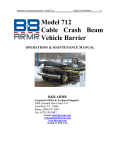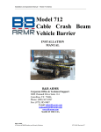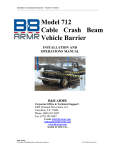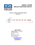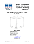
1
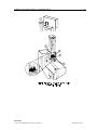
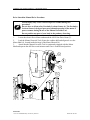
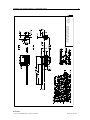
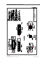
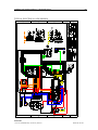
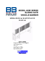
MODEL 4X0E SERIES SLIDING GATE VEHICLE BARRIER OPERATIONS & MAINTENANCE MANUAL B&B ARMR Corporate Office & Tech Support: 2009 Chenault Drive Suite 114 Carrollton, Tx 75006 Phone: (800) 367-0387 Fax: (972) 385-9887 E-mail: [email protected] [email protected] www.bb-armr.com MADE IN THE USA Installation and Operations Manual — Model 400E Series iv Your safety is extremely important to us. If you have any questions or are in doubt about any aspect of the equipment, please contact us. INTRODUCTION Welcome! Congratulations on your purchase of a B&B ARMR vehicle barrier. In addition to providing detailed operating instructions, this manual describes how to install, maintain, and troubleshoot your vehicle barrier. If you require additional assistance with any aspect of your vehicle barrier's installation or operation, please contact us. With years of experience in all aspects of perimeter security and related disciplines, our products are used throughout the world to control access and to protect people, equipment, and facilities. We offer a broad range of vehicle barrier and related security services: Routine barrier preventative maintenance or emergency repairs (including work on non-B&B ARMR products) Spare or replacement parts Custom designs or special installations Equipment upgrades (modernize your old equipment with state-of-the-art systems) Technical support via telephone and possible on site support with advanced scheduling. Safety Your safety is important to us. If you have any questions or are in doubt about any aspect of the equipment, please contact us. While B&B ARMR does not assume responsibility for injury to persons or property during installation, operation, or maintenance, we can provide verbal guidance, additional written instructions, or the services of a factory engineer. We're here to help you operate your vehicle barrier safely and effectively. As the user, you are responsible for correct and safe installation, operation, and maintenance of this equipment. Users must follow the specific instructions and safety precautions located in this manual. In addition they must: Be aware of and follow the safety standards of the Occupational Safety and Health Administration (OSHA), as well as other applicable federal, state, and local safety regulations and industry standards and procedures. For installation outside the United States, users must also follow applicable international, regional, and local safety standards. B&B ARMR A Division of B&B Roadway and Security Solutions 0400E-9001 Rev H2 Installation and Operations Manual — Model 400E Series v Engage only trained and experienced staff to install, operate, and maintain the equipment. Ensure that all repairs are performed correctly, using properly trained staff and the right tools and equipment. How to Contact Us If you have any questions or experience any problems with your vehicle barrier—or if we can help you with any other facility security issues—please contact us directly at: Corporate/Tech Support: B&B ARMR 2009 Chenault Drive Suite 114 Carrollton, TX 75006 USA Telephone: (972) 385-7899 Toll Free: (800) 367-0387 Fax: (972) 385-9887 E-mail: [email protected] [email protected] B&B ARMR A Division of B&B Roadway and Security Solutions 0400E-9001 Rev H2 Installation and Operations Manual — Model 400E Series vi Table of Contents INTRODUCTION ......................................................................................................................................... iv Welcome! .................................................................................................................................................iv Safety ........................................................................................................................................................iv How to Contact Us ................................................................................................................................... v 1. ORIENTATION ....................................................................................................................................... 7 1.1 Overview .......................................................................................................................................... 7 3. OPERATION ............................................................................................................................................ 9 3.1 Preliminary Checklist ....................................................................................................................... 9 3.2 Initial Operation..............................................................................................................................10 3.3 Initial Setup and Test ......................................................................................................................11 3.4 Operational Test..............................................................................................................................12 3.5 ECO Operation ...............................................................................................................................13 3.6 Barrier Operation during a Power Outage .....................................................................................13 3.7 Barrier Operation during a Power Outage – With Optional Manual Drive System .......................13 4. MAINTENANCE .....................................................................................................................................16 4.1 Introduction .....................................................................................................................................16 4.2 Monthly Inspections ........................................................................................................................16 4.3 Six-Month Inspections .....................................................................................................................16 5. TROUBLESHOOTING ...........................................................................................................................17 6. REFERENCE DRAWINGS .....................................................................................................................18 7. WARRANTY ............................................................................................................................................24 8. EQUIPMENT MAINTENANCE LOG FORM .......................................................................................25 B&B ARMR A Division of B&B Roadway and Security Solutions 0400E-9001 Rev H2 Installation and Operations Manual — Model 400E Series 7 1. ORIENTATION 1.1 Overview This manual addresses B&B ARMR’s Model 400/450 Electric Drive Cantilever Gates. Barrier Model Vehicle Weight Vehicle Speed U.S. Department of State Rating* 400 & 400A 15,000 pounds (~6,800 kg) 30 mph (~48 kph) K4 450 & 450A 15,000 pounds (~6,800 kg) 50 mph (~80 kph) K12 The gate speed is factory set at approximately one foot per second. Manual operation of the gate can be performed by lowering drive assembly, disengaging actuator from lock pins and manually pushing the gate. Motor controller ramps up and down the movement of the gate to reduce wear and shock on drive unit based on limit switch trip plate locations. Minimal wiring, no hydraulic hoses to pull. 1.1.1 Gate Leaf The gate leaf pickets are typically 1" square steel tubes spaced on 2.5" centers. The standard gate height is 108 inches (9 feet or 2.75 meters) above grade but custom sizes are available. Figure 1 Model 400 Cantilever Gate B&B ARMR A Division of B&B Roadway and Security Solutions 0400E-9001 Rev H2 Installation and Operations Manual — Model 400E Series 8 1.1.2 Drive Stanchion The drive stanchion supports the gate with the four main drive wheels and allows the drive unit to mesh with the rack located on the underside of the gate beam. Figure 2 Model 4x0E Drive Stanchion Figure 3 Drive Unit B&B ARMR A Division of B&B Roadway and Security Solutions 0400E-9001 Rev H2 Installation and Operations Manual — Model 400E Series 9 1.1.3 Receiver Stanchion The receiver stanchion captures (and locks in model 450) the end of the gate when the gate is fully closed. The Model 450 has a pair of two inch diameter stainless steel pins that are electrically actuated to lock the gate closed. Limit switches indicate the location of the lock pins. The actuator motor (2 wires) and its two limit switches (2 wires each) may share a ¾”conduit to the electrical enclosure. Figure 4 Lock pin Assembly (Model 450) 3. OPERATION 3.1 Preliminary Checklist Before operating the Model 4X0 Series vehicle barrier, go through the checklist below and verify that each of these steps has been completed. For your safety, complete each of these steps before operating the barrier! B&B ARMR A Division of B&B Roadway and Security Solutions 0400E-9001 Rev H2 Installation and Operations Manual — Model 400E Series 10 The breaker in the enclosure on the control circuit box is turned off. All traffic and pedestrians are clear of the barrier. The gate is mounted to the stanchions and does not bind when moved manually. The roller wheel axles are securely mounted and the set screws are tight. There is no side play on the roller wheels. The wheels have been greased The guide wheels have been adjusted so that they extend further than the main wheels (to avoid binding). Make sure the guide wheels on each end of the stanchion are both not tight to the gate. There should be about ¼ inch clearance between the sets of guide wheels and the ends of the gate. Verify that the roller wheels are spaced away from the sides of the I-Beam equally on both sides. The pinion is not engaged to the rack. The limit switch’s wiring must be verified, the motor direction confirmed, and the trip plates positioned correctly prior to engaging the motor/transmission assembly with the rack. 3.2 Initial Operation Perform the following steps the first time you operate the vehicle barrier, and also after replacing any major repairs. 3.2.1 Power Verification: Turn on the breaker located in the electrical enclosure on the side of the electrical control unit. Verify incoming power meets system requirements. Someone should remain at the breaker during the initial operation in case there is a malfunction and the unit must be shut down. 3.2.2 Before attempting to run the gate, check the control and safety inputs of the system manually. Check inputs and outputs to system submittal documentation. To access the input and output screen on the PLC verify the date/time screen is visible and press the right arrow key once to get to the Input screen and twice to get the output screen. Press the left arrow key to return to the date/time screen. Verify that OPEN LIMIT A and OPEN LIMIT B turns on appropriate PLC inputs. Verify that CLOSED LIMIT A and CLOSED LIMIT B turns on appropriate PLC inputs. Verify that any safety device turns on the SAFETY PLC input. Verify that the STOP input is on (factory jumper must be removed if external Stop button used – must be normally closed switch and if more than one, must be wired in series) Verify the OPEN command and CLOSE command turn on associated inputs. B&B ARMR A Division of B&B Roadway and Security Solutions 0400E-9001 Rev H2 Installation and Operations Manual — Model 400E Series 11 3.3 Initial Setup and Test 3.3.1 Motor Verification: If using a 3-phase motor ensure the motor turns in the correct direction when powered. Wire the motor as shown on the schematic. Provide an OPEN command to turn the pinion so that when engaged, would move the gate towards the drive stanchion. If the motor is turning the wrong way, turn off power breaker and reverse two of the power wires going to the motor. 3.3.2 Limit Switch Setup: The limit switches must be tripped in the correct order to correctly control the gate movement. The “A” limits are the slowdown limit controls (trips first), and the “B” limits are the stop controls (trips second). When the gate is fully open or fully closed, both (A & B) limits are tripped, and both inputs shall be seen on the I/O screen of the PLC. When the gate moves from either a fully open or fully closed position, it first releases the “B” limit, then the “A” limit. When it gets to the other position (opened/closed) it will first make “A” then “B. 3.3.3 Locking Pin Actuator (Model 450 only): Verify the locking pin control is enabled in the PLC by scrolling to “400Enble” on the PLC and make sure that it reads “Switch= OFF”. If a 400 gate is being used, there are no locking pins, and this parameter should be ON. Move the actuator to the up position when the system is powered use a jump wire between Q4-1 and Q4-2. If the system power is turned off, apply +24VDC to Q4-2 and 0VDC to Q52. Hold the jumper or DC power on until pins are fully retracted. Verify that the LOCK PIN UP input on the PLC is activated. Reverse the lock pins to the engaged position and verify the LOCK PIN DOWN input is activated. Leave the lock pins in the retracted (up) position. Before engaging the pinion with the rack, verify that the limit switches are mounted and wired correctly. Failure to do so could cause severe damage or injury. 3.3.4 Test CLOSE operation: Verify gate is positioned between limit switches and does not block locking pins (Model 450 only). Give the gate a CLOSE command and verify that the pinion turns in the direction that would move the gate towards the receiver stanchion. Manually trip CLOSE LIMIT A and verify the motor begins to slow. Manually trip CLOSE LIMIT B and verify motor stops. Verify the locking pin actuator (Model 450) lowers the locking pins until the LOCK PIN DOWN input comes on and the actuator stops. 3.3.5 Test OPEN operation: Give the gate an OPEN command. Verify the locking pins raise and the LOCK PIN UP input is activated. Verify the motor rotates correctly to move the gate in the open direction. Manually trip the first limit switch and verify the OPEN LIMIT A PLC input activates and the motor begins the slow. Manually trip the second limit and verify the OPEN LIMIT B activates. Verify the motor stops. The Model 450 system is designed with a software parameter (LPMRT) to limit the actuator run time in case of malfunction and the LOCK PIN DOWN input does not activate. The default value is 8 seconds. During a malfunction the lock pins will reverse to a retracted B&B ARMR A Division of B&B Roadway and Security Solutions 0400E-9001 Rev H2 Installation and Operations Manual — Model 400E Series 12 position and the RED INDICATOR output will flash rapidly. Investigation and adjustment of the trip plates and beam should be made to ensure the pins engage in the slots in the beam. To clear the alarm the CLOSE command can be re-issued. 3.3.6 Set the motor mount: With the gate in a half open position, and the spring on the motor drive assembly is in the factory compressed state, raise the assembly into the rack until the pinion gear meshes with the rack 80%. Move the gate to the open position, and observe the spacing between the pinion gear and rack. Move the gate to the closed position and observe the spacing. Using the vertical motor adjustments move the drive system until the spacing between the rack and pinion is engaged at least 80% for both fully open and fully closed. The spring system may compress if required to meet the 80% minimum requirement. 3.3.7 Install Safety stop rubber pads: With the stop plate off, install the rubber pads on the inside bottom lip of the gate beam. Place the end plate back on and tighten the bottom bolts first. Tighten top bolts last to ensure rubber pad is fully secured. If required both rubber pads can be placed on one side of the beam. Figure 5 End Plates 3.4 Operational Test 3.4.1 Give the gate an OPEN command. The locking pin will raise (Model 450), and the motor will accelerate and run to move the gate open. The first limit switch will begin the speed reduction of the motor. The second limit switch will stop the motor. If Model 400, the gate will move immediately upon receiving the open command. 3.4.2 Give the gate a CLOSE command. The motor will accelerate and run to move the gate. The first close limit switch will begin the speed reduction of the motor to the second close limit switch will stop the motor. Once the second close limit switch is tripped, the lock pin will engage (Model 450). B&B ARMR A Division of B&B Roadway and Security Solutions 0400E-9001 Rev H2 Installation and Operations Manual — Model 400E Series 13 3.4.3 Verify that there are no interferences between the moving parts and that the limit switches are hitting the trip plates correctly. Make any necessary adjustments. 3.4.4 Verify the operation of the gate is smooth for the entire travel length. 3.5 ECO Operation Emergency Close Operation (ECO) command acts identically to a CLOSE command except all safety inputs are ignored. It should only be used during an emergency. An ECO RESET must be issued after any ECO command before the gate will respond to an open command. 3.6 Barrier Operation during a Power Outage Disconnect the locking pin actuator from the locking pins and swing actuator out of the way to manually lift the locking pins (Model 450). Disengage and lower the motor drive assembly and manually open the gate. 3.7 Barrier Operation during a Power Outage – With Optional Manual Drive System If the system you are operating is equipped with the manual override drive system the following is done to move the gate. Your safety is extremely important to us. Be sure to follow all instructions. You are responsible for the correct and safe installation, operation, and maintenance of this equipment. Tools needed: 1. Manual Override Tool (supplied with original 450E equipment) 2. Fully charged, battery operated cordless drill 3. Access keys/codes to Receiver Stanchion, Locking Pin Access Door Receiver Stanchion Crash Pin Release 1. Open Crash Pin locking equipment access door (1) located on the top of the Receiver Stanchion assembly. 2. Use a tool or block (2) placed under the Locking Pin Plate (3) and then impress the button on the Pull Pin (4) to remove (this releases the electrical drive assembly from the Locking Pin assembly). 3. Raise the Locking Pin Plate assembly (3) approximately 15 cm (6 inches) and place the Pull Pin (4) in the hole located in the vertical weldment plate (5) to hole the Locking pins above the moving gate assembly. 4. Allow the Locking Pin Plate to rest on the Pull Pin. 5. Proceed to the Drive Stanchion Manual Drive Procedure. B&B ARMR A Division of B&B Roadway and Security Solutions 0400E-9001 Rev H2 Installation and Operations Manual — Model 400E Series B&B ARMR A Division of B&B Roadway and Security Solutions 14 0400E-9001 Rev H2 Installation and Operations Manual — Model 400E Series 15 Drive Stanchion Manual Drive Procedure Serious injury may occur if electrical power resumes during this procedure. Do not alter or defeat safety Proximity Lockout Sensor (6). The Proximity Lockout Sensor is design to prevent accidental operation of the motor if power resumes during the use of the Manual Override Tool. Do not position any part of your body in the pathway of moving. 1. Locate the electric Drive Motor underneath the 450E Gate Drive Beam (7). 2. Load the Manual Override Tool (8) into the cordless drill and align tool over the Motor Shaft (9), located inside the large of the Motor Shroud (10) 3. Assure that the Manual Override Tool is consistently engaged with the Motor Shaft and operate the drill for several minutes until Gate is in the desired position. B&B ARMR A Division of B&B Roadway and Security Solutions 0400E-9001 Rev H2 Installation and Operations Manual — Model 400E Series 16 4. MAINTENANCE Do not attempt repairs unless you are trained and qualified. This vehicle barrier can cause equipment damage and severe injury if it is operated or maintained improperly. 4.1 Introduction The Model 4x0E gates are designed to be largely maintenance free. As with any complex electromechanical device, they must be regularly inspected to ensure they are operating correctly. We recommend a monthly and biannual inspection as described below. Please contact B&B ARMR for assistance with inspections, maintenance, or repairs. Component damage is likely if a vehicle strikes the barrier. If this occurs, contact B&B ARMR. We will help you assess the damage and make sure there is no hidden damage that will compromise safety or effectiveness. We will help you determine which components should be replaced, and will provide guidance on the repairs. 4.2 Monthly Inspections We recommend you perform the following visual inspections monthly. ** Ensure main power switch is OFF when inspecting, adjusting or replacing drive system components** 4.2.1 During the opening and closing cycle, verify the gate operates smoothly and does not bind. Adjust the guide wheels as necessary to eliminate binding. 4.2.2 Inspect the motor pinion gear for wear, and verify that the proper spacing is present between the spur gear and gear rack. Ensure all bolts are tight. 4.2.3 Verify gate limit switches and locking pin limit switches (Model 450) are in the proper position and operational. Adjust and tighten if necessary. 4.2.4 Verify locking pin is aligned with beam assembly (Model 450). 4.2.5 Inspect rack, pinion, and wheel areas and add grease or cosmoline as needed. 4.2.6 Grease 8” drive wheels. 4.2.7 Grease pillow block bearings on motor assembly. 4.2.8 Inspect cradle pivot drive assembly components for wear, and adjust assembly if needed. Ensure all bolts are tight. 4.2.9 Verify chain tension and adjust as needed. 4.2.10 Verify the safety devices are functioning correctly. 4.2.11 Verify electrical connections are tight. 4.2.12 Visually inspect the condition of the finish. If corrosion is present, wire brush and sand the area then repaint with primer and matching color. 4.3 Six-Month Inspections We recommend you perform the following inspections every six months. B&B ARMR A Division of B&B Roadway and Security Solutions 0400E-9001 Rev H2 Installation and Operations Manual — Model 400E Series 17 4.3.1 Repeat the monthly inspections and adjustments. 4.3.2 Verify the fluid level in the transmission by removing the oil level plug. If fluid is not present, fill with Mobil SHC 629 or equivalent. 4.3.3 Inspect guide wheels. Check for proper adjustment and wear on wheels or gate. Readjust if necessary. 4.3.4 Inspect roller wheels, grease fittings. Make sure oil seals (on side of wheels) are still tight and no grease is coming out the sides of them. Make sure that the wheels and nuts are still tight, and the wheels are turning freely. After any major repairs, review the installation setup instructions before returning the barrier to service 5. TROUBLESHOOTING The table below provides guidance on identifying and correcting issues with your Model 400 Series vehicle barrier. If you encounter problems that you cannot fix, contact B&B ARMR and we will gladly work with you to correct them. Model 4x0E Troubleshooting Guide Symptom Gate does not open or close Gate makes noise during operation B&B ARMR A Division of B&B Roadway and Security Solutions Actions 1. Check power, fuses 2. Check Limit Switches 3. Check PLC inputs 4. Check PLC outputs 5. Check that safeties are clear 6. Check push button operation 7. Check locking pin and limit switch, gate will not open unless the pins are up and LOCK PIN UP input is activated on the PLC. 8. Manually open the gate by to see if the problem is mechanical or electrical. If mechanical, check for binding on the gate. 1. Check that roller wheel bearings are greased 2. Check that gate is not moving too fast 3. Check that the guide wheels are properly adjusted 4. Check that the spur gear is properly adjusted to the gear rack 0400E-9001 Rev H2 Installation and Operations Manual — Model 400E Series Symptom Gate moves too slowly Traffic indicator light does not change Locking pins are moving but not giving signals up or down to I3 18 Actions 1. Check for mechanical binds (guide wheels out of adjustment, debris under the wheels or on the inside of gate 1. Check proper limit switch operation 2. Check bulbs 3. Check PLC outputs 1. Check the limit switches at the locking pin mechanism 6. REFERENCE DRAWINGS The following drawings are provided for reference only. For job specific drawings and details please refer to the Submittal Documentation specific to the job. For replacement components and parts breakdown, please contact B&B ARMR tech support. B&B ARMR A Division of B&B Roadway and Security Solutions 0400E-9001 Rev H2 GENERIC 400 CANTILEVER SLIDING GATE 20' RIGHT HAND CLEAR OPENING 9' GATE HEIGHT B&B ARMR 2009 Chenault Dr. #114 Carrollton, Tx 75006 800-367-0387 Installation and Operations Manual — Model 400E Series B&B ARMR A Division of B&B Roadway and Security Solutions 19 0400E-9001 Rev H2 Installation and Operations Manual — Model 400E Series 400 CRASH BEAM LEFT HAND CLEAR OPENING B&B ARMR 2009 Chenault Dr. #114 Carrollton, Tx 75006 800-367-0387 20 B&B ARMR A Division of B&B Roadway and Security Solutions 0400E-9001 Rev H2 Installation and Operations Manual — Model 400E Series 450A CANTILEVER SLIDING GATE 20' LEFT HAND CLEAR OPENING B&B ARMR 2009 Chenault Dr. #114 Carrollton, Tx 75006 800-367-0387 21 B&B ARMR A Division of B&B Roadway and Security Solutions 0400E-9001 Rev H2 Installation and Operations Manual — Model 400E Series 400 SERIES CANTILEVER SLIDING GATE FOUNDATIONS B&B ARMR 2009 Chenault Dr., #114 Carrollton, Tx 75006 800-367-0387 22 B&B ARMR A Division of B&B Roadway and Security Solutions 0400E-9001 Rev H2 Installation and Operations Manual — Model 400E Series 23 TYPICAL ELECTRICAL (450E SHOWN) B&B ARMR A Division of B&B Roadway and Security Solutions 0400E-9001 Rev H2 Installation and Operations Manual — Model 400E Series 24 7. WARRANTY BBRSS warranties for a period of one (1) year FOB manufacturing facility, unless otherwise specified by BBRSS in writing, from defects due to faulty material or workmanship. Damage due to handling during shipment and installation are not covered under warranty. BBRSS assumes no responsibility for service at customer site. BBRSS is in no event responsible for any labor costs under the warranty. Subject to the above limitation, all service, parts, and replacements necessary to maintain the equipment as warranted shall be furnished by others. BBRSS shall not have any liability under these specifications, other than for repair or replacement as described above for faulty product material or workmanship. Equipment malfunction or equipment failure of any kind, caused for any reason, including, but not limited to unauthorized repairs, improper installation, installation not performed by BBRSS authorized personnel, incoming supply power is outside the tolerance for the product, failure to perform manufacturer’s suggested preventative maintenance, modifications, misuse, accident, catastrophe, neglect, natural disaster, are not under warranty. The exclusive remedy for breach of any warranty by BBRSS shall be the repair or replacement at BBRSS’s option, of any defects in the equipment. IN NO EVENT SHALL BBRSS BE LIABLE FOR CONSEQUENTIAL OR SPECIAL DAMAGES OR ANY KIND OF PERSONAL DAMAGES. Except as provided herein, BBRSS makes no warranties or representations to consumer or to anyone else and consumer hereby waives all liability against BBRSS as well as any other person for the design, manufacture, sale, installation, and/or servicing of the Products. THE FOREGOING WARRANTIES ARE IN LIEU OF ALL OTHER WARRANTIES EXPRESS OR IMPLIED, INCLUDING THE IMPLIED WARRANTY OF MERCHANTABILITY AND FITNESS FOR A PARTICULAR PURPOSE. NO OTHER WARRANTIES EXIST. Any modification or alteration by anyone other than BBRSS will render the warranty herein as null and void. B&B ARMR A Division of B&B Roadway and Security Solutions 0400E-9001 Rev H2 Installation and Operations Manual — Model 400E Series 8. 25 EQUIPMENT MAINTENANCE LOG FORM Product Type: ________________________ Location: ____________________________ Jan Checklist Complete Yes No Feb Yes No Mar Yes No Apr Yes No May Yes No Jun Yes No Jul Yes No Aug Yes No Sep Yes No Oct Yes No Nov Yes No Year Yes No Date Date Performed By Performed By Checklist Complete Jan Yes No Feb Yes No Mar Yes No Apr Yes No May Yes No Jun Yes No Jul Yes No Aug Yes No Sep Yes No Oct Yes No Nov Yes No Year Yes No B&B ARMR A Division of B&B Roadway and Security Solutions B&B ARMR 800-367-0387 [email protected] Anomalies Notes Anomalies Notes 0400E-9001 Rev H2