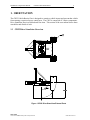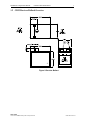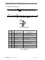
1
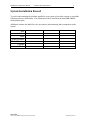
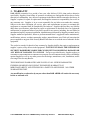
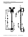
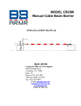
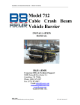
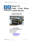
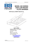
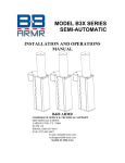
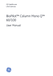
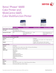
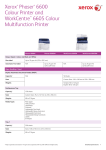
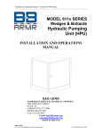
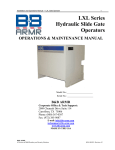
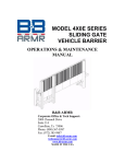
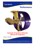
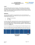
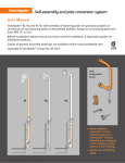
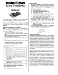
MODEL CR25M Manual Cable Beam Barrier INSTALLATION AND OPERATIONS MANUAL B&B ARMR Corporate Office & Tech Support: 2009 Chenault Drive Carrollton, TX 75006 Suite 114 Phone: (972) 385-7899 Toll Free: (800) 367-0387 Fax: (972) 385-9887 E-mail: [email protected] [email protected] www.bb-armr.com MADE IN THE USA Installation & Operations Manual CR25M Cable Beam Barrier 2 INTRODUCTION Welcome Congratulations on your purchase of a B&B ARMR warning gate. We have years of experience in all aspects of perimeter security and related disciplines, and our products are used throughout the world to control access and to protect people, equipment, and facilities. Your warning gate is designed to give you years of smooth, trouble-free operation. In addition to providing detailed operating instructions, this manual describes how to install, maintain, and troubleshoot your vehicle barrier. To make it easy to locate the information you need, we've included a detailed Table of Contents immediately following this Introduction. All of this is important information, so be sure to keep the manual available for reference. If you need help with any aspect of your vehicle barrier's installation or operation, please contact us. We offer a broad range of vehicle barrier and related security services, so you can also call on us for: Turnkey installations Routine barrier preventative maintenance or emergency repairs (including work on nonB&B ARMR products) Spare or replacement parts Custom designs or special installations Equipment upgrades Ancillary security equipment Technical support available by phone or in person with advanced scheduled notice. Safety The exclamation point within an equilateral triangle is intended to alert the user to the presence of important operating and maintenance (servicing) instruction in the literature accompanying the product. Your safety is important to us. If you have any questions or are in doubt about any aspect of the equipment, please contact us. While B&B ARMR does not assume responsibility for injury to persons or property during installation, operation, or maintenance, we can provide verbal guidance, additional written instructions, or the services of a factory engineer. We're here to help you operate your vehicle barrier safely and effectively. As the user, you are responsible for correct and safe installation, operation, and maintenance of this equipment. Users must follow the specific instructions and safety precautions located in this manual. In addition: Be aware of and follow the safety standards of the Occupational Safety and Health Administration (OSHA), as well as other applicable federal, state, and local safety regulations and industry standards and procedures. For installation outside the United States, users must also follow applicable international, regional, and local safety standards. Engage only properly trained experienced staff to install, operate, and maintain the equipment. B&B ARMR A Division of B&B Roadway and Security Solutions 0M25-9001 Rev D2 Installation & Operations Manual CR25M Cable Beam Barrier 3 Ensure that all repairs are performed correctly, using properly trained staff and the right tools and equipment. How to Contact Us If you have any questions or experience any problems with your vehicle barrier—or if we can help you with any other facility security issues—please contact us directly at: Corporate/Tech Support: B&B ARMR 2009 Chenault Drive Suite 114 Carrollton, TX 75006 USA Telephone: (972) 385-7899 Toll Free: (800) 367-0387 Fax: (972) 385-9887 E-mail: [email protected] [email protected] B&B ARMR A Division of B&B Roadway and Security Solutions 0M25-9001 Rev D2 Installation & Operations Manual CR25M Cable Beam Barrier 4 System Installation Record To assist in documenting the products installed in your system, please take a minute to record the following reference information. This information can be located on the blue B&B ARMR model number plate. Additional columns are added for your convenience in documenting other components in the system. Site: Job #: Date: Serial Number: Model Number: Voltage: Phase: B&B ARMR A Division of B&B Roadway and Security Solutions 0M25-9001 Rev D2 Installation & Operations Manual CR25M Cable Beam Barrier 5 Table of Contents INTRODUCTION ................................................................................................................... 2 Safety .......................................................................................................................................... 2 How to Contact Us .................................................................................................................... 3 System Installation Record ........................................................................................................ 4 1. 2. ORIENTATION ............................................................................................................... 6 1.1 CR25 Drive Stanchion Overview ................................................................................................................6 1.2 CR25 Receiver Bollard Overview ...............................................................................................................7 1.3 CR25 Gate Arm Overview ..........................................................................................................................8 INSTALLATION .............................................................................................................. 9 2.1 Field Balancing Instructions -CR25 Barriers ............................................................................................9 2.2 Recommended Lubricant ..........................................................................................................................10 3. WARRANTY ................................................................................................................... 11 4. GENERAL LAYOUT ..................................................................................................... 12 5. PREVENTATIVE MAINTENANCE ........................................................................... 13 5.1 Lubrication Schedule ................................................................................................................................13 5.2 Arm Adjustment ........................................................................................................................................13 5.3 Visual Inspection ......................................................................................................................................13 B&B ARMR A Division of B&B Roadway and Security Solutions 0M25-9001 Rev D2 Installation & Operations Manual CR25M Cable Beam Barrier 6 1. ORIENTATION The CR25 Vehicle Barrier Gate is designed to contain a vehicle impact and prevent that vehicle from entering a restricted access control area. The CR25 is comprised of 3 major components: Drive Stanchion, Receiver Bollard and Gate Arm. This section of the user manual shows these assemblies and details of each. 1.1 CR25 Drive Stanchion Overview Figure 1 CR25 Drive Stanchion External Parts B&B ARMR A Division of B&B Roadway and Security Solutions 0M25-9001 Rev D2 Installation & Operations Manual CR25M Cable Beam Barrier 7 1.2 CR25 Receiver Bollard Overview Figure 2 Receiver Bollard B&B ARMR A Division of B&B Roadway and Security Solutions 0M25-9001 Rev D2 Installation & Operations Manual CR25M Cable Beam Barrier 8 1.3 CR25 Gate Arm Overview Figure 3 CR25 Gate Arm ITEM NO QTY PART NUMBER 1 AR ACW-P010 2 2 1701-0200 3 1 0025-0515 4 1 0025-0603 5 1 0025-0540 6 1 0025-0054-XXX 7 AR PRS-3932-12R 8 AR PRS-3930-12W 9 1 0100-0615 10 2 0025-0583 11 1 0160-0006 DESCRIPTION Counterweight Bearing, Pillow Block, 2” Bar, Horizontal, Lock Bar, Vertical, Padlock Guide, Arm Cable Arm, XXX=Clear Opening Stripe, Red Reflective Stripe, White Reflective Bracket, Truss, Pair Spacer, Truss Cable, Arm, 7/8” Table 1 CR25M Parts B&B ARMR A Division of B&B Roadway and Security Solutions 0M25-9001 Rev D2 Installation & Operations Manual CR25M Cable Beam Barrier 9 2. INSTALLATION NOTE: Failure to install your barrier properly could cause damage to the operating mechanism. 1. Read the instructions and review the project submittal drawings thoroughly. If you do not understand any part of these instructions, please contact the manufacturer. 2. Set foundation as outlined in the project submittal package. 3. Check the anchor bolt locations and prepare the foundation for the barrier. Information on anchor bolt locations can be obtained from the project submittal package. 4. Set the barrier operator and be sure to seal the bottom with duct seal. Housing must be level. Anchor bolts must be tightened evenly. 5. Remove side arm tube cover plate. Locate pillow block bearings. Do not tighten set screws. Now center assembly with housing. When assembly is correctly centered, tighten bearing set screws. 6. Insert arm, with end lock intact, into the main arm tube base. Push tube far enough to make the cable connections at the pivot. After cables have been securely bolted to the pivot mechanism, extend arm so that the end lock saddles satisfactorily over the anchor assembly (on the bollard). Slide lock collar into place and tighten allen bolts. NOTE: If end lock fails to line up properly, loosen pillow block bearing bolts and rotate laterally. Re-tighten bolts. Now tighten arm base bolts securely. Replace side arm tube cover plate (tighten bolts securely). 7. With the arm in the down position, install the allotted amount of counterweights on the side arm tube assembly. Tighten bolts securely. 8. With the barrier in the lowered position, check end lock mechanism for any type of hindrance with bollard post and adjust accordingly if required. 9. Install and adjust the turnbuckles. Turnbuckles should be snug. DO NOT over tighten as you can warp the gate arm. 2.1 Field Balancing Instructions -CR25 Barriers IMPORTANT: EVERY BARRIER IS BALANCED AT THE FACTORY BEFORE IT IS SHIPPED. IF ANY ADDITIONS OR CHANGES ARE MADE TO THE BARRIER ARM IN THE FIELD, THE BARRIER MAY REQUIRE RE-BALANCING. AN UNBALANCED ARM MAY DAMAGE THE OPERATOR. If any additions or changes are made to the barrier, the following guidelines will help you determine what changes, if any, need to be made to the barrier balance: 1. Make the desired changes to the barrier arm. 2. Secure the tip end of the arm to prevent injury or accident. B&B ARMR A Division of B&B Roadway and Security Solutions 0M25-9001 Rev D2 Installation & Operations Manual CR25M Cable Beam Barrier INDICATIONS Barrier arm tends to raise Requires more than 20 lbs. to keep it closed to traffic. Barrier arm tends to lower Requires more than 20 lbs. to keep it open to traffic. 10 PROBLEM Barrier is counterweight heavy. SOLUTION Counterweights can be removed. Barrier is arm heavy. Counterweights can be added. A properly balanced barrier can be manually operated by one person pushing on the end of the counterweight mounting channel. It should require only 20 lbs. of force to manually operate the barrier. Calculating Counterweight Requirements 1. Disconnect arm drive by removing top connecting rod bolts located on the side of the operator. 2. Mark any place on the barrier arm and attach a weighing scale to the arm at that point. 3. Measure how much weight, in pounds, it takes to start raising the barrier arm. (arm lbs). 4. Measure, in inches, the distance from the weight point to the center of the pivot point (arm dist). 5. Measure, in inches, the distance from center of pivot point to center of counterweight (cw dist). 6. Follow this formula to get the proper amount of counterweight to add to barrier. arm lbs x arm dist cw dist 2.2 Recommended Lubricant The following grease is recommended by the manufacturer of the flange type bearings used on both the warning gates and barriers: Texaco Marfax or Texaco Starplex grease is the manufacturer’s first choice. If this grease is not available, consult your local supplier for an equivalent. B&B ARMR A Division of B&B Roadway and Security Solutions 0M25-9001 Rev D2 Installation & Operations Manual CR25M Cable Beam Barrier 11 3. WARRANTY B&B-ARMR warranties for a period of one year, after delivery F.O.B. plant, unless otherwise specified by Supplier, from failure of operation in ordinary use and against defects due to faulty material or workmanship. Any defective equipment in the Barrier shall be returned to the factory, at Supplier’s option, for repair or replacement, and Supplier assumes no responsibility for service at any consumer site. Supplier is in no event responsible for any labor costs under the warranty. Subject to the above limitation, all service, parts, and replacements necessary to maintain the equipment as warranted shall be furnished by the end user. Supplier shall not have any liability under these specifications, other than for repair or replacement as described above for equipment malfunction or equipment failure of any kind, caused for any reason, including, but not limited to unauthorized repairs, improper installation, installation not performed by Supplier personnel, nor by Supplier authorized personnel, failure to perform manufacturer’s suggested routine maintenance, modifications, misuse, accident, catastrophe, neglect, natural disaster, act of God or if at any time the power supplied to any part of the Security Barrier falls short or exceeds the rate of tolerance for the equipment. The exclusive remedy for breach of any warranty by Supplier shall be the repair or replacement at supplier’s option, of any defects in the equipment. IN NO EVENT SHALL THE SUPPLIER OF SECURITY BARRIER BE LIABLE FOR CONSEQUENTIAL OR SPECIAL DAMAGES OR ANY KIND OF DAMAGES TO ANYONE. Except as provided herein, Supplier makes no warranties or representations to consumer or to anyone else and consumer hereby waives all liability against Supplier as well as any other person for the design, manufacture, sale, installation, and/or servicing of the Security Barrier. THE FOREGOING WARRANTIES ARE IN LIEU OF ALL OTHER WARRANTIES EXPRESS OR IMPLIED, INCLUDING THE IMPLIED WARRANTY OF MERCHANTABILITY AND FITNESS FOR A PARTICULAR PURPOSE. NO OTHER WARRANTIES EXIST. Any modification or alteration by anyone other than B&B ARMR will render the warranty herein as null and void. © 2013 B&B ARMR A division of B&B Roadway and Security Solutions 0M25-9001 REV D May-14 Installation & Operations Manual CR25M Cable Beam Barrier 12 4. GENERAL LAYOUT © 2013 B&B ARMR A division of B&B Roadway and Security Solutions 0M25-9001 REV D May-14 Installation & Operations Manual CR25M Cable Beam Barrier 13 5. PREVENTATIVE MAINTENANCE 5.1 Lubrication Schedule Pillow Block Bearings: 1. Grease with Texaco Marfak 2 or equal. 2. Wipe off excess. Connecting Rod Ends (Items11 & 13): 1. Grease with Texaco Marfak 2 or equal. 2. Wipe off excess. 5.2 Arm Adjustment Raise and lower the arm and observe the operation. Cable guide should not interfere with the receiver pin. Counterweights should not rub or come in contact with the bollard. Check and adjust the truss cable tension. DO NOT over tighten the cables. 5.3 Visual Inspection Inspect the bollard for signs of rust and touch up surface as needed. © 2013 B&B ARMR A division of B&B Roadway and Security Solutions 0M25-9001 REV D May-14