1
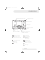
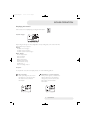
Project2:Layout 1
5/1/09
10:43
Page 2
INSPIRED EFFICIENCY
ETHOS 70, 90, 110 & 130
Wall mounted gas fired
condensing boilers
USER MANUAL
Issue 05/08
Project2:Layout 1
5/1/09
10:43
Page 3
USER MANUAL | Ethos 70 - 130
Introduction
The Mikrofill Ethos Boiler you have purchased has been designed and manufactured in Britain and represents the
very best in quality and performance,
This User Manual is designed to Guide you through the many user settings available to ensure optimum operating
conditions. Please read this manual thoroughly, careful use of the controls will result in lower greenhouse gas
emissions and reduced operating cost.
The Ethos range of boilers incorporate a fully integrated microprocessor control system
that offers the following user settings
Heating Time Control
Domestic Hot water Time Control (optional HWS sensor required)
Weather Compensation (optional outside sensor required)
Holiday period programming
Night Set Back
The Optimised start facility is pre programmed and requires no user adjustment., all other settings and adjustments
will have been factory set.
Any procedures not described in this user manual should only be undertaken by a competent qualified person,
if in doubt contact Mikrofill technical dept. on 08452 606020
We recommend a regular maintenance regime that should include at least one annual service. Extended warranties
inclusive of annual service are available from Mikrofill Systems Ltd. For further details please contact the
HELPLINE on 08452 606020.
2
User Manual
Project2:Layout 1
5/1/09
10:43
Page 4
BOILER MODULE
DHW selection button
Heating selection button
Show information
Settings accept
Chimney sweep function
STB test
Manual mode
Quit setting
Service plug (BSB)
Adjust room comfort setpoint
Navigation and settings
Heating to Comfort setpoint
Info level activated
Heating to Reduced setpoint
Programming activated
Heating to frost protection setpoint
Heating temporarily
switched off
ECO function active
Process running - please wait
Holiday function active
Change battery
Reference to heating circuit
Burner operating
Maintenance / special operation
Error messages
3
User Manual
Project2:Layout 1
5/1/09
10:43
Page 5
BOILER OPERATION
Selecting heating module
This setting is used to switch between the different operating modes.
The selection made is indicated by a bar which appears below the
respective symbol.
Automatic mode
Automatic mode controls the room temperature according to the time program.
Characteristics of automatic mode:
Heating mode according to the time program
Temperature setpoints according to heating program “Comfort setpoint“
Protective functions active
Automatic summer / winter changeover (ECO functions)
Continuous operation
or “Reduced setpoint“
or
Continuous operation or Continuous operation maintains the room temperature at the selected operating level.
Heating to Comfort setpoint
Heating to Reduced setpoint
Characteristics of continuous operation:
Heating mode with no time program
Protective functions active
Automatic summer / winter changeover (ECO functions)
4
User Manual
Project2:Layout 1
5/1/09
10:43
Page 6
BOILER OPERATION
Protection
When using protection, the heating system is off. But it remains protected against frost
(frost protection temperature) provided there is no power failure.
Characteristics of Protection:
Heating off
Temperature according to frost protection
Protective functions active
Automatic summer / winter changeover (ECO functions) and automatic 24-hour heating limit active
Selecting DHW heating mode
The button is used to switch DHW heating mode on and off. The selection made is
indicated by a bar which appears below the respective symbol.
DHW heating
On
The DHW is heated according to the selected switching program.
Off
No DHW heating, the protective function is active.
Triggering is effected by keeping the DHW operating mode button on the
operator or room unit depressed for at least 3 seconds.
It can also be started when:
The operating mode is “Off“
Operating mode changeover acts via H1 or centrally (LPB)
All heating circuits use the holiday function
Adjusting the room temperature setpoint
Turn the setting knob to increase or decrease the Comfort setpoint
For the Reduced setpoint
Press OK
Select operating page “Heating circuit“ and
Adjust the “Reduced setpoint“
If no external sensors are connected, the boiler flow temperature will be determined by using the heating
curve with an external temperature of 0°C. Please see following graph for equivalent temperatures.
After each re-adjustment, wait at least 2 hours, allowing the room temperature to
adapt.
5
User Manual
Project2:Layout 1
5/1/09
10:43
Page 7
BOILER OPERATION
Heating curve
The rate of change, with respect to weather compensation, is adjusted by the heating curve setpoint,
selection of a higher setpoint will result in a higher rate of temperature gain. Reducing the setpoint
will result in a lower rate of temperature gain.
Increase adjustment: Raises the flow temperature, especially when outside temperatures are low.
Decrease adjustment: Lowers the flow temperature, especially when outside temperatures are low.
Displacement of heating curve
Parallel displacement of the heating curve is used to change the flow temperature evenly across the entire outside
temperature range or, in other words, if the room temperature is always too high or too low, a readjustment must
be made with the help of parallel displacement.
Adaptation of the heating curve
Adaptation of the heating curve is used by the controller to automatically adapt the heating curve to the prevailing
conditions. In that case, a readjustment of the heating curve slope and parallel displacement is not required.
It can only be switched on or off.
Boiler Temperature setting
Comfort
Setpoint
Boiler
Temperature
Comfort
Setpoint
Boiler
Temperature
Above table based on a heat slope of 2.0 at 0°c outside air temperature
6
User Manual
Project2:Layout 1
5/1/09
10:43
Page 8
BOILER OPERATION
Displaying information
Various data can be displayed by pressing the info button.
Possible displays
Depending on the type of unit, configuration and operating state, some of the info lines
listed below may not appear.
Display:
Possible error messages
Possible service messages
Possible special mode messages
Other displays:
Room temperature
State of DHW
State of boiler
Boiler temperature
Outside temperature
Date and time of day
DHW temp 1
State of heating circuit 1
Exception
In exceptional cases, the basic display shows one of the following symbols:
Error messages
If this symbol appears, an error in
the plant has occurred. Press the
info button and read further
information
Maintenance or special operation
If this symbol appears, a maintenance
alarm is delivered or the plant has
changed to special mode. Press the
info button and read further
information.
7
User Manual
Project2:Layout 1
5/1/09
10:43
Page 9
BOILER OPERATION
Manual operation
When manual operation is active, the relays are no longer energized and deenergized according to the control state,
but are set to a predefined manual operation state depending on their function.
The burner relay energized in manual control can be deenergized by the electronic temperature controller (TR).
Setpoint adjustment in Manual control
After manual control has been activated, a change to the basic display must be made.
There, the maintenance / special mode symbol appears.
Press the info button to switch to info display “Manual mode“, where the setpoint can be adjusted.
Chimney sweep function
The chimney sweep function is activated by a short press (maximum 3 seconds) on the chimney sweep button.
This function produces the operating state required to make emission measurements (flue gas, maximum load only).
8
User Manual
Project2:Layout 1
5/1/09
10:43
Page 10
PROGRAMMING
Setting principle
Settings that cannot be made directly with the operating elements are made in the form of programming.
For this purpose, the individual settings are structured in the form of operating pages and operating lines, thus
forming practical groups of settings. The following example shows how to set the time of day and the date.
Example: “Setting the time of day“
Press ESC to go one step back at a time, readjusted values are not be adopted.
If no setting is made for 8 minutes, the display returns automatically to the basic display.
Operating lines may be hidden, depending on the type of controller, the configuration made
and the user level.
Basic display.
If the basic display is not shown,
press the ESC button to return to it.
Press OK.
The bottom section of the display
shows a number of operating pages.
Turn the setting knob until
operating page Time of day and
date appears.
Press OK to confirm.
In the bottom section of the display, the
first operating line of operating page
Time of day and date appears.
Turn the setting knob until operating line
Hours / minutes appears.
To confirm, press OK.
9
User Manual
Project2:Layout 1
5/1/09
10:43
Page 11
PROGRAMMING
The display shows the hours
flashing .
Turn the setting knob until the
hours of the time of day are
correct.
To confirm, press OK.
The display shows the minutes
flashing.
Turn the setting knob until the
minutes of the time of day are
correct.
To confirm, press OK.
The settings are saved and the
displays stops flashing.
Now, you can make further settings
or you press the operating mode
button to return to the basic
display.
Now, you see the basic display again.
10
User Manual
Project2:Layout 1
5/1/09
10:43
Page 12
PROGRAMMING
User levels
The user levels only allow authorized user groups to change settings. To reach the required
user level, proceed as follows:
Basic display.
If the basic display is not shown,
press the ESC button to return to it.
Press OK.
You are on the user level Enduser.
Press the info button for 3
seconds.
You are now given a choice of user levels.
Turn the setting knob until the required
user level is reached.
Press OK.
You are now on the required
user level.
11
User Manual
Project2:Layout 1
5/1/09
10:43
Page 13
PROGRAMMING
Setting structure “Enduser”
The example given here shows that certain user levels do not allow certain settings to be
made. The example shows them highlighted. On the unit, they are hidden.
Setting structure ”Heating engineer“
12
User Manual
Project2:Layout 1
5/1/09
10:43
Page 14
PROGRAMMING
List of displays
Error code
Error Code
Description of maintenance
10
20
28
40
50
81
105
109
110
113
117
118
121
126
127
128
129
131
133
146
178
217
218
320
Outside temperature sensor error
Boiler temperature 1 sensor error
Flue gas temperature sensor error
Return temperature 1 sensor error
DHW temperature 1 sensor error
Short-circuit LPB
Maintenance message
Boiler temperature supervision
Lockout by SLT
Safety shutdown flue gas
Upper pressure limit (crossed)
Critical lower pressure limit (crossed)
Flow temperature 1 (HC1) supervision
DHW charging supervision
Legionella temperature not reached
Loss of flame in operation
Wrong air supply
Burner fault
Safety time exceeded
Configuration error common message
Temperature limiter heating circuit 1
Sensor error common message
Pressure supervision common message
DHW charging temperature sensor error
Maintenance code
Error Code
Description of maintenance
1
2
3
5
Burner hours run exceeded
Burner starts exceeded
Maintenance interval exceeded
Water pressure heating circuit too low
(dropped below lower pressure limit 1)
Water pressure 2 heating circuit too low
(dropped bel ow lower pressure limit 2)
Replace battery of outside sensor
Maximum flue gas temperature exceeded
Water pressure 3 too low
(dropped below lower pressure limit 3)
18
10
21
22
Special operation code
Error Code
Description of maintenance
301
302
303
309
310
314
Manual operation
SLT test
Chimney sweep function
Simulation outside temperature
Alternative energy operation
Economy mode
13
User Manual
Project2:Layout 1
5/1/09
10:43
Page 15
PROGRAMMING
Switching-on the appliance
1 Open the gas valve.
2 Switch on the boiler using the on/off switch on the control panel.
3 Set the type of operation to “automatic operation
” using the “heating selection” button.
Switching-off the appliance
The appliance can be switched off in three ways:
A The boiler remains available for hot water operation. Using the “heating selection” button,set the
type of operation to .
B The boiler is out of operation and only comes into operation due to the automatic frost protection
system. Using the “heating selection” button, set the type of operation to .
C Switch off the boiler completely.
1 Switch off the boiler using the on/off switch.
2 Close the gas valve.
Warnings
The appliance should be installed by a competent installer.
These operating instructions should be closely followed.
If the cause of the fault cannot be determined, contact the Service department. Never carry out repairs
on your own.
14
User Manual
Project2:Layout 1
5/1/09
10:43
Page 16
NOTES
Notes
Boiler Model:
Serial Number:
Installer:
Registration Number:
15
User Manual
Project2:Layout 1
5/1/09
10:43
Page 1
MIKROFILL SYSTEMS LTD
WEST COURT
MERSE ROAD
NORTH MOONS MOAT
REDDITCH
WORCESTERSHIRE
B98 9HL
T: +44 (0)8452 60 60 20
F: +44 (0)8452 60 60 21
E: [email protected]
W: www.mikrofill.com
0087