1
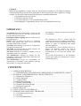
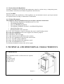
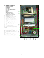
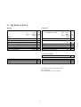
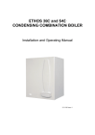
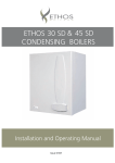
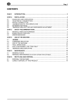
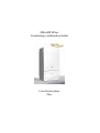
Mikrofill Ethos
Condensing combination boiler
User Instructions
24cc
CE Mark
Mikrofill gas appliances comply with the requirements contained in CE Mark documents
contained with European directives applicable to them. In particular, these appliances comply
with the CE directives and technical specifications contained within them :
? Gas Appliances directive 90/396
? Efficiencies directive 92/42
? Low tension directive 73/23 (modified from 93/68)
? Electromagnetic Compatibility directive 89/396 (modified from 93/68)
IMPORTANT !
The manual must be read thoroughly, so that you will
be able to use the boiler in a safe way. And it must be
kept for referance in the future.
Installation and first lighting must be carried out by a
competent person.
Repairs must be carried out only by a competent
person, using genuine spare parts. Do no more than
switching off the boiler yourself.
The boiler allows heating up of water to a temperature
less than the boiling point.
The boiler can be used only for those purposes for
which it has been specially designed.
The boiler must not be touched by children or by an
unfamiliar person to its operation.
The manufacturer disclaim all liability for any
translations of the present manual from which incorrect
interpretation may occur.
The manufacturer accepts no responsibility for
unsatisfactory performance of the appliance and flue
due to failure to comply the instructions.
This appliance complies with the EN 483 and EN
625 Standards.
The appliance is built to comply with the
regulation now in force regarding gas appliance's
safety and the European regulation now in force
relative to safety of household and similar
electrical appliances.
The manufacturer, in the continuous process to
improve his products, reserves the right to
modify the data expressed in the present
documentation at any time and without prior
notice.
The present documentation is an informative
support and it cannot be considered as a contract
towards third parties.
CONTENTS
1. GENERAL DESCRIPTION … .… … … … … … … … … … … … … … … … … … … … … … . 4
1.1. DESCRIPTIONS AND OPERATION PRINCIPLES OF COMPONENTS / PARTS
2. TECHNICAL AND DIMENSIONAL CHARACTERISTICS … … … … … … … … … … … 4
2.1. Dimensions (Diagram 1)… … … … … … … … … … … … … … … … … … … … … … … ... 4
2.2. Boiler Schematic… … … … … … … … … … … … … … … … … … … … … … … … … … ... 5
2.3. Technical Data… … … … … … … … … … … … … … … … … … … … … … … … … … … .. 6
2.4. Boiler Flow Diagrams................................................................................................... 7
2.5. Heating System Design................................................................................................. 8
2.6. Domestic Hot Water Design......................................................................................... 8
2.7. Electrical Connection… … … … … … … … … … … … … … … … … … … … … … … … … 9
3. SAFETY DEVICES… … … … … … … … … … … … … … … … … … … … … … … … … … … .. 10
4. FAULT CODES ON LED DISPLAY… … … … … … … … … … … … … … … … … … … … ... 11
5. STARTING AND ADJUSTING THE BOILER… … … … … … … … … … … … … … … … ... 11
5.1. Clock instructions for use… … … … … … … … … … … … … … … … … … … … … … … . 13
5.2. Draining… … … … … … … … … … … … … … … … … … … … … … … … … … … … … … 13
5.3. Servicing/Maintenance… … … … … … … … … … … … … … … … … … … … … … … … . 14
2
1. GENERAL DESCRIPTION
The fan flued hermetic type combination boiler is an apppliance that fires Natural gas in its
combustion chamber for either heating or obtaining domestic hot water. It combines two different
functions in the same appliance. For this it has two independent circuits. Heating circuit and the
domestic hot water circuit.
1.1. DESCRIPTIONS AND OPERATION PRINCIPLES OF COMPONENTS / PARTS
Burner : Gas that comes from gas valve fires in burner and produces heat.
Ignition electrodes : Sparks occur between the two electrodes for igniting the burner.
Gas valve : It opens or closes the gas channel and regulates the burner pressure.
Ignition module : It works with gas valve together and ignites the burner by means of producing
high voltage. It starts the fan and evaluates signals coming from air pressure switch and flame
sense electrode.
Injectors : They guide gas to the burner.
Fan : Provides fresh air for combustion and blows the combustion products out of the hermetic
chamber.
Gas manifold : The injectors are mounted on a gas manifold.
Combustion chamber : The heat isolated combustion chamber guides the burner flame to the
heat exchanger.
Primary Heat exchanger : It transfers the heat energy to the water.
Automatic air vent : It purges the air in the heating circuit automatically.
Air pressure switch : It checks the pressure difference between the hermetic chamber and the
outer space and sends a signal to the ignition module about the fan operation.
Overheat safety thermostat : It sends a signal to the control card about the water temperature
which exceeds 110 ºC. It interrupts the boiler if the water temperature exceeds 110 ºC. It has a
manual reset button at rear side.
Hydraulic block : It has several connections for components, pipes and inlets, outlets to the
boiler. (For example water pressure sensor, safety valve, expansion vessel etc.) It has an
automatic by-pass valve inside. It consists of two independent parts which are connected together
by means of pipes.
Three way valve : It is one part of the hydraulic block. It guides the hot water to heating circuit
or domestic hot water exchanger.
Domestic hot water heat exchanger : It transfers the heat energy in hot water of heating circuit
to the domestic water. It is integrated with primary heat exchanger.
Fan hood : It collects combustion products and guides to the fan.
Flue connection kit : It connects the outer space and combustion chamber for getting fresh air
and blow the combustion products out of boiler.
Hermetic chamber : The combustion chamber, burner, heat exchanger, fan and fan hood is
placed inside the hermetic chamber.
Safety valve : It prevents the heating circuit against the water pressure increment excessively.
(The water pressure can not exceed 3 bar.)
Control card : The control card evaluates the signals which come from sensors and thermostats.
And it makes modulation for control the gas valve. It controls all systems of boiler. It is central
control unit of the boiler.
Water flow sensor : It senses the domestic hot water demands and sends a signal to the control
card.
3
1.1.1. Instructions and Regulations
Assembly, Installation, First ignition and maintenance must be carried out by a competent person,
in accordance with all-current technical regulations and directives.
1.1.2. C.O.S.H.H.
Materials used in the manufacture of this appliance are non-hazardous and no special precautions
are required when servicing or maintenance is undertaken.
1.1.3. Related Documents
This appliance must be installed strictly in accordance with these instructions.
? The Gas Safety Regulations (Installations & Use) 1996
? The Building Regulations
? The Local Building Regulations
? The Buildings Standards (Scotland - consolidated) Regulations
? Model Water Bye laws
? British Standards code of practice:
B.S. 7593 1992 Treatment of water in domestic hot water central heating systems
B.S. 5546 1990 Installation of hot water supplies for domestic purposes
B.S. 5540 Part 1 2000 Flues
B.S. 5540 Part 2 1989 Air supply
B.S. 5449 1990 Forced circulation hot water systems
B.S. 6798 1987 Installation of gas fired hot water boilers
B.S. 7671 1992 IEE wiring regulations
B.S. 4814 1990 Specification for expansion vessels
B.S. 5482 1994 Installation of L.P.G
For Northern lreland the current rules in force apply
2. TECHNICAL AND DIMENSIONAL CHARACTERISTICS
2.1. DIMENSIONS
The Combination boiler is delivered in two separate
packages;
- the boiler itself
- the flue system
Weight: 42 kg
Diagram 1
4
2.2. BOILER SCHEMATIC
1 - Domestic thermistor
2 – Hydroblock
3 - Gas valve
4 - Gas valve ignition module
5 - Fan hood
6 - Burner
7 - Ignition electrodes
8 - Combustion chamber
9 - Integrated heat exchanger
10 - Air pressure switch
11 - Heating safety valve (3 bar)
12 – PCB (in protective case)
13 - Domestic water flow switch
14 – Bypass valve (in hydroblock)
15 - Pump
16 - Expansion vessel (at rear)
17 - Heating thermistor
18 - Overheat safety thermostat
19 - Flame sense electrode
20 - Fan
21 - Loss of water sensor
22 – Automatic air vent (top of exp.
vessel)
5
10
20
9
8
7
6
19
17
1
11
3
A - Heating outlet (3/4” male)
B - Domestic hot water outlet (1/2”
male)
C - Gas (3/4” male)
D - Cold water inlet (1/2” male)
E - Heating return (3/4” male)
2
18
21
13
15
12
4
Diagram 2
A
5
B
C
D
E
2.3. TECHNICAL DATA
Heating
Heating output adjustable
Efficiency
Maximum heating temperature
Expansion vessel effective capacity
Expansion vessel charge pressure
Maximum system capacity at 75oC
Safety valve, max. Service pressure
Products outlet diameter
Fresh air inlet diameter
Electrical supply
Maximum absorbed power
Level of protection
Hot water
from ...
to ...
from ...
to ...
(kW) 8.9
(kW) 23.3
(Btu/h) 30368
(Btu/h) 79502
(%) 91
(oC) 90
(l)
8
(bar) 0.5
(l)
150
(bar)
3
(mm) 60
(mm) 100
(V)
(W)
Hot water output
automatically variable
from ... (kW)
8.9
to ... (kW)
23.3
from... (Btu/h) 30368
to ... (Btu/h) 79502
Maximum hot water temperature
(oC)
90
o
Specific flow rate
(for 30 C temp rise)
(l/min.) 11.0
Threshold flow rate
(l/min.) 2.3
Water flow rate (for 35oC temp rise)
(l/min.) 9
Maximum supply pressure
(bar)
8
Minimum operating pressure
(bar) 0.3
Natural Gas (G20)
? Burner injector
Inlet pressure
Burner pressure
Gas rate maximum
Gas rate minimum
230
170
IP44
Net calorific value at 15 C and 1013.25 mbar
G20 34.04 MJ/m3
1 mbar approximately equals 10 mm H2O
6
(mm) 1,2
(mbar) 20
(mbar) 13
(m3/h) 2.88
(m3/h) 1.06
2.4. Boiler Flow Diagrams
air
air
Combustion products
Combustion products
Domestic hot water
mode
Central heating mode
10
20
5
9
8
7
19
6
18
22
1
17
16
15
21
4
2
13
11
A B
C
D E
1 - Domestic thermistor
2 – Hydroblock
3 - Gas valve
4 - Gas valve ignition module
5 - Fan hood
6 - Burner
7 - Ignition electrodes
8 - Combustion chamber
9 - Integrated heat exchanger
10 - Air pressure switch
11 - Heating safety valve (3 bar)
12 – PCB (in protective case)
13 - Domestic water flow switch
14 – Bypass valve (in hydroblock)
15 - Pump
16 - Expansion vessel (at rear)
17 - Heating thermistor
18 - Overheat safety thermostat
19 - Flame sense electrode
20 - Fan
21 - Loss of water sensor
22 – Automatic air vent
3
INLETS / OUTLETS
A - Heating outlet (3/4” male)
B - Domestic hot water outlet (1/2” male)
C - Gas (3/4” male)
D - Cold water inlet (1/2” male)
E - Heating return (3/4” male)
12
7
2.5. HEATING SYSTEM DESIGN
? The combination boiler is compatible with any type of installation.
? Heating surfaces may consist of radiators, convectors or fan assisted convectors.
? The combination boiler can be piped directly to an underfloor heating system without the need for a
mixing bottle. The maximum central heating flow temperature can be set to 40oC on the boiler printed
circuit board during commissioning.
? Pipe sectional areas shall be determined in accordance with normal practices, using the output/
pressure curve. The distribution system shall be calculated in accordance with the output requirements
of the actual system, not the maximum output of the boiler. However, provision shall be made to ensure
sufficient flow so that the temperature difference between the flow and return pipes be less than or
equal to 20oC. The minimum flow is 500 l/h.
? The piping system shall be routed so as to avoid any air pockets and facilitate permanent venting of
the installation. Bleed fittings must be provided at every high point of the system and on all radiators.
? The total volume of water permitted for the heating system depends, amongst other things, on the
static head in the cold condition. The expansion vessel on the boiler is pressurised at 0,5 bar
(corresponding to a static head of 5 m w.g.) and allows a maximum system volume of 150 litres for an
average temperature of 75oC and a maximum service pressure of 3 bar. An additional expansion vessel
can be fitted to the system if required, see diagram 3.
? Provision shall be made for a drain valve at the lowest point of the system.
? Where thermostatic radiator valves are fitted, not all radiators must be fitted with this type of valve,
and in particular, where the room thermostat is installed.
? In the case of an existing installation, it is ESSENTIAL that the system is thoroughly flushed prior
to installing the new boiler.
Filling the system
The system is filled by using a filling device.
2.6. DOMESTIC HOT WATER SYSTEM DESIGN
? Copper tubing may be used for the domestic hot water system. Unnecessary pressure losses should
be avoided.
? The boiler will operate with a minimum supply pressure of 0,3 bar, but under reduced flow rate.
Best operating comfort will be obtained from a supply pressure of 1 bar.
'Hard Water Areas'
In areas where the water is 'hard', more than 200mg/litre, it is recommended that a proprietary scale
reducer is fitted in the cold water supply to the boiler.
Sheet metal parts
WARNING: When installing or servicing this boiler, care should be taken when handling the edges of
sheet metal parts to avoid the possibility of personal injury.
Installing the boiler
Prior to starting work, the system must be thoroughly flushed using a propriety cleanser such as
Sentinel X300 to eliminate any foreign matter and contamination e.g. metal filings, solder particles,
oil, grease etc.
Note. Solvent products could cause damage to the system.
? Engage boiler upper part onto the hanging bracket.
Fit the washers between the boiler pipes and the inlet and outlet fittings and connect the boiler.
8
Boiler
Cold water
supply
Flow
control
valve
Domestichot water
Additional
expansion
vessel (if
required)
Filling
device
Bypass
valve
Heating outlet
Flow
control
valve
Flow
control
valve
Heating return
Diagram 3
2.7. ELECTRICAL CONNECTION
Warning. This boiler must be earthed. The phase and the neutral line connections of power cable must
be correct.
All system components must be of an approved type.
Connection of the whole electrical system and any heating system controls to the electrical supply must
be through a common isolator.
Isolation should preferably be by a double pole switched fused spur box having a minimum contact
separation of 3 mm on each pole. The fused spur box should be readily accessible and preferably
adjacent to the boiler. It should be identified as to its use.
A fused three pin plug and shuttered socket outlet may be used instead of a fused spur box provided that;
a) They are not used in a room containing a fixed bath or shower.
b) Both the plug and socket comply with the current issue of BS1363.
The mains electrical supply must be maintained at all times in order to provide domestic hot water. Do
not interrupt the mains supply with a time switch or programmer.
WARNING: ON NO ACCOUNT MUST ANY EXTERNAL VOLTAGE BE APPLIED TO ANY OF
THE TERMINALS ON THE HEATING CONTROLS CONNECTION PLUG.
Warning: This appliance must be wired in accordance with these instructions. Any fault arising from
incorrect wiring cannot be put right under the terms of the HEATLINE guarantee.
2.7.1. External controls
The combination boiler is designed to operate at maximum efficiency at all times, but will be most
efficient and economical when connected to a room thermostat.
A suitable room thermostat is available as an accessory.
The boiler will work for heating without a room thermostat being connected provided that the wire link
fitted between the two terminals of the connector (A) is left in place, see diagram 15.
Warning : Maximum Clock (Timer) load is 12 Vdc, 10 mA
ON NO ACCOUNT must any electrical voltage be applied to any of the terminals of the external
controls plug.
Note: For further information, see the building regulations 1991- Conservation of Fuel and Power
-1995 edition - appendix G, Table 4b.
9
Rotate the domestic hot water adjustment knob
left or right to adjust the maximum temperature
of the domestic hot water (35oC to 65oC). For
increasing rotate the knob in clockwise and for
decreasing rotate in anti-clockwise.
? ?
? ?
Rotate the central heating adjustment knob left or
right to adjust the maximum temperature of the
heating (30oC to 85oC). For increasing rotate the
knob in clockwise and for decreasing rotate in
anti-clockwise.
3. SAFETY DEVICES
The combination boiler incorporates a visual led display that indicates fault conditions, should they
occur. In the event of a fault, the display will indicate, by means of leds, exactly in which area the
fault lies.
Should the boiler fail to operate during Commissioning, the most likely fault is that the gas supply
to the boiler has not been turned on or purged sufficiently or that there is no pressure in the heating
system. These are indicated as follows :
No gas supply
? This will be indicated by illuminating light of
the reset button
To rectify this, proceed as follows:
? Rectify the gas supply problem.
? Restart the boiler by turning the selector knob
and then press the reset button.
Insufficient system pressure
This will be indicated on the led display as
blinking
warning led 3. pressure is low.
To rectify this the system must be re-filled, refer to
`Installation Instructions'.
Other faults
These are indicated on the led display by a
blinking led. Further information on the fault
codes can be found in next chapter.
10
General safety devices
Air flow rate safety device
If an obstruction, even partial, of the flue occurs,
for any reason whatsoever, the built in safety
system of the boiler will turn the boiler OFF and
the fan will continue to run.
The boiler will be ready to operate when the fault
has been cleared.
Overheat safety
In case of boiler overheating, the overheat
thermostat will turn the boiler off. The thermostat,
located on the heat exchanger outlet pipe, will
need to be manually reset.
In case of power supply failure
The boiler no longer operates.
As soon as power supply is restored, the boiler will
be automatically restarted.
Frost protection
The combination boiler has a built in frost
protection device that protects the boiler from
freezing. If the boiler is to be left and there is a risk
of frost, ensure that the gas and electrical supplies
are left connected. The frost protection device will
light the boiler when the temperature of the boiler
water falls below 5oC. When the temperature
reaches 30oC, the boiler stops.
Note : This device works irrespective of any room
thermostat setting and will protect the complete
heating system.
4. FAULT CODES ON LED DISPLAY DIAGNOSTIC
When this led is
blinking, there is a
problem in heating
system NTC.
When this led is
blinking, the pressure
of heating system is
low.
When this led is blinking,
the overheat safety
thermostat has interrupted
the boiler.
When this led is
blinking, there is a
problem in domestic
hot water NTC.
When the reset button
illuminates, there is a problem
in flame sense electrode or gas
flow.
NOTE : If many faults occur, the highest priority one is displayed. Priority in display increases from right to left. Low
pressure in heating system has the highest and the heating NTC problem has the lowest priority.
5. STARTING AND ADJUSTING THE BOILER
1- Function switch (Summer/Off/Winter)
2- Timer (Optional)
3- Pressure gauge (Central heating)
4- Reset button
5- Heating temperature adj. knob
6- Domestic hot water temp. adjustment knob
7- Led display
7
6
3
5
4
11
1
2
Diagram 6
The Combination boiler is a wall mounted modulating
combination boiler with electronic ignition providing
central heating and instantaneous hot water.
The boiler is of the I 2H category for use with Natural
Gas (G20) as distributed in the United Kingdom.
The boiler has a fan assisted balanced flue which both
discharges the products of combustion to and draws the
combustion air from the outside of the room.
The boiler is suitable for top outlet flue connection only
but, can be fitted with horizontal flue or vertical flue.
Refer to flue catalogue for further details.
Both the central heating and domestic hot water
temperature are user adjustable from the boiler control
panel.
Domestic hot water demand always has priority over
heating demand.
The boiler is designed for use as part of a sealed water
central heating system with fully pumped circulation. The
pump, expansion vessel and associated safety devices are
all fitted within the boiler.
The boiler can be installed against either on external wall
or on an adjacent inside wall, that is, the
flue system will pass directly to the rear or to either
side to the terminal fitted on the outside wall face.
The installation must be carried out by a competent
person in accordance with the relevant requirements
of The Building Regulations, The Water Byelaws,
The Building Standards Regulations and any
applicable local regulations.
These instructions should be carefully followed for
the safe and economical use of your boiler.
Ancillary equipment
A range of flue accessories are available including
vertical flues, bends etc. For further information
contact your supplier.
Substances Hazardous to Health
The adhesives and sealants used in this appliance are
cured and give no known hazard in this state.
INSULATION
PADS/CERAMIC
FIBRE,
GLASSYARN, MINERAL WOOL
These can cause irritation to skin, eyes and the
respiratory tract. If you have a history skin complaint
you may be susceptible to irritation. High dust levels
are usual only if the material is broken.
Normal handing should not cause discomfort, but
follow normal good hygiene and wash your hands
before eating, drinking or going to the toilet. If you
do suffer irritation to the eyes or severe irritation to
the skin, seek medical attention.
Lighting the boiler :
Make sure that:
? The boiler is connected to the electrical supply.
? The gas service cock is open.
Then follow the instructions below :
Turn on the selector knob (left for winter mode , right for summer mode)
? ?
The pressure must be between 1
and 2 bar. If not , the system must
be filled by a competent person
To stop the boiler turn the selector knob off.
12
Rotate the domestic hot water adjustment knob left or
right to adjust the maximum temperature of the
domestic hot water (35oC to 65oC). For increasing
rotate the knob in clockwise and for decreasing rotate
in anti-clockwise.
? ?
? ?
Rotate the central heating adjustment knob left or
right to adjust the maximum temperature of the
heating (30oC to 85oC). For increasing rotate the
knob in clockwise and for decreasing rotate in anticlockwise.
5.1. CLOCK – INSTRUCTIONS FOR USE
The boiler must be connected to the electrical supply and switched on.
Setting the time
Rotate the clock actuator mechanism clockwise, by hand, until the current time is indicated by the arrow,
see diagram 2.
Note: The time is set in 24 hour format, for example, 1300 for l p.m.
Setting the program "On" and "Off" times
? Select the "On" times by pushing the black tappets to the outside, see diagram 10.
? Select the 'Off' times by pushing the black tappets to the inside, see diagram 10.
The clock shown in diagram 2 is set as follows:
ON ? 07.00am to 09.00am (7-9)
OFF ? 09.00am to 4.00pm (9-16)
ON ? 4. 00pm to 10. 00pm ( 16-22)
OFF ? l0.00pm to 07.00am (22-7)
Diagram 10
5.2. DRAINING
Protection against freezing
If the boiler is to be out of use for any long periods during severe weather conditions, it is recommended
that the whole system, including the boiler, be drained to avoid the risk of freezing.
If in doubt, consult your servicing company.
The combination boiler has a built in frost protection device that protects the boiler from freezing. If the
boiler is to be left and there is a risk of frost, ensure that the gas and electrical supplies are left connected.
o
The frost protection device will light the boiler when the temperature of the boiler water falls below 5 C.
o
When the temperature reaches 30 C, the boiler stops.
Note: This device works irrespective of any room thermostat setting and will protect the complete
heating system.
Draining and filling
Caution: The boiler is installed as part of a sealed system which must only be drained and filled by a
competent person.
Heating safety valve
CAUTION: A heating safety valve with a discharge pipe must be fitted to this boiler. Meanwhile safety
valve is used as draining valve.
The valve MUST NOT BE TOUCHED except by a competent person. If the valve discharges at any
time, switch the boiler off and isolate it from the electrical supply. Contact your installation/service
company.
13
5.3. SERVICING/MAINTENANCE
To ensure the continued efficient and safe operation of the boiler, it is recommended that it is checked
and serviced at regular intervals by competent person.
The frequency of servicing will depend upon the installation conditions and usage but, in general, once
a year should be enough.
Cleaning
The boiler casing can be cleaned with a damp cloth followed by a dry cloth to polish. Do not use
abrasive or solvent cleaners.
Boiler casing
CAUTION: Do not remove or adjust the casing in any way, as incorrect fitting may result in faulty
operation. If in doubt, consult your installation/service company.
Repeated faults
If some fault persist call your service company.
14