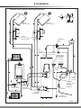
1
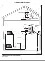
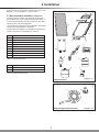
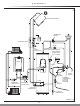
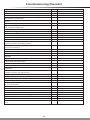
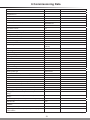
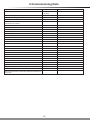
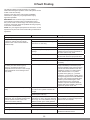
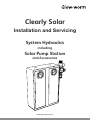
Clearly Solar
Installation and Servicing
System Hydraulics
including
Solar Pump Station
and Accessories
www.glow-worm.co.uk
1
Guarantee Registration
Thank you for installing a new Glow-worm solar system.
Glow-worm products are manufactured to the very highest standard so we are pleased to offer our
customers a Comprehensive Guarantee.
This product is guaranteed for 24 months from the date of installation or 30 months from the date
of manufacture, whichever is the shorter, for parts and labour.
The second year of the guarantee, from the beginning of the 13th month onwards after installation
or manufacture, is conditional upon the product having been serviced by a competent person
(i.e. clear skies registered engineer), in accordance with the manufacturer’s recommendations.
We strongly recommend regular servicing of your product, but where the condition is not met, any
chargeable spare parts or components issued within the applicable guarantee period still benefit
from a 12 month warranty from the date of issue by the manufacturer.
The “Benchmark” Installation, Commissioning and Service Record must be completed on
installation and kept up to date.
We recommend you complete and return as soon as possible your guarantee registration card.
If your guarantee registration card is missing you can obtain a copy or record your registration by
telephoning the Glow-worm Customer Service number 01773 596510.
Customer Service:
01773 596510
Technical Helpline:
01773 828300
General and Sales enquiries:
Tel. 01773 824639
Fax: 01773 820569
To register your Glow-worm product call:
0800 0732142
Benchmark places responsibilities on both manufacturers and installers. The purpose is to ensure that customers are provided
with the correct equipment for their needs, that it is installed, commissioned and serviced in accordance with the manufacturer’s
instructions by competent persons and that it meets the requirements of the appropriate Building Regulations. The Benchmark
Checklist can be used to demonstrate compliance with Building Regulations and should be provided to the customer for future
reference.
Installers are required to carry out installation, commissioning and servicing work in accordance with the Benchmark Code of
Practice which is available from the Heating and Hotwater Industry Council who manage and promote the Scheme.
Visit www.centralheating.co.uk for more information.
2
These instructions consist of, Installation, Servicing, Fault Finding. The instructions
are an integral part of the product and must be handed to the user on completion of the
installation.
CONTENTS
DESCRIPTION
SECTION PAGE
INTRODUCTION
Warnings
Important Information
Statutory Requirements
Notes on the Documentation
Safety Instructions
INSTALLATION
System Specifications
Product Specifications
Component Specifications
Installation
Commissioning
Commissioning Checklist
Commissioning Data
1
2
3
4
5
6
6
7
8
9
11
16
18
19
MAINTENANCE
Inspection and Maintenance
Fault Finding
Solar Fluid Safety Data
7
8
9
21
22
25
3
4
4
5
6
6
WARNINGS
SAFETY
The system must be installed by a competent person, who is responsible for adhering to
the existing standards and regulations.
ALTERATIONS
Under no circumstances should you ever attempt to make alterations to these
components or any other part of the system
SEALED COMPONENTS
Under no circumstances must the user interfere with or adjust sealed parts.
Important Information
Installation and Use Regulations
CE Mark
In your own interests and that of safety, it is the LAW that this
product is installed by a competent person in accordance
with the current issue of these regulations.
The CE mark on this product indicates that it complies with
the basic requirements of the applicable directives as stated
on the data badge.
Local authority planning permission may be required for the
installation. The local authority should be notified.
“Benchmark scheme”
Glow-worm support the Benchmark initiative. It is very
important that the service record is completed by the
installation engineer and handed over to the user.
Control of Substances Hazardous to Health
Under Section 6 of The Health and Safety at Work Act
1974, we are required to provide information on substances
hazardous to health.
The adhesives and sealants used in this product are cured
and give no known hazard in this state.
Solar fluid safety data, see section 9.
Manual Handling
With regards to the “Manual Handling Operations, 1992
Regulations”, the appliance exceeds the recommended
weight for a one man lift, refer to section 9 for more
information.
Electrical Supply
The product MUST be earthed.
All system components shall be of an approved type and all
wiring to current I.E.E. wiring regulations.
External wiring must be correctly earthed, polarised and in
accordance with the relevant standards.
In GB, this is BS 7671.
In IE, this is the current edition of ETCI rules.
The product MUST be connected to a permanent 230V ac,
50Hz supply.
Testing and Certification
This product is tested and certificated for safety and
performance. It is, therefore, important that no alteration is
made to the product, without permission, in writing, by Glowworm.
Any alteration not approved by Glow-worm, could invalidate
the certification, warranty and may also infringe the current
issue of the statutory requirements.
4
Statutory Requirements
IMPORTANT
Collectors and collector assembly
Where no British Standards exists, materials and equipment
should be fit for their purpose and of suitable quality and
workmanship.
ENV 1991-2-4 Eurocode 1 – Basis of design and actions on
structures - Part 2–4: Actions on structures - Wind actions
Solar cylinder and cylinder installation
The installation of this product must be carried out by a
competent person in accordance the rules in force in the
countries of destination.
Pressure equipment directive 97/23/EC Directive of the
European Parliament and Council from 29th May, 1997 for
the approximation of the laws on pressure equipment of the
Member States
Manufacturer’s instructions must not be taken as overriding
statutory requirements.
EN 12977-3 Thermal solar systems and components; Custom
built systems, Part 3: Performance characterisation of stores
for solar heating systems
Statutory Requirements
In GB, the installation of the product must be carried out by a
competent person as described in the following regulations:
EN 12897 Water supply - specification for indirectly heated
unvented (closed) storage water heaters
The manufacturer’s instructions supplied.
EN 806-1 Specifications for installations inside buildings
conveying water for human consumption - Part 1: General
The appropriate Buildings Regulations either The Building
Regulations, The Building Regulations (Scotland),The
Building Regulations (Northern Ireland).
EN 1717 Protection against pollution of potable water
installations and general requirements of devices to prevent
pollution by backflow
The Water Fittings Regulations or Water byelaws in Scotland.
The Health and Safety at Work Act, Control of Substances
Hazardous to Health (COSHH).
EN 60335-2-21 Safety of household and similar electrical
appliances; Part 2: Particular requirements for storage water
heaters (hot water cylinders and hot water boilers) (IEC 3352-21: 1989 and supplements 1; 1990 and 2; 1990, modified).
The Current I.E.E. Wiring Regulations.
Where no specific instructions are given, reference should be
made to the relevant British Standard Code of Practice.
Lightning protection
In IE, the installation must be carried out by a competent
person and installed in accordance with the current edition
of I.S.813 “Domestic Gas Installations”, the current Building
Regulations and reference should be made to the current
ETCI rules for Electrical Installation.
ENV 61024-1 Protection of structures against lightning – Part
1: General principles (IEC 1024-1: 1990; modified) BS 6651
Code of practice for protection of structures against lightning.
GB: the following Codes of Practice apply:
Regulations in Great Britain
BS4814, BS6798, BS5440 Part 1 and 2, BS5546 Part 1,
BS5449, BS6891, BS6700, BS7074 Part 1 and 2, BS7593,
BS7671.
Building Regulation, dating from 1991 (England and Wales)
Requirement G3, L1 and Regulation 7
IE: I.S.813, BS5546, BS 5449, BS 7074, BS 7593.
BS 7671 Requirements for electrical installations (IEE Wiring
Regulations, 16th edition)
Solar system in general
BS 6759-1 Directive for the usage of the safety assembly for
hot water cylinders.
EN ISO 9488 Thermal solar system and components,
terminology (ISO/DIS 9488; 1995)
EN 12975-1 Thermal solar systems and components;
Collectors, Part 1: General requirements
EN 12975-2 Thermal solar systems and components;
Collectors; Part 2: Test methods
ENV 1991-2-3 Eurocode 1 – Basis of design and actions on
structures, Part 2–3: Actions on structures - Snow loads
EN 12976-1 Thermal solar systems and components; Factory
made systems - Part 1: General requirements
EN 12976-2 Thermal solar systems and components; Factory
made systems - Part 2: Testing methods
ENV 12977-1 Thermal solar systems and components;
Custom built systems, Part 1: General requirements
ENV 12977-2 Thermal solar systems and components;
Factory made systems, Part 2: Testing methods
ISO 9459-1: 1993 Solar heating – Domestic water heating
systems – Part 1: Performance rating procedure using indoor
test methods
ISO/TR 10217 Solar energy – Water heating systems – Guide
to material selection with regard to internal corrosion
5
Notes on the Documentation
Notes on the documentation
Other applicable documents
Your solar system is a quality product from Glow-worm.
Collector installation instructions.
This manual covers the solar system, excluding the
cylinder and provides you with information on installation,
commissioning, maintenance and fault finding. It is
supplemented by the installation instructions of the individual
components.
System hydraulic installation instructions.
Observe the manuals for each individual system component
in conjunction with this manual.
Installation instructions for all sub components and
accessories used.
Warranty card.
System electrical installation instructions including Fluropro.
System user instructions including Fluropro.
Installation and user instructions for the boiler.
Look after this manual and pass it on to the user for safe
keeping.
Please observe the safety instructions in this manual when
installing this solar system.
Glow-worm accepts no liability for any damage caused by
failure to observe this manual.
Safety Instructions
Safety instructions
IMPORTANT: A thermostatic mixing valve must be fitted to
the outlet of the cylinder and can be adjusted to the desired
domestic hot water temperature by an installation or service
engineer. Otherwise there is a risk of scalding as the cylinder
outlet temperature at the taps could be up to 85°C.
The entire solar system must always be installed and
operated in accordance with recognised technical standards.
IMPORTANT: Risk of falling! Make sure you adhere to the
valid work protection regulations, in particular when working
on the roof. Make absolutely sure you wear anti-fall devices
whenever there is a risk of falling. (We recommend Glowworm fall protection systems, item no. 0020054985.) Observe
the accident prevention regulations of the trade associations.
IMPORTANT: Risk of being burned or scalded by escaping
hot steam! Steam can escape from unblocked automatic
bleeders if the system is shut down. Therefore block all
automatic bleeders after bleeding.
We recommend using the automatic air separator system
supplied as part of Glow-worm optional pipework kit. It works
fully automatically and does not need to be subsequently
blocked. It must be installed in an area however, in which no
steam can enter, preferably in the return pipe nearby the solar
cylinder.
IMPORTANT: Risk of being burned or scalded by hot
components! Install and replace collectors or collector parts
on very cloudy days. Perform installation work on sunny days
only in the morning or evening or with the collector covered.
IMPORTANT: Risk of being burned or scalded by hot solar
fluid or components! Fill and flush the solar
system when the collectors are cold. Cover the
collectors while doing so.
IMPORTANT: Risk of being burned or scalded by escaping
hot steam! Steam can escape from the expansion relief valve
of the solar pump unit if the system is shut down. To avoid
injuries, you must connect the expansion relief valve to a
collecting container with a hose line.
6
1 System Specifications
1.1 Intended use
The solar system is used for the solar-supported supply of
DHW.
Any other use is considered to be improper. The manufacturer
/ supplier is not liable for any resulting damage. The user
alone bears the risk.
Intended use includes the observance of the system
description and all other applicable documents, as well as
adherence to the maintenance and inspection conditions.
IMPORTANT: We accept no liability for any damage or injuries
caused by failure to observe this manual.
At the end of this manual is a commissioning protocol, which
should be filled in by the installer and/or commissioning
engineer and handed over to the user.
1.2 Design and function of the solar system
The solar system consists of four main components:
The collectors, which absorb the solar radiation and utilise it.
The solar control, which monitors, displays and controls all
functions of the system.
The solar pump unit, which transports the solar heat.
The solar cylinder.
The solar collector transforms solar energy into heat and
transfers the heat energy to a frost-protected solar fluid.
The solar pump of the solar pump unit ensures the heat is
transported from the collector to the twin coil solar cylinder via
a pipe system. The solar pump unit is controlled by the solar
control.
The solar control switches the solar pump on or off as soon
as the difference in temperature between the collector and
solar cylinder falls below or exceeds the preset value. If the
solar energy is insufficient, the control system switches on the
boiler so that the upper third of the cylinder is reheated to the
set value for the domestic hot water temperature. In addition
the solar cylinder can be reheated by the immersion heater
installed by the manufacturer.
The solar expansion vessel compensates pressure
fluctuations in the solar circuit.
On days on which the solar radiation is insufficient to heat the
DHW in the cylinder, the stored water must be reheated by a
heating system. This can be done with boilers or electrically
with an immersion heater.
The optional protection vessel protects the expansion
vessel from increased temperatures in the solar circuit. We
recommend installing a protection vessel.
Local authority planning permission may be required for
the installation. The local authority should be notified
about the intended installation.
The solar system is a closed system and must be bled
carefully. We recommend the automatic air separator
system for this purpose (item no. 0020054969). It works fully
automatically and does not need to be subsequently blocked.
The automatic air separator system must be installed in an
area in which no steam can enter, preferably in the return pipe
between the solar pump unit and the solar cylinder.
7
14162
2 Product Specifications
Clearly Solar
Collector
Solar Pump Unit
Flow
DHW
2 Port Valve
M
Protection
Vessel
Solar Expansion Vessel
Return
Flurocyl
Immersion
Heater
Drinking Water
Expansion Vessel
Automatic Air
Separator System
Boiler
Flow
Return
M
2 Port Valve
Diagram 2.1
2.1 Diagramatic view of the system installation
Refer to diagram 2.1
8
3 Component Specifications
250
2
120
6
Ø 22
Solar Pump Station part no. 0020054961
14829
7
5
Ø 22
3
358
1
Ø 22
Ø 22
Ø 22
Ø 22
4
SOLAR
EXPANSION
VESSEL
CONTAINER
Item
Qty.
Description
1
1
Flow tube with isolating valve with integrated
gravity brake and temperature display
2
1
Return tube with isolating valve with
integrated gravity brake and temperature
display, flow rate meter with fill/vent valve,
circulating pump
3
1
Safety valve with pressure gauge, fill valve
and corrugated tube DN16 including wall
bracket for solar expansion vessel
4
1
Wall bracket for expansion vessel with fitting
5
1
Wall bracket for solar pump station
6
4
22mm Compression nuts
4
22mm Brass olives
4
22-18mm Reducers (discard)
2
C-clips
7
Solar Expansion Vessel
Diagram 3.1
3.1 Solar pump station
Refer to diagram 3.1 for contents and description.
The solar pump unit is equipped with a three-speed solar
pump for the optimum adaptation of the required circulating
volume and the pump capacity in the solar circuit.
Select the pump capacity, depending on the solar system (e.g.
collector surface, pipe diameter, length of the solar circuit), so
that the actual flow rate is slightly higher than the nominal flow
rate. The flow rate meter is used for fine adjustment of the
flow rate.
The solar pump unit is delivered with a water control pack,
consisting of an expansion relief valve and a pressure gauge.
The flow rate meter installed in the return pipe is an essential
component of the solar system. To achieve optimum heat
transfer, you must achieve a certain flow rate, refer to section
5.2.
Upper deviations are not as serious as lower deviations.
Make the rough adjustments with the solar pump first. You can
make the fine adjustments with the adjustment valve of the
flow rate meter. You can view the set value on the display of
the flow rate meter.
The flow rate meter has a fill/vent valve for filling and draining
the solar circuit.
NOTE: Do not under any circumstances set the flow rate
below the calculated flow rate. The collector efficiency will be
considerably reduced.
If you would like to use the solar flexible pipework (DN16
0020054964) from the pump station to the cylinder, please
order an additional two fittings packs, part No. 0020054965,
these contain the relevant fittings for this application.
9
18 litre
Supplied with 1 collector pack
25 litre
Supplied with 2 collector packs
35 litre
Supplied with 3 collector packs
3 Component Specifications
3.2 Solar expansion vessel
3.3 Thermal cut out of the solar pump
The solar expansion vessel, is used to equalise the pressure
while the pressure relief valve blows off the solar fluid into
the collecting container via the pressure release pipe if the
operating pressure of 6 bar is exceeded.
The solar pump must be protected by its own thermal cut out
(TCO) which must be mounted on the solar cylinder (preassembled at the factory on the Glow-worm Flurocyl cylinder).
The power supply to the pump MUST be interrupted at
cylinder temperatures higher than 90°C.
The size of the solar expansion vessel is based on the
expansion volume of the solar system.
3.4 Solar fluid
The expansion vessel not only accommodates the expansion
volume of the solar fluid, but also the entire volume of the
collectors in the event of a shutdown. The total volume of
the solar system is the total of the individual values of the
collector, heat exchanger volume and the volume of the
pipeline.
This information applies to Glow-worm solar fluid (20 l
canister: item no. 0020054968).
Glow-worm solar fluid is a ready-mixed antifreeze and
anticorrosive, consisting of approximately 45% propylene
glycol with anti-corrosion inhibitors and 55% water. It is
resistant to high temperatures.
The admission pressure of the solar expansion vessel can be
set between 0.5 and 4.0 bar.
Component
Volume (l)
Flurocyl 200 l heat exchanger solar circuit
3.04
Flurocyl 250 l heat exchanger solar circuit
3.04
Flurocyl 300 l heat exchanger solar circuit
4.14
Flurocyl 200 l heat exchanger reheating circuit
3.7
Flurocyl 250 l heat exchanger reheating circuit
3.7
Flurocyl 300 l heat exchanger reheating circuit
3.7
Solar pump unit
0.9
Vertical solar thermal flat plate collector
1.85
Horizontal solar thermal flat plate collector
2.16
Protection vessel
5.0
Furthermore the solar fluid has a high thermal capacity.
The inhibitors provide reliable corrosion prevention when
using different types of metal (mixed installations).
NOTE: Do not use any other anti-freeze or inhibitors with the
collector. Only Glow-worm solar fluid is approved.
IMPORTANT: Risk of damage! Glow-worm solar fluid is ready
mixed. You may not under any circumstances mix it with water
or other fluids. Otherwise it will become ineffective as an
antifreeze or anticorrosive, resulting in damage to collectors or
other parts of the system.
Glow-worm solar fluid is infinitely durable in hermetically
sealed containers.
Skin contact is normally not dangerous. Eye contact only
causes minor irritations, you should nevertheless immediately
wash your eyes.
Observe the safety data sheet, see section 9.
Table 3.2 Volume of individual circuits
3.5 Protection of the solar circuit against frost
and corrosion
To protect the solar system reliably against frost in winter, the
entire solar circuit must be filled 100% with solar fluid.
NOTE: You can achieve frost resistance of about -28°C by
filling the solar system with Glow-worm solar fluid. No damage
is caused by frost even at outside temperatures below -28°C,
since the expansive effect of the water is reduced. Check the
antifreeze effect after filling the system and then once a year.
To check the solar fluid; refer to the operating manual of the
solar fluid tester (item no. 0020054984).
10
4 Installation
14172
Make sure that you have all the components required, see
diagram 4.1, 4.2 and tables 4.1 and 4.2, below.
4.1 Recommended installation sequence
Assuming that the cylinder and collectors are fitted with
the exception of the solar system hydraulics and wiring, it
is recommended that the solar pump station is now fitted
followed by the solar circuit pipework.
1
The cylinder and collectors must be installed in accordance
with the separate installation instructions.
Proceed with the installation as described in the following
sections and shown in the diagrams 4.3 and 4.4 .
Item
Description
1
Solar collector panel
2
On-roof, In-roof or Flat roof kit
3
Solar pump unit
4
Fluropro solar control
5
Roof bracket set, concrete tiles
6
Solar fluid (20 litre)
7
Automatic air separator
8
Expansion vessel
9
Protection vessel
2
4
3
5
9
Table 4.1 Typical solar items
Item
Description
1
Single insulated tube DN16 15m x 2
2
Fittings pack for DN16 tube
6
8
7
Table 4.2 Optional pipework kit
Diagram 4.1
14351
Solar set items
1
Optional pipework kit items
11
2
Diagram 4.2
14213
4 Installation
SOLAR COLLECTOR
THERMOSTAT
MIXER
SOLAR COLLECTOR
CIRCUIT PUMP
PUMP
HOT
WATER
CONNECTION
LEGIONNELLA
LOOP (optional)
TEMPERATURE
AND PRESSURE
RELIEF VALVE
(95 °C, 7 BAR)
BOILER
EXPANSION
VESSEL
FLOW
RETURN
MOTORISED
2 PORT VALVE
EXPANSION
RELIEF
VALVE
(6.0 BAR)
PRESSURE
LIMITING VALVE
(3.5 BAR)
WITH LINE
STRAINER
FLOW
MOTORISED
2 PORT VALVE
COLD
WATER
SUPPLY
TUNDISH
RETURN
AUTO AIR
SEPARATOR
FLUROCYL
DRAIN VALVE
Diagram 4.3
12
4 Installation
14212
Collector arrays setup for East / West orientation
N
W
E
S
SOLAR
COLLECTOR
SOLAR
COLLECTOR
SOLAR
COLLECTOR
CIRCUIT PUMP
THERMOSTAT
MIXER
HOT
WATER
CONNECTION
BOILER
PUMP
LEGIONNELLA
LOOP (optional)
TEMPERATURE
AND PRESSURE
RELIEF VALVE
(95 °C, 7 BAR)
EXPANSION
VESSEL
FLOW
RETURN
MOTORISED
2 PORT VALVE
EXPANSION
RELIEF
VALVE
(6.0 BAR)
PRESSURE
LIMITING VALVE
(3.5 BAR)
WITH LINE
STRAINER
FLOW
MOTORISED
2 PORT VALVE
RETURN
COLD
WATER
SUPPLY
TUNDISH
AUTO AIR
SEPARATOR
FLUROCYL
DRAIN VALVE
Diagram 4.4
13
4 Installation
4.2 Fitting the solar pump station
(wall-mounted installation)
IMPORTANT: Use hard solder only, soft solder is NOT
suitable.
Do not use any plastic pipes.
Fit the wall bracket and the pump station flow and return
assemblies.
Flexible stainless steel pipes supplied by Glow-worm or
copper pipes should be used for the solar circuit.
Secure the assemblies in the wall bracket using the two Cclips. Put them onto the flow and return assemblies below the
wall bracket.
Optional Glow-worm flexible pipes for the connection of the
collectors to the solar pump unit.
0020054994: 2 in 1 flexible pipe DN 16 x 15 m
4.3 Pressure relief valve and expansion vessel
0020054964: single flexible pipe DN 16 x 15 m
Fit the pressure relief valve assembly to the connection nozzle
in the pump station return tube assembly.
Two single flexible pipes DN 16 x 15 m are available as part
of the Glow-worm optional pipework kit. Instructions for the
connection of these flexible pipes can be found in separate
installation instructions.
IMPORTANT: Loss of solar fluid! Install a discharge pipe from
the pressure relief valve outlet to a container to ensure that
any hot solar fluid escaping from the system is contained.
Due to the occasionally high temperatures of the solar fluid,
plastic pipes must not be used for the solar circuit. Copper
pipes must be joined using hard soldering or compression
fittings. Soft soldering is NOT suitable.
The solar fluid container is intended as a collecting container
when the system is filled and the container is empty. Connect
a discharge pipe from the relief valve outlet to the intended
location for the container.
Teflon tape can be used on pipework below the Solar Pump
Station.
Mount the expansion vessel wall bracket using screws and
plugs. Screw the flange and the expansion vessel to the wall
bracket.
IMPORTANT: Earth the solar circuit!
The solar pipework must be earthed in accordance with the
requirements of BS 7671 IEE Wiring Regulations. Wiring
protection should be provided if there is high risk of lightning
strikes. The electronics in the solar system, heating system or
in the house could otherwise be destroyed if they were to be
hit by lightning. Connect the collectors to an existing lightning
protection on the house.
The expansion vessel must be mounted vertically and the flow
from the system must enter the vessel from the top. To avoid
accidental spillage or access by children to the fluid, best
practice is to take the discharge pipe right to the bottom of
(but not touching) the container.
The empty solar fluid container is recommended, as reusing it helps to reduce landfill, the contents of the container
are visible (you must be able to see if the safety valve has
discharged) and offers a practical solution. However, if
preferred, an alternative vessel may be used, provided it is
of adequate size, the contents are visible and it is not fully
sealed.
IMPORTANT: Risk of damage to the collectors due to
excessive pressure. The installation of a motorised 2 port
valve in the pipes of the solar system is not allowed, since the
safety devices in the solar circuit could be overridden by it.
The right selection of the pipe diameters plays a significant
role in terms of maximum efficiency of the solar system.
4.4 Notes on the solar circuit pipework
To keep the pressure loss in the solar circuit to a minimum,
the flow velocity in the copper pipe should not be higher than
1.5 m/s.
When installing solar circuit pipework between the collector
array and the cylinder, carefully consider the location of
the pump station and the requirement for an automatic air
separator. The Glow-worm solar system is a closed hydraulic
system in which heat can only be transferred to the cylinder
by means of special heat transfer fluid in the solar system.
Observe the following points to ensure perfect operation with
maximum energy utilisation:
A nominal flow rate of 0.66 l/min per net m2 collector surface is
required by the collectors to achieve optimum heat transfer.
Another decisive criteria for the optimum operation of your
solar system is the speed of the solar pump. The pump must
be able to deliver more than the nominal flow rate at the
specified operating pressure. The selection of the required
pump speed depends on the installed system. Reference
value for the pump selection can be found in section 5.2.
Bleed the system completely during commissioning and
servicing since air in the system has a considerable effect on
the efficiency.
Connections to solar pump station
The pipe diameters should not be too large, otherwise the
the flow in the solar system will slow down, reducing the
efficiency.
IMPORTANT: An air separator is required - refer to diagram
4.5.
Using the compression fittings supplied with the pump station,
connect the pump station ‘flow’ assembly to the collector flow
pipe and the pump station ‘return’ assembly to the collector
return pipe. IMPORTANT: ensure the collector pipes are
connected correctly - the pump station ‘return’ assembly
includes the pump.
Lay all system components in such a way to ensure an even
flow at the required nominal flow rate.
Provide sufficient thermal insulation of the pipes to prevent
excessive heat loss. The insulation must withstand
temperatures up to 150°C. Select weather and UV resistant
insulation which is “bird peck proof“ especially for pipes laid
outside.
Use the fittings included to connect to 22mm copper pipes.
Again using the compression fittings supplied with the pump
station, connect the pump station ‘flow’ assembly to the
cylinder ‘solar circuit flow’ connection then the pump station
‘return’ assembly to the cylinder ‘solar circuit return’.
When using compression fittings, you must consult the
manufacturer of these fittings to check their suitability for solar
systems.
Use compression fittings only if temperatures of up to 200°C
are allowed by the manufacturer.
14
4 Installation
IMPORTANT: Ensure the cylinder pipes are connected
correctly - the pump station return assembly includes the
pump.
The system must be bled whenever it is filled or subjected to
maintenance. Bleeding is performed constantly by means of
the automatic air separator system as long as the solar pump
is in operation.
4.5 Automatic air separator
Fit the protection vessel as shown in diagram 4.6.
Air in the system impairs the efficiency of the solar system
considerably. Install an automatic air separator in the return of
the solar circuit, between the cylinder and solar pump station.
High temperature vapour is unlikely in this area. However,
check with the manufacturer that the device is suitable for
domestic solar system applications.
The protection vessel must be mounted vertically. The flow
from the safety group must enter the vessel at the upper
connection.
A suitable and effective air separator is supplied in all
solar packs or separately (item no. 0020054969). This is
recommended.
14236
14183
The air separator system works fully automatically and does
not need to be isolated.
Flexpipe
Protection Vessel
3/4” Adapter Fitting
Wall Bracket
Solar Expansion
Vessel
Diagram 4.5
Diagram 4.6
15
5 Commissioning
EXAMPLE: The installed (net) collector surface area for
Clearly Solar collectors is 2.35 m2. Multiplied with the value
for the specific flow rate of 0.66 l/m2 • min, it results in a
calculated flow rate, which should be indicated by the flow
rate meter, see diagram 5.1.
You must adhere to the following procedure for the
commissioning of the total system:
Use only Glow-worm solar fluid (item no. 0020054968) for
pressure tests and for flushing and filling the solar circuit.
Select the next pump speed if the calculated flow rate is not
achieved on the flow rate meter. Switch to a lower speed if it
is exceeded. If the flow rate cannot be achieved even at the
highest pump speed, check whether it is possible to use fewer
collectors in series reverting to a combination of series and
parallel connections (eg 2 collectors in series in parallel with
an additional 2 collectors in series).
5.1 Flushing and filling the solar circuit
Glow-worm recommends using the Glow-worm filling pump,
part no. 0020054986, to flush and fill the solar circuit. Observe
the separate user manual when using the Glow-worm filling
pump.
Expansion vessel admission pressure
Use an Allen key to finely adjust the flow rate at the
adjustment valve, see diagram 5.1.
During the commissioning, the gas side admission pressure
pv of the expansion vessel must be adjusted to the equipment
height whilst disconnected. The static pressure pstat
corresponds, to a certain extent, to the static height h between
the collector array and the expansion vessel.
The adjusted flow rate can be viewed on the display, see
diagram 5.1.
Table 5.1 provides reference values for possible pump speeds
depending on the collector connection and pipe length and
cross-section.
10m static height correspond to approx. 1 bar.
pv = pstat = h x 0.1 but not less than 1.5 bar.
The flow rate can be used to calculate and display the
gain. To make an accurate calculation, the flow rate must
be entered into the Fluropro solar control. You can find
further information in the separate system wiring instructions
including the Fluropro solar control.
NOTE: A deviation from the optimum admission or filling
pressure always results in a reduction of the expansion
vessel's effective volume. This can cause operational
malfunctions.
Flushing is performed from the solar pump station to the
cylinder via the collector.
The pump speed is used to achieve a particular flow rate
in the collector array. The final flow rate should not be
significantly above or below the calculated value. Up to 10%
lower solar gain or unnecessarily high power consumption of
the pump could occur.
A self-priming pump with a pressure of 2 to 3 bar is required
to fill the solar circuit.
Collector circuit filling pressure
The filling pressure Pa should be approx. 0.5 bar over the
static pressure Pstat.
Pa = h x 0.1 + 0.5 bar but not less than 2 bar.
14168
1
0,5
3
2
6
5
L/min
1
0,5
3
2
The 3-speed circulating pump can be fine-tuned to adjust the
flow rate to the collector's performance.
4
5.2 Setting the flow rate / pump speed
NOTE: We recommend a value of 0.66 l/min per m2 collector
surface area.
4
Use Table 5.1 to calculate the flow rate to be set by
multiplying the installed collector surface area with the value
of 0.66 l/m2 • min.
5
6
L/min
This is how to do it:
Adjustment
Valve
1,1 l/min
Set the pump speed to roughly set the flow rate as follows:Let the pump run first at the lowest speed (minimum power
consumption).
Check whether the calculated value is achieved on the flow
rate meter.
Clearly Solar, solar collector panel
Flow Rate
Display
Flow rate
Diagram 5.1
Minimum cross-section of the copper pipe in the
solar circuit at a total pipe length of:
Number
in series
l/min
20m
50m
1
1
1.55
15
15
2
2
3.1
15
15
3
3
4.65
15
15
Minimum (speed 1)
Maximum (speed 3)
Pump speed:
Table 5.1 Layout of pipe cross-section and pump speed depending on the collector connection
16
5 Commissioning
5.3 Commissioning checklist
Fill in the commissioning checklist, refer to section 6.
5.4 Benchmark
GB: It is a requirement that the “Benchmark” Installation,
Commissioning and Service Record is completed and left with
the user. This is supplied with the Glow-worm ‘Flurocyl’ range
of cylinders.
IE: it is necessary to complete a “Declaration of Conformity” to
indicate compliance to I.S.813. An example of this is given in
the current edition of I.S.813.
5.5 Hand over to the householder
l Hand over all manuals to the householder.
l Advise the householder to keep the manuals near to the
system.
l Draw special attention to the safety instructions which the
householder must follow.
l Review the user instructions with the householder and
answer any questions.
l Show the householder how to operate the solar control, CH
control and any separate DHW control.
l Inform the householder that the cylinder temperature is
factory set at 65°C and that the DHW temperature can be
adjusted using the TMV by the installer.
l Inform the householder that the immersion heater is
intended as a standby device and should not be used
simultaneously with the boiler to heat the cylinder.
l Inform the householder that they are not permitted to
change the settings made on the solar system.
l Inform the householder that to ensure the continued
efficient and safe operation of the solar system it is
recommended that it is checked and serviced at regular
intervals. The frequency of servicing will depend upon the
installation conditions and usage, but in general, once a year
should be enough.
l
Inform the householder that the boiler and solar cylinder
should be serviced by a qualified engineer annually.
Leave these instructions and the “Benchmark” Installation,
Commissioning and Service record document with the user.
17
6 Commissioning Checklist
1. Assembly
O.K.
Remarks
O.K.
Remarks
O.K.
Remarks
O.K.
Remarks
Roof bracket fixed according to instructions?
Solar pipework connected to potential equalisation?
Roof covering refixed according to instructions after laying the roof bracket?
Roof membrane not damaged?
Pressure release pipe installed at the expansion relief valve of the solar
circuit?
Catch vessel (empty canister) placed under pressure release pipe?
Pressure release pipe installed at expansion relief valve on hot water side
and connected to waste water?
Thermostat mixer installed, temperature set and checked?
2. Commissioning
System filled with prescribed solar fluid?
Solar circuit flushed with solar fluid?
Line strainer cleaned after flushing the system?
System bled several times?
Solar circuit subjected to hydraulic pressure test, including leak inspection
of screw connections and soldering points?
Stuffing boxes at stop valve and fill/vent valve checked for leaks (retighten
union nuts if necessary)?
Temperature and pressure relief valve checked?
Stop valve for reheating source installed (normally motorised 2 port valve)?
Flow rate set according to system manual?
Pump, cylinder heat exchanger and collector bled (gravity brake blocked for
bleeding)?
Gravity brake released?
Fill/vent valve caps screwed tight?
Cylinder bled?
Heating circuit bled?
Does the system installation meet the requirements of the building
regulations?
Has the system been installed and started up in accordance with the
installation manuals of the manufacturer?
3. Control systems
Do the temperature sensors display plausible values?
Solar pump running and circulating (flow rate measuring meter)?
Solar circuit and cylinder become warm?
The temperature difference between the flow and return is a max. of 10 to
14 °C at full sunshine?
Correct hydraulic plan set
4. Instruction
The system user has been instructed as follows:
– Basic functions and operation of the solar control?
– Functions and operation of the reheating system?
– Frost protection of the system?
– Maintenance intervals?
– Manuals/documents (possibly with special circuit plan) handed over to the
user?
Table 6.1 Commissioning checklist
18
6 Commissioning Data
Information
Unit
Value/Detail
Benchmark no.
Registration no.
Basic acceptances
Number of persons
Additional hot water equipment
Washing machine,
dishwasher etc.
Circulation
Available/Not available
Circulation runtime
h/d
(please tick as appropriate)
Daily hot water consumption in
l/d
At a cylinder temperature of
°C
Estimated solar coverage of the total hot water consumption
%
Collector array performance data
Installed effective collector surface area
m2
Maximum power at full solar radiation
kW (500–600 W/m2
collector)
Solar cylinder
Appliance type
Vented/Unvented
Appliance designation
Capacity
l
Serial number
Boiler
Appliance type
Appliance designation
Serial number
Boiler system type
Open/Closed
Installation location of pressure limiting valve
System values
Hot water temperature at the nearest tap
°C
Achievable maximum cylinder temperature
°C
Maximum hot water temperature
°C
Maximum hot water volume at maximum temperature
l/min.
Boiler flow temperature
°C
Operating pressure setting at pressure limiting valve
bar
Charge pressure in DHW expansion vessel (check before
filling)
bar
Charge pressure in solar expansion vessel (check before
filling)
bar
Cold water system pressure at pressure limiting valve (cold)
bar
Set flow rate
l/min
Temperature difference between flow and return at full solar
radiation
Kelvin
Volume of solar expansion vessel
l
Operating pressure at solar pump unit pressure gauge in
cold condition
bar
Table 6.2 Commissioning data
19
6 Commissioning Data
Information
Unit
Frost protection set to
Density of solar fluid >
1.05 g/cm3
Value/Detail
Controller settings
Installed controller(s)/timer(s)
Manufacturer
Reheating with boiler starts at (TSP1 min. see installation
manual of solar control)?
°C
Switch-on temperature difference:
Kelvin
Switch-off temperature difference:
Kelvin
Other settings
Important activated functions
Name of the installer (in block letters)
Corgi ID No.
Date
Signature
Signature of the user to confirm the receipt of all manuals of
the system
Table 6.2 Commissioning data (continued)
20
7 Inspection and Maintenance
The operational reliability of the solar system may be
impaired, resulting in damge to property or personal injury, if
the inspections and maintenance work are not carried out.
The main maintenance work on the solar system and the
corresponding maintenance intervals are specified in table
7.1.
Maintenance
Maintenance interval
Solar circuit
Check the frost protection of the solar fluid (use the Glow-worm 0020054984 solar fluid tester)
Annually
Check the system pressure
Annually
Check the pH value of the solar fluid (with litmus paper, pH > 7.5)
Annually
Check the solar pump function
Annually
Bleed the system
Annually
Check the circulating volume in the solar circuit
Annually
Check the hot water thermostat mixer function
Annually
Refill with solar fluid if necessary
Annually
Check the quantity of blow-off liquid
Annually
Release the return flow preventer
Annually
Check the charge pressure of the expansion vessel
Annually
Collector
Visual inspection of the collector, collector fastenings and connections
Annually
Check whether the brackets and collector components are clean and fitted properly
Annually
Check the pipe insulation for damage
Annually
Solar control
Check the pump function (on/off, automatic)
Annually
Check the sensor temperature display
Annually
Reheating
Check the circulation pump
Annually
Check the timer/time programme settings
Annually
Reheating: does it deliver the desired deactivation temperature?
Annually
Solar cylinder
Bleed the heat exchanger if necessary
Annually
Check the connections for leaks
Annually
Check the temperature and pressure relief valve
Annually
Checking the expansion relief valve
Annually
Table 7.1 Maintenance checklist
21
8 Fault Finding
The following tables provide information on possible
malfunctions during the operation of the solar system as well
as their cause and remedy.
All work on the Glow-worm solar system (installation,
maintenance, repairs etc.) may be performed only by
approved specialists.
IMPORTANT: Risk of serious injury or death! Never try to
correct faults in the solar system yourself. Bear in mind
that you risk death or serious injury if the work is performed
incorrectly. Consult an approved qualified servicing company
in the event of malfunctions.
NOTE: Only use original spare parts from Glow-worm. for the
replacement of parts. We recommend making a maintenance
agreement.
Malfunction
Cause
Remedy
1. No current available.
Check the power cables and fuses.
2.Temperature difference set too high or
controller is not switching.
Check the controller.
Solar pump
Pump is not running although the
collector is warmer than the cylinder
(neither motor noises can be heard nor
vibrations felt).
Check the temperature sensor.
Reduce the temperature difference.
3. Maximum temperature reached.
4. Pump shaft jammed by deposits in the
bearings.
Switch temporarily to max. speed or
unblock the rotor, insert a screwdriver in
the notch and turn it by hand.
5. Pump dirty.
Dismantle the pump and clean it. Close
the flow rate meter and pump ball valve.
6. Pump defective.
Replace the pump.
7. Flow rate set incorrectly
Check the setting and adjust it if
necessary.
Pump is running, but no solar fluid
Air is in the pipework.
is coming from the collector (pump
gets hot). Forward and return flow
temperatures are the same or the storage
tank temperature not increasing at all or
only slowly.
Check the system pressure. Operate the
pump intermittently at maximum power.
Open the bleeder at the pump and at the
cylinder and bleed. Bleed the back flow
prohibition. If there is no improvement,
check whether there is a “u pocket”
anywhere in the piping (e. g. at beam
projections or at the bend of water pipes).
Change the pipework or install additional
air vents. If the system has already been
started up and is refilled again, check
the automatic air vent: Unscrew the
protective cap and check the floater for
mobility with a blunt needle. If the floater
is jammed, replace the air vent.
Pump goes on too late and stops running
early.
1. The temperature difference between
the collector and cylinder has been set
too high.
Reduce the temperature difference.
2. Collector connection pieces not
insulated (tube collector).
Insulate the collector connection pieces.
Pump starts up and goes off shortly
afterwards. This is repeated several times
until the system runs its course. The
same occurs in the evening.
The temperature difference of the
controller is too low or the pump speed is
set too high. The solar radiation is not yet
sufficient to heat up the entire pipework.
Check whether the entire pipework is
fully insulated. Increase the temperature
difference of the controller.
The pump is making noises.
1. Air in the pump
Bleed the pump.
2. Insufficient system pressure.
Increase the system pressure.
Incorrect position of the collector sensor.
Position the collector sensor in the flow.
Insulate the collector sensor.
Table 8.1 Fault Finding
Solar system
Clocking of the system.
22
8 Fault Finding
Malfunction
Cause
Remedy
The pressure gauge indicates a drop in
pressure.
A drop in pressure is normal shortly
after filling the system, since air still
escapes from the system. If a pressure
drop occurs again later on, the cause
may be an air bubble, which has been
subsequently released.Furthermore there
are fluctuations to the pressure in normal
operation mode between 0.2 to 0.3 bar,
depending on the system temperature. If
the pressure drops continuously, there is
a leak in the solar circuit, in particular in
the collector array.
First check all screw connections, stuffing
boxes at gate valves and threaded
connections, then the soldering points.
Check the collector array and replace a
tube or the collector if necessary.
The water pressure and amount of
discharged water decreases at hot water
taps.
Pressure in the main cold water supply
too low.
Inform the user and notify the water
supply company.
Line strainer in the pressure limiting valve
dirty.
Clean the line strainer in the pressure
limiting valve and replace it if necessary.
Pressure limiting valve defective.
Replace the pressure limiting valve.
Blockage in the system.
Unblock the blockage and replace any
blocked parts.
Check the system for water leaks at the
expansion relief valve and temperature /
pressure limiting valve.
The system is making noises. Normal in
the first few days after filling the system.
If it occurs later, there are two possible
causes:
1. The system pressure is too low. The
pump is drawing air via the bleeder.
Increase the system pressure.
2. Pump power set too high.
Switch to a lower speed.
The solar gain is unusually low.
The pipe insulation is too thin or incorrect. Check the insulation. Check the layout
The system may have been designed
of the system (collector size, shading,
incorrectly.
pipe lengths) and modify the system if
necessary.
Solar control
Display example “NTCA Err“ or similar
(reference system wiring instructions
including Fluropro solar controller)
Defective sensor (short circuit or
interruption).
1. Check the cable connection.
2. Measure the resistance values of
the disconnected sensor at known
temperatures, and compare these with
the manufacturer's specifications.
3. Inspect the piping for damage.
1. The gravity brake is blocked.
1. Check the position of the blue handle.
2. Check the gravity brake for tightness
(jammed cuttings, particles of dirt in the
sealing face).
3. Do not connect the solar heat
exchanger directly, rather pull the supply
pipes downwards and then upwards to
the collector (syphon supports the gravity
brake) or install a 2-port valve, which
is switched on at the same time as the
pump.
2. One-pipe circulation in the event of
short pipe networks with low pressure
loss.
Install a gravity brake (as close as
possible to the cylinder).
1. Air in the reheating heat exchanger.
Bleed the reheating heat exchanger.
Solar cylinder
The cylinder cools down at night. The
flow and return temperatures vary after
switching off the pump. The collector
temperature is higher than the air
temperature at night.
Reheating is not working. The boiler
runs for a short time, goes off and then
back on again. This is repeated until the
cylinder is at its target temperature.
2. Heat exchanger surface area too small. Compare the specifications of the boiler
manufacturer with those of the cylinder
manufacturer. The problem may be able
to be solved by a higher setting of the
flow temperature at the boiler.
Table 8.1 Fault Finding (continued)
23
8 Fault Finding
Malfunction
Cause
Remedy
Only cold or lukewarm water comes out
of the taps.
1. Cold and hot water connections on the
cylinder have been mixed up.
Turn off the cold water supply, then
let water flow out via the hot water
connection. Only a few litres of water
flow out if the connection is laid correctly.
The inlet of the hot water draw-off pipe
then rests in the air space; no further
emptying is possible. If the entire solar
cylinder runs empty via the hot water
connection, the connections have been
laid incorrectly. Change the connections!
2. Hot water thermostat mixer set too low.
Increase the setting.
3. Solar heating insufficient; boiler does
not reheat.
External control device faulty.
Check whether the boiler is working.
Air in the reheating heat exchanger
Bleed the reheating heat exchanger.
Cylinder temperature sensor defective.
Check the thermal cut out and reset it.
Replace the cylinder thermostat.
Dirt on the valve seat of the expansion
relief valve.
Check the expansion relief valve and
reset it manually.
Pressure limiting valve defective.
Switch off the boiler and immersion
heater and check whether the pressure
behind the pressure limiting valve is lower
than 3.0 bar if water flows out only when
heating up. If so, replace the pressure
limiting valve.
Expansion vessel defective.
Check the pressure in the expansion
vessel. If the pressure is insufficient,
re-establish the pressure and check
whether the equalisation tank maintains
the pressure.
Expansion relief valve defective.
If the pressure is normal, replace the
expansion relief valve.
Dirt on the valve seat of the temperature
and pressure relief valve.
Check the seat of the temperature
and pressure relief valve and reset it
manually.
Temperature control of the boiler
defective.
Check the temperature control of the
boiler if water only comes out when
reheating with the boiler. Check whether
the two port valve switches to the heating
position after reaching the cylinder
temperature.
Cylinder temperature sensor defective.
Check the cylinder temperature sensor
and the corresponding thermal cut outs
and replace the temperature sensor and
reset the thermal cut outs if necessary.
Two port valve defective.
Check whether the two port valve is
working and replace it if necessary.
Temperature and pressure relief valve
defective.
Replace the temperature and pressure
relief valve if water only comes out when
heating up with the immersion heater.
Immersion heater defective.
Check the temperature sensor of the
immersion heater and the corresponding
thermal cut out and replace the
immersion heater if necessary.
Water flows out of the expansion relief
valve (only when heating up).
Water comes out of the temperature and
pressure relief valve (only when heating
up).
Check whether the external control
device is working.
Check whether the two port valve is in the
hot water position.
Replace the two port valve.
Table 8.1 Fault Finding (continued)
24
9 Solar Fluid Safety Data
10.1 Safety data sheet
6 Measures to be taken if substances are released
accidentally
1 Substance/Formulation and company name
Individual-related measures:
No particular measures required.
Information on the product:
Trade name of the Glow-worm solar fluid (item no.
0020054968)
Environmental measures:
The product may not be discharged into waters without pretreatment (biological sewage plant).
2 Composition/Information on components
Chemical properties
Watery solution of 1.2 propylene glycol with corrosion
inhibitors
Cleaning/Collection methods:
Pump out the product in the event of large quantities. Absorb
small quantities with appropriate fluid bonding material.
Then dispose of them according to regulations. Rinse away
splashes with plenty of water. Inform the local water authority
in the event of large quantities which could flow into the
drainage or waters.
3 Possible risks
No particular risks known
4 First-aid measures
General notes:
Remove dirty clothes.
7 Handling and storage
Handling:
Good ventilation of the workplace, no other particular
measures required.
After inhaling:
Discomfort after inhaling fumes/aerosol: fresh air, help from a
doctor.
Fire and explosion protection:
No exceptional measures required. Cool any endangered
containers with water.
After skin contact:
Wash off with water and soap.
After eye contact:
Wash thoroughly under running water with wide open eyes for
at least 15 minutes.
Storage:
Close containers tightly and store them at dry places. Do not
use any galvanised containers for storage.
After swallowing:
Rinse your mouth and then drink plenty of water.
8 Limitation of exposure and personal protective
equipment
Notes for the doctor:
Treatment of symptoms (decontamination, vital function), no
specific antidote known.
Personal protective gear:
Hand protection: chemical-resistant protective gloves (EN
374). Suitable materials even in the event of prolonged, direct
contact (recommended: protection index 6, corresponding
to > 480 minutes permeation time according to EN 374):
flour elastomer (FKM) – 0.7 mm layer thickness. Suitable
materials for brief contact or splashes (recommended: at least
protection index 2, corresponding to > 30 minutes permeation
time according to EN 374): nitrile rubber (NBR) – 0.4 mm
layer thickness. Due to the large variety of types, observe the
instruction manuals of the manufacturer.
5 Firefighting measures
Appropriate extinguishing agents:
Spray, solid extinguishing agent, alcohol-fast foam, carbon
dioxide (CO2)
Particular hazards:
Fumes which are detrimental to health. Formation of smoke/
mist. The specified substances/substance groups may be
released in the event of a fire.
Eye protection:
Safety glasses with lateral protection (framed glasses) (EN
166)
Special protective equipment for fire fighting:
Wear a breathing apparatus which is independent of the
circulating air in the event of a fire.
General safety and hygiene measures:
Observe the usual protective measures for dealing with
chemicals.
Further details:
The hazard depends on the combustible substances and
the fire conditions. Polluted fire water must be disposed of
according to local official regulations.
9 Physical and chemical properties
Form: fluid
Colour: violet
Odour: product-specific
Solidification temperature: approx. -28 °C (DIN 51583)
Boiling temperature: > 100 °C (ASTM D 1120)
Flash point: none
Lower explosion limit: 2.6 % by vol. (details for
Upper explosion limit: 12.6 % by vol. 1.2 propylene glycol)
Ignition temperature: omitted
vapour pressure (20 °C): 20 mbar
Density (20 °C): approx. 1.030 g/cm3 (DIN 51757)
Water solubility: entirely soluble
Solubility (qualitative) solvent: polar solvents: soluble
pH value (20 °C): 9.0 – 10.5 (ASTM D 1287)
Viscosity, kinematic (20 °C): approx. 5.0 mm2/s (DIN 51562)
25
9 Solar Fluid Safety Data
10 Stability and reactivity
15 Regulations
Substances to be avoided: Strong oxidants
Labelling in accordance with EC directives/national
regulations: No labelling obligation
Dangerous reactions:
No dangerous reactions if the storage and handling
regulations/notes are observed
Other regulations: water hazard class (Germany, Appendix 4
of the VwVwS (administrative regulation on water-pollutant
substances) from 17.05.1999): (1), slightly water-pollutant
Dangerous decomposition products:
No dangerous decomposition products if the storage and
handling regulations/notes are observed.
16 Other information
The safety data sheet is intended to provide essential
physical, safety-related, toxicological and ecological data
and give recommendations for safe handling or safe storage,
handling and safe transport of chemical substances and
formulations.
11 Toxicological information
Acute toxicity:
LD50/oral/rat: > 2000 mg/kg
Primary skin irritation/rabbit: not irritating.
(OECD guideline 404)
Primary irritation to the mucous membrane/rabbit: not
irritating.
(OECD guideline 405)
No liability is assumed for damage in connection with the
usage of this information or the usage, application, adaptation
or processing of the products described here.
This does not apply as long as we, our statutory agents
or assistants are liable in the event of intention or gross
negligence.
Additional notes:
The product has not been checked. The statements have
been taken from the individual components.
No liability is assumed for indirect damage.
12 Ecological information
This information has been compiled to the best of our
knowledge and conscience according to our current state of
knowledge.
Ecological toxicity:
Fish toxicity: LC50 leuciscus idus (96 h): > 100 mg/l
Aquatic invertebrates: EC50 (48 h): > 100 mg/l
Water plants: EC50 (72 h): > 100 mg/l
Micro-organisms/effect on activated sludge:
DEV-L2 > 1000 mg/l. No disturbances to the biodegrading
activity of the activated sludge are expected in adapted
biological sewage plants if discharged appropriately in low
concentrations.
No guarantee can be made for product properties.
Assessment of aquamatic toxicity:
The product has not been checked. The statements have
been taken from the properties of the individual components.
Persistence and biodegradability/information on elimination:
OECD 301 A test method (new version)
Analysis method: DOC acceptance
Degree of elimination > 70 % (28 d)
Assessment: easily biodegradable.
13 Note on disposal
Disposal:
Glow-worm solar fluid (item no. 0020054968) must be
disposed of at an appropriate waste site or waste incineration
plant, for example, while observing local regulations.
Contact the local municipal sanitation office or the mobile
environmental service for quantities under 100 l.
Uncleaned packings:
Uncontaminated packings can be reused. Dispose of
packings which are unable to be cleaned together with the
substance.
14 Transport information:
VbF: not subject to the ordinance on combustible fluids.
Mailing permitted. GGVE/RID: -, UN no.: -, GGVS/ADR: -,
IATA DGR: -, IMDG code: -, TA air: -. No dangerous goods
according to transport regulations.
26
27
Glow-worm, Nottingham Road, Belper, Derbyshire. DE56 1JT
Because of our constant endeavour for improvement, details may vary slightly from those shown in these instructions.
28
0020055003-04 02.09
0020055003